EP4424451A1 - Verfahren zur herstellung eines verbundenen körpers - Google Patents
Verfahren zur herstellung eines verbundenen körpers Download PDFInfo
- Publication number
- EP4424451A1 EP4424451A1 EP22889715.3A EP22889715A EP4424451A1 EP 4424451 A1 EP4424451 A1 EP 4424451A1 EP 22889715 A EP22889715 A EP 22889715A EP 4424451 A1 EP4424451 A1 EP 4424451A1
- Authority
- EP
- European Patent Office
- Prior art keywords
- rotary tool
- rotational speed
- metal member
- stirring pin
- joining process
- Prior art date
- Legal status (The legal status is an assumption and is not a legal conclusion. Google has not performed a legal analysis and makes no representation as to the accuracy of the status listed.)
- Pending
Links
Images


Classifications
-
- B—PERFORMING OPERATIONS; TRANSPORTING
- B23—MACHINE TOOLS; METAL-WORKING NOT OTHERWISE PROVIDED FOR
- B23K—SOLDERING OR UNSOLDERING; WELDING; CLADDING OR PLATING BY SOLDERING OR WELDING; CUTTING BY APPLYING HEAT LOCALLY, e.g. FLAME CUTTING; WORKING BY LASER BEAM
- B23K20/00—Non-electric welding by applying impact or other pressure, with or without the application of heat, e.g. cladding or plating
- B23K20/12—Non-electric welding by applying impact or other pressure, with or without the application of heat, e.g. cladding or plating the heat being generated by friction; Friction welding
- B23K20/122—Non-electric welding by applying impact or other pressure, with or without the application of heat, e.g. cladding or plating the heat being generated by friction; Friction welding using a non-consumable tool, e.g. friction stir welding
- B23K20/123—Controlling or monitoring the welding process
- B23K20/124—Controlling or monitoring the welding process at the beginning or at the end of a weld
-
- B—PERFORMING OPERATIONS; TRANSPORTING
- B23—MACHINE TOOLS; METAL-WORKING NOT OTHERWISE PROVIDED FOR
- B23K—SOLDERING OR UNSOLDERING; WELDING; CLADDING OR PLATING BY SOLDERING OR WELDING; CUTTING BY APPLYING HEAT LOCALLY, e.g. FLAME CUTTING; WORKING BY LASER BEAM
- B23K20/00—Non-electric welding by applying impact or other pressure, with or without the application of heat, e.g. cladding or plating
- B23K20/12—Non-electric welding by applying impact or other pressure, with or without the application of heat, e.g. cladding or plating the heat being generated by friction; Friction welding
- B23K20/122—Non-electric welding by applying impact or other pressure, with or without the application of heat, e.g. cladding or plating the heat being generated by friction; Friction welding using a non-consumable tool, e.g. friction stir welding
-
- B—PERFORMING OPERATIONS; TRANSPORTING
- B23—MACHINE TOOLS; METAL-WORKING NOT OTHERWISE PROVIDED FOR
- B23K—SOLDERING OR UNSOLDERING; WELDING; CLADDING OR PLATING BY SOLDERING OR WELDING; CUTTING BY APPLYING HEAT LOCALLY, e.g. FLAME CUTTING; WORKING BY LASER BEAM
- B23K2103/00—Materials to be soldered, welded or cut
- B23K2103/08—Non-ferrous metals or alloys
- B23K2103/10—Aluminium or alloys thereof
Definitions
- the present invention relates to a method for manufacturing a joined body.
- Patent Literatures 1-3 disclose methods for manufacturing a joined body (liquid-cooling jacket) by friction stir welding.
- the jacket body is made of an aluminum alloy casting material such as ADC12
- the sealing body is made of an aluminum alloy expansible material such as A1050, so that the jacket body has a higher hardness than the sealing body.
- Patent Literatures 1-3 the sealing body is placed on the jacket body, and friction stir welding is performed to the butted portion between the jacket body and the sealing body. After welding the butted portion, in a leaving section, the stirring pin of the rotary tool F is moved toward an ending position that is set on the sealing body while gradually increasing the rotational speed, and the rotary tool is made to leave (removed from) the sealing body.
- the present invention seeks to provide a method for manufacturing a joined body that can achieve a good surface finish of the joined body and prevent damage to the rotating tool.
- the present invention provides a method for manufacturing a joined body, in which a first metal member and a second metal member are joined together by friction stirring, wherein the first metal member is made of a first aluminum alloy, and the second metal member is made of a second aluminum alloy, the first aluminum alloy having a higher hardness than the second aluminum alloy, and wherein a rotary tool used in the friction stirring has a stirring pin, the method comprising the steps of: a butting process to form a butted portion by butting a side face of the first metal member and a side face of the second metal member, and a primary joining process to perform friction stirring to the butted portion by moving the stirring pin of the rotary tool at a predetermined depth along a set moving track that is set on an inner side relative to the side face of the second metal member in a state that the stirring pin of the rotary tool being rotated is inserted into the second metal member and that an outer circumferential face of the stirring pin is slightly in contact with the first metal member, wherein in the primary joining process
- a final rotational speed in the leaving section is set to 10% or higher and 50% or lower.
- the rotational speed for performing friction stir welding at the butted portion is 5,000 rpm or higher and 20,000 rpm and lower, and that a final rotational speed in the leaving section is 1,000 rpm or higher and 8,000 rpm or lower.
- the method for manufacturing a joined body further includes a preparation process to form the first metal member by die-casting.
- a starting position is set on the set moving track, and an insertion section is provided, in which before friction stir welding is performed to the butted portion, the stirring pin is inserted into the starting position and the rotary tool is lowered while being moved from the starting position, and that in the primary joining process, friction stir welding is performed by moving the rotary tool such that before the rotary tool is made to leave the first metal member at the ending position, the stirring pin passes through the starting position.
- a starting position is set on the set moving track, and an insertion section is provided, in which before friction stir welding is performed to the butted portion, the stirring pin is inserted into the starting position and the rotary tool is lowered while being moved from the starting position, and that in the insertion section, the rotary tool is moved toward a middle point that is set on the set moving track and lowered, while gradually decreasing the rotational speed from a rotational speed higher than the predetermined rotational speed.
- a starting position is set on the second metal member at an inner side relative to the set moving track, and an insertion section is provided, in which before friction stir welding is performed to the butted portion, the stirring pin is inserted into the starting position and the rotary tool is lowered while being moved from the starting position, and that in the insertion section, the rotary tool is moved and lowered, while gradually decreasing the rotational speed from a rotational speed higher than the predetermined rotational speed.
- a starting position is set on the first metal member at an outer side relative to the set moving track, and an insertion section is provided, in which before friction stir welding is performed to the butted portion, the stirring pin is inserted into the starting position and the rotary tool is lowered while being moved from the starting position, and that in the insertion section, the rotary tool is moved and lowered, while gradually increasing the rotational speed from a rotational speed lower than the predetermined rotational speed.
- a good surface finish of the joined body can be provided and damage to the rotary tool can be prevented.
- a joined body (liquid-cooling jacket) 1 is composed of a jacket body (first metal member) 2 and a sealing body (second metal member) 3.
- the joined body 1 is a device to cool a heating element placed thereon by flowing a fluid through the joined body 1.
- the jacket body 2 and the sealing body 3 are integrated together by friction stir welding.
- a "front face” means the face opposite to a "back face”.
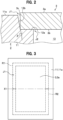
- the jacket body (first metal member) 2 is mainly composed of a bottom portion 10 and a peripheral wall portion 11.
- the material of the jacket body 2 is not particularly limited so long as it is a metal capable of being frictionally stirred, and in this embodiment, the jacket body 2 is made of mainly a first aluminum alloy.
- the first aluminum alloy is, for example, an aluminum alloy casting material such as JISH5302 ADC12 (based on Al-Si-Cu).
- the bottom portion 10 is a plate-like member having a rectangular shape.
- the peripheral wall portion 11 is a wall portion standing on the peripheral edge portion of the bottom portion 10 and having a rectangular frame shape.
- a recessed portion 13 is defined by the bottom portion 10 and the peripheral wall portion 11.
- a peripheral wall step portion 12 is formed at an inner peripheral edge of the peripheral wall portion 11.
- the peripheral wall step portion 12 is composed of a step bottom face 12a and a step side face (side face) 12b obliquely standing up from the step bottom face 12a. As shown in FIG.
- an inclination angle ⁇ of the step side face 12b may be appropriately set, and in this embodiment, the inclination angle ⁇ is the same as or approximately the same as an inclination angle ⁇ of a stirring pin F2 of a rotary tool F shown in FIG. 7 .
- the step side face 12b may stand up orthogonally to the step bottom face 12a.
- the jacket body 2 of this embodiment is integrally formed, but may be integrated by joining plural elements making up the peripheral wall portion 11 with a sealing agent or the like.
- the sealing body (second metal member) 3 is a plate-like member to seal an opening portion of the jacket body 2.
- the sealing body 3 is not particularly limited so long as it is made of a metal capable of being frictionally stirred. In this embodiment, it is made of mainly a second aluminum alloy.
- the second aluminum alloy has a lower hardness than the first aluminum alloy.
- the second aluminum alloy is, for example, an aluminum alloy expansible material such as JIS A1050, A1070, A1100, A6063.
- a method for manufacturing the joined body according to this embodiment will be described.
- a preparation process, a butting process and a primary joining process are performed.
- the preparation process is a process to prepare the jacket body 2 and the sealing body 3.
- a method for manufacturing the jacket body 2 and the sealing body 3 is not particularly limited.
- the jacket body 2 is formed by die-casting, and the sealing body 3 is formed by extrusion.
- the butting process is a process to place the sealing body 3 on the jacket body 2 and to but side faces of the sealing body 3 and the jacket body 2 against each other as shown in FIG. 2 .
- the side face 3c of the sealing body 3 is butted against the step side face (side face) 12b of the peripheral wall step portion 12 by the butting process to form a first butted portion J1. Since the step side face 12b is inclined toward the outside, a V-shaped cross sectional gap is formed at the first butted portion J1.
- the first butted portion J1 has a rectangular shape along the periphery of the sealing body 3 in a plan view.
- a back face 3b of the sealing body 3 is butted against the step bottom face 12a of the peripheral wall step portion 12 to form a second butted portion J2.
- the thickness of the sealing body 3 may be appropriately set, and in this embodiment, it is larger than the height dimension of the step side face 12b.
- one side region (in FIG. 3 , upper side region) with respect to a middle line X1 set on the sealing body 3 is referred as a first region R1.
- the other side region (in FIG. 3 , lower side region) with respect to the middle line X1 is referred to as a second region R2.
- the middle line X1 is a line passing through the middle position of the sealing body 3 in a longitudinal direction.
- a "set moving track L1" (dash-dotted line) is set on an inner side relative to the first butted portion J1.
- the set moving track L1 is a moving track of the rotary tool F necessary for joining the first butted portion J1 in a primary joining process to be described later. Since the stirring pin F2 of the rotary tool F is slightly brought in contact with the step side face 12b in this embodiment as described later, the set moving track L1 is set to be a rectangular shape in a plan view on the inner side relative to the side face 3c.
- the primary joining process is a process to perform friction stir welding to the first butted portion J1 using the rotary tool F.
- the first primary joining process in which the first region R1 (see FIG. 3 ) of the first butted portion J1 is joined, and the second primary joining process in which the second region R2 (see FIG. 3 ) of the first butted portion J1 is joined are respectively performed.
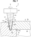
- the rotary tool F is composed of a connecting portion F1 and the stirring pin F2.
- the rotary tool F is made of, for example, tool steel.
- the connecting portion F1 is a portion to be connected to a rotary shaft of a friction stir device (not shown).
- the connecting portion F1 has a circular columnar shape, and has a thread hole (not shown) into which a bolt is fastened.
- the stirring pin F2 hangs down from and is coaxial with the connecting portion F1.
- the stirring pin F2 has a smaller diameter with increasing distance from the connecting portion F1.
- the stirring pin F2 has a flat face F3 at the tip thereof.
- the stirring pin F2 has a spiral groove formed on the outer circumferential face thereof.
- the spiral groove is formed to rotate counterclockwise with increasing distance from the base end toward the tip.
- the spiral groove is formed to rotate counterclockwise with increasing distance from the base end toward the tip when it is viewed from the upper side.
- the spiral groove is formed to rotate clockwise with increasing distance from the base end toward the tip.
- the spiral groove of this case is formed to rotate clockwise with increasing distance from the base end toward the tip when it is viewed from the upper side.
- three sections - comprising an insertion section, an original section and a leaving section - are frictionally stirred continuously.
- the insertion section extends from a starting position SP1 to a middle point S1.
- the original section extends from the middle point S1 to the other middle point S2, both located on the set moving track L1.
- the leaving section extends from the other middle point S2 to an ending position EP1.
- the middle points S1 and S2 are set at positions at which the middle line X1 and the set moving track L1 intersect.
- the starting position SP1 is set on an inner side relative to the set moving track L1 on a front face 3a of the sealing body 3.
- the starting position SP1 is set at a position where an angle ⁇ 1 defined by a line segment connecting the starting position SP1 and the middle point S1 and the set moving track L1 is an obtuse angle.
- the angle ⁇ 1 is not particularly limited so long as it is an obtuse angle. However, it is preferable that the angle ⁇ 1 is 120° or greater, more preferably 150° or greater, and even more preferably 170° or greater, and less than 180°, and more preferably 175° or less. If the angle ⁇ 1 is equal to or greater than the above-described lower limit value, an insertion hole provided at the starting position SP1 on the front face of the sealing body 3 is formed closer to the outer periphery of the sealing body 3.
- the rotational speed of the rotary tool F for friction stir welding may be set as desired.
- the rotational speed of the rotary tool F may be gradually lowered from a rotational speed higher than that of the rotary tool F in the original section.
- the stirring pin F2 After the stirring pin F2 reaches the middle point S1, the stirring pin F2 continuously shifts to the original section for friction stir welding. As shown in FIGS. 5 and 7 , in the original section, the rotary tool F is moved such that the axis C of the stirring pin F2 is overlapped with the set moving track L1. According to this embodiment, as shown in FIG. 7 , the peripheral wall portion 11 of the jacket body 2 and the front face 3a of the sealing body 3 are separated from the connecting portion F1 of the rotary tool F, and only the stirring pin F2 is inserted into the jacket body 2 and the sealing body 3.
- the "predetermined depth” for the stirring pin F2 is set to such an extent that the flat face F3 of the stirring pin F2 is slightly in contact with the step bottom face 12a.
- the "predetermined depth” for the stirring pin F2 may be appropriately set.
- the "predetermined depth” for the stirring pin F2 may be set to a depth not to reach the step bottom face 12a.
- a contact dimension of the flat face F3 of the stirring pin F2 against the step bottom face 12a is referred to as an insertion amount D (not shown in the drawings).
- the insertion amount D is set in a range 0 ⁇ D ⁇ 1.0 mm, preferably set in a range 0 ⁇ D ⁇ 0.85 mm, further preferably set in a range 0 ⁇ D ⁇ 0.65 mm.
- the set moving track L1 is set such that an outer circumferential face of the stirring pin F2 is slightly in contact with the step side face 12b.
- a contact dimension of the outer circumferential face of the stirring pin F2 against the step side face 12b is referred to as an offset amount N.
- the offset amount N is set in a range 0 ⁇ N ⁇ 1.0 mm, preferably set in a range 0 ⁇ N ⁇ 0.85 mm, further preferably set in a range 0 ⁇ N ⁇ 0.65 mm.
- the rotational speed of the rotary tool F for performing friction stir welding at the first butted portion J1 can be set as desired. For example, it can be set to 3,000 rpm or higher, and 25,000 rpm or lower.
- the rotational speed of the rotary tool F for performing friction stir welding at the first butted portion J1 is preferably 5,000 rpm or higher, more preferably 7,000 rpm or higher, and even more preferably 9,000 rpm or higher, and also preferably 20,000 rpm or lower, more preferably 17,000 rpm or lower, and even more preferably 15,000 rpm or lower.
- the rotational speed of the rotary tool F can be set, for example, according to the materials of the first and second aluminum alloys, the thickness of the sealing body 3, the insertion depth of the stirring pin F2, and the like.
- the stirring pin F2 continuously shifts to the leaving section.
- the stirring pin F2 is gradually moved upward while being moved from the other middle point S2 toward the ending position EP1, at which position the stirring pin F2 is made to leave the sealing body 3. That is, the rotary tool F is gradually moved upward while being moved toward the ending position EP1 without stopping at one position. At this time, the rotary tool F is moved to the ending position EP1, while its rotational speed in the leaving section is gradually reduced from the rotational speed of the rotary tool F in the original section.
- the rotational speed in the leaving section can be set to 10% or higher and 50% or lower.
- the rotational speed in the leaving section refers to the final rotational speed of the stirring pin F2, which is reached as the rotary tool F is moved and its rotational speed is gradually decreased in the leaving section. To be more specific, it refers to the rotational speed to be reached when the stirring pin F2 is made to leave.
- the rotational speed in the leaving section relative to the rotational speed of the rotary tool F for performing friction stir welding at the first butted portion J1 is preferably 15% or higher, more preferably 20% or higher, and even more preferably 25% or higher, and also preferably 45% or lower, more preferably 40% or lower, and even more preferably 35% or lower.
- the rotational speed of the rotary tool F can be set as desired. For example, it can be set to 1,000 rpm or higher, and 8,000 rpm or lower.
- the rotational speed of the rotary tool F in the leaving section is preferably 2,000 rpm or higher, more preferably 3,000 rpm or higher, and further more preferably 4,000 rpm or higher, and also preferably 7,000 rpm or lower, more preferably 6,000 rpm or lower, and further more preferably 5,000 rpm or lower.
- Setting the rotational speed of the rotary tool F in the leaving section to the above-described lower limit value or higher makes it possible to avoid insufficient frictional heating (heating by friction). This can suppress occurrence of defects caused by insufficient frictional heating.
- setting the rotational speed of the rotary tool F in the leaving section to the above-described upper limit value or lower makes it possible to avoid excessive frictional heating (heating by friction). This can prevent occurrence of cracking caused by excessive frictional heating as well as suppressing generation of burrs and reduced wall thickness, resulting in a good surface finish. Further, wear and damage to the rotary tool F can be easily prevented.
- the ending position EP1 is set on a peripheral wall end face 11a of a peripheral wall section 11 outside the set moving track L1.
- the ending position EP1 is set at a position where an angle ⁇ 2 defined by a line segment connecting the ending position EP1 and the other middle point S2 and the set moving track L1 in the peripheral wall end face 11a of the peripheral wall section 11 is an obtuse angle.
- a plasticized region W1 is formed along the moving track of the rotary tool F.
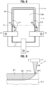
- the clamps K1 are temporarily released, and as shown in FIG. 10 , the jacket body 2 and the sealing body 3 in the first region R1 (see FIG. 3 ) are immovably clamped with the three clamps K1.
- the second primary joining process is a process to perform friction stir welding to the first butted portion J1 in the second region R2 (see FIG. 3 ).
- three sections - comprising an insertion section, an original section and a leaving section - are frictionally stirred continuously.
- the insertion section extends from a starting position SP2 to a middle point S3.
- the original section extends from the middle point S3 to the other middle point S4, both located on the set moving track L1.
- the leaving section extends from the other middle point S4 to an ending position EP2.
- the starting position SP2 is set on an inner side relative to the set moving track L1 on the front face 3a of the sealing body 3.
- the middle point S3 is set on the first region R1 side (see FIG.
- the middle point S3 is set at a position where an angle ⁇ 3 defined by a line segment connecting the starting position SP2 and the middle point S3 and the set moving track L1 is an obtuse angle.
- the stirring pin F2 After the stirring pin F2 reaches the middle point S3, the stirring pin F2 continuously shifts to the original section for friction stir welding.
- the rotary tool F In the original section, the rotary tool F is moved such that the axis C of the stirring pin F2 is overlapped with the set moving track L1.
- friction stirring is performed in the same manner as that in the original section in the first primary joining process.
- the stirring pin F2 continuously shifts to the leaving section.
- the stirring pin F2 is gradually moved upward while being moved from the other middle point S4 toward the ending position EP2, at which position the stirring pin F2 is made to leave the sealing body 3.
- the rotary tool F is moved to the ending position EP1, while its rotational speed in the leaving section is gradually reduced from the rotational speed of the rotary tool F in the original section.
- the conditions in the leaving section in the second primary joining process are the same as those in the leaving section in the first main joining process.
- the ending position EP2 is set on the peripheral wall end face 11a of the peripheral wall section 11 outside the set moving track L1.
- the ending position EP2 is set at a position where an angle ⁇ 4 defined by a line segment connecting the ending position EP2 and the other middle point S4 and the set moving track L1 in the peripheral wall end face 11a of the peripheral wall section 11 is an obtuse angle.
- a plasticized region W2 is formed along the moving track of the rotary tool F.
- the joined body 1 is formed by the above-described processes.
- the rotary tool F in the leaving section where the rotary tool F is made to leave the jacket body (first metal member) 2 with higher hardness, the rotary tool F is removed while gradually decreasing the rotational speed from that in the original section.
- This can reduce frictional heat input to the jacket body 2, so that cracking on the jacket body 2 and generation of burrs can be suppressed.
- a good surface finish is achieved on the peripheral wall end face 11a of the jacket body 2. In other words, an excellent surface finish for the joined body 1 can be provided.
- removing the rotary tool F while reducing its rotational speed makes it possible to suppress friction between the jacket body 2 (first metal member) with higher hardness and the rotary tool F, so that damage to the rotary tool F can be prevented.
- this manufacturing method it is possible to remove the rotary tool F from the jacket body (first metal member) 2 with higher hardness, and the removal hole is formed in the first metal member.
- no removal hole is formed in the second metal member. This can eliminate the need to repair the removal hole in the second metal member, so that electronic components can be installed on the second metal member without requiring the pre-processing to repair the removal hole after friction stirring.
- the rotational speed of the rotary tool F may be set as desired. However, if the rotational speed of the rotary tool F for performing friction stir welding at the first butted portion J1 in the original section is assumed to be 100%, it is preferable that the rotational speed in the leaving section be set to 10% or higher and 50% or lower.
- the rotational speed in the leaving section is gradually reduced from that in the original section, it is preferable that the rotational speed of the rotary tool F in the original section for performing friction stir welding at the first butted portion J1 be set to 5,000 rpm or higher and 20,000 rpm or lower, and that the rotational speed in the leaving section be set to 1,000 rpm or higher and 8,000 rpm or lower.
- the rotational speed of the rotary tool F may be set as desired. However, setting the rotational speed of the rotary tool F as described above makes it possible to more precisely achieve the above-described effects.
- the second aluminum alloy on the sealing body 3 side in the first butted portion J1 is mainly stirred to be plastically fluidized because of frictional heat generated by the friction between the sealing body 3 and the stirring pin F2.
- the step side face 12b and the side face 3c of the sealing body 3 in the first butted portion J1 are joined together.
- the outer circumferential face of the stirring pin F2 is slightly brought in contact with the step side face 12b of the jacket body 2, the mixing amount of the first aluminum alloy into the sealing body 3 from the jacket body 2 can be reduced as much as possible.
- the second aluminum alloy on the sealing body 3 side is mainly frictionally stirred. For this reason, the decrease in the joining strength can be suppressed.
- the unbalance between one side and the other side with respect to the axis C of the stirring pin F2, which is caused by material resistances to the stirring pin F2, can be reduced as much as possible.
- plastically fluidized materials are frictionally stirred in the well balanced state, so that the decrease in the joining strength can be suppressed.
- metal shortage of the joined portion can be prevented by increasing the thickness of the sealing body 3.
- the stirring pin F2 is gradually inserted to the predetermined depth while the rotary tool F is moved from the starting positions SP1, SP2 to positions to overlap with the set moving track L1. This can prevent excessive frictional heat that is generated when the rotary tool F stops on the set moving track L1.
- the stirring pin F2 is gradually pulled upward from the predetermined depth while the rotary tool F is moved from the set moving track L1 to the ending positions EP1, EP2, and is made to leave. This can prevent excessive frictional heat that is generated when the rotary tool F stops on the set moving track L1.
- the stirring pin F2 is slightly in contact with both the step side face 12b and the step bottom face 12a, the first butted portion J1 and the second butted portion J2 can be reliably joined. Furthermore, since the stirring pin F2 is slightly brought in contact with the step side face 12b and the step bottom face 12a, the mixing amount of the first aluminum alloy that is mixed from the jacket body 2 into the sealing body 3 can be reduced as much as possible.
- the starting positions SP1, SP2 may be appropriately set.
- the rotary tool F smoothly shifts to the original section without reducing the moving speed of the rotary tool F at the middle points S1, S3. This can prevent excessive frictional heat from being generated by stopping or reducing of the moving speed of the rotary tool F on the set moving track L1.
- the ending positions EP1, EP2 may be appropriately set.
- the rotary tool F smoothly shifts to the leaving section without reducing the moving speed of the rotary tool F at the other middle points S2, S4. This can prevent excessive frictional heat from being generated by stopping or reducing of the moving speed of the rotary tool F on the set moving track L1.
- a rotational direction and a moving (advancing) direction of the rotary tool F may be appropriately set.
- the rotational direction and the moving (advancing) direction of the rotary tool F are set such that within the plasticized region W1 formed along the moving track of the rotary tool F, the jacket body 2 side is a shear side, and the sealing body 3 side is a flow side.
- the jacket body 2 side is a shear side
- stirring action around the first butted portion J1 due to the stirring pin F2 is enhanced, so that temperature rise in the first butted portion J1 can be expected. Therefore, in the first butted portion J1, the step side face 12b and the side face 3c of the sealing body 3 can be reliably joined together.
- a shear side means a side where the relative speed of the outer peripheral speed of the rotary tool, relative to a portion to be joined, is a speed obtained by adding the moving speed of the rotary tool and a tangential speed of the outer periphery of the rotary tool.
- a flow side means a side where the relative speed of the rotary tool, relative to the portion to be joined, is low because the rotary tool is rotated in the direction opposite to the moving direction of the rotary tool.
- the first aluminum alloy of the jacket body 2 is of a harder material than the second aluminum alloy of the sealing body 3. For this reason, the durability of the joined body 1 can be enhanced. It is preferable that the first aluminum alloy of the jacket body 2 is of an aluminum alloy casting material and the second aluminum alloy of the sealing body 3 be of an aluminum alloy expansible material. If the first aluminum alloy is of, for example, the aluminum alloy casting material based on Al-Si-Cu such as JISH5302 ADC12, castability, strength and machinability of the jacket body 2 can be enhanced. Further, if the second aluminum alloy is of, for example, a material based on JIS A1000 or A6000, workability and thermal conductivity of the jacket body 2 can be enhanced.
- the plasticized region W1 formed through the first primary joining process and the plasticized region W2 formed through the second primary joining process are overlapped at respective end portions on the set moving track L1, so that the airtightness and the watertightness can be more reliably enhanced.
- the stirring pin F2 can be brought in uniform contact with the whole of the step side face 12b in the height direction thereof.
- friction stir welding can be performed in a balanced manner.
- friction stirring is performed in the state that a base portion of the stirring pin F2 of the rotary tool F is exposed, so that the load to be acted on the friction stir device can be reduced.
- the first modification differs from the above embodiment in the positions of the starting positions SP1, SP2 in the primary joining process.
- the description of the first modification will focus on the parts that are different from those of the above embodiment.
- the starting positions SP11, SP12 are set on the set moving track L1 in the primary joining process.
- the other middle point S4 in the second primary joining process is set on the set moving track L1 on the side of the first region R1 (see FIG. 3 ) rather than the starting position SP11.
- three sections - comprising an insertion section, an original section and a leaving section - are frictionally stirred continuously.
- the insertion section extends from a starting position SP11 to the middle point S1.
- the original section extends from the middle point S1 to the other middle point S2, both located on the set moving track L1.
- the leaving section extends from the other middle point S2 to the ending position EP1.
- a plasticized region W11 is formed along the moving track of the rotary tool F.
- three sections - comprising an insertion section, an original section and a leaving section - are frictionally stirred continuously.
- the insertion section extends from a starting position SP12 to the middle point S3.
- the original section extends from the middle point S3 to the other middle point S4, both located on the set moving track L1.
- the leaving section extends from the other middle point S4 to the ending position EP2.
- the rotary tool F is moved from the middle point S1 to the other middle point S4 such that the stirring pin F2 passes through the starting position SP11.
- a plasticized region W12 is formed along the moving track of the rotary tool F. Accordingly, in the original section in the second primary joining process, an insertion hole formed at the starting position SP11 can be filled by the plasticized region W12.
- the rotational speed of the rotary tool F for friction stir welding may be set as desired.
- the rotational speed of the rotary tool F may be gradually lowered from a rotational speed higher than that of the rotary tool F in the original section.
- the second modification differs from the above embodiment in the positions of the starting positions SP21, SP22 in the primary joining process.
- the description of the second modification will focus on the parts that are different from those of the above embodiment.
- the starting positions SP21, SP22 are set on the peripheral wall end face 11a of the peripheral wall section 11 in the primary joining process.
- the starting positions SP21, SP22 are set on the peripheral wall end face 11a of the peripheral wall section 11 at positions outside the set moving track L1.
- the starting positions SP21, SP22 are set at positions where an angle ⁇ 21. ⁇ 22 defined by a line segment connecting the starting position SP21, SP22 and the middle point S1, S2 and the set moving track L1 is an obtuse angle.
- three sections - comprising an insertion section, an original section and a leaving section - are frictionally stirred continuously.
- the insertion section extends from a starting position SP21 to the middle point S1.
- the original section extends from the middle point S1 to the other middle point S2, both located on the set moving track L1.
- the leaving section extends from the other middle point S2 to the ending position EP1.
- a plasticized region W21 is formed along the moving track of the rotary tool F.
- three sections - comprising an insertion section, an original section and a leaving section - are frictionally stirred continuously.
- the insertion section extends from a starting position SP22 to the middle point S3.
- the original section extends from the middle point S3 to the other middle point S4, both located on the set moving track L1.
- the leaving section extends from the other middle point S4 to the ending position EP2.
- a plasticized region W22 is formed along the moving track of the rotary tool F.
- the stirring pin F2 is gradually inserted such that it reaches a "predetermined depth" set in advance at least by the time it reaches from the starting positions SP21, SP22 to the middle points S1, S2. That is, the rotary tool F is gradually lowered while it is being moved to the set moving track L1 without remaining in one position. At this time, the rotary tool F may be moved to the middle point S1, while its rotational speed in the insertion section is gradually increased from a rotational speed lower than the rotational speed of the rotary tool F in the original section.
- the rotational speed in the insertion section can be set to 10% or higher and 50% or lower.
- the rotational speed in the insertion section relative to the rotational speed of the rotary tool F for performing friction stir welding at the first butted portion J1 is preferably 15% or higher, more preferably 20% or higher, and even more preferably 25% or higher, and also preferably 45% or lower, more preferably 40% or lower, and even more preferably 35% or lower.
- the rotational speed of the rotary tool F can be set as desired. For example, it can be set to 1,000 rpm or higher, and 8,000 rpm or lower.
- the rotational speed of the rotary tool F in the insertion section is preferably 2,000 rpm or higher, more preferably 3,000 rpm or higher, and further more preferably 4,000 rpm or higher, and also preferably 7,000 rpm or lower, more preferably 6,000 rpm or lower, and further more preferably 5,000 rpm or lower.
- the insertion hole is formed in the jacket body 2 (first metal member) and no insertion hole is formed in the sealing body (second metal member) 3.
- This can eliminate the need to repair the insertion hole in the second metal member, so that electronic components can be installed on the second metal member without requiring the pre-processing to repair the insertion hole after friction stirring.
- the plasticized region formed on the sealing body 3 can be made smaller as compared with that formed in the above embodiment. As a result, it is possible to further increase the degree of freedom in the design of the joined body produced by friction stir welding the first metal member and the second metal member as well as to further improve the productivity.
- friction stirring is performed while clamping the jacket body and the sealing body 3 twice.
- friction stirring may also be performed while clamping the jacket body 2 and the sealing body 3 once or more than three times.
- the third modification differs from the above embodiment in that clamping in the primary joining process is performed at one time without dividing it into two steps. The description of the third modification will focus on the parts that are different from those of the above embodiment.
- three sections - comprising an insertion section, an original section and a leaving section - are frictionally stirred continuously.
- the insertion section extends from the starting position SP1 to the middle point S1.
- the original section extends around the periphery of the sealing body 3 from the middle point S1 to the other middle point S4, both located on the set moving track L1.
- the leaving section extends from the other middle point S4 to the ending position EP2.
- a plasticized region W31 is formed along the moving track of the rotary tool F. In this instance, friction stirring is performed while clamping the jacket body 2 and the sealing body 3 at multiple positions. Clamping is temporarily released when the rotary tool F approaches, and then re-clamped after the rotary tool F passes through the clamped position.
- the fourth modification differs from the above embodiment in the position of the starting position SP11 in the primary joining process and in that the primary joining process is performed in a single step.
- the description of the fourth modification will focus on the parts that are different from those of the above embodiment.
- the starting position SP11 is set on the set moving track L1 in the primary joining process.
- the other middle point S4 in the primary joining process is set on the set moving track L1 on the side of the first region R1 (see FIG. 3 ) rather than the starting position SP11.
- three sections - comprising an insertion section, an original section and a leaving section - are frictionally stirred continuously.
- the insertion section extends from the starting position SP11 to the middle point S1.
- the original section extends around the periphery of the sealing body 3 from the middle point S1 to the other middle point S4, both located on the set moving track L1.
- the leaving section extends from the other middle point S4 to the ending position EP2.
- the rotary tool F is moved from the middle point S1 to the other middle point S4 such that the stirring pin F2 passes through the starting position SP11.
- a plasticized region W41 is formed along the moving track of the rotary tool F.
- an insertion hole formed at the starting position SP11 can be filled by the plasticized region W41.
- friction stirring is performed while clamping the jacket body 2 and the sealing body 3 at multiple positions. Clamping is temporarily released when the rotary tool F approaches, and then re-clamped after the rotary tool F passes through the clamped position.
- the rotational speed of the rotary tool F for friction stir welding may be set as desired.
- the rotational speed of the rotary tool F may be gradually lowered from a rotational speed higher than that of the rotary tool F in the original section.
- the rotary tool F is moved such that before the rotary tool F is made to leave the jacket body (first metal member) 2 at the ending position EP2, the stirring pin F2 passes through the starting position SP11. Accordingly, in this modification, the one insertion hole formed at the starting position SP1 can be filled, while performing friction stir welding along the set moving track L1. Therefore, since no insertion holes remain on the set moving track L1, it is possible to further increase design freedom and to further improve the productivity.
- the rotary tool F is gradually inserted while being moved.
- the rotary tool F may be moved after being inserted into a predetermined position at the starting positions SP1, SP2.
- the rotary tool F is gradually pulled upward (made to leave) while being moved.
- the rotary tool F may be moved upward and removed vertically at the ending positions EP1, EP2 after it is moved to the ending positions EP1, EP2 at a predetermined depth (constant depth).
- a provisional joining process may be carried out, in which the jacket body 2 and the sealing body 3 are provisionally joined. This makes it possible to prevent misalignment between the jacket body 2 and the sealing body 3 in the primary joining process.
- friction stirring may be performed using a rotary tool dedicated for provisional joining, or welding may be used.
- the moving track of the rotary tool F may be set to draw a curved line (for example, an arc) when viewed in a plan view. This allows for a smooth transition from the insertion section to the original section or from the original section to the leaving section.
- friction stir welding is performed with the use of the rotary tool F by inserting only the stirring pin F2 into the jacket body 2 and the sealing body 3.
- the use of the rotary tool and the manner of friction stir welding are not limited to this specific embodiment.
- friction stir welding may be performed using a rotary tool equipped with a shoulder and a stirring pin hanging down from the shoulder.
- friction stir welding may be performed by inserting the stirring pin into the jacket body 2 and the sealing body 3 while the shoulder is in contact with the peripheral wall portion 11 of the jacket body 2 and the front face 3a of the sealing body 3.
Landscapes
- Engineering & Computer Science (AREA)
- Mechanical Engineering (AREA)
- Pressure Welding/Diffusion-Bonding (AREA)
Applications Claiming Priority (2)
| Application Number | Priority Date | Filing Date | Title |
|---|---|---|---|
| JP2021180854A JP7775642B2 (ja) | 2021-11-05 | 2021-11-05 | 接合体の製造方法 |
| PCT/JP2022/037101 WO2023079891A1 (ja) | 2021-11-05 | 2022-10-04 | 接合体の製造方法 |
Publications (2)
| Publication Number | Publication Date |
|---|---|
| EP4424451A1 true EP4424451A1 (de) | 2024-09-04 |
| EP4424451A4 EP4424451A4 (de) | 2026-04-15 |
Family
ID=86241456
Family Applications (1)
| Application Number | Title | Priority Date | Filing Date |
|---|---|---|---|
| EP22889715.3A Pending EP4424451A4 (de) | 2021-11-05 | 2022-10-04 | Verfahren zur herstellung eines verbundenen körpers |
Country Status (6)
| Country | Link |
|---|---|
| US (1) | US20250041965A1 (de) |
| EP (1) | EP4424451A4 (de) |
| JP (1) | JP7775642B2 (de) |
| CN (1) | CN118139714A (de) |
| TW (1) | TW202327771A (de) |
| WO (1) | WO2023079891A1 (de) |
Families Citing this family (2)
| Publication number | Priority date | Publication date | Assignee | Title |
|---|---|---|---|---|
| JP2025110529A (ja) * | 2024-01-16 | 2025-07-29 | 日本軽金属株式会社 | 接合体の製造方法 |
| JP2025110528A (ja) * | 2024-01-16 | 2025-07-29 | 日本軽金属株式会社 | 接合体の製造方法 |
Family Cites Families (18)
| Publication number | Priority date | Publication date | Assignee | Title |
|---|---|---|---|---|
| JP3575748B2 (ja) * | 2000-03-06 | 2004-10-13 | 株式会社日立製作所 | 摩擦攪拌接合方法 |
| JP3471338B2 (ja) * | 2001-07-30 | 2003-12-02 | 川崎重工業株式会社 | 摩擦攪拌接合装置 |
| US6913186B2 (en) * | 2003-09-11 | 2005-07-05 | The Boeing Company | Apparatus and method for friction stir welding with a variable speed pin |
| US7416102B1 (en) * | 2004-10-22 | 2008-08-26 | Edison Welding Institute, Inc. | Method of friction stir welding and multi-section faced shoulderless retractable variable penetration friction stir welding tool for same |
| US7703654B2 (en) * | 2004-11-17 | 2010-04-27 | The Boeing Company | Counter-rotating spindle for friction stir welding |
| CN102303183B (zh) * | 2006-10-02 | 2014-01-29 | 日本轻金属株式会社 | 接合方法 |
| JP5262822B2 (ja) * | 2009-02-23 | 2013-08-14 | 日本軽金属株式会社 | 液冷ジャケットの製造方法 |
| JP5631162B2 (ja) * | 2010-11-16 | 2014-11-26 | カルソニックカンセイ株式会社 | 摩擦攪拌接合方法 |
| JP6372515B2 (ja) * | 2015-08-26 | 2018-08-15 | 日本軽金属株式会社 | 液冷ジャケットの製造方法及び液冷ジャケット |
| CN110300636B (zh) * | 2017-04-18 | 2021-08-03 | 日本轻金属株式会社 | 液冷套的制造方法 |
| JP6885285B2 (ja) * | 2017-09-28 | 2021-06-09 | 日本軽金属株式会社 | 液冷ジャケットの製造方法 |
| US11794271B2 (en) * | 2018-07-19 | 2023-10-24 | Nippon Light Metal Company, Ltd. | Method for manufacturing liquid-cooled jacket |
| JP7003862B2 (ja) * | 2018-07-19 | 2022-01-21 | 日本軽金属株式会社 | 液冷ジャケットの製造方法 |
| EP3854512A4 (de) * | 2018-09-18 | 2022-06-22 | Nippon Light Metal Company, Ltd. | Verfahren zur herstellung eines flüssigkeitskühlmantels |
| JP2020131263A (ja) | 2019-02-22 | 2020-08-31 | 日本軽金属株式会社 | 液冷ジャケットの製造方法 |
| WO2020170488A1 (ja) * | 2019-02-22 | 2020-08-27 | 日本軽金属株式会社 | 液冷ジャケットの製造方法 |
| JP2020175396A (ja) | 2019-04-15 | 2020-10-29 | 日本軽金属株式会社 | 液冷ジャケットの製造方法 |
| JP2021112757A (ja) | 2020-01-16 | 2021-08-05 | 日本軽金属株式会社 | 液冷ジャケットの製造方法 |
-
2021
- 2021-11-05 JP JP2021180854A patent/JP7775642B2/ja active Active
-
2022
- 2022-10-04 WO PCT/JP2022/037101 patent/WO2023079891A1/ja not_active Ceased
- 2022-10-04 EP EP22889715.3A patent/EP4424451A4/de active Pending
- 2022-10-04 CN CN202280071236.7A patent/CN118139714A/zh active Pending
- 2022-10-04 US US18/706,708 patent/US20250041965A1/en active Pending
- 2022-10-18 TW TW111139397A patent/TW202327771A/zh unknown
Also Published As
| Publication number | Publication date |
|---|---|
| WO2023079891A1 (ja) | 2023-05-11 |
| EP4424451A4 (de) | 2026-04-15 |
| TW202327771A (zh) | 2023-07-16 |
| CN118139714A (zh) | 2024-06-04 |
| JP2023069179A (ja) | 2023-05-18 |
| US20250041965A1 (en) | 2025-02-06 |
| JP7775642B2 (ja) | 2025-11-26 |
Similar Documents
| Publication | Publication Date | Title |
|---|---|---|
| US20240009753A1 (en) | Method for manufacturing liquid-cooled jacket | |
| US11559850B2 (en) | Method for manufacturing liquid-cooled jacket | |
| KR101250708B1 (ko) | 접합 방법 | |
| EP4424451A1 (de) | Verfahren zur herstellung eines verbundenen körpers | |
| EP3260230B1 (de) | Verbindungsverfahren und verfahren zur herstellung eines verbundstoffwalzmaterials | |
| EP3878593A1 (de) | Verfahren zur herstellung eines flüssigkeitsgekühlten mantels und reibrührschweissverfahren | |
| US11707799B2 (en) | Joining method | |
| EP3711892A1 (de) | Verbindungsverfahren | |
| US12151303B2 (en) | Method for manufacturing liquid-cooling jacket and friction stir welding method | |
| US20210276120A1 (en) | Liquid cooling jacket manufacturing method | |
| US20150328725A1 (en) | Conical pins for the structural repair of defects | |
| EP3903987B1 (de) | Verbindungsverfahren | |
| JP7003861B2 (ja) | 液冷ジャケットの製造方法 | |
| JP7003862B2 (ja) | 液冷ジャケットの製造方法 | |
| WO2020059198A1 (ja) | 液冷ジャケットの製造方法 | |
| US12202067B2 (en) | Method for manufacturing liquid-cooling jacket and friction stir welding method | |
| JP6927134B2 (ja) | 液冷ジャケットの製造方法 | |
| JP2021112757A (ja) | 液冷ジャケットの製造方法 | |
| WO2020170488A1 (ja) | 液冷ジャケットの製造方法 | |
| WO2021145000A1 (ja) | 液冷ジャケットの製造方法 | |
| WO2019202754A1 (ja) | 液冷ジャケットの製造方法 | |
| JP2019111547A (ja) | 液冷ジャケットの製造方法 |
Legal Events
| Date | Code | Title | Description |
|---|---|---|---|
| STAA | Information on the status of an ep patent application or granted ep patent |
Free format text: STATUS: THE INTERNATIONAL PUBLICATION HAS BEEN MADE |
|
| PUAI | Public reference made under article 153(3) epc to a published international application that has entered the european phase |
Free format text: ORIGINAL CODE: 0009012 |
|
| STAA | Information on the status of an ep patent application or granted ep patent |
Free format text: STATUS: REQUEST FOR EXAMINATION WAS MADE |
|
| 17P | Request for examination filed |
Effective date: 20240528 |
|
| AK | Designated contracting states |
Kind code of ref document: A1 Designated state(s): AL AT BE BG CH CY CZ DE DK EE ES FI FR GB GR HR HU IE IS IT LI LT LU LV MC ME MK MT NL NO PL PT RO RS SE SI SK SM TR |
|
| DAV | Request for validation of the european patent (deleted) | ||
| DAX | Request for extension of the european patent (deleted) | ||
| A4 | Supplementary search report drawn up and despatched |
Effective date: 20260313 |
|
| RIC1 | Information provided on ipc code assigned before grant |
Ipc: B23K 20/12 20060101AFI20260310BHEP |