EP4421160A2 - Siebwechselvorrichtung sowie system und verfahren zur reduzierung der grösse von biologischem gewebe damit - Google Patents
Siebwechselvorrichtung sowie system und verfahren zur reduzierung der grösse von biologischem gewebe damit Download PDFInfo
- Publication number
- EP4421160A2 EP4421160A2 EP22818176.4A EP22818176A EP4421160A2 EP 4421160 A2 EP4421160 A2 EP 4421160A2 EP 22818176 A EP22818176 A EP 22818176A EP 4421160 A2 EP4421160 A2 EP 4421160A2
- Authority
- EP
- European Patent Office
- Prior art keywords
- screen
- syringe
- connector
- wall
- living tissue
- Prior art date
- Legal status (The legal status is an assumption and is not a legal conclusion. Google has not performed a legal analysis and makes no representation as to the accuracy of the status listed.)
- Pending
Links
Images


Classifications
-
- C—CHEMISTRY; METALLURGY
- C12—BIOCHEMISTRY; BEER; SPIRITS; WINE; VINEGAR; MICROBIOLOGY; ENZYMOLOGY; MUTATION OR GENETIC ENGINEERING
- C12M—APPARATUS FOR ENZYMOLOGY OR MICROBIOLOGY; APPARATUS FOR CULTURING MICROORGANISMS FOR PRODUCING BIOMASS, FOR GROWING CELLS OR FOR OBTAINING FERMENTATION OR METABOLIC PRODUCTS, i.e. BIOREACTORS OR FERMENTERS
- C12M23/00—Constructional details, e.g. recesses, hinges
- C12M23/02—Form or structure of the vessel
- C12M23/10—Petri dish
-
- A—HUMAN NECESSITIES
- A61—MEDICAL OR VETERINARY SCIENCE; HYGIENE
- A61L—METHODS OR APPARATUS FOR STERILISING MATERIALS OR OBJECTS IN GENERAL; DISINFECTION, STERILISATION OR DEODORISATION OF AIR; CHEMICAL ASPECTS OF BANDAGES, DRESSINGS, ABSORBENT PADS OR SURGICAL ARTICLES; MATERIALS FOR BANDAGES, DRESSINGS, ABSORBENT PADS OR SURGICAL ARTICLES
- A61L27/00—Materials for grafts or prostheses or for coating grafts or prostheses
- A61L27/36—Materials for grafts or prostheses or for coating grafts or prostheses containing ingredients of undetermined constitution or reaction products thereof, e.g. transplant tissue, natural bone, extracellular matrix
-
- A—HUMAN NECESSITIES
- A61—MEDICAL OR VETERINARY SCIENCE; HYGIENE
- A61M—DEVICES FOR INTRODUCING MEDIA INTO, OR ONTO, THE BODY; DEVICES FOR TRANSDUCING BODY MEDIA OR FOR TAKING MEDIA FROM THE BODY; DEVICES FOR PRODUCING OR ENDING SLEEP OR STUPOR
- A61M1/00—Suction or pumping devices for medical purposes; Devices for carrying-off, for treatment of, or for carrying-over, body-liquids; Drainage systems
-
- B—PERFORMING OPERATIONS; TRANSPORTING
- B02—CRUSHING, PULVERISING, OR DISINTEGRATING; PREPARATORY TREATMENT OF GRAIN FOR MILLING
- B02C—CRUSHING, PULVERISING, OR DISINTEGRATING IN GENERAL; MILLING GRAIN
- B02C19/00—Other disintegrating devices or methods
-
- C—CHEMISTRY; METALLURGY
- C12—BIOCHEMISTRY; BEER; SPIRITS; WINE; VINEGAR; MICROBIOLOGY; ENZYMOLOGY; MUTATION OR GENETIC ENGINEERING
- C12M—APPARATUS FOR ENZYMOLOGY OR MICROBIOLOGY; APPARATUS FOR CULTURING MICROORGANISMS FOR PRODUCING BIOMASS, FOR GROWING CELLS OR FOR OBTAINING FERMENTATION OR METABOLIC PRODUCTS, i.e. BIOREACTORS OR FERMENTERS
- C12M23/00—Constructional details, e.g. recesses, hinges
- C12M23/02—Form or structure of the vessel
- C12M23/12—Well or multiwell plates
-
- C—CHEMISTRY; METALLURGY
- C12—BIOCHEMISTRY; BEER; SPIRITS; WINE; VINEGAR; MICROBIOLOGY; ENZYMOLOGY; MUTATION OR GENETIC ENGINEERING
- C12M—APPARATUS FOR ENZYMOLOGY OR MICROBIOLOGY; APPARATUS FOR CULTURING MICROORGANISMS FOR PRODUCING BIOMASS, FOR GROWING CELLS OR FOR OBTAINING FERMENTATION OR METABOLIC PRODUCTS, i.e. BIOREACTORS OR FERMENTERS
- C12M23/00—Constructional details, e.g. recesses, hinges
- C12M23/50—Means for positioning or orientating the apparatus
-
- C—CHEMISTRY; METALLURGY
- C12—BIOCHEMISTRY; BEER; SPIRITS; WINE; VINEGAR; MICROBIOLOGY; ENZYMOLOGY; MUTATION OR GENETIC ENGINEERING
- C12M—APPARATUS FOR ENZYMOLOGY OR MICROBIOLOGY; APPARATUS FOR CULTURING MICROORGANISMS FOR PRODUCING BIOMASS, FOR GROWING CELLS OR FOR OBTAINING FERMENTATION OR METABOLIC PRODUCTS, i.e. BIOREACTORS OR FERMENTERS
- C12M25/00—Means for supporting, enclosing or fixing the microorganisms, e.g. immunocoatings
- C12M25/02—Membranes; Filters
- C12M25/04—Membranes; Filters in combination with well or multiwell plates, i.e. culture inserts
-
- C—CHEMISTRY; METALLURGY
- C12—BIOCHEMISTRY; BEER; SPIRITS; WINE; VINEGAR; MICROBIOLOGY; ENZYMOLOGY; MUTATION OR GENETIC ENGINEERING
- C12M—APPARATUS FOR ENZYMOLOGY OR MICROBIOLOGY; APPARATUS FOR CULTURING MICROORGANISMS FOR PRODUCING BIOMASS, FOR GROWING CELLS OR FOR OBTAINING FERMENTATION OR METABOLIC PRODUCTS, i.e. BIOREACTORS OR FERMENTERS
- C12M33/00—Means for introduction, transport, positioning, extraction, harvesting, peeling or sampling of biological material in or from the apparatus
- C12M33/04—Means for introduction, transport, positioning, extraction, harvesting, peeling or sampling of biological material in or from the apparatus by injection or suction, e.g. using pipettes, syringes, needles
-
- C—CHEMISTRY; METALLURGY
- C12—BIOCHEMISTRY; BEER; SPIRITS; WINE; VINEGAR; MICROBIOLOGY; ENZYMOLOGY; MUTATION OR GENETIC ENGINEERING
- C12M—APPARATUS FOR ENZYMOLOGY OR MICROBIOLOGY; APPARATUS FOR CULTURING MICROORGANISMS FOR PRODUCING BIOMASS, FOR GROWING CELLS OR FOR OBTAINING FERMENTATION OR METABOLIC PRODUCTS, i.e. BIOREACTORS OR FERMENTERS
- C12M33/00—Means for introduction, transport, positioning, extraction, harvesting, peeling or sampling of biological material in or from the apparatus
- C12M33/12—Means for introduction, transport, positioning, extraction, harvesting, peeling or sampling of biological material in or from the apparatus by pressure
-
- C—CHEMISTRY; METALLURGY
- C12—BIOCHEMISTRY; BEER; SPIRITS; WINE; VINEGAR; MICROBIOLOGY; ENZYMOLOGY; MUTATION OR GENETIC ENGINEERING
- C12M—APPARATUS FOR ENZYMOLOGY OR MICROBIOLOGY; APPARATUS FOR CULTURING MICROORGANISMS FOR PRODUCING BIOMASS, FOR GROWING CELLS OR FOR OBTAINING FERMENTATION OR METABOLIC PRODUCTS, i.e. BIOREACTORS OR FERMENTERS
- C12M33/00—Means for introduction, transport, positioning, extraction, harvesting, peeling or sampling of biological material in or from the apparatus
- C12M33/14—Means for introduction, transport, positioning, extraction, harvesting, peeling or sampling of biological material in or from the apparatus with filters, sieves or membranes
-
- A—HUMAN NECESSITIES
- A61—MEDICAL OR VETERINARY SCIENCE; HYGIENE
- A61J—CONTAINERS SPECIALLY ADAPTED FOR MEDICAL OR PHARMACEUTICAL PURPOSES; DEVICES OR METHODS SPECIALLY ADAPTED FOR BRINGING PHARMACEUTICAL PRODUCTS INTO PARTICULAR PHYSICAL OR ADMINISTERING FORMS; DEVICES FOR ADMINISTERING FOOD OR MEDICINES ORALLY; BABY COMFORTERS; DEVICES FOR RECEIVING SPITTLE
- A61J1/00—Containers specially adapted for medical or pharmaceutical purposes
- A61J1/14—Details; Accessories therefor
- A61J1/20—Arrangements for transferring or mixing fluids, e.g. from vial to syringe
- A61J1/2003—Accessories used in combination with means for transfer or mixing of fluids, e.g. for activating fluid flow, separating fluids, filtering fluid or venting
- A61J1/2048—Connecting means
- A61J1/2058—Connecting means having multiple connecting ports
Definitions
- the present disclosure relates to a screen changing device, and a system and method of reducing the size of a living tissue using the screen changing device.
- the present disclosure relates to a screen changing device that changes any one screen, which reduces the size of a living tissue, to another screen to separate substance that can be used for regeneration treatment and cosmetic treatment from a living tissue, and a system and method of reducing the size of a living tissue using the screen changing device.
- Living tissues contain various tissues, cells, and substances that can be used for regeneration treatment and cosmetic treatment, so various methods are used to separate the tissues, cells, and substances.
- a method of decomposing and centrifugally separating a fat tissue generally using an enzyme is widely used for fat tissues, but there is no appropriate medical enzyme and enzymes that are used have toxicity, so there is controversy over the safety of substances obtained from decomposed fat tissues.
- a screen changing device has been disclosed in Korean Patent Application Publication No. 10-2020-0119695 .
- the background described above was kept or obtained by the inventor(s) in the process of deriving the invention and should not be considered as a well-known technology published before the filing of the present disclosure.
- An objective of the present disclosure is to provide a screen changing device that has a plurality of screens having through-holes, which reduce the size of a living tissue and have different sizes, and that can change any one screen in a channel to another screen without separating a container for pressing a living tissue and a container for keeping a living tissue.
- Another objective of the present disclosure is to provide a system and method of reducing the size of a living tissue using the screen changing device.
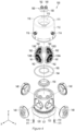
- a screen changing device includes: a first housing including a first base, an outer wall connected to the base, an inner wall connected to the first base and being opposite to the outer wall, a first space defined between the outer wall and the inner wall, a second space defined by the inner wall, a first connector disposed on the outer wall, and a second connector disposed on the inner wall and in the second space; a second housing including a second base, a supporting wall connected to the second base and disposed in the first space, and a plurality of recesses arranged in a circumferential direction of the supporting wall; and a plurality of screens disposed in the plurality of recesses, respectively, and configured to reduce a size of a living tissue, in which the second housing is configured to be rotated with respect to the first housing from a first configuration in which a first screen of the plurality of screens is aligned with the first connector and the second connector to a second configuration in which the first screen is not aligned with the first connector and the second connector and a second screen
- the screen changing device may further include a plurality of caps configured to retain the first screen, which corresponds to a first recess of the plurality of recesses, of the plurality of screens in the first recess.
- the screen changing device may further include a first sealing disposed between the plurality of caps and the outer wall.
- the screen changing device may further include a second sealing disposed between the supporting wall and the plurality of caps.
- the screen changing device may further include a third sealing disposed between the supporting wall and the inner wall.
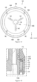
- the first connector may include: a first protrusion protruding from the outer wall away from the rotation axis; and a first passage defined in the first protrusion.
- the second connector may include: a second protrusion protruding from the inner wall; and a second passage defined in the second protrusion, and the second protrusion may include: a first extension extending from the inner wall toward the rotation axis; and a second extension extending from the first extension in an axial direction of the rotation axis.
- the screen changing device may further include: a guide groove disposed in the first housing; a ball disposed in the second housing; and an elastic member disposed between the guide groove and the ball, in which the ball and the elastic member may be configured to determine a position of the second housing with respect to the first housing.
- the first housing may further include: a third connector disposed on the outer wall; and a fourth connector disposed on the inner wall and in the second space.
- the screen changing device may further include a channel adapter configured to be coupled to the second connector.
- the screen changing device may further include an indicator showing a rotation direction of the second housing.
- the screen changing device may further include a body cap disposed between the inner wall and the second base.
- the first screen may include a first through-hole having a first shape and the second screen may include a second through-hole having a second shape different from the first shape.
- a system for reducing a size of a living tissue includes: a first syringe; a second syringe; and a screen changing device, in which the screen changing device includes: a first housing including a first base, an outer wall connected to the base, an inner wall connected to the first base and being opposite to the outer wall, a first space defined between the outer wall and the inner wall, a second space defined by the inner wall, a first connector disposed on the outer wall and configured to be connected with the first syringe, and a second connector disposed on the inner wall and in the second space and configured to be connected with the second syringe; a second housing including a second base, a supporting wall connected to the second base and disposed in the first space, and a plurality of recesses arranged in a circumferential direction of the supporting wall; a plurality of screens disposed in the plurality of recesses, respectively, and configured to reduce a size of a living tissue; and a plurality of caps
- a method of reducing a size of a living tissue using a screen changing device includes: a step of connecting a first syringe and a second syringe as a step of connecting the first syringe and the second syringe to the first connector and the second connector, respectively, in which at least one syringe of the first syringe and the second syringe is empty or includes a living tissue; a step of aligning a first screen of a plurality of screens with the first connector and the second connector; a step of alternately pressurising the first syringe and the second syringe; a step of aligning a second screen of a plurality of screens with the first connector and the second connector; and a step of alternately pressurising the first syringe and the second syringe.
- any one screen position in a channel can be changed to another one screen without separating a container (ex. a syringe) pressurising a living tissue and a container (ex. a syringe) accommodating a living tissue in a screen changing device including a plurality of screens for reducing the size of a living tissue.
- a screen corresponding to a container ex. a syringe
- pressurises or accommodates a living tissue to another screen by rotating a second housing with respect to a first housing without separating or replacing the container.
- Two syringes that are connected to the screen changing device make a set in a pair, and when a living tissue is pressurised in one syringe, the living tissue of which the size is reduced due to scratching or tearing through a screen is accommodated in another syringe. Accordingly, two connectors that are connected to a syringe also make a set in a pair.
- other spare connectors making a pair are provided so that another connector can be used when a channel through which a living tissue passes is clogged or damaged and cannot be used. That is, two sets of connectors making a pair are provided.
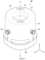
- the screen When a process of reducing the size of a living tissue using any one screen is finished, the screen should be changed to another screen having small through-holes, and in the present disclosure, an arrow is on the top surface of a first housing, so it is possible to easily change the screen to the screen having small through-holes by rotating the second housing in the direction of the arrow. That is, the arrow provides a guide making it possible to easily select a next screen in the process of reducing the size of a living tissue.
- Elastic members 172 and balls 173 are disposed in the second housing and guide grooves 112C corresponding to the elastic members and the balls are formed on the first housing, so the positions where the balls are fixed by the guide grooves are positions at which connectors of the first housing corresponds to screens of the second housing. That is, when the second housing is rotated to change a screen, a ball elastically supported by an elastic member is moved (positioned) in another groove at a next position (about 90 degrees), whereby a connector of the housing is accurately positioned at a position corresponding to a screen of the second housing.
- first”, “second”, “A”, “B”, “(a)”, and “(b)” can be used in the following description of the components of embodiments. These terms are provided only for discriminating components from other components and, the essence, sequence, or order of the components are not limited by the terms.
- a component is described as being “connected”, “combined”, or “coupled” with another component, it should be understood that the component may be connected or coupled to another component directly or with another component interposing therebetween.
- a screen changing device 100 may be configured to align any one screen (e.g., a first screen 130A) of a plurality of screens 130A, 130B, 130C, and 130D with a channel P and to align another one screen (e.g., a second screen 130B) with the channel P.
- the screen changing device 100 may include a first housing 110.
- the first housing 110 may be a relatively fixed part.
- the first housing 110 may include a first base 111.
- the first base 111 may include a first base surface 111A (e.g., a top) and a second base surface 111b (e.g., a bottom) opposite to the first base surface 111A.
- the first housing 110 may include an outer wall 112.
- the outer wall 112 may be connected to the outer edge of the first base 111.
- the outer wall 112 may include a first outer surface 112A (e.g., substantially perpendicularly) crossing each of the first base surface 111A and the second base surface 111B, and a first inner surface 112B being opposite to the first outer surface 112A and (e.g., substantially perpendicularly) crossing each of the first base surface 111A and the second base surface 111B.
- the first housing 110 may include an inner wall 113.
- the inner wall 113 may be connected to the inner edge of the first base 111.
- the inner wall 113 may include a second outer surface 113A (e.g., substantially perpendicularly) crossing each of the first base surface 111A and the second base surface 111B, and a second inner surface 113B being opposite to the second outer surface 113A and (e.g., substantially perpendicularly) crossing each of the first base surface 111A and the second base surface 111B.
- the second inner surface 113B may face the first inner surface 112B.
- the first inner surface 112B and the second inner surface 113B may be spaced apart from each other.
- a first space S1 may be defined between the first inner surface 112B of the outer wall 112 and the second inner surface 113B of the inner wall 113.
- the second outer surface 113A may define a second space S2.
- the first housing 110 may include a first connector 114.
- the first connector 114 may be disposed on the outer wall 112.
- the first connector 114 may include a first protrusion 114A protruding in one direction (e.g., +Y direction) from the first outer surface 112A of the outer wall 112.
- the first connector 114 may include a thread 114B formed on at least a portion of the outer surface of the first protrusion 114A.
- the first connector 114 may include a first passage P1 defined in the first protrusion 114A.
- the first passage P1 may be connected to the first space S1.
- the first housing 110 may include a second connector 115.
- the second connector 115 may be disposed on the inner wall 113.
- the second connector 115 may be disposed in the second space S2.
- the second connector 115 may include a second protrusion 115A protruding from the second outer surface 113A of the inner wall 113.
- the second protrusion 115A may include a first extension E1 extending in one direction (e.g., -Y direction) from the second outer surface 113A.
- the second protrusion 115A may include a second extension E2 extending from the first extension E1 in another direction (e.g., +Z direction) (e.g., substantially perpendicularly) crossing the extension direction of the first extension E1.
- the second connector 115 may include a second passage P2 defined in the second protrusion 115A.
- the second passage P2 may be connected to the second space S2.
- the second passage P2 may include a first extension passage P21 defined in the first extension E1.
- the first extension passage P21 may be connected to the first space S1.
- the second passage P2 may include a second extension passage P22 defined in the second extension E2.
- the second extension passage P22 may be connected to the first extension passage P21.
- the first passage P1, the first space S1, and the second passage P2 may form one channel P.
- the first housing 110 may include a third connector 116.
- the third connector 116 may be disposed on the outer wall 112.
- the third connector 116 may be spaced apart from the first connector 114 along the outer wall 112 in the circumferential direction of the first housing 110.
- the third connector 116 may include a third protrusion 116A protruding in one direction (e.g., +X direction) from the outer wall 112.
- the third connector 116 may include a thread 116B formed on at least a portion of the outer surface of the third protrusion 116A.
- the third connector 116 may include a third passage P3 defined in the third protrusion 116A.
- the third passage P3 may be connected to the first space S1.
- the first housing 110 may include a fourth connector 117.
- the fourth connector 117 may be disposed on the inner wall 113.
- the fourth connector 117 may be spaced apart from the second connector 115 along the inner wall 113 in the circumferential direction of the first housing 110.
- the fourth connector 117 may be disposed in the second space S2.
- the fourth connector 117 may include a fourth protrusion 117A protruding from the second outer surface 113A of the inner wall 113.
- the fourth protrusion 117A may include a third extension E3 extending in one direction (e.g., -X direction) from the second outer surface 113A.
- the fourth protrusion 117A may include a fourth extension E4 extending from the third extension E3 in another direction (e.g., +Z direction) (e.g., substantially perpendicularly) crossing the extension direction of the third extension E3.
- the fourth connector 117 may include a fourth passage P4 defined in the fourth protrusion 117A.
- the fourth passage P4 may be connected to the second space S2.
- the fourth passage P4 may include a third extension passage P41 defined in the third extension E3.
- the third extension passage P41 may be connected to the first space S1.
- the fourth passage P4 may include a fourth extension passage P42 defined in the fourth extension E4.
- the fourth extension passage P42 may be connected to the third extension passage P41.
- the first housing 110 may include a side recess 118.
- the side recess 118 may be formed at an end (e.g., a -Z-directional end) that is opposite to the end connected to the first base 111 of the ends of the inner wall 113.
- the side recess 118 may be formed on the second outer surface 113A toward the second inner surface 113B of the inner wall 113.
- the side recess 118 may extend in the circumferential direction of the second outer surface 113A.
- the first housing 110 may include a flange portion F1.
- the flange portion F1 may be radially formed from at least a portion of the outer wall 112.
- the first housing 110 may include a plurality of guide grooves 112C.
- the plurality of guide grooves 112C may be formed at the flange portion F1.
- the first housing 110 may include a first indicator AR1.
- the first indicator AR1 can show the rotation direction of a component (e.g., the second housing 120) with respect to the first housing 110 around a rotation axis A-A.
- the first indicator AR1 may include an arrow shape.
- the first indicator AR1 may be disposed on the first base surface 111A of the first base 111.
- the first indicator AR1 may include a plurality of arrow shapes arranged in the circumferential direction of the first housing 110.
- the screen changing device 100 may include a second housing 120.
- the first housing 120 may be a relatively rotating part.
- the second housing 120 may be configured to rotate about the rotation axis A-A with respect to the first housing 110.
- the second housing 120 may include a second base 121.
- the second base 121 may include a third base surface 121A (e.g., a top), a fourth base 121B (e.g., a bottom) opposite to the third base 121A, and a side base surface 121C between the third base surface 121A and the fourth base surface 121B.
- the second base 121 may include a concave portion 121D.
- the concave portion 121D may be formed on at least a portion of the fourth base surface 121B toward the third base surface 121A (e.g., in the +Z direction).
- the second base 121 may include a plurality of holes H.
- the holes H may be formed between the third base surface 121A and the fourth base surface 121B.
- the second housing 120 may include a supporting wall 122.
- the supporting wall 122 may extend in one direction (e.g., +Z direction) from the third base surface 121A of the second base 121.
- the supporting wall 122 may include an outer supporting surface 122B connected to the outer edge of a base supporting surface 122A and (e.g., substantially perpendicularly) crossing a base supporting surface 122A, and an inner supporting surface 122C connected to the inner edge of the base supporting surface 122A, e.g., substantially perpendicularly) crossing the base supporting surface 122A, and being opposite to the outer supporting surface 122B.
- the supporting wall 122 may be disposed in the first space S1.
- the supporting wall 122 may be surrounded by the base 111, the inner wall 113, and the outer wall 112. An end of the inner wall 113 and an end of the outer wall 112 may be disposed on the third base surface 121A.
- the base supporting surface 122A may face the second base surface 111B.
- the base supporting surface 122A may be in contact with the second base surface 111B.
- the outer supporting surface 122B may face the first inner surface 112B.
- the outer supporting surface 122B may be in contact with the first inner surface 112B.
- the inner supporting surface 122C may face the second inner surface 113B.
- the inner supporting surface 122C may be in contact with the second inner surface 113B.
- the inner supporting surface 122C may define a third space S3.
- the inner wall 113 may be disposed in the third space S3.
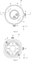
- the second housing 120 may include a plurality of recesses 123.
- the plurality of recesses 123 may be arranged in the circumferential direction of the supporting wall 122.
- four recesses 123 may be spaced about 90 degrees apart from each other around a rotation axis in the circumferential direction of the second housing 120.
- the plurality of recesses 123 may be formed on the outer supporting surface 122B toward the inner supporting surface 122C.
- the plurality of recesses 123 each may include a recess bottom surface 123A.
- the plurality of recesses 123 each may include a recess side surface 123B connecting the recess bottom surface 123A and the outer supporting surface 122B.
- the recess side surface 123B may (e.g., substantially perpendicularly) cross the recess bottom surface 123A and/or the outer supporting surface 122B.
- the plurality of recesses 123 each may include an opening 123C.
- the opening 123C may be disposed on the recess bottom surface 123A.
- the openings 123C may form a portion of the channel P.
- the channel P may be defined to continue from the first passage P1 defined in the first connector 114 to the second passage P2 through the opening 123C.
- the plurality of recesses 123 may include a lift rim 123D.
- the lift rim 123D may be disposed on the recess bottom surface 123A.
- the lift rim 123D may be spaced apart from the recess bottom surface 123B.
- the lift rim 123D may surround the opening 123C.
- the plurality of recesses 123 each may include a recess inclination surface 123E.
- the recess bottom surface 123A and the recess inclination surface 123E may have a conical shape inclined toward the opening 123C.
- the recess bottom surface 123A and the recess inclination surface 123E can smoothly guide a living tissue to the opening 123C.
- the second housing 120 may include a first groove G1.
- the first groove G1 may extend in the circumferential direction of the second housing 120.
- the first groove G1 may be formed on the base supporting surface 122A.
- the second housing 120 may include a plurality of second grooves G2.
- the second groove G2 may be defined between the lift rim 123D and the recess side surface 123B.
- the second housing 120 may include a plurality of third grooves G3.
- the third groove G3 may be formed in one direction (e.g., +Z direction) on the recess side surface 123B.
- the third groove G3 may extend along the recess side surface 123B between the outer supporting surface 122B and the recess bottom surface 123A.
- the second housing 120 may include a plurality of fourth grooves G4.
- the plurality of fourth grooves G4 may be disposed in a region closer to the third base surface 121A than the base supporting surface 122A of regions of the outer supporting surface 122B.
- the plurality of fourth grooves G4 may be disposed between the recess 123 and the second base 121.
- the second housing 120 may include a plurality of fifth grooves G5.
- the fifth grooves G5 may be disposed on the inner supporting surface 122C.
- the fifth groove G5 may surround the opening 123C.
- the fifth groove G5 may form a closed loop extending around the opening 123C.
- the second housing 120 may include a plurality of first ribs R.
- the plurality of first ribs R may be configured to support a plurality of screens 130A, 130B, 130C, and 130D in one direction (e.g., radially outward).
- the plurality of first ribs R may be disposed on the recess bottom surface 123A.
- the plurality of first ribs R may be arranged around the opening 123C. For example, three first ribs R may be spaced about 120 degrees apart from each other.
- the plurality of first ribs R may extend toward the recess side surface 123B from the opening 123C.
- the second housing 120 may include a plurality of bosses B.
- the plurality of bosses B may be disposed on the lift rim 123D.
- the plurality of bosses B may be disposed in the circumferential direction of the lift rim 123D.
- four bosses B may be spaced about 90 degrees apart from each other.
- Virtual extension lines connecting the bosses B and the opening 123C may not intersect the first ribs R.
- the first housing 120 may include a second indicator AR2.
- the second indictor AR2 can show the positions of the plurality of screens 130A, 130B, 130C, 130D.
- the second indictor AR2 can show numbers corresponding to the plurality of screens 130A, 130B, 130C, and 130D, respectively.
- the second indicator AR2 may be disposed on a surface of the concaved portion 121D (e.g., the bottom surface).
- the first housing 120 may include a third indicator AR3.
- the third indicator AR3 can show the rotation direction of the second housing 120 with respect to the first housing 110 around the rotation axis A-A.
- the third indicator AR3 may include an arrow shape.
- the third indicator AR3 may be disposed on a surface of the concaved portion 121D (e.g., the bottom surface).
- the third indicator AR3 may include a plurality of arrow shapes arranged in the circumferential direction of the second housing 120.
- the screen changing device 100 may include a plurality of screens 130A, 130B, 130C, and 130D configured to reduce the size of a living tissue.
- the screen changing device 100 may include a first screen 130A, a second screen 130B, a third screen 130C, and a fourth screen 140D.
- the plurality of screens 130A, 130B, 130C, and 130D each may be disposed on one corresponding recess 123.
- Any one screen of the plurality of screens 130A, 130B, 130C, and 130D may be configured to be aligned with the first connector 114 and the second connector 115.
- the first screen 130A may be aligned with the first connector 114 and the second connector 115.
- a channel P continuing from the first passage P1 to the second passage P2 through the first screen 130A and an opening 123A may be defined.
- other screens e.g., the second screen 130B, the third screen 130C, and the fourth screen 140D
- Any one screen of the plurality of screens 130A, 130B, 130C, and 130D may be configured to be aligned with the third connector 116 and the fourth connector 117.
- the second screen 130B may be aligned with the third connector 116 and the fourth connector 117.
- a channel continuing from the third passage P3 defined in the third connector 116 to the fourth passage P4 through the second screen 130B and an opening 123A may be defined.
- other screens e.g., the first screen 130A, the third screen 130C, and the fourth screen 140D
- the screen changing device 100 may include a plurality of caps 140.
- the plurality of caps 140 may be configured to each retain corresponding one of the plurality of screens 130A, 130B, 130C, and 130D in the recesses 123 in which the screens 130A, 130B, 130C, and 130D are disposed, respectively.
- the plurality of caps 140 each may include a first cap surface 140A (e.g., a front surface), a second cap surface 140B (e.g., a rear surface) opposite to the first cap surface 140A, and a side cap surface 140C between the first cap surface 140A and the second cap surface 140B.
- the second cap surface 140B may face corresponding one of the screens 130A, 130B, 130C, and 130D.
- the side cap surface 140C may face the recess side surface 123B
- the plurality of caps 140 each may include a first recess cap surface 140D formed on the second cap surface 140B toward the first cap surface 140A (e.g., +Y direction).
- the first recess cap surface 140D may be formed inside the second cap surface 140B.
- the plurality of caps 140 each may include a second recess cap surface 140E formed on the first recess cap surface 140D toward the first cap surface 140A (e.g., +Y direction).
- the second recess cap surface 140E may be formed inside the first recess cap surface 140D.
- the second recess cap surface 140E may include a conical shape inclined toward a cap opening 141. The second recess cap surface 140E can smoothly guide a living tissue to the cap opening 141.
- the plurality of caps 140 each may include a third recess cap surface 140F formed on the second cap surface 140B toward the first cap surface 140A (e.g., +Y direction).
- the third recess cap surface 140F may be formed outside the second cap surface 140B.
- the plurality of caps 140 each may include a cap opening 141.
- the cap opening 141 may be aligned with the opening 123C.
- the cap opening 141 may be positioned substantially on the same line as the opening 123C.
- the cap opening 141 may be aligned with the first passage P1 and/or the third passage P3.
- the cap opening 141 may be positioned substantially on the same line as the first passage P1 and/or the third passage P3.
- the plurality of recesses 140 each may include a plurality of holes 142.
- the plurality of holes 142 may be configured to be each fitted on one corresponding boss B.
- the plurality of holes 142 may be disposed on the first recess cap surface 140D.
- the plurality of holes 142 may be arranged in the circumferential direction of the cap 140.
- the plurality of caps 140 each may include a plurality of second ribs 143.
- the plurality of second ribs 143 may be configured to support the plurality of screens 130A, 130B, 130C, and 130D in one direction (e.g., radially inward).
- the plurality of second ribs 143 may be disposed on the second recess cap surface 140E.
- the plurality of second ribs 143 may be arranged around the cap opening 141.
- the plurality of second ribs 143 may extend radially outward from the cap opening 141.
- the plurality of second ribs 143 may not at least partially overlap the plurality of first ribs R.
- the plurality of caps 140 may include a tab 144.
- the tab 144 may be configured to be fitted in the third groove G3.
- the tab 144 may extend between the first cap surface 140A and the second cap surface 140B.
- the tab 144 may be connected to the first cap surface 140A.
- the tab 144 may be connected to the third recess cap surface 140F.
- the plurality of caps 140 each may include a cap guide surface 145.
- the cap groove 145 may be disposed around the cap opening 141.
- the cap guide surface 145 may be formed on the second recess cap surface 140E.
- the cap guide surface 145 may include a conical shape inclined toward a cap opening 141. The cap guide surface 145 can smoothly guide a living tissue to the cap opening 141.
- the plurality of caps 140 each may include a cap groove 146.
- the cap groove 146 may be disposed around the cap opening 141.
- the cap groove 140A may be disposed on the first cap surface 140A.
- the cap groove 146 may extend around the cap opening 141.
- the screen changing device 100 may include cap body 150.
- the cap body 150 may include a flange shape. At least a portion of the cap body 150 may be accommodated in the side recess 118.
- the cap body 150 may be disposed in the second space S2 between the inner walls 113.
- the lower body 150 may be disposed on the base 121.
- the screen changing device 100 may include a plurality of first sealings 161.
- the first sealing 161 may be configured to seal the gap between the cap 140 and the first passage P1.
- the first sealing 161 may be configured to seal the gap between the cap body 150 and the third passage P3.
- the first sealing 161 may be disposed between the cap 140 and the outer wall 112.
- the first sealing 161 may be disposed in the cap groove 146.
- the screen changing device 100 may include a plurality of second sealings 162.
- the second sealing 162 may be configured to seal the gap between the supporting wall 122 and one corresponding cap 140.
- the second housing 162 may be disposed in the second groove G2.
- the screen changing device 100 may include a plurality of third sealings 163.
- the third sealing 163 may be configured to seal the gap between the inner wall 113 and the supporting wall 122.
- the third housing 163 may be disposed in the fourth groove G5.
- the screen changing device 100 may include a fourth sealing 164.
- the fourth sealing 164 may be configured to seal the gap between the cap body 150 and the inner wall 113.
- the fourth sealing 164 may be disposed on a stepped region of the cap body 150.
- the screen changing device 100 may include a fifth sealing 165.
- the fifth sealing 165 may be configured to seal the gap between the first base 111 and the supporting wall 122.
- the fifth sealing 165 may be disposed in the first groove G1.
- the screen changing device 100 may include a plurality of sixth sealings 166.
- the sixth sealings 166 may be configured to seal the gap between the outer wall 112 and the supporting wall 122.
- the plurality of sixth sealings 166 each may be disposed in one corresponding fourth grooves G4.
- the screen changing device 100 may include fixing members 171.
- the fixing members 171 may be disposed in the holes H.
- a side surface of the fixing member 171 may be in surface contact with a side surface of the hole H.
- a surface (e.g., a bottom) of the fixing member 171 may be in the same plane as the fourth base surface 121B.
- the screen changing device 100 may include elastic members 172.
- the elastic members 172 may be disposed in the holes H and on the fixing members 171.
- the elastic member 172 may be compression spring.
- the screen changing device 100 may include balls 173.
- the ball 173 may be at least partially accommodated in the guide groove 112C.
- the ball 173 may be disposed between the guide groove 112C and the elastic member 172.
- the elastic members 172, the balls 173, and the guide grooves 112C can determine the position of the second housing 120 with respect to the first housing 110.
- the screen changing device 100 may include a channel adapter 180.
- the channel adapter 180 enables the second connector 115 and/or the fourth connector 117 to be coupled to another container.
- the channel adapter 180 may include a first adaptor 181 configured to be connected to the second connector 115 and a second adapter 182 configured to be connected to the fourth connector 117.
- the first adapter 181 and the second adapter 182 may form a portion of the channel P.
- the channel adapter 180 may include a connection body 183 formed by integrating the first adapter 181 and the second adapter 182.
- FIG. is a view of a screen changing device having a first configuration according to an embodiment.
- an apparatus 10 may be configured to reduce the size of a living tissue.
- the living tissue may include a fat tissue from a person or an animal.
- the apparatus 10 may include a first syringe 101, a second syringe 102, and the screen changing device 100.
- the first syringe 101 may include a first container 101A configured to keep a living tissue, and a first plunger 101B configured to pressurise the internal space of the first container 101A.
- the first container 101A may be coupled to the first connector 114.
- the second syringe 102 may include a second container 102A configured to keep a living tissue, and a second plunger 102B configured to pressurise the internal space of the second container 102A.
- the second container 102A may be coupled to the second connector 115 and/or the first adapter 181.
- a portion of the first plunger 101B and a portion of the second plunger 102B are omitted in FIG. 16 , but those skilled in the art would understand that the first plunger 101B may have various shapes.
- a method of using the apparatus 10 may include a step of providing a living tissue into the first container 101A and/or the second container 101B. Thereafter, the method may include a step of coupling the first syringe 101 and the second syringe 102. The method may include a step of aligning the first connector 114, the second connector 115, and one screen of a plurality of screens (e.g., the first screen 130A). The method may include a step of pressurising the internal space of the first container 101A and the internal space of the second container 101B with the first plunger 101A and the second plunger 101B, respectively. The internal space of the first container 101A and the internal space of the second container 101B may be alternately pressurised.
- the living tissue in the first container 101A can pass through the first screen 130A along the first passage P1 and can move into the internal space of the second container 102A along the second passage P2.
- the living tissue in the second container 102A can pass through the first screen 130A along the second passage P2 and can move into the internal space of the first container 101A along the first passage P1.
- the steps described above may be repeated. The size of a living tissue can be reduced while the steps are repeated.
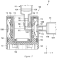
- FIG. 17 is a view of a screen changing device having a second configuration according to an embodiment.
- the method of using the apparatus 10 may include a step of shifting the first screen 130A aligned with the first connector 114 and the second connector 115 in FIG. 16 .
- the moving operation may be achieved by rotating the second housing 120 about the rotation axis A-A.
- the method may include a step of aligning the second screen 130B with the first connector 114 and the second connector 115 by rotating the second housing 120 about the rotation axis A-A.
- the pressurising operation described with reference to FIG. 16 may be performed at least once.
- a user can selectively change the plurality of screens 130A, 130B, 130C, and 130D aligned between the first connector 114 and the second connector 115 without separating the first syringe 101 and the second syringe 102 from the apparatus through the aligning step and the shifting step.
- a user can couple the first syringe 101 and the second syringe 102 to the third connector 116 and the fourth connector 117 between the aligning step and the shifting step.
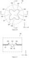
- FIG. 18 is a plan view of a screen according to an embodiment.
- FIG. 19 is an enlarged view of the part A of the screen of FIG. 18 according to an embodiment.
- a screen 230 (e.g., the first screen 130A, the second screen 130B, the third screen 130C, and/or the fourth screen 130D) may include a plate 231.
- the plate 231 may have a disc shape substantially having a circular or elliptical cross-section.
- the plate 231 may include a metal material.
- the screen 230 may include a plurality of through-holes 232 formed through the front and rear of the plate 231.
- a living tissue can be pressurised by the first plunger 101B and the second plunger 102B in the internal space of a first container (e.g., the first container 101A in FIGS. 16 and 17 ) of a first syringe and the internal space of a second container (e.g., the second container 101B in FIGS.16 and 17 ) of a second syringe.
- Pressurising the first container and the second container may be performed by other tools rather than limited to the first plunger 101B and the second plunger 102B.
- a pressurised (e.g., air pressure) living tissue can flow into the internal space of a first container (e.g., the first container 101A in FIGS. 16 and 17 ) of a first syringe and the internal space of a second container (e.g., the second container 101B in FIGS.16 and 17 ) of a second syringe through the plurality of through-holes 232 of the screen 230.
- the living tissue pressurised in the internal space of the first container and the internal space of the second container flows through the plurality of through-holes 232
- the living tissue may be pressurised by at least one edge 2321 defining the through-holes 232 having an area smaller than the cross-section of the channel P.
- the living tissue may be scratched and torn by at least one edge 2321.
- the living tissue may be sequentially and repeatedly moved into the internal space of a first container of a first syringe and the internal space of a second container of a second syringe by operation of the first plunger 101B and the second plunger 102B.
- the first plunger 101B and the second plunger 102B may be manually or electrically operated, but the present disclosure is not limited thereto.
- the plurality of through-holes 232 may include various shapes.
- the shape may include the size and/or the form of the through-holes 232.
- plurality of through-holes 232 may include a circular or elliptical shape substantially defined by one edge 2321 or may include at least one or a combination of polygonal shapes (e.g., a rectangle or a square) defined by a plurality of edges 2321.
- the plurality of through-holes 232 each may include a plurality of edges 2321 and a plurality of protrusions 2322.
- the plurality of protrusions 2322 each may protrude from one corresponding edge 2321 toward an opposite edge 2321. While the living tissue pressurised by the first plunger 101B and the second plunger 102B in the internal space of a first container and the internal space of a second container of a second syringe flows through the plurality of through-holes 232 of the screen 230, the living tissue may be pressurised by at least one edge 2321 defining the through-holes 232 having an area smaller than the cross-section of the channel P, and the protrusions 2322. The plurality of edges 2321 and protrusions 2322 may scratch and tear the living tissue.
- the screen 230 may include a plurality of holes 233.
- the plurality of holes 233 may be configured to be each fitted on one corresponding boss B shown in FIG. 12 .
- FIG. 20 is an enlarged view of the part A of the screen of FIG. 18 according to an embodiment.
- FIG. 21 is a cross-sectional view of the screen of FIG. 20 according to an embodiment taken along line 21-21.
- FIG. 22 is a cross-sectional view of the screen of FIG. 20 according to an embodiment taken along line 22-22.
- a screen 330 (e.g., the first screen 130A, the second screen 130B, the third screen 130C, and/or the fourth screen 130D, and/or the screen 230) may include a plate 331 and a plurality of through-holes 332.
- the plurality of through-holes 332 each may be defined by a plurality of edges 3321.
- the plurality of through-holes 332 each may include a plurality of edges 3321 and a plurality of protrusions 3322.
- At least one protrusion 3322 of the plurality of protrusions 3322 may protrude in a first diagonal direction (a direction between the Z axis and the Y axis) at an angle that is not 0 with respect to the plate 331. At least one protrusion 3322 of the plurality of protrusions 3322 may protrude in a second diagonal direction (a direction between the Z axis and the Y axis) that is different from the first diagonal direction at an angle that is not 0 with respect to the plate 331.
- a virtual extension line in the first diagonal direction may be in a skew position with a virtual extension line in the second diagonal direction.
- FIG. 23 is a picture of a system for reducing the size of a living tissue using a screen changing device according to an embodiment.
- a first syringe 101 is fastened to the first connector and a second syringe 115 is fastened to the second connector 115.
- a living tissue is accommodated in the first syringe 101 and the second syringe 115 is empty.
- the living tissue accommodated in the first syringe 101 passes through the first screen 130A through the first connector 114 and is then accommodated in the second syringe 102 through the second connector 115.
- the second syringe 102 is pressurised, whereby the living tissue is accommodated back into the first syringe through the first screen 130A.
- the size of the living tissue is reduced by alternately perform these processes several times.
- a process of reducing the size of the living tissue through the second screen 130B having a smaller through-hole size than the first screen is performed.
- the first connector 114 and the second connector 115 are aligned with the second screen 130B at a right position by rotating the first housing 110 with respect to the second housing 120.
- the process of reducing the size of the living tissue using the second screen is performed in the same way as the process that uses the first screen 130A.
- the sizes of the through-holes of four screens are sequentially decreased. Accordingly, the size of a living tissue is gradually reduced by sequentially selecting four screens in which the sizes of the through-holes are sequentially decreased.
- the third connector 116 and the fourth connector 117 remain as spares without being connected to a syringe.
- syringes are fastened using the third connector and the fourth connector instead of the first connector and the second connector.
Landscapes
- Health & Medical Sciences (AREA)
- Life Sciences & Earth Sciences (AREA)
- Engineering & Computer Science (AREA)
- Chemical & Material Sciences (AREA)
- Zoology (AREA)
- Organic Chemistry (AREA)
- Bioinformatics & Cheminformatics (AREA)
- Wood Science & Technology (AREA)
- Biomedical Technology (AREA)
- General Health & Medical Sciences (AREA)
- Sustainable Development (AREA)
- Microbiology (AREA)
- Biochemistry (AREA)
- General Engineering & Computer Science (AREA)
- Biotechnology (AREA)
- Genetics & Genomics (AREA)
- Molecular Biology (AREA)
- Clinical Laboratory Science (AREA)
- Heart & Thoracic Surgery (AREA)
- Animal Behavior & Ethology (AREA)
- Veterinary Medicine (AREA)
- Public Health (AREA)
- Oral & Maxillofacial Surgery (AREA)
- Epidemiology (AREA)
- Anesthesiology (AREA)
- Botany (AREA)
- Chemical Kinetics & Catalysis (AREA)
- Dermatology (AREA)
- Medicinal Chemistry (AREA)
- Vascular Medicine (AREA)
- Transplantation (AREA)
- Hematology (AREA)
- Food Science & Technology (AREA)
- Immunology (AREA)
- Apparatus Associated With Microorganisms And Enzymes (AREA)
- Measuring Or Testing Involving Enzymes Or Micro-Organisms (AREA)
- Infusion, Injection, And Reservoir Apparatuses (AREA)
- Prostheses (AREA)
- Surgical Instruments (AREA)
Applications Claiming Priority (3)
| Application Number | Priority Date | Filing Date | Title |
|---|---|---|---|
| KR20210141624 | 2021-10-22 | ||
| KR1020220134712A KR102752850B1 (ko) | 2021-10-22 | 2022-10-19 | 생체조직의 크기를 감소시키는 스크린들을 포함하는 스크린 변경 장치 |
| PCT/KR2022/016190 WO2023068883A2 (ko) | 2021-10-22 | 2022-10-21 | 스크린 변경 장치 및 이를 이용한 생체조직의 크기를 감소시키는 시스템 및 방법 |
Publications (2)
| Publication Number | Publication Date |
|---|---|
| EP4421160A2 true EP4421160A2 (de) | 2024-08-28 |
| EP4421160A4 EP4421160A4 (de) | 2025-11-19 |
Family
ID=86059535
Family Applications (1)
| Application Number | Title | Priority Date | Filing Date |
|---|---|---|---|
| EP22818176.4A Pending EP4421160A4 (de) | 2021-10-22 | 2022-10-21 | Siebwechselvorrichtung sowie system und verfahren zur reduzierung der grösse von biologischem gewebe damit |
Country Status (4)
| Country | Link |
|---|---|
| US (1) | US12595455B2 (de) |
| EP (1) | EP4421160A4 (de) |
| JP (1) | JP7587601B2 (de) |
| WO (1) | WO2023068883A2 (de) |
Family Cites Families (10)
| Publication number | Priority date | Publication date | Assignee | Title |
|---|---|---|---|---|
| US20040158226A1 (en) * | 2003-02-07 | 2004-08-12 | Genoptix, Inc. | Syringe tissue sieve |
| JP2007111653A (ja) * | 2005-10-21 | 2007-05-10 | Jsr Corp | 流路内蔵基板および流路内蔵基板の流体制御方法 |
| JP2009183149A (ja) * | 2008-02-01 | 2009-08-20 | Olympus Corp | 生体組織洗浄装置 |
| DE102013209718B4 (de) * | 2012-06-22 | 2015-09-10 | Human Med Ag | Vorrichtung zum Separieren von adulten Stammzellen |
| KR101847471B1 (ko) * | 2016-03-15 | 2018-04-11 | 가톨릭관동대학교기술지주 주식회사 | 성분 분리기, 이를 포함하는 성분 분리 키트 및 이를 이용한 성분 분리방법 |
| EP3831926A4 (de) * | 2018-08-06 | 2021-10-20 | Nissan Chemical Corporation | Zellkultursystem und verfahren zur zellmassenproduktion damit |
| KR20200119443A (ko) * | 2019-04-09 | 2020-10-20 | 이준석 | 생체조직으로부터 타겟 물질을 분리하는 방법 |
| KR102202861B1 (ko) * | 2019-04-09 | 2021-01-18 | 이준석 | 스크린 교환 장치, 이를 포함하는 생체조직 미세화 시스템, 이를 이용하는 생체조직 미세화 방법 및 이와 관련된 생체조직으로부터 타겟 물질을 분리하는 방법 |
| WO2020209609A2 (ko) * | 2019-04-09 | 2020-10-15 | 이준석 | 스크린 교환 장치, 이를 포함하는 생체조직 미세화 시스템, 이를 이용하는 생체조직 미세화 방법 및 이와 관련된 생체조직으로부터 타겟 물질을 분리하는 방법 |
| KR102632069B1 (ko) * | 2020-03-27 | 2024-02-02 | 이준석 | 기계적 방식에 의한 생체조직을 구성하는 조직 및 세포 분리 방법 |
-
2022
- 2022-10-21 US US18/013,283 patent/US12595455B2/en active Active
- 2022-10-21 EP EP22818176.4A patent/EP4421160A4/de active Pending
- 2022-10-21 JP JP2022577788A patent/JP7587601B2/ja active Active
- 2022-10-21 WO PCT/KR2022/016190 patent/WO2023068883A2/ko not_active Ceased
Also Published As
| Publication number | Publication date |
|---|---|
| US12595455B2 (en) | 2026-04-07 |
| JP7587601B2 (ja) | 2024-11-20 |
| EP4421160A4 (de) | 2025-11-19 |
| US20240034980A1 (en) | 2024-02-01 |
| WO2023068883A2 (ko) | 2023-04-27 |
| WO2023068883A3 (ko) | 2024-01-11 |
| JP2024502514A (ja) | 2024-01-22 |
Similar Documents
| Publication | Publication Date | Title |
|---|---|---|
| EP0653222B1 (de) | Selbstdichtendes flexibles Ventil aus Elastomerkunststoff und Trokar, in welchem das Ventil angeordnet ist | |
| DE60205325T2 (de) | Hydraulisches, schwingungsdämpfendes Lager mit einem verrasteten Entkopplungsventil | |
| EP1994894A1 (de) | Zugangsanordnung mit geriffelter Abdichtung | |
| EP1219250A1 (de) | Trokaranordnung mit einer Mehrzahl von Zugängen mit Obturator | |
| KR20190026586A (ko) | 생체조직 미세화 장치 | |
| US20250152789A1 (en) | Screen exchange device, biological tissue size reduction system comprising same, biological tissue size reduction method using same, and method for separating target substance from relevant biological tissue | |
| EP4421160A2 (de) | Siebwechselvorrichtung sowie system und verfahren zur reduzierung der grösse von biologischem gewebe damit | |
| CN106137340B (zh) | 一种含有凹槽结构的穿刺器密封膜 | |
| EP3718432B1 (de) | Kosmetikbehälter | |
| EP1480418B1 (de) | Verschiebbares mobiles Kommunikationsendgerät mit Scharniermechanismus | |
| Vos et al. | Intersentential syntactic context effects on comprehension: the role of working memory | |
| EP3015083B1 (de) | Dichteinrichtung zur abdichtung einer durchführung für ein medizinisches instrument | |
| JP7527907B2 (ja) | 器具用シールの2点接触フランジ | |
| KR102752850B1 (ko) | 생체조직의 크기를 감소시키는 스크린들을 포함하는 스크린 변경 장치 | |
| CN117320815A (zh) | 筛网变更装置及利用其的减小活体组织大小的系统和方法 | |
| EP3372264A1 (de) | Spritze | |
| DE602004007999T2 (de) | Drehbares Verriegelungssystem für Trokar | |
| TR2023005659T2 (tr) | Ekran deği̇şti̇rme ci̇hazi ve bunu kullanarak bi̇yoloji̇k dokunun boyutunu küçültmeye yöneli̇k si̇stem ve yöntem | |
| EP2038887A1 (de) | System und verfahren zum visuellen präsentieren von audiosignalen | |
| KR20200119443A (ko) | 생체조직으로부터 타겟 물질을 분리하는 방법 | |
| EP1760506A3 (de) | Vorrichtung zur Abdichtung von Mikroducts und/oder Mikrokabeln | |
| DE102012205545A1 (de) | Revolverbauteil für ein Reagenzgefäß, Reagenzgefäß-Einsetzteil und Reagenzgefäß | |
| JP2020099440A (ja) | コネクタ | |
| CN112137692A (zh) | 外科手术进入组件用密封组件 | |
| KR20060061312A (ko) | 다구획 화장품 용기 |
Legal Events
| Date | Code | Title | Description |
|---|---|---|---|
| STAA | Information on the status of an ep patent application or granted ep patent |
Free format text: STATUS: UNKNOWN |
|
| STAA | Information on the status of an ep patent application or granted ep patent |
Free format text: STATUS: THE INTERNATIONAL PUBLICATION HAS BEEN MADE |
|
| PUAI | Public reference made under article 153(3) epc to a published international application that has entered the european phase |
Free format text: ORIGINAL CODE: 0009012 |
|
| STAA | Information on the status of an ep patent application or granted ep patent |
Free format text: STATUS: REQUEST FOR EXAMINATION WAS MADE |
|
| 17P | Request for examination filed |
Effective date: 20221216 |
|
| AK | Designated contracting states |
Kind code of ref document: A2 Designated state(s): AL AT BE BG CH CY CZ DE DK EE ES FI FR GB GR HR HU IE IS IT LI LT LU LV MC ME MK MT NL NO PL PT RO RS SE SI SK SM TR |
|
| DAV | Request for validation of the european patent (deleted) | ||
| DAX | Request for extension of the european patent (deleted) | ||
| A4 | Supplementary search report drawn up and despatched |
Effective date: 20251021 |
|
| RIC1 | Information provided on ipc code assigned before grant |
Ipc: C12M 1/33 20060101AFI20251015BHEP Ipc: B02C 19/00 20060101ALI20251015BHEP Ipc: A61M 1/00 20060101ALI20251015BHEP Ipc: A61L 27/36 20060101ALI20251015BHEP Ipc: A61J 1/20 20060101ALI20251015BHEP Ipc: C12M 1/26 20060101ALI20251015BHEP Ipc: C12M 1/22 20060101ALI20251015BHEP Ipc: C12M 1/32 20060101ALI20251015BHEP Ipc: C12M 1/12 20060101ALI20251015BHEP Ipc: C12M 1/00 20060101ALI20251015BHEP |