EP4421155A1 - Kerze mit brennstoffversorgungsteil - Google Patents
Kerze mit brennstoffversorgungsteil Download PDFInfo
- Publication number
- EP4421155A1 EP4421155A1 EP22883873.6A EP22883873A EP4421155A1 EP 4421155 A1 EP4421155 A1 EP 4421155A1 EP 22883873 A EP22883873 A EP 22883873A EP 4421155 A1 EP4421155 A1 EP 4421155A1
- Authority
- EP
- European Patent Office
- Prior art keywords
- fuel
- fuel supply
- candle
- combustion
- storage
- Prior art date
- Legal status (The legal status is an assumption and is not a legal conclusion. Google has not performed a legal analysis and makes no representation as to the accuracy of the status listed.)
- Granted
Links
Images


Classifications
-
- C—CHEMISTRY; METALLURGY
- C11—ANIMAL OR VEGETABLE OILS, FATS, FATTY SUBSTANCES OR WAXES; FATTY ACIDS THEREFROM; DETERGENTS; CANDLES
- C11C—FATTY ACIDS FROM FATS, OILS OR WAXES; CANDLES; FATS, OILS OR FATTY ACIDS BY CHEMICAL MODIFICATION OF FATS, OILS, OR FATTY ACIDS OBTAINED THEREFROM
- C11C5/00—Candles
- C11C5/008—Candles characterised by their form; Composite candles, e.g. candles containing zones of different composition, inclusions, or the like
-
- C—CHEMISTRY; METALLURGY
- C11—ANIMAL OR VEGETABLE OILS, FATS, FATTY SUBSTANCES OR WAXES; FATTY ACIDS THEREFROM; DETERGENTS; CANDLES
- C11C—FATTY ACIDS FROM FATS, OILS OR WAXES; CANDLES; FATS, OILS OR FATTY ACIDS BY CHEMICAL MODIFICATION OF FATS, OILS, OR FATTY ACIDS OBTAINED THEREFROM
- C11C5/00—Candles
- C11C5/006—Candles wicks, related accessories
-
- F—MECHANICAL ENGINEERING; LIGHTING; HEATING; WEAPONS; BLASTING
- F23—COMBUSTION APPARATUS; COMBUSTION PROCESSES
- F23D—BURNERS
- F23D3/00—Burners using capillary action
- F23D3/02—Wick burners
- F23D3/16—Wick burners using candles
-
- F—MECHANICAL ENGINEERING; LIGHTING; HEATING; WEAPONS; BLASTING
- F23—COMBUSTION APPARATUS; COMBUSTION PROCESSES
- F23D—BURNERS
- F23D3/00—Burners using capillary action
- F23D3/02—Wick burners
- F23D3/18—Details of wick burners
- F23D3/24—Carriers for wicks
-
- F—MECHANICAL ENGINEERING; LIGHTING; HEATING; WEAPONS; BLASTING
- F23—COMBUSTION APPARATUS; COMBUSTION PROCESSES
- F23D—BURNERS
- F23D2900/00—Special features of, or arrangements for burners using fluid fuels or solid fuels suspended in a carrier gas
- F23D2900/31—Air supply for wick burners
Definitions
- the present invention relates to a candle including a fuel supply part, and more particularly, to a candle including a configuration that can continuously supply fuel to a combustion space, enhance aesthetics, and improve a scent producing effect.
- candles were used for lighting in the past and are widely used in creating certain atmospheres or in religious communities nowadays.
- Typical candles have a form in which paraffin is solidified into a solid bar shape and a wick is buried therein.
- Such candles emit heat and light due to candle wax that melts due to heat generated as the wick buried therein burns. Once used, the candles are not reusable. Dripping candle wax makes the surroundings messy and also poses a risk of fire.
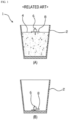
- FIG. 1A is a longitudinal cross-sectional view schematically illustrating the conventional paraffin candle
- FIG. 1B is a longitudinal cross-sectional view schematically illustrating the conventional paraffin candle that is used.
- the conventional candle includes a cup-shaped case 2, paraffin 4 filled therein, and a floating body 8 that can float in the paraffin 4 and has a wick 6 provided therein to come in contact with the paraffin 4, absorb the paraffin 4 that is melted, and burn.
- the conventional candle configured as described above begins to burn when the wick 6 is initially lighted. As the wick 6 continuously absorbs the paraffin 4 and burns, the conventional candle emits heat and light. Here, since the floating body 8 burns in the cup-shaped case 2, the floating body 8 is not much affected by external wind and stably burns, and the paraffin 4 does not drip, which keeps the surroundings clean.
- the present invention is directed to providing a candle including a configuration in which continuous fuel supply is possible due to being able to separate a space in which a fuel burns and light is generated and a space to which the fuel is supplied, aesthetics can be enhanced by easily applying various designs, and a scent producing effect can be improved.
- a candle including: a combustion part having a storage space of a predetermined volume formed therein and an open upper surface and having a fuel accommodation through-hole formed in one side surface of a lower portion; a wick support having a columnar structure that is mounted to be attachable to and detachable from a bottom surface of a center of the storage space of the combustion part and extends a predetermined height upward, having a through-hole formed in one side surface of a lower portion, having a flow tube, in which a fuel fed through the through-hole is able to flow upward due to capillary action, formed therein at a center of an inner portion to allow an upper surface and a lower surface to communicate with each other, and having a wick insertion hole formed at a center of the upper surface to allow a candle wick to be mounted and communicate with the flow tube; a storage part having a storage space of a predetermined volume formed therein and an open upper surface and having a fuel supply through-hole formed in one side surface of a
- the combustion part, the wick support, the storage part, and the fuel supply communication part may be made of a metal material that absorbs heat generated due to a flame burning the fuel while fixed due to the wick support and transfers the heat to the combustion part, the fuel supply communication part, and the fuel stored in the storage part.
- the metal material constituting the combustion part, the wick support, the storage part, and the fuel supply communication part may be a material having thermal conductivity ranging from 100 W/mK to 450 W/mK.
- the metal material constituting the combustion part, the wick support, the storage part, and the fuel supply communication part may be an alloy material mixed with one or more materials selected from the group consisting of a silver material, a copper material, a gold material, a zinc material, an aluminum material, and a tungsten material or other metal materials.
- the bottom surface of the combustion part may have a structure that comes in contact with and is parallel to a ground on which the candle will be installed
- the fuel supply communication part may be mounted to have a structure that is inclined upward at an angle ranging from 5° to 60° based on the fuel accommodation through-hole of the combustion part
- a bottom surface of the storage part may be an inclined surface that continues from the inclined structure of the fuel supply communication part.
- the storage part may include a fuel supply guide plate having a plate-shaped structure that comes in contact with an inner side surface of the storage space of the storage part and covers the open upper surface thereof, having a mesh-type structure in which a plurality of through-holes are formed, and made of a metal material that is heated by heat transferred to the storage part and transfers heat to an upper surface of the fuel stored in the storage part.
- the wick support may include: a fixing leg mounted to be attachable to and detachable from the bottom surface of the center of the storage space of the combustion part and radially extending about a central support to fix the position of the central support; and a wick end support member having a structure that radially extends from a center of an upper surface of the central support, forms a curved structure by being wound downward with a predetermined radius of curvature, and supports a portion of a side surface of an upper portion of the candle wick mounted in the wick insertion hole.
- the fixing leg of the wick support may be mounted to be attachable to and detachable from the central support, and the fixing leg of the wick support may include a height-changeable structure that is able to change a height at which the central support extends upward.
- the candle may include: a combustion part housing which is mounted to surround a side surface and a lower surface of the combustion part while opening the upper surface of the combustion part to the outside and which is filled with an insulating material or has an insulating structure formed therein; a communication part housing which is formed to surround an outer portion of the fuel supply communication part and which is filled with an insulating material or has an insulating structure formed therein; and a storage part housing which is formed to surround an outer portion of the storage part, has a structure on which an opening/closing member configured to open or close the upper surface of the storage part to or from the outside is mounted, and which is filled with an insulating material or has an insulating structure formed therein.
- the combustion part housing may include: an air intake configured to communicate with the storage space of the combustion part and supply air from the outside to the inside of the storage space of the combustion part; and an air intake amount adjustment member mounted on a side surface of the combustion part housing and configured to adjust a degree of opening of the air intake.
- the combustion part housing may include: a heat absorption part which is mounted on an upper portion of the storage space of the combustion part, mounted on an inner side surface of the open upper surface of the combustion part, has a curved structure having a center of a radius of curvature disposed at a center of an upper surface of the wick support, and is configured to absorb thermal energy generated due to a flame that burns at the upper surface of the wick support; a rotating part which is mounted to surround an outer circumferential surface of an upper portion of the wick support, has a structure having an outer diameter equal to an inner diameter of the open upper surface of the combustion part, and is configured to rotate due to air that is fed from the air intake and flows through the open upper surface of the combustion part; a forced refrigerant circulation part which has a pipe structure mounted to surround the outer circumferential surface of the upper portion of the wick support and is configured to cause a refrigerant flowing therein to flow in one direction due to the rotation of the rotating part and cause a refriger
- the candle may include: a controller mounted in the storage part housing and configured to control an operation of the air intake amount adjustment member based on data received from a light amount detection member and data input from a smart device of a user and deliver information relating to an operational state of the candle to the smart device of the user through a wireless communication module based on data detected from a fuel amount detection member; the wireless communication module mounted in the controller and configured to wirelessly interoperate with the smart device of the user, receive a control signal from the smart device of the user, transmit the control signal to the controller, and transfer data generated from the controller to the smart device of the user; the light amount detection member mounted in the combustion part housing and configured to detect a light amount of a flame burning in the combustion part in real time and then transfer detected data to the controller; and the fuel amount detection member mounted in the storage part housing and configured to detect an amount of fuel stored in the storage part in real time and then transfer detected data to the controller.
- the fuel accommodation through-hole of the combustion part may have a structure that is able to be assembled to or disassembled from the fuel supply communication part
- the fuel supply through-hole of the storage part may have a structure that is able to be assembled to or disassembled from the fuel supply communication part
- the fuel supply communication part may be bound to the fuel accommodation through-hole and the fuel supply through-hole by a structure that is able to change a slope in a vertical height direction.
- a combustion part, a wick support, a storage part, and a fuel supply communication part each having a specific structure are included, it is possible to provide a candle including a configuration in which continuous fuel supply is possible due to being able to separate a space in which a fuel burns and light is generated and a space to which the fuel is supplied.
- a combustion part, a wick support, a storage part, and a fuel supply communication part each made of a metal material having excellent thermal conductivity are included, thermal energy, which is generated in a process in which a fuel burns at an upper end of the wick support, can be effectively transferred to the fuel supply communication part and the storage part through the wick support and the combustion part, and solidification of the fuel flowing through the inside of the fuel supply communication part can be prevented using received thermal energy.
- thermal energy which is generated in a process in which a fuel burns at an upper end of the wick support
- a flow space ranging from a bottom surface of a combustion part to a bottom surface of a storage part via a fuel supply communication part is formed to have an inclined structure, a fuel stored in the storage part can naturally flow into the combustion part through a fuel supply communication part after melting due to thermal energy provided from the outside.
- a candle that can ensure continuous supply of the fuel stored in the storage part.
- a fuel supply guide plate having a specific structure since a fuel supply guide plate having a specific structure is included, thermal energy transferred to a storage part can be received and effectively transferred also to an upper surface of a fuel stored in the storage part, and a phenomenon in which only a portion of a lower end of the fuel stored in the storage part melts, causing an empty space to be formed, and a solid-phase fuel located at an upper portion of the empty space collapses inside the storage part at an unspecified point in time can be prevented.
- a candle that can ensure stable and continuous supply of the fuel stored in the storage part.
- a fixing leg, a wick end support member, and a height-changeable structure each having a specific structure are included, the position of a candle wick can be stably fixed, and thus it is possible to provide a candle that allows a fuel to be stably absorbed into the candle wick, prevents the candle wick itself from burning and shortening, and allows the height of the candle wick to be easily changed according to a user's intention.
- a combustion part housing, a communication part housing, a storage part housing, and an opening/closing member each having a specific structure are included, insulation can be performed to prevent thermal energy generated due to burning of a fuel in a combustion part from being emitted to the outside, and the thermal energy generated in the combustion part can be effectively transferred to a fuel supply communication part and a storage part, and as a result, solidification of a fuel flowing through the inside of the fuel supply communication part can be prevented using the received thermal energy.
- a candle that can ensure continuous supply of a fuel stored in the storage part.
- a candle of the present invention since various designs may be applied to outer shapes or outer surfaces of a combustion part housing, a communication part housing, a storage part housing, and an opening/closing member, various outer shapes and colors can be expressed according to an intention of a manufacturer or a user. Thus, it is possible to provide a candle of which the aesthetics can be enhanced by the manufacturer or user.
- a candle of the present invention since an air intake and an air intake amount adjustment member each having a specific structure are mounted in a combustion part housing, it is possible to provide a candle that allows an amount of fuel burning in a combustion part and a light amount of a flame generated in the combustion part to be adjusted according to a user's intention.
- a heat absorption part, a rotating part, a forced refrigerant circulation part, a heat absorption pipe part, and a heating pipe part each having a specific structure are included, thermal energy generated in a combustion part can be absorbed, and the absorbed thermal energy can be transferred to an outer circumferential surface of a fuel supply communication part, and as a result, solidification of a fuel flowing through the inside of the fuel supply communication part can be prevented using the received thermal energy.
- a candle that can ensure continuous supply of a fuel stored in a storage part.
- a controller since a controller, a wireless communication module, a light amount detection member, and a fuel amount detection member each performing a specific role are included, an amount of fuel burning in a combustion part can be easily adjusted according to a user's intention, a light amount of a flame generated due to burning in the combustion part can be easily adjusted, and the amount of fuel stored in a storage part can be checked in real time.
- a controller since a controller, a wireless communication module, a light amount detection member, and a fuel amount detection member each performing a specific role are included, an amount of fuel burning in a combustion part can be easily adjusted according to a user's intention, a light amount of a flame generated due to burning in the combustion part can be easily adjusted, and the amount of fuel stored in a storage part can be checked in real time.
- a candle that allows a time to refill the fuel to be conveniently checked.
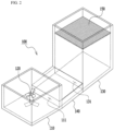
- FIG. 2 is a perspective view illustrating a candle according to one embodiment of the present invention.
- a candle 100 has a combustion part 110, a wick support 120, a storage part 130, and a fuel supply communication part 140 each having a specific structure, and thus it is possible to provide a candle including a configuration in which continuous fuel supply is possible due to being able to separate a space in which a fuel burns and light is generated and a space to which the fuel is supplied.
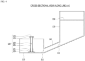
- FIG. 3 is a plan view of the candle illustrated in FIG. 2
- FIG. 4 is a cross-sectional view along line A-A' of FIG. 3 .
- the combustion part 110 is a structure having a storage space of a predetermined volume formed therein, an open upper surface, and a fuel accommodation through-hole 111 formed in one side surface of a lower portion.
- the wick support 120 is a columnar structure that is mounted to be attachable to and detachable from a bottom surface of a center of the storage space of the combustion part 110 and extends a predetermined height upward.
- a through-hole 121 is formed in one side surface of a lower portion, and a flow tube 122, in which a fuel fed through the through-hole 121 is able to flow upward due to capillary action, is formed therein at a center of an inner portion to allow an upper surface and a lower surface to communicate with each other.
- a wick insertion hole 123 is formed at a center of the upper surface to allow a candle wick 120a to be mounted and communicate with the flow tube 122.
- the wick support 120 may be a component that includes a fixing leg 124 and a wick end support member 125 each having a specific structure.
- the fixing leg 124 of the wick support 120 is a component mounted to be attachable to and detachable from the bottom surface of the center of the storage space of the combustion part 110 and may radially extend about a central support 126 to fix the position of the central support 126.
- the wick end support member 125 is a component that radially extends from a center of an upper surface of the central support 126 and forms a curved structure by being wound downward with a predetermined radius of curvature, and is a structure that supports a portion of a side surface of an upper portion of the candle wick 120a mounted in the wick insertion hole 123.
- the fixing leg 124 of the wick support 120 may be mounted to be attachable to and detachable from the central support 126.
- the fixing leg 124 of the wick support 120 may include a height-changeable structure (not illustrated) that is able to change a height at which the central support 126 extends upward.
- the fixing leg 124, the wick end support member 125, and the height-changeable structure each having a specific structure are included, the position of the candle wick 120a can be stably fixed, and thus it is possible to provide a candle that allows a fuel to be stably absorbed into the candle wick 120a, prevents the candle wick 120a itself from burning and shortening, and allows the height of the candle wick 120a to be easily changed according to a user's intention.
- the storage part 130 is a structure having a storage space of a predetermined volume formed therein, an open upper surface, and a fuel supply through-hole 131 formed in one side surface of a lower portion.
- the storage part 130 may be a component that further includes a fuel supply guide plate 150 having a specific structure.
- the fuel supply guide plate 150 may have a plate-shaped structure that comes in contact with an inner side surface of the storage space of the storage part 130 and covers the open upper surface thereof, may have a mesh-type structure in which a plurality of through-holes are formed, and may be made of a metal material that is heated by heat transferred to the storage part 130 and transfers heat to an upper surface of the fuel stored in the storage part 130.
- the fuel supply guide plate 150 having a specific structure since the fuel supply guide plate 150 having a specific structure is included, thermal energy transferred to the storage part 130 can be received and effectively transferred also to the upper surface of the fuel stored in the storage part 130, and a phenomenon in which only a portion of a lower end of the fuel stored in the storage part 130 melts, causing an empty space to be formed, and a solid-phase fuel located at an upper portion of the empty space collapses inside the storage part 130 at an unspecified point in time can be prevented.
- a candle that can ensure stable and continuous supply of the fuel stored in the storage part 130.
- the fuel supply communication part 140 is a component that is mounted to allow communication between the fuel accommodation through-hole 111 of the combustion part 110 and the fuel supply through-hole 131 of the storage part 130.
- the combustion part 110, the wick support 120, the storage part 130, and the fuel supply communication part 140 may be made of a metal material that absorbs heat generated due to a flame burning the fuel while fixed due to the wick support 120 and transfers the heat to the combustion part 110, the fuel supply communication part 140, and the fuel stored in the storage part 130.
- the metal material constituting the combustion part 110, the wick support 120, the storage part 130, and the fuel supply communication part 140 may be a material having thermal conductivity ranging from 100 W/mK to 450 W/mK.
- the metal material constituting the combustion part 110, the wick support 120, the storage part 130, and the fuel supply communication part 140 may be an alloy material mixed with one or more materials selected from the group consisting of a silver material, a copper material, a gold material, a zinc material, an aluminum material, and a tungsten material or other metal materials.
- the combustion part 110, the wick support 120, the storage part 130, and the fuel supply communication part 140 each made of a metal material having excellent thermal conductivity are included, thermal energy, which is generated in a process in which a fuel burns at an upper end of the wick support 120, can be effectively transferred to the fuel supply communication part 140 and the storage part 130 through the wick support 120 and the combustion part 110, and solidification of the fuel flowing through the inside of the fuel supply communication part 140 can be prevented using received thermal energy.
- thermal energy which is generated in a process in which a fuel burns at an upper end of the wick support 120, can be effectively transferred to the fuel supply communication part 140 and the storage part 130 through the wick support 120 and the combustion part 110, and solidification of the fuel flowing through the inside of the fuel supply communication part 140 can be prevented using received thermal energy.
- the bottom surface of the combustion part 110 may have a structure that comes in contact with and is parallel to the ground on which the candle 100 will be installed, and the fuel supply communication part 140 may be mounted to have a structure that is inclined upward at an angle ranging from 5° to 60° based on the fuel accommodation through-hole 111 of the combustion part 110.
- a bottom surface of the storage part 130 may be an inclined surface that continues from the inclined structure of the fuel supply communication part 140.
- a flow space ranging from the bottom surface of the combustion part 110 to the bottom surface of the storage part 130 via the fuel supply communication part 140 is formed to have an inclined structure, a fuel stored in the storage part 130 can naturally flow into the combustion part 110 through the fuel supply communication part 140 after melting due to thermal energy provided from the outside.
- a candle that can ensure continuous supply of the fuel stored in the storage part 130.
- the fuel accommodation through-hole 111 of the combustion part 110 may have a structure that is able to be assembled to or disassembled from the fuel supply communication part 140
- the fuel supply through-hole 131 of the storage part 130 may have a structure that is able to be assembled to or disassembled from the fuel supply communication part 140
- the fuel supply communication part 140 may be bound to the fuel accommodation through-hole 111 and the fuel supply through-hole 131 by a structure that is able to change a slope in a vertical height direction.
- FIG. 5 is a longitudinal cross-sectional view illustrating a candle according to another embodiment of the present invention.
- a candle 100 may be a component that includes a combustion part housing 161, a communication part housing 162, and a storage part housing 163 each having a specific structure.
- the combustion part housing 161 is mounted to surround a side surface and a lower surface of the combustion part 110 while opening the upper surface of the combustion part 110 to the outside and is a structure which is filled with an insulating material or has an insulating structure formed therein.
- the communication part housing 162 is formed to surround an outer portion of the fuel supply communication part 140 and is a structure which is filled with an insulating material or has an insulating structure formed therein.
- the storage part housing 163 is formed to surround an outer portion of the storage part 130, has a structure on which an opening/closing member 164 configured to open or close the upper surface of the storage part 130 to or from the outside is mounted, and is a structure which is filled with an insulating material or has an insulating structure formed therein.
- the combustion part housing 161, the communication part housing 162, the storage part housing 163, and the opening/closing member 164 each having a specific structure are included, insulation can be performed to prevent thermal energy generated due to burning of a fuel in the combustion part 110 from being emitted to the outside, and the thermal energy generated in the combustion part 110 can be effectively transferred to the fuel supply communication part 140 and the storage part 130, and as a result, solidification of a fuel flowing through the inside of the fuel supply communication part 140 can be prevented using the received thermal energy.
- FIG. 6 is a longitudinal cross-sectional view illustrating a candle according to still another embodiment of the present invention.
- the combustion part housing 161 may be a component that further includes an air intake 165 and an air intake amount adjustment member 166.
- the air intake 165 of the combustion part housing 161 is a component configured to communicate with the storage space of the combustion part 110 and is a structure configured to supply air from the outside to the inside of the storage space of the combustion part 110.
- the air intake amount adjustment member 166 is a component mounted on a side surface of the combustion part housing 161 and is a structure configured to adjust a degree of opening of the air intake 165.
- the air intake 165 and the air intake amount adjustment member 166 each having a specific structure are mounted in the combustion part housing 161, it is possible to provide a candle that allows an amount of fuel burning in the combustion part 110 and a light amount of a flame generated in the combustion part 110 to be adjusted according to a user's intention.
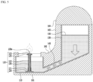
- FIG. 7 is a longitudinal cross-sectional view illustrating a candle according to yet another embodiment of the present invention
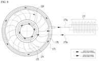
- FIG. 8 is a plan view schematically illustrating a heat absorption part, a rotating part, a forced refrigerant circulation part, a heat absorption pipe part, and a heating pipe part of FIG. 7 .
- a candle 100 may be a component that includes a heat absorption part 173, a rotating part 174, a forced refrigerant circulation part 175, a heat absorption pipe part 176, and a heating pipe part 177 each having a specific structure.
- the heat absorption part 173 is a component which is mounted on an upper portion of the storage space of the combustion part 110 and mounted on an inner side surface of the open upper surface of the combustion part 110 and may have a curved structure having a center of a radius of curvature disposed at a center of an upper surface of the wick support 120 and absorb thermal energy generated due to a flame that burns at the upper surface of the wick support 120.
- the rotating part 174 is a component which is mounted to surround an outer circumferential surface of the upper portion of the wick support 120, has a structure having an outer diameter equal to an inner diameter of the open upper surface of the combustion part 110, and may rotate due to air that is fed from the air intake 165 and flows through the open upper surface of the combustion part 110.
- the forced refrigerant circulation part 175 is a pipe structure mounted to surround the outer circumferential surface of the upper portion of the wick support 120 and may cause a refrigerant flowing therein to flow in one direction due to the rotation of the rotating part 174 and cause a refrigerant received from the heating pipe part 177 to flow to the heat absorption pipe part 176.
- the heat absorption pipe part 176 is a component which is mounted in the heat absorption part 173 and may extend in a direction identical to a direction in which the heat absorption part 173 extends, transfer thermal energy absorbed from the heat absorption part 173 to a refrigerant flowing therein, and cause the refrigerant received from the forced refrigerant circulation part 175 to flow to the heating pipe part 177.
- the heating pipe part 177 is a component which is mounted to surround an outer circumferential surface of the fuel supply communication part 140, is a pipe structure configured to cause a heated refrigerant received from the heating pipe part 177 to flow, and may transfer thermal energy of the heated refrigerant to the fuel supply communication part 140 and cause the refrigerant received from the heat absorption pipe part 176 to flow to the heat absorption pipe part 176.
- the heat absorption part 173, the rotating part 174, the forced refrigerant circulation part 175, the heat absorption pipe part 176, and the heating pipe part 177 each having a specific structure are included, thermal energy generated in the combustion part 110 can be absorbed, and the absorbed thermal energy can be transferred to the outer circumferential surface of the fuel supply communication part 140, and as a result, solidification of a fuel flowing through the inside of the fuel supply communication part 140 can be prevented using the received thermal energy.
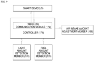
- FIG. 9 is a control block diagram of a candle according to yet another embodiment of the present invention.
- a candle 100 may be a component that includes a controller 171, a wireless communication module 172, a light amount detection member 178, and a fuel amount detection member 179.
- the controller 171 is a component mounted in the storage part housing 163 and may control an operation of the air intake amount adjustment member 166 based on data received from the light amount detection member 178 and data input from a smart device of a user and deliver information relating to an operational state of the candle to the smart device of the user through the wireless communication module 172 based on data detected from the fuel amount detection member.
- the wireless communication module 172 is a component mounted in the controller 171 and may wirelessly interoperate with the smart device of the user, receive a control signal from the smart device of the user, transmit the control signal to the controller 171, and transfer data generated from the controller 171 to the smart device of the user.
- the light amount detection member 178 is a component mounted in the combustion part housing 161 and may detect a light amount of a flame burning in the combustion part 110 in real time and then transfer detected data to the controller 171.
- the fuel amount detection member 179 is a component mounted in the storage part housing 163 and may detect an amount of fuel stored in the storage part 130 in real time and then transfer detected data to the controller 171.
- an amount of fuel burning in the combustion part 110 can be easily adjusted according to a user's intention, a light amount of a flame generated due to burning in the combustion part 110 can be easily adjusted, and the amount of fuel stored in the storage part 130 can be checked in real time.
- a candle that allows a time to refill the fuel to be conveniently checked.
- an aromatic may be mounted on an upper portion of the storage part 130 to improve a scent producing effect.
- an aromatic may be mounted on an upper surface of the fuel supply guide plate 150 disposed in the storage part 130.
- the aromatic that may be mounted include a scented plaster, a scented gel, and the like.
- the scent producing effect of the aromatic disposed at the upper portion of the storage part 130 may be improved by thermal energy transferred to the storage part 130.
- a plurality of through-holes may be formed in the opening/closing member 164 for a scent to spread to the outside.
- the present invention relates to a candle including a fuel supply part and can provide a candle including a fuel supply part that can continuously supply a fuel to a combustion space, enhance aesthetics, and improve a scent producing effect.
- the present invention has industrial applicability.
Landscapes
- Chemical & Material Sciences (AREA)
- Engineering & Computer Science (AREA)
- General Chemical & Material Sciences (AREA)
- Life Sciences & Earth Sciences (AREA)
- Chemical Kinetics & Catalysis (AREA)
- Oil, Petroleum & Natural Gas (AREA)
- Wood Science & Technology (AREA)
- Organic Chemistry (AREA)
- Composite Materials (AREA)
- Combustion & Propulsion (AREA)
- General Engineering & Computer Science (AREA)
- Mechanical Engineering (AREA)
- Arrangement Of Elements, Cooling, Sealing, Or The Like Of Lighting Devices (AREA)
- Fats And Perfumes (AREA)
- Feeding And Controlling Fuel (AREA)
- Non-Portable Lighting Devices Or Systems Thereof (AREA)
Applications Claiming Priority (2)
| Application Number | Priority Date | Filing Date | Title |
|---|---|---|---|
| KR1020210140481A KR102354486B1 (ko) | 2021-10-20 | 2021-10-20 | 연료공급부를 포함하는 캔들 |
| PCT/KR2022/015481 WO2023068650A1 (ko) | 2021-10-20 | 2022-10-13 | 연료공급부를 포함하는 캔들 |
Publications (4)
| Publication Number | Publication Date |
|---|---|
| EP4421155A1 true EP4421155A1 (de) | 2024-08-28 |
| EP4421155A4 EP4421155A4 (de) | 2025-04-23 |
| EP4421155B1 EP4421155B1 (de) | 2025-12-17 |
| EP4421155C0 EP4421155C0 (de) | 2025-12-17 |
Family
ID=80050461
Family Applications (1)
| Application Number | Title | Priority Date | Filing Date |
|---|---|---|---|
| EP22883873.6A Active EP4421155B1 (de) | 2021-10-20 | 2022-10-13 | Kerze mit brennstoffversorgungsteil |
Country Status (6)
| Country | Link |
|---|---|
| US (1) | US12258538B2 (de) |
| EP (1) | EP4421155B1 (de) |
| JP (1) | JP7742675B2 (de) |
| KR (1) | KR102354486B1 (de) |
| CN (1) | CN118202026B (de) |
| WO (1) | WO2023068650A1 (de) |
Families Citing this family (1)
| Publication number | Priority date | Publication date | Assignee | Title |
|---|---|---|---|---|
| KR102354486B1 (ko) * | 2021-10-20 | 2022-01-21 | 안상권 | 연료공급부를 포함하는 캔들 |
Family Cites Families (16)
| Publication number | Priority date | Publication date | Assignee | Title |
|---|---|---|---|---|
| DE2929912A1 (de) * | 1979-07-24 | 1981-02-19 | Schirnecker Hans Ludwig | Feuerschale |
| US5405262A (en) * | 1994-06-07 | 1995-04-11 | Appel; Ron I. | Adjustable burning canned heating apparatus |
| ATE176721T1 (de) * | 1994-07-16 | 1999-02-15 | Schirnecker Hans Ludwig | Leuchte, insbesondere paraffinleuchte |
| KR200210010Y1 (ko) * | 2000-08-18 | 2001-01-15 | 김유리 | 양초 |
| TW439944U (en) * | 2000-09-29 | 2001-06-07 | Lamp Light Internat Entpr Co L | Lamp stand device capable of automatically replenishing lamp oil |
| US6508644B1 (en) * | 2001-08-17 | 2003-01-21 | Bath & Body Works, Inc. | Flame-resistant wick holder for candle |
| KR200452808Y1 (ko) | 2009-05-26 | 2011-03-25 | 이철헌 | 파라핀 양초 |
| KR20110016029A (ko) | 2009-08-10 | 2011-02-17 | 정재은 | 촛대 겸용 양초 |
| KR20110017075A (ko) | 2009-08-13 | 2011-02-21 | 이관훈 | 파라핀 오일을 이용한 양초 |
| US8573967B2 (en) * | 2010-10-01 | 2013-11-05 | S.C. Johnson & Son, Inc. | Candle assembly and fuel element therefor |
| KR101835103B1 (ko) | 2016-07-08 | 2018-03-08 | 전호성 | 부양캔들 |
| KR20180098427A (ko) * | 2017-02-24 | 2018-09-04 | 이진철 | 캔들용 유동심지 및 유동심지를 이용한 유동캔들 |
| US10378754B1 (en) * | 2018-04-13 | 2019-08-13 | Jamie Durrence | Systems and methods for refilling liquid fuel candles |
| KR200495893Y1 (ko) | 2019-12-16 | 2022-09-15 | 장재영 | 멀티심지를 갖는 캔들 어셈블리 |
| KR102269188B1 (ko) * | 2020-12-28 | 2021-06-24 | 김성환 | 케이스형 양초용 촛대 |
| KR102354486B1 (ko) * | 2021-10-20 | 2022-01-21 | 안상권 | 연료공급부를 포함하는 캔들 |
-
2021
- 2021-10-20 KR KR1020210140481A patent/KR102354486B1/ko active Active
-
2022
- 2022-10-13 EP EP22883873.6A patent/EP4421155B1/de active Active
- 2022-10-13 US US18/703,225 patent/US12258538B2/en active Active
- 2022-10-13 WO PCT/KR2022/015481 patent/WO2023068650A1/ko not_active Ceased
- 2022-10-13 JP JP2024524994A patent/JP7742675B2/ja active Active
- 2022-10-13 CN CN202280069870.7A patent/CN118202026B/zh active Active
Also Published As
| Publication number | Publication date |
|---|---|
| KR102354486B1 (ko) | 2022-01-21 |
| EP4421155B1 (de) | 2025-12-17 |
| JP2024538249A (ja) | 2024-10-18 |
| EP4421155C0 (de) | 2025-12-17 |
| CN118202026B (zh) | 2024-12-13 |
| WO2023068650A1 (ko) | 2023-04-27 |
| EP4421155A4 (de) | 2025-04-23 |
| CN118202026A (zh) | 2024-06-14 |
| JP7742675B2 (ja) | 2025-09-22 |
| US12258538B2 (en) | 2025-03-25 |
| US20240336872A1 (en) | 2024-10-10 |
Similar Documents
| Publication | Publication Date | Title |
|---|---|---|
| US6802707B2 (en) | Melting plate candles | |
| US7850444B2 (en) | Fuel element for melting plate candle assembly | |
| WO1999023416A1 (en) | Low-burning candle | |
| CA2617956C (en) | Candle assembly including a fuel element and a wick holder | |
| ES2329083T3 (es) | Montaje portador de mecha. | |
| US9890950B2 (en) | Fuel burning system and method | |
| US20200049344A1 (en) | Solid Fuel Burning System and Method with Electronic Ignition | |
| EP1564485A2 (de) | Kerzen mit Schmelzplatte | |
| US20060084021A1 (en) | Wick holder | |
| MXPA01005339A (es) | Soporte de pabilo anti flamazo. | |
| US10519399B2 (en) | Candle with scent | |
| EP4421155A1 (de) | Kerze mit brennstoffversorgungsteil | |
| US20180335206A1 (en) | Wax Burning System | |
| JP6556729B2 (ja) | 液体キャンドルシステム | |
| US20080227043A1 (en) | Disposable, floating, flame heated wax melting plate for confined and unconfined conventional candles and attachment method for use in candle making | |
| US7252805B2 (en) | Device for vaporising and diffusing oils | |
| US6333009B1 (en) | Heating element for oil burning lamp | |
| US6426051B1 (en) | Oil burning lamp adapted to disperse fragrance | |
| KR102750433B1 (ko) | 향이 멀리퍼질 수 있도록 형성된 디퓨저 | |
| RU2196813C2 (ru) | Свеча многоразовая | |
| KR200182528Y1 (ko) | 심지 지지대가 형성된 초 | |
| KR200210829Y1 (ko) | 양초 비바람막이 기구 | |
| KR20130090723A (ko) | 불꽃 위치가 유지되며 불꽃크기를 정할 수 있는 심지 교체가 가능한 양초 | |
| CZ11058U1 (cs) | Dekorativní svítidlo s ekonomickým provozem |
Legal Events
| Date | Code | Title | Description |
|---|---|---|---|
| STAA | Information on the status of an ep patent application or granted ep patent |
Free format text: STATUS: THE INTERNATIONAL PUBLICATION HAS BEEN MADE |
|
| PUAI | Public reference made under article 153(3) epc to a published international application that has entered the european phase |
Free format text: ORIGINAL CODE: 0009012 |
|
| STAA | Information on the status of an ep patent application or granted ep patent |
Free format text: STATUS: REQUEST FOR EXAMINATION WAS MADE |
|
| 17P | Request for examination filed |
Effective date: 20240418 |
|
| AK | Designated contracting states |
Kind code of ref document: A1 Designated state(s): AL AT BE BG CH CY CZ DE DK EE ES FI FR GB GR HR HU IE IS IT LI LT LU LV MC ME MK MT NL NO PL PT RO RS SE SI SK SM TR |
|
| DAV | Request for validation of the european patent (deleted) | ||
| DAX | Request for extension of the european patent (deleted) | ||
| A4 | Supplementary search report drawn up and despatched |
Effective date: 20250325 |
|
| RIC1 | Information provided on ipc code assigned before grant |
Ipc: F23D 3/24 20060101ALI20250319BHEP Ipc: F23D 3/16 20060101ALI20250319BHEP Ipc: C11C 5/00 20060101AFI20250319BHEP |
|
| GRAP | Despatch of communication of intention to grant a patent |
Free format text: ORIGINAL CODE: EPIDOSNIGR1 |
|
| STAA | Information on the status of an ep patent application or granted ep patent |
Free format text: STATUS: GRANT OF PATENT IS INTENDED |
|
| RIC1 | Information provided on ipc code assigned before grant |
Ipc: C11C 5/00 20060101AFI20250630BHEP Ipc: F23D 3/16 20060101ALI20250630BHEP Ipc: F23D 3/24 20060101ALI20250630BHEP |
|
| INTG | Intention to grant announced |
Effective date: 20250711 |
|
| GRAS | Grant fee paid |
Free format text: ORIGINAL CODE: EPIDOSNIGR3 |
|
| GRAA | (expected) grant |
Free format text: ORIGINAL CODE: 0009210 |
|
| STAA | Information on the status of an ep patent application or granted ep patent |
Free format text: STATUS: THE PATENT HAS BEEN GRANTED |
|
| AK | Designated contracting states |
Kind code of ref document: B1 Designated state(s): AL AT BE BG CH CY CZ DE DK EE ES FI FR GB GR HR HU IE IS IT LI LT LU LV MC ME MK MT NL NO PL PT RO RS SE SI SK SM TR |
|
| REG | Reference to a national code |
Ref country code: CH Ref legal event code: F10 Free format text: ST27 STATUS EVENT CODE: U-0-0-F10-F00 (AS PROVIDED BY THE NATIONAL OFFICE) Effective date: 20251217 Ref country code: GB Ref legal event code: FG4D |
|
| REG | Reference to a national code |
Ref country code: DE Ref legal event code: R096 Ref document number: 602022027211 Country of ref document: DE |
|
| U01 | Request for unitary effect filed |
Effective date: 20260116 |
|
| U07 | Unitary effect registered |
Designated state(s): AT BE BG DE DK EE FI FR IT LT LU LV MT NL PT RO SE SI Effective date: 20260122 |
|
| PG25 | Lapsed in a contracting state [announced via postgrant information from national office to epo] |
Ref country code: NO Free format text: LAPSE BECAUSE OF FAILURE TO SUBMIT A TRANSLATION OF THE DESCRIPTION OR TO PAY THE FEE WITHIN THE PRESCRIBED TIME-LIMIT Effective date: 20260317 |
|
| PG25 | Lapsed in a contracting state [announced via postgrant information from national office to epo] |
Ref country code: HR Free format text: LAPSE BECAUSE OF FAILURE TO SUBMIT A TRANSLATION OF THE DESCRIPTION OR TO PAY THE FEE WITHIN THE PRESCRIBED TIME-LIMIT Effective date: 20251217 |
|
| PG25 | Lapsed in a contracting state [announced via postgrant information from national office to epo] |
Ref country code: RS Free format text: LAPSE BECAUSE OF FAILURE TO SUBMIT A TRANSLATION OF THE DESCRIPTION OR TO PAY THE FEE WITHIN THE PRESCRIBED TIME-LIMIT Effective date: 20260317 |