EP4420506A1 - Erntemaschine - Google Patents
Erntemaschine Download PDFInfo
- Publication number
- EP4420506A1 EP4420506A1 EP23216552.2A EP23216552A EP4420506A1 EP 4420506 A1 EP4420506 A1 EP 4420506A1 EP 23216552 A EP23216552 A EP 23216552A EP 4420506 A1 EP4420506 A1 EP 4420506A1
- Authority
- EP
- European Patent Office
- Prior art keywords
- conveyor screw
- crop
- mass flow
- tank
- drive unit
- Prior art date
- Legal status (The legal status is an assumption and is not a legal conclusion. Google has not performed a legal analysis and makes no representation as to the accuracy of the status listed.)
- Granted
Links
Images


Classifications
-
- A—HUMAN NECESSITIES
- A01—AGRICULTURE; FORESTRY; ANIMAL HUSBANDRY; HUNTING; TRAPPING; FISHING
- A01F—PROCESSING OF HARVESTED PRODUCE; HAY OR STRAW PRESSES; DEVICES FOR STORING AGRICULTURAL OR HORTICULTURAL PRODUCE
- A01F12/00—Parts or details of threshing apparatus
- A01F12/46—Mechanical grain conveyors
-
- A—HUMAN NECESSITIES
- A01—AGRICULTURE; FORESTRY; ANIMAL HUSBANDRY; HUNTING; TRAPPING; FISHING
- A01D—HARVESTING; MOWING
- A01D41/00—Combines, i.e. harvesters or mowers combined with threshing devices
- A01D41/12—Details of combines
- A01D41/1208—Tanks for grain or chaff
-
- A—HUMAN NECESSITIES
- A01—AGRICULTURE; FORESTRY; ANIMAL HUSBANDRY; HUNTING; TRAPPING; FISHING
- A01D—HARVESTING; MOWING
- A01D41/00—Combines, i.e. harvesters or mowers combined with threshing devices
- A01D41/12—Details of combines
- A01D41/127—Control or measuring arrangements specially adapted for combines
- A01D41/1271—Control or measuring arrangements specially adapted for combines for measuring crop flow
- A01D41/1272—Control or measuring arrangements specially adapted for combines for measuring crop flow for measuring grain flow
Definitions
- the present invention relates to a harvesting machine such as a combine harvester, in particular the filling of a crop tank of the harvesting machine, as well as a conveyor screw designed therefor.
- the grain As the grain separates from non-grain components of the crop during threshing, it must then be transported upwards to fill the combine harvester's crop tank. This is often done using an elevator with blades rotating on a chain that pick up grain collected at the bottom of the threshing unit, lift it up and discharge it into the crop tank via a grain inlet opening in one wall of the crop tank. In this way, the crop tank cannot be filled higher than the bottom edge of the grain inlet opening.
- a first conveyor screw is proposed which is pivotably mounted inside the grain tank at the grain inlet opening, picks up grain delivered by the elevator and lifts it further.
- a second conveyor screw is connected to the first conveyor screw. The second conveyor screw is arranged vertically in the crop tank and conveys the crop delivered by the first conveyor screw further vertically upwards.
- the conveying capacity of the first and second screw conveyors is usually designed for the maximum possible throughput. However, this throughput is only achieved for a small proportion of the annual operating spectrum. Many machines do not achieve these throughputs at all due to their operating conditions.
- a harvesting machine comprising a crop tank with a first conveyor screw inside the tank, which extends from a crop inlet opening on a wall of the crop tank into the interior of the crop tank, a second conveyor screw inside the tank, wherein the second conveyor screw is in conveying connection with the first conveyor screw, a drive unit, wherein the drive unit is drivingly connected to the second conveyor screw, a mass flow sensor for determining a mass flow, a control device for controlling the drive unit, wherein the control device is set up such that it controls a rotational speed of the drive unit depending on the mass flow determined by means of the mass flow sensor.
- the invention has many advantages.
- the conveying capacity of the second auger is adapted to the throughput of the harvesting machine. This is particularly advantageous because harvesting machines rarely reach the maximum throughput in their annual range of use, so that adjusting the speed to the current throughput leads to a reduction in the drive power required to drive the second auger and significantly reduces signs of wear on the second auger.
- Controlling the speed of the second auger as a function of the mass flow sensor means that the conveying capacity of the second auger essentially corresponds to the conveying capacity of the first auger. Reactive power occurring on the second auger is avoided.
- the mass flow is understood to be the amount of crop that is conveyed by a working unit of the harvesting machine.
- the working unit is particularly preferably the grain elevator. If a low mass flow is identified using the mass flow sensor, a lower speed is preferably set on the drive unit than if a larger mass flow is identified.
- the drive unit can be arranged directly on the second conveyor screw, wherein preferably the first conveyor screw is separate from the second auger conveyor is driven.
- the arrangement of the drive unit directly on the second auger conveyor, whereby the drive unit is directly coupled to the shaft of the second auger conveyor, enables the speed of the second auger conveyor to be set independently of the first auger conveyor.
- the speed of the second auger conveyor can therefore be optimally adapted to the current harvesting situation and the amount of crop in the crop tank.
- the separate drive of the second auger conveyor is particularly advantageous, as it can thus be pivoted independently of the first auger conveyor from a vertically aligned working position to a flatter parking position.
- the drive unit can be designed as a hydraulic motor.
- a further advantageous embodiment provides that the control device regulates the speed of the drive unit in such a way that the speed of the second conveyor screw has a constant minimum speed until a quantity of crop fed to the crop tank reaches a defined fill level and after the defined fill level is exceeded, the speed of the second conveyor screw is regulated depending on the mass flow sensor.
- the second conveyor screw is intended and set up to continue filling the crop beyond a fill level that can be reached by means of the first conveyor screw. Accordingly, the need to convey the crop is only necessary from a certain fill level within the crop tank. Nevertheless, it is particularly advantageous not to leave the second conveyor screw at a standstill until the fill level is reached, but to operate it at a minimum speed.
- Crop guided by the first conveyor screw in the direction of the second conveyor screw is redirected by the screw turns of the second conveyor screw. If the second auger is in an unfavourable position, the crop can be continuously directed against a grain tank window.
- the grain tank window gives a person inside the vehicle cab a view into the grain tank, but crop diverted against the grain tank window can create annoying noises in the driver's cab. Operating the second auger at the minimum speed prevents crop from being continuously directed against the driver's cab.
- the defined fill level corresponds to a height of the lower end of the second conveyor screw. Only when this fill level is reached does the second conveyor screw effectively convey crops in the crop tank in a vertical direction.
- the first conveyor screw In order to be able to safely take over crops from a grain elevator and to convey them with minimal loss, the first conveyor screw should be surrounded by a pipe, whereby the pipe has an opening that allows crops to exit into the crop tank. Because the first conveyor screw is surrounded by a pipe, the mass flow determined by the mass flow sensor is also essentially fed to the second conveyor screw, so that the speed of the second conveyor screw can be optimally adapted to the mass flow fed to it.
- the second conveyor screw is not piped. This means that the second conveyor screw is not surrounded by a pipe along its length.
- Such unpiped second conveyor screws are often used in harvesting machines inside the crop tank.
- the mass flow-dependent speed control is particularly advantageous for such unpiped second conveyor screws, especially since from the defined fill level the second conveyor screw is at least partially surrounded by crop, so that crop already in the crop tank can reach the envelope of the second conveyor screw and be conveyed by it again in a vertical direction. It is therefore possible for crop to be conveyed in a circle.
- the second conveyor screw is, however, intended to accept the crop conveyed by the first conveyor screw and to convey it out of the discharge area of the first conveyor screw in order to relieve the load on it.
- the mass flow-dependent control now means that when the first conveyor screw delivers a low delivery rate, a low speed is set on the second conveyor screw. Additional, so-called digging work, whereby crops already inside the crop tank slip into the envelope of the second auger, is at least reduced.
- the harvesting machine can comprise a conveying device, in particular a grain elevator, which is provided and set up to convey the mass flow consisting of crop material from a lower crop receiving area to a higher crop delivery area, wherein the mass flow sensor is assigned to determine the mass flow of the conveying device.
- a grain elevator is arranged upstream of the first conveyor screw. The crop material conveyed by the grain elevator is fed to the first conveyor screw without loss and is conveyed from there to the receiving area of the second conveyor screw.
- An arrangement of the mass flow sensor within the grain elevator is therefore particularly suitable for determining the mass flow that is fed to the second conveyor screw.
- Fig.1 shows a schematic longitudinal section through a harvesting machine 1 designed as a combine harvester with a foldable extension device 2 for increasing the volume of a crop tank 3.
- the combine harvester is equipped with a cutting unit 4 on the front, which is arranged on an inclined conveyor 5.
- the combine harvester uses the cutting unit 4 to pick up the crop 6 and feeds it to the inclined conveyor 5.
- the inclined conveyor 5 transfers the crop 6 to a downstream threshing unit 7.
- the threshing unit 7 prepares the crop 6, dividing it into a grain-chaff mixture 8 and a crop stream 9 consisting of threshed stalks.
- the grain-chaff mixture 8 is conveyed via a preparation floor 10 directly to a cleaning device 11, which separates the grain 12 from the non-grain components 13, i.e. from stalk and chaff parts.
- a turning drum 14 is arranged that rotates in an anti-clockwise direction and conveys the crop stream 9 consisting of threshed stalks to a tray shaker 15.
- the tray shaker 15 separates the grain 12, short straw 16 and chaff 17 still present in the crop stream 9, which also reach the cleaning device 11 via a return floor 18.
- the grains 12 separated by the cleaning device 11 are conveyed by a conveyor device 52 designed as a grain elevator 19 into the crop tank 3.
- the grain elevator 19 comprises an endlessly rotating conveyor chain 23 equipped with shovels 22.
- the shovels 22 take the grain 12 from the cleaning device 11 and convey it upwards in a shaft to a material inlet opening 24 in a wall 25 of the crop tank 3.
- the crop tank 3 is designed as a container with a substantially rectangular base and is arranged behind a driver's cab 26 of the combine harvester.
- the crop tank 3 has an opening 20 on its top side, and several plate-shaped elements 27, 28 forming the extension device 2 are hinged to the upper edges 21 of its walls.
- the plates 27, 28 can be moved between a closed position overlapping one another above the opening and a closed position in Fig.1 shown working position, in which the extension device 2 expands the crop tank 3 upwards in a funnel shape.
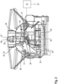
- a first and second conveyor screw 29, 30 are visible, each of which is in its working position.
- the first conveyor screw 29 is surrounded radially on the outside by a pipe 31 extending over the length of the first conveyor screw 29.
- the pipe 31 comprises an opening 32 through which crop 6 can be conveyed into the crop tank 3 by means of the first conveyor screw 29.
- a base 33 of the first conveyor screw 29 is mounted on the wall 25 adjacent to the crop inlet opening 24 in order to place the first conveyor screw 29 in front of the crop inlet opening 24 such that crop 6 conveyed through the crop inlet opening 24 can be taken up by the first conveyor screw 29.
- an open end of the pipe 31 can be placed immediately in front of the crop inlet opening 24.
- the first conveyor screw 29 can be directly or indirectly coupled to a drive of the grain elevator 19 in order to be forcibly coupled to the grain elevator 19.
- the first conveyor screw 29 is pivotably arranged on the base 33.
- the gradient of the first conveyor screw 29 here is at least 30 degrees, preferably approximately 45 degrees.
- the discharge side 34 is placed centrally above the open top of the crop tank 3.
- the second conveyor screw 30 extends vertically within the crop tank 3 and is positioned centrally within the crop tank 3.
- the first conveyor screw 29 is in conveying connection with the second conveyor screw 30.
- the intended operating state of the second conveyor screw 30 it conveys the crop 6 starting from its receiving area 35 in a vertical direction.
- the second conveyor screw 30 is driven separately from the first conveyor screw 29.
- the second conveyor screw 30 is coupled to a drive unit 38, wherein the drive unit 38 is arranged directly on the shaft 36 of the second conveyor screw 30, which is surrounded radially on the outside by screw turns 37.
- the drive unit 38 is provided and set up to put the second conveyor screw 30 into a rotating state.
- the drive unit 38 is designed as a hydraulic motor.
- the harvesting machine 1 comprises a Fig. 2 schematically illustrated control device 47, which is provided and configured to control the drive unit 38.
- the grain elevator 19 comprises a housing 39 which largely encloses the endlessly rotating conveyor chain 23, which is driven and deflected by a lower and upper chain or drive wheel 42 arranged in the crop receiving area 40 and in the crop delivery area 41.
- the housing 39 has openings through which the crop is fed in and discharged.
- Flat blades 22 are arranged on the endlessly rotating conveyor chain 23 at equal distances from one another.
- the conveying direction is indicated by arrows FR.
- the grain elevator 19 comprises a guide section 43 which guides the mass flow of crop 6 conveyed by the grain elevator 19 to the crop inlet opening 24 of the crop tank 3.
- Arrows GS illustrate the flow path of the mass or crop flow moving along the guide section 43 and a sensor surface 44.
- a mass flow sensor 45 is arranged on the guide section 43.
- the mass flow sensor 45 comprises a force measuring cell 46 which is assigned to the sensor surface 44.
- the mass flow guided along the guide surface exerts a force on the sensor surface 44 which is measured by means of the force measuring cell 46.
- the control device 47 is connected to the mass flow sensor 45 in a signal-transmitting manner.
- the mass flow or the throughput of the mass flow is determined in the control device 47 using the measured values S1 of the mass flow sensor 45. Details of the mass flow sensor 45 and the determination of the throughput of the mass flow are given in the EP3 301 407 B1 disclosed, the disclosure content of which is hereby fully incorporated into this application.
- the mass flow determined by means of the mass flow sensor 45 is used by the control device 47 to control the drive unit 38 of the second conveyor screw 30.
- the control device 47 is set up in such a way that so that it adapts a speed of the drive unit 38 and thus a speed of the second conveyor screw 30 to the mass flow as required.
- the control device 47 regulates the speed of the drive unit 38 in such a way that a conveying capacity or the speed of the second conveyor screw 30 is proportional to the determined mass flow.
- the mass flow conveyed by the second conveyor screw 30 thus corresponds essentially to the mass flow conveyed by the first conveyor screw 29 and the grain elevator 19. The required drive power of the second conveyor screw 30 and the wear of the same are thereby significantly reduced.
- the second conveyor screw 30 is not designed with pipes. Accordingly, the second conveyor screw 30 can radially outside surrounding crop 6 enter the envelope circle of the screw turns 37 of the second conveyor screw 30 and be conveyed by it in a vertical direction. Unlike the upstream first conveyor screw 29 and the grain elevator 19, the second conveyor screw 30 conveys the mass flow corresponding to its conveying capacity in a vertical direction from a certain fill level of the crop 6 within the crop tank 3. The regulation of the speed depending on the mass flow conveyed in the grain elevator 19 thus reduces the amount of crop 6 that is conveyed in a circle by the second conveyor screw 30 within the crop tank 3.
- the control device 47 regulates the speed of the second conveyor screw 30 such that it is driven at a preset minimum speed until the crop 6 in the crop tank 3 has reached a defined fill level 48.
- the control device 47 regulates the speed of the drive unit 38 or the speed of the second conveyor screw 30 depending on the mass flow determined in the grain elevator 19 by means of the mass flow sensor 45, wherein the speed is greater than the minimum speed after the fill level 48 is exceeded.
- the defined fill level 48 corresponds to the height of the lower end 49 of the second conveyor screw 30.
- the second conveyor screw 30 is operated at a minimum speed until the crop 6 in the crop tank 3 has reached the lower end 49 of the second conveyor screw 30.
- the speed of the second conveyor screw 30 is regulated depending on the mass flow sensor 45 or the mass flow determined in the grain elevator 19.
- the lower end 49 of the second conveyor screw 30 is to be understood in the sense of the present invention as the end which faces the bottom 50 of the crop tank 3.
- a fill level sensor 51 can be arranged at the level of the lower end 49 of the second conveyor screw 30 to monitor the level of the crop 6 in the crop tank 3. Before the crop 6 in the crop tank 3 reaches the lower end 49 of the second conveyor screw 30, there is no need to convey the crop 6 in a vertical direction by means of the second filling screw 30, so that drive power is saved by driving it at a minimum speed.
Landscapes
- Life Sciences & Earth Sciences (AREA)
- Environmental Sciences (AREA)
- Engineering & Computer Science (AREA)
- Mechanical Engineering (AREA)
- Screw Conveyors (AREA)
Abstract
Description
- Die vorliegende Erfindung betrifft eine Erntemaschine wie etwa einen Mähdrescher, und zwar insbesondere die Befüllung eines Ernteguttanks der Erntemaschine, sowie eine dafür ausgebildete Förderschnecke.
- Da sich beim Dreschen das Korn von Nichtkornbestanteilen des Ernteguts nach unten absetzt, muss es anschließend aufwärts befördert werden, um einen Ernteguttank des Mähdreschers zu befüllen. Hierzu dient oft ein Elevator mit an einer umlaufenden Kette umlaufenden Schaufeln, die am Boden des Dreschwerks gesammeltes Korn aufnehmen, anheben und über eine Korneinlassöffnung in einer Wand des Ernteguttanks in letzteren abgeben. Auf diese Weise kann der Ernteguttank nicht höher befüllt werden als bis zur Unterkante der Korneinlassöffnung.
- Um das Aufnahmevermögen des Ernteguttanks vollständiger nutzen zu können, wird daher in
DE 10 2019 002 637 A1 eine erste Förderschnecke vorgeschlagen, die im Innern des Korntanks an der Korneinlassöffnung schwenkbar montiert, vom Elevator abgegebenes Korn aufnimmt und weiter anhebt. Eine zweite Förderschnecke steht mit der ersten Förderschnecke in Förderverbindung. Die zweite Förderschnecke ist im Ernteguttank senkrecht angeordnet und fördert das von der ersten Förderschnecke angelieferte Erntegut weiter senkrecht nach oben. - Die Förderleistung der ersten und zweiten Förderschnecke ist üblicherweise auf die maximal mögliche Durchsatzleistung ausgelegt. Diese Durchsatzleistung wird allerdings nur zu einem geringen Zeitanteil des jährlichen Einsatzspektrums erreicht. Viele Maschinen erreichen diese Durchsätze aufgrund ihrer Einsatzbedingungen überhaupt nicht.
- Hieraus ergibt sich ein erhöhter Verschleiß der Förderschnecken. Zusätzlich erfolgt regelmäßig eine Leistungsabnahme der Förderschnecken die für die vorliegenden Erntebedingungen nicht erforderlich ist.
- Es ist deshalb Aufgabe der Erfindung, die beschriebenen Nachteile des Standes der Technik zu vermeiden und insbesondere die Befüllung eines Ernteguttanks einer Erntemaschine an verschiedene Erntebedingungen anpassbar auszuführen.
- Diese Aufgabe wird erfindungsgemäß durch die kennzeichnenden Merkmale des Anspruchs 1 gelöst.
- Gemäß dem Anspruch 1 wird eine Erntemaschine vorgeschlagen, umfassend einen Ernteguttank mit einer tankinternen ersten Förderschnecke, die sich von einer Guteinlassöffnung an einer Wand des Ernteguttanks ins Innere des Ernteguttanks erstreckt, eine tankinterne zweite Förderschnecke, wobei die zweite Förderschnecke in Förderverbindung mit der ersten Förderschnecke steht, eine Antriebseinheit, wobei die Antriebseinheit trieblich mit der zweiten Förderschnecke verbunden ist, einen Massenstromsensor zur Ermittlung eines Massenstroms, eine Steuerungseinrichtung zur Ansteuerung der Antriebseinheit, wobei die Steuerungseinrichtung derart eingerichtet ist, sodass diese eine Drehzahl der Antriebseinheit in Abhängigkeit des mittels des Massenstromsensors ermittelten Massenstroms ansteuert.
- Die Erfindung hat viele Vorteile. Die Förderleistung der zweiten Förderschnecke ist an die Durchsatzleistung der Erntemaschine angepasst. Dies ist besonders Vorteilhaft, da Erntemaschinen die maximale Durchsatzleistung in ihrem jährlichen Einsatzspektrum nur selten erreichen, sodass eine Anpassung der Drehzahl an die momentane Durchsatzleistung zu einer Reduzierung der für den Antrieb der zweiten Förderschnecke erforderlichen Antriebsleistung führt und Verschleißerscheinungen an der zweiten Förderschnecke erheblich reduziert. Die Regelung der Drehzahl der zweiten Förderschnecke in Abhängigkeit des Massenstromsensors bewirkt, dass die Förderleistung der zweiten Förderschnecke im Wesentlichen der Förderleistung der ersten Förderschnecke entspricht. An der zweiten Förderschnecke auftretende Blindleistung wird vermieden. Als Massenstrom ist die Erntegutmenge zu verstehen, die von einem Arbeitsaggregat der Erntemaschine gefördert wird. Besonders bevorzugt handelt es sich bei dem Arbeitsaggregat um den Kornelevator. Bei Identifikation eines geringen Massenstroms mittels des Massenstromsensors wird bevorzugt eine niedrigere Drehzahl an der Antriebseinheit eingestellt, als bei einer Identifikation eines größeren Massenstroms.
- Gemäß einer vorteilhaften Ausgestaltung kann die Antriebseinheit unmittelbar an der zweiten Förderschnecke angeordnet sein, wobei vorzugsweise die erste Förderschnecke separat zu der zweiten Förderschnecke angetrieben ist. Die Anordnung der Antriebseinheit unmittelbar an der zweiten Förderschnecke, wobei die Antriebseinheit unmittelbar mit der Welle der zweiten Förderschnecke gekoppelt ist, ermöglicht die Drehzahl der zweiten Förderschnecke unabhängig von der ersten Förderschnecke einzustellen. Mithin kann die Drehzahl der zweiten Förderschnecke optimal an die vorliegende Erntesituation sowie der in dem Ernteguttank befindlichen Erntegutmenge angepasst werden. Ferner ist der separate Antrieb der zweiten Förderschnecke besonders vorteilhaft, da diese somit unabhängig von der ersten Förderschnecke von einer vertikal ausgerichteten Arbeitsposition hin zu einer flacheren Parkposition verschwenkbar ist. Die Antriebseinheit kann als Hydraulikmotor ausgebildet sein.
- Eine weitere vorteilhafte Ausgestaltung sieht vor, dass die Steuerungseinrichtung die Drehzahl der Antriebseinheit derart regelt, sodass die Drehzahl der zweiten Förderschnecke eine konstante Mindestdrehzahl aufweist bis eine dem Ernteguttank zugeführte Erntegutmenge eine definierte Füllstandshöhe erreicht und nach Überschreiten der definierten Füllstandshöhe die Drehzahl der zweiten Förderschnecke in Abhängigkeit des Massenstromsensors geregelt ist. Die zweite Förderschnecke ist dazu vorgesehen und eingerichtet, das Erntegut über eine mittels der ersten Förderschnecke erreichbare Füllstandshöhe hinaus weiter zu befüllen. Demgemäß ist der Bedarf einer Förderung des Ernteguts erst ab einer gewissen Füllstandshöhe innerhalb des Ernteguttanks erforderlich. Dennoch ist es besonders vorteilhaft die zweite Förderschnecke bis zum Erreichen der Füllstandshöhe nicht im Stillstand zu lassen, sondern mit einer Mindestdrehzahl zu betreiben. Von der ersten Förderschnecke in Richtung der zweiten Förderschnecke geleitetes Erntegut wird von den Schneckenwindungen der zweiten Förderschnecke umgeleitet. Bei einer ungünstigen Stellung der zweiten Förderschnecke kann das Erntegut fortwährend gegen ein Korntankfenster geleitet werden. Das Korntankfenster gibt einer Person innerhalb der Fahrzeugkabine einen Einblick in den Korntank, wobei gegen das Korntankfenster umgeleitetes Erntegut störende Geräusche in der Fahrerkabine erzeugen kann. Das Betreiben der zweiten Förderschnecke mit der Mindestdrehzahl vermeidet, dass Erntegut fortwährend gegen die Fahrerkabine geleitet wird.
- Besonders bevorzugt ist es, wenn die definierte Füllstandshöhe einer Höhe des unteren Endes der zweiten Förderschnecke entspricht. Da erst ab Erreichen dieser Füllstandshöhe die zweite Förderschnecke in dem Ernteguttank befindliches Erntegut wirksam in vertikaler Richtung befördert.
- Um Erntegut sicher von einem Kornelevator übernehmen zu können und verlustarm fördern zu können, sollte die erste Förderschnecke von einem Rohr umgeben sein, wobei das Rohr eine Öffnung aufweist, die den Ausstritt von Erntegut in den Ernteguttank erlaubt. Dadurch, dass die erste Förderschnecke von einem Rohr umgeben ist, wird der zweiten Förderschnecke auch im Wesentlichen der von dem Massenstromsensor ermittelte Massenstrom zugeführt, sodass die Drehzahl der zweiten Förderschnecke optimal an den dieser zugeführten Massenstrom anpassbar ist.
- Eine vorteilhafte Weiterbildung sieht vor, dass die zweite Förderschnecke nicht verrohrt ist. Das heißt, dass die zweite Förderschnecke entlang ihrer Länge von keinem Rohr umgeben ist. Derartige unverrohrte zweite Förderschnecken werden häufig bei Erntemaschinen innerhalb des Ernteguttanks eingesetzt. Besonders für derartige unverrohrte zweite Förderschnecken ist die massenstromabhängige Drehzahlregelung besonders vorteilhaft, zumal ab der definierten Füllstandshöhe die zweite Förderschnecke zumindest abschnittsweise von Erntegut umgeben ist, sodass bereits in dem Ernteguttank befindliches Erntegut in den Hüllkreis der zweiten Förderschnecke gelangen kann und von dieser erneut in vertikale Richtung befördert wird. Es ist also möglich, dass Erntegut im Kreis gefördert wird. Die zweite Förderschnecke ist jedoch dazu vorgesehen, dass von der ersten Förderschnecke geförderte Erntegut anzunehmen und aus dem Abgabebereich der ersten Förderschnecke abzufördern um diese zu entlasten. Die Massenstromabhängige Regelung bewirkt nun, dass bei einer geringen Fördermenge der ersten Förderschnecke eine geringe Drehzahl an der zweiten Förderschnecke eingestellt ist. Zusätzliche, sogenannte Wühlarbeit, wobei bereits innerhalb des Ernteguttanks befindliches Erntegut in den Hüllkreis der zweiten Förderschnecke rutscht, wird zumindest reduziert.
- Gemäß einer vorteilhaften Ausgestaltung kann die Erntemaschine eine Fördervorrichtung, insbesondere Kornelevator, umfassen, welche zum Fördern des aus Erntegut bestehenden Massenstroms von einem tiefer gelegenen Erntegutannahmebereich zu einem höher gelegenen Erntegutabgabebereich vorgesehen und eingerichtet ist, wobei der Massenstromsensor zum Ermitteln des Massenstroms der Fördervorrichtung zugeordnet ist. Ein derartiger Kornelevator ist der ersten Förderschnecke vorgeordnet. Das von dem Kornelevator geförderte Erntegut wird verlustfrei der ersten Förderschnecke zugeführt und von dieser hin zu dem Annahmebereich der zweiten Förderschnecke befördert. Eine Anordnung des Massenstromsensors innerhalb des Kornelevators ist somit besonders geeignet, um den Massenstrom zu bestimmen, welcher der zweiten Förderschnecke zugeführt wird.
- Weitere vorteilhafte Ausgestaltungen sind Gegenstand weiterer Unteransprüche und werden nachfolgend an Hand eines in mehreren Figuren dargestellten Ausführungsbeispiels beschrieben. Es zeigen:
- Figur 1
- einen schematischen Schnitt durch einen Mähdrescher mit Förderschnecke gemäß der Erfindung;
- Figur 2
- einen schematischen Schnitt durch den Ernteguttank eines Mähdreschers;
- Figur 3
- eine Teilansicht eines Kornelevators eines Mähdreschers.
-
Fig. 1 zeigt einen schematischen Längsschnitt durch eine als Mähdrescher ausgebildete Erntemaschine 1 mit einer faltbaren Erweiterungsvorrichtung 2 zur Vergrößerung des Volumens eines Ernteguttanks 3. Der Mähdrescher ist frontseitig mit einem Schneidwerk 4 ausgestattet, das an einem Schrägförderer 5 angeordnet ist. Mit dem Schneidwerk 4 nimmt der Mähdrescher das Erntegut 6 auf und führt es dem Schrägförderer 5 zu. Der Schrägförderer 5 übergibt das Erntegut 6 an ein nachgeschaltetes Dreschwerk 7. Das Dreschwerk 7 bereitet das Erntegut 6 auf, wobei es in ein Korn-Spreu-Gemisch 8 und einen aus ausgedroschenen Halmen bestehenden Gutstrom 9 unterteilt wird. Das Korn-Spreu-Gemisch 8 wird über einen Vorbereitungsboden 10 direkt zu einer Reinigungseinrichtung 11 gefördert, die das Korn 12 von den Nichtkornbestandteilen 13, das heißt von Halm- und Spreuteilen trennt. - Hinter dem Dreschwerk 7 ist eine entgegen dem Uhrzeigersinn rotierende Wendetrommel 14 angeordnet, die den aus ausgedroschenen Halmen bestehenden Gutstrom 9 auf einen Hordenschüttler 15 fördert. Der Hordenschüttler 15 trennt noch im Gutstrom 9 vorhandenes Korn 12, Kurzstroh 16 und Spreu 17, die über einen Rücklaufboden 18 ebenfalls in die Reinigungseinrichtung 11 gelangen. Die von der Reinigungseinrichtung 11 abgetrennten Körner 12 fördert eine als Kornelevator 19 ausgebildete Fördervorrichtung 52 in den Ernteguttank 3.
- Der Kornelevator 19 umfasst eine mit Schaufeln 22 bestückte, endlos umlaufende Förderkette 23. Die Schaufeln 22 übernehmen das Korn 12 von der Reinigungseinrichtung 11 und fördern es in einem Schacht aufwärts bis zu einer Guteinlassöffnung 24 in einer Wand 25 des Ernteguttanks 3.
- Der Ernteguttank 3 ist als ein Behälter mit im Wesentlichen rechteckförmiger Grundfläche ausgeführt und hinter einer Fahrerkabine 26 des Mähdreschers angeordnet. Der Ernteguttank 3 weist an seiner Oberseite eine Öffnung 20 auf, an Oberkanten 21 seiner Wände sind mehrere die Erweiterungsvorrichtung 2 bildende plattenförmige Elemente 27, 28 angelenkt. Die Platten 27, 28 sind zwischen einer über der Öffnung miteinander überlappenden geschlossenen Position und einer in
Fig. 1 gezeigten Arbeitsstellung schwenkbar, in der die Erweiterungsvorrichtung 2 den Ernteguttank 3 nach oben trichterförmig erweitert. - In der Schnittansicht der
Fig. 2 sind eine erste und zweite Förderschnecke 29, 30 ersichtlich, die sich jeweils in ihrer Arbeitsstellung befinden. Die erste Förderschnecke 29 ist radial außenseitig von einem sich über die Länge der ersten Förderschnecke 29 erstreckenden Rohr 31 umgeben. Auf der Auswurfseite 34 der ersten Förderschnecke 29 umfasst das Rohr 31 eine Öffnung 32, durch die mittels der ersten Förderschnecke 29 Erntegut 6 in den Ernteguttank 3 förderbar ist. Eine Basis 33 der ersten Förderschnecke 29 ist an der Wand 25 benachbart zur Guteinlassöffnung 24 montiert, um die erste Förderschneck 29 so vor der Guteinlassöffnung 24 zu platzieren, dass durch die Guteinlassöffnung 24 gefördertes Erntegut 6 von der ersten Förderschnecke 29 aufgenommen werden kann. Zu diesem Zweck kann ein offenes Ende des Rohrs 31 unmittelbar vor der Guteinlassöffnung 24 platziert sein. - Die erste Förderschnecke 29 kann an einem Antrieb des Kornelevators 19 mittelbar oder unmittelbar gekoppelt sein, um mit dem Kornelevator 19 zwangsweise trieblich gekoppelt zu sein. Mithin ist die Förderleistung der ersten Förderschnecke 29 automatisch an die Förderleistung des Kornelevators 19 angepasst. Die erste Förderschnecke 29 ist schwenkbar an der Basis 33 angeordnet. In der in
Fig. 2 gezeigten Arbeitsstellung der ersten Förderschnecke 29 sind das Rohr 31 und die darin verlaufende erste Förderschnecke 29 in eine ansteigende Stellung geschwenkt. Die Steigung der ersten Förderschnecke 29 beträgt hier wenigstens 30 Grad, vorzugsweise ca. 45 Grad. Die Auswurfseite 34 ist mittig über der offenen Oberseite des Ernteguttanks 3 platziert. Die zweite Förderschnecke 30 erstreckt sich vertikal innerhalb des Ernteguttanks 3 und ist mittig innerhalb des Ernteguttanks 3 positioniert. Die erste Förderschnecke 29 steht mit der zweiten Förderschnecke 30 in Förderverbindung. Das bedeutet im Sinne der vorliegenden Anmeldung, dass die erste und zweite Förderschnecke 29, 30 derart zueinander positioniert sind, sodass die erste Förderschnecke 29 das Erntegut 6 hin zu einem Annahmebereich 35 der zweiten Förderschnecke 30 fördert. Im bestimmungsgemäßen Betriebszustand der zweiten Förderschnecke 30 fördert diese das Erntegut 6 ausgehend von ihrem Annahmebereich 35 in eine vertikale Richtung. - Die zweite Förderschnecke 30 wird separat zu der ersten Förderschnecke 29 angetrieben. Die zweite Förderschnecke 30 ist trieblich mit einer Antriebseinheit 38 gekoppelt, wobei an der Welle 36 der zweiten Förderschnecke 30, die von Schneckenwindungen 37 radial außenseitig umgeben ist, unmittelbar die Antriebseinheit 38 angeordnet ist. Die Antriebseinheit 38 ist dazu vorgesehen und eingerichtet, die zweite Förderschnecke 30 in einen rotierenden Zustand zu versetzen. Die Antriebseinheit 38 ist als ein Hydraulikmotor ausgebildet. Weiterhin umfasst die Erntemaschine 1 eine in
Fig. 2 schematisch dargestellte Steuerungseinrichtung 47, welche zur Ansteuerung der Antriebseinheit 38 vorgesehen und eingerichtet ist. - In
Fig. 3 ist eine Teilansicht des Kornelevators 19 dargestellt. Der Kornelevator 19 umfasst ein Gehäuse 39, welches die endlos umlaufende Förderkette 23, die um jeweils ein im Erntegutannahmebereich 40 und im Erntegutabgabebereich 41 angeordnetes unteres und oberes Ketten- bzw. Antriebsrad 42 angetrieben und umgelenkt wird, weitgehend umschließt. Im Erntegutannahmebereich 40 sowie im Erntegutabgabebereich 41 weist das Gehäuse 39 Öffnungen auf, durch welche das Erntegut zugeführt und abgeführt wird. An der endlos umlaufenden Förderkette 23 sind gleichmäßig zueinander beabstandet flächige Schaufeln 22 angeordnet. Die Förderrichtung ist durch Pfeile FR gekennzeichnet. - Im Erntegutabgabebereich 41 umfasst der Kornelevator 19 einen Führungsabschnitt 43, der den von dem Kornelevator 19 geförderten aus Erntegut 6 bestehenden Massenstrom hin zu der Guteinlassöffnung 24 des Ernteguttanks 3 leitet. Pfeile GS veranschaulichen den Strömungsverlauf des sich entlang des Führungsabschnitts 43 sowie einer Sensorfläche 44 bewegenden Massen- bzw. Erntegutstromes. An dem Führungsabschnitt 43 ist eine Massenstromsensor 45 angeordnet. Der Massenstromsensor 45 umfasst eine Kraftmesszelle 46, die der Sensorfläche 44 zugeordnet ist. Der entlang der Führungsfläche geleitete Massenstrom wirkt auf die Sensorfläche 44 eine Kraft aus, die mittels der Kraftmesszelle 46 gemessen werden. Die Steuerungseinrichtung 47 ist in signalübertragender Weise mit dem Massenstromsensor 45 verbunden. Mittels der Messwerte S1 des Massenstromsensors 45 wird in der Steuerungseinrichtung 47 der Massenstrom bzw. der Durchsatz des Massenstroms bestimmt. Details zu dem Massenstromsensor 45 sowie der Bestimmung des Durchsatzes des Massenstroms sind in der
EP 3 301 407 B1 offenbart, dessen Offenbarungsgehalt hiermit vollumfänglich in diese Anmeldung aufgenommen ist. - Der mittels des Massenstromsensor 45 ermittelte Massenstrom wird von der Steuerungseinrichtung 47 zur Ansteuerung der Antriebseinheit 38 der zweiten Förderschnecke 30 verwendet. Hierfür ist die Steuerungseinrichtung 47 derart eingerichtet, sodass diese eine Drehzahl der Antriebseinheit 38 und somit eine Drehzahl der zweiten Förderschnecke 30 bedarfsweise an den Massenstrom anpasst. Hier und vorzugsweise regelt die Steuerungseinrichtung 47 die Drehzahl der Antriebseinheit 38 derart, sodass eine Förderleistung bzw. die Drehzahl der zweiten Förderschnecke 30 proportional zu dem ermittelten Massenstrom ist. Der von der zweiten Förderschnecke 30 geförderte Massenstrom entspricht somit im Wesentlichen dem von der ersten Förderschnecke 29 und dem Kornelevator 19 geförderten Massenstrom. Die benötigte Antriebsleistung der zweiten Förderschnecke 30 sowie der Verschleiß selbiger wird hierdurch deutlich reduziert.
- Die zweite Förderschnecke 30 ist nicht verrohrt ausgebildet. Demgemäß kann die zweite Förderschnecke 30 radial außenseitig umgebendes Erntegut 6 in den Hüllkreis der Schneckenwindungen 37 der zweiten Förderschnecke 30 gelangen und von dieser in vertikaler Richtung gefördert werden. Anders als die vorgeschaltete erste Förderschnecke 29 und der Kornelevator 19 fördert die zweite Förderschnecke 30 ab einem gewissen Füllstand des Ernteguts 6 innerhalb des Ernteguttanks 3 den ihrer Förderleistung entsprechenden Massenstrom in vertikale Richtung. Die Regelung der Drehzahl in Abhängigkeit des im Kornelevators 19 geförderten Massenstroms reduziert somit die Menge von Erntegut 6, das von der zweiten Förderschnecke 30 innerhalb des Ernteguttanks 3 im Kreis gefördert wird.
- Hier und vorzugsweise regelt die Steuerungseinrichtung 47 die Drehzahl der zweiten Förderschnecke 30 derart, sodass diese mit einer voreingestellten Mindestdrehzahl angetrieben wird, bis das in dem Ernteguttank 3 befindliche Erntegut 6 eine definierte Füllstandshöhe 48 erreicht hat. Nachdem das in dem Ernteguttank 3 befindliche Erntegut 6 die Füllstandshöhe 48 überschritten hat, regelt die Steuerungseinrichtung 47 die Drehzahl der Antriebseinheit 38 bzw. die Drehzahl der zweiten Förderschnecke 30 in Abhängigkeit des in dem Kornelevator 19 mittels des Massenstromsensors 45 ermittelten Massenstroms, wobei die Drehzahl nach überschreiten der Füllstandshöhe 48 größer ist, als die Mindestdrehzahl. Hierbei entspricht die definierte Füllstandshöhe 48 der Höhe des unteren Endes 49 der zweiten Förderschnecke 30. Mit anderen Worten ausgedrückt, wird die zweite Förderschnecke 30 mit einer Mindestdrehzahl betrieben, bis das in dem Ernteguttank 3 befindliche Erntegut 6 das untere Ende 49 der zweiten Förderschnecke 30 erreicht hat. Nachdem diese Füllstandshöhe 48 das untere Ende 49 der zweiten Förderschnecke 30 erreicht hat, wird die Drehzahl der zweiten Förderschnecke 30 in Abhängigkeit des Massenstromsensors 45 bzw. des in dem Kornelevator 19 ermittelten Massenstroms geregelt. Als das untere Ende 49 der zweiten Förderschnecke 30 ist im Sinne der vorliegenden Erfindung das Ende zu verstehen, welches dem Boden 50 des Ernteguttanks 3 zugewandt ist. Zum Ermitteln der Füllstandshöhe 48 des in dem Ernteguttank 3 befindlichen Ernteguts 6 kann auf Höhe des unteren Endes 49 der zweiten Förderschnecke 30 ein Füllstandsensor 51 angeordnet sein. Bevor das in dem Ernteguttank 3 befindliche Erntegut 6 das untere Ende 49 der zweiten Förderschnecke 30 erreicht, besteht kein Bedarf das Erntegut 6 mittels der zweiten Füllschnecke 30 in vertikale Richtung zu befördern, sodass durch das Antreiben mit einer Mindestdrehzahl Antriebsleistung eingespart wird. Dennoch ist das Betreiben der zweiten Förderschnecke 30 mit der geringen Mindestdrehzahl besonders vorteilhaft, da hierdurch von der ersten Förderschnecke 29 gegen die zweite Förderschnecke 30 gefördertes Erntegut gleichmäßiger innerhalb des Ernteguttanks 3 verteilt wird. Auch wird vermieden, dass durch eine ungünstige Ausrichtung der Schneckenwindungen 37 der zweiten Förderschnecke 30 gegen die zweite Förderschnecke 30 gefördertes Erntegut 6 fortwährend in Richtung einer hier nicht dargestellten Kabinenscheibe umgeleitet wird und damit einhergehend für eine in der Kabine 26 befindliche Person störende Geräusche auftreten.
-
1 Erntemaschine 34 Auswurfseite 2 Erweiterungsvorrichtung 35 Annahmebereich 3 Ernteguttank 36 Welle 4 Schneidwerk 37 Schneckenwindungen 5 Schrägförderer 38 Antriebseinheit 6 Erntegut 39 Gehäuse 7 Dreschwerk 40 Erntegutannahmebereich 8 Korn-Spreu-Gemisch 41 Erntegutabgabebereich 9 Gutstrom 42 Kettenrad 10 Vorbereitungsboden 43 Führungsabschnitt 11 Reinigungseinrichtung 44 Sensorfläche 12 Korn 45 Massenstromsensor 13 Nichtkornbestandteile 46 Kraftmesszelle 14 Wendetrommel 47 Steuerungseinrichtung 15 Hordenschüttler 48 Füllstandshöhe 16 Kurzstroh 49 Ende zweite Förderschnecke 17 Spreu 50 Boden 18 Rücklaufboden 51 Füllstandsensor 19 Kornelevator 52 Fördervorrichtung 20 Öffnung 21 Oberkante S1 Messwerte 22 Schaufel GS Pfeil 23 Förderkette FR Pfeil 24 Guteinlassöffnung 25 Wand 26 Fahrerkabine 27 Platte 28 Platte 29 Erste Förderschnecke 30 Zweite Förderschnecke 31 Rohr 32 Öffnung 33 Basis
Claims (7)
- Erntemaschine (1) umfassend- einen Ernteguttank (3) mit einer tankinternen ersten Förderschnecke (29), die sich von einer Guteinlassöffnung (24) an einer Wand (25) des Ernteguttanks (3) ins Innere des Ernteguttanks (3) erstreckt;- eine tankinterne zweite Förderschnecke (30), wobei die zweite Förderschnecke (30) in Förderverbindung mit der ersten Förderschnecke (29) steht;- eine Antriebseinheit (38), wobei die Antriebseinheit (38) trieblich mit der zweiten Förderschnecke (30) verbunden ist;- einen Massenstromsensor (45) zur Ermittlung eines Massenstroms;- eine Steuerungseinrichtung (47) zur Ansteuerung der Antriebseinheit (38);dadurch gekennzeichnet, dass
die Steuerungseinrichtung (47) derart eingerichtet ist, sodass diese eine Drehzahl der Antriebseinheit (38) in Abhängigkeit des mittels des Massenstromsensors (45) ermittelten Massenstroms ansteuert. - Erntemaschine (1) nach Anspruch 1, dadurch gekennzeichnet, dass die Antriebseinheit (38) unmittelbar an der zweiten Förderschnecke (30) angeordnet ist, wobei vorzugsweise die erste Förderschnecke (29) separat zu der zweiten Förderschnecke (30) angetrieben ist.
- Erntemaschine (1) nach einem der Ansprüche 1 oder 2, dadurch gekennzeichnet, dass die Steuerungseinrichtung (47) die Drehzahl der Antriebseinheit (38) derart regelt, sodass die Drehzahl der zweiten Förderschnecke (30) eine konstante Mindestdrehzahl aufweist bis eine dem Ernteguttank (3) zugeführte Erntegutmenge eine definierte Füllstandshöhe (48) erreicht und nach Überschreiten der definierten Füllstandshöhe (48) die Drehzahl der zweiten Förderschnecke (30) in Abhängigkeit des Massenstromsensors (45) geregelt ist.
- Erntemaschine (1) nach Anspruch 3, dadurch gekennzeichnet, dass die definierte Füllstandshöhe (48) einer Höhe des unteren Endes (49) der zweiten Förderschnecke (30) entspricht.
- Erntemaschine (1) nach einem der Ansprüche 1 bis 4, dadurch gekennzeichnet, dass die erste Förderschnecke (29) wenigstens auf einem Teil ihrer Länge von einem Rohr (31) umgeben ist, wobei das Rohr (31) eine Öffnung (32) aufweist, die den Ausstritt von Erntegut (6) in den Ernteguttank (3) erlaubt.
- Erntemaschine (1) nach einem der Ansprüche 1 bis 5, dadurch gekennzeichnet, dass die zweite Förderschnecke (30) nicht verrohrt ist.
- Erntemaschine (1) nach einem der Ansprüche 1 bis 6, dadurch gekennzeichnet, dass die Erntemaschine (1) eine Fördervorrichtung (52), insbesondere Kornelevator (19), umfasst, welche zum Fördern des aus Erntegut (6) bestehenden Massenstroms von einem tiefer gelegenen Erntegutannahmebereich (40) zu einem höher gelegenen Erntegutabgabebereich (41) vorgesehen und eingerichtet ist, wobei der Massenstromsensor (45) zum Ermitteln des Massenstroms der Fördervorrichtung (52) zugeordnet ist.
Applications Claiming Priority (1)
| Application Number | Priority Date | Filing Date | Title |
|---|---|---|---|
| DE102023104330.7A DE102023104330A1 (de) | 2023-02-22 | 2023-02-22 | Erntemaschine |
Publications (2)
| Publication Number | Publication Date |
|---|---|
| EP4420506A1 true EP4420506A1 (de) | 2024-08-28 |
| EP4420506B1 EP4420506B1 (de) | 2025-10-01 |
Family
ID=89222748
Family Applications (1)
| Application Number | Title | Priority Date | Filing Date |
|---|---|---|---|
| EP23216552.2A Active EP4420506B1 (de) | 2023-02-22 | 2023-12-14 | Erntemaschine |
Country Status (2)
| Country | Link |
|---|---|
| EP (1) | EP4420506B1 (de) |
| DE (1) | DE102023104330A1 (de) |
Citations (5)
| Publication number | Priority date | Publication date | Assignee | Title |
|---|---|---|---|---|
| US4029228A (en) * | 1975-09-26 | 1977-06-14 | Allis-Chalmers Corporation | Self-raising bin loading auger for combines |
| US6248015B1 (en) * | 2000-01-27 | 2001-06-19 | New Holland North America, Inc. | Turret system on a bubble-up auger for an agricultural combine |
| EP3420794A1 (de) * | 2017-06-28 | 2019-01-02 | CLAAS Selbstfahrende Erntemaschinen GmbH | System zur ertragsmessung und verfahren zum betreiben eines systems zur ertragsmessung |
| EP3301407B1 (de) | 2016-09-29 | 2020-03-11 | CLAAS Selbstfahrende Erntemaschinen GmbH | Verfahren zur bestimmung eines aus schüttgut bestehenden massenstroms sowie steuer- und regelungsvorrichtung zur durchführung des verfahrens |
| EP3721695A1 (de) * | 2019-04-10 | 2020-10-14 | CLAAS Selbstfahrende Erntemaschinen GmbH | Erntemaschine und förderschnecke dafür |
-
2023
- 2023-02-22 DE DE102023104330.7A patent/DE102023104330A1/de active Pending
- 2023-12-14 EP EP23216552.2A patent/EP4420506B1/de active Active
Patent Citations (6)
| Publication number | Priority date | Publication date | Assignee | Title |
|---|---|---|---|---|
| US4029228A (en) * | 1975-09-26 | 1977-06-14 | Allis-Chalmers Corporation | Self-raising bin loading auger for combines |
| US6248015B1 (en) * | 2000-01-27 | 2001-06-19 | New Holland North America, Inc. | Turret system on a bubble-up auger for an agricultural combine |
| EP3301407B1 (de) | 2016-09-29 | 2020-03-11 | CLAAS Selbstfahrende Erntemaschinen GmbH | Verfahren zur bestimmung eines aus schüttgut bestehenden massenstroms sowie steuer- und regelungsvorrichtung zur durchführung des verfahrens |
| EP3420794A1 (de) * | 2017-06-28 | 2019-01-02 | CLAAS Selbstfahrende Erntemaschinen GmbH | System zur ertragsmessung und verfahren zum betreiben eines systems zur ertragsmessung |
| EP3721695A1 (de) * | 2019-04-10 | 2020-10-14 | CLAAS Selbstfahrende Erntemaschinen GmbH | Erntemaschine und förderschnecke dafür |
| DE102019002637A1 (de) | 2019-04-10 | 2020-10-15 | Claas Selbstfahrende Erntemaschinen Gmbh | Erntemaschlne und Förderschnecke dafür |
Also Published As
| Publication number | Publication date |
|---|---|
| DE102023104330A1 (de) | 2024-08-22 |
| EP4420506B1 (de) | 2025-10-01 |
Similar Documents
| Publication | Publication Date | Title |
|---|---|---|
| DE2628706C2 (de) | ||
| DE602004005553T2 (de) | System zum Ausstossen von Ernteresten aus einem Mähdrescher | |
| DE2233018A1 (de) | Maehdrescher der axialflussbauart | |
| EP1243173B1 (de) | Schrägfördererkraftsensor zur Erfassung des Gutdurchsatzes eines Mähdreschers | |
| DE2725588C2 (de) | ||
| EP0521280B1 (de) | Axialabscheider | |
| EP3721695B1 (de) | Erntemaschine und förderschnecke dafür | |
| DE2943839A1 (de) | Maehdrescher mit axialer durchlaufrichtung | |
| EP3391725A1 (de) | Schneckenfördererzusammenbau für einen mähdrescher | |
| DD139379A5 (de) | Laengsfluss-maehdrescher | |
| DE2948272A1 (de) | Maehdrescher | |
| EP0039427B1 (de) | Fördervorrichtung zum Befüllen mit Erntegut des Sammelbehälters eines Mähdreschers | |
| DE2943840A1 (de) | Maehdrescher | |
| DE3025380A1 (de) | Maehdrescher | |
| DE102005027726A1 (de) | Radialgebläse für eine Reinigungseinrichtung für einen Mähdrescher | |
| EP4420506B1 (de) | Erntemaschine | |
| EP1214873A1 (de) | Einlauf einer Axialdreschmaschine | |
| DE102020123939A1 (de) | Rotierender siebkasten | |
| EP4470358A1 (de) | Selbstfahrender mähdrescher mit einem vorsatzgerät | |
| DE102020205422A1 (de) | Schneckenfördererzusammenbau zur Entladung eines Korntanks eines Mähdreschers | |
| EP2078451B1 (de) | Mähdrescher | |
| EP0109518B1 (de) | Schneckenfördereinrichtung | |
| EP1310151B1 (de) | Fördereinrichtung zur Befüllung eines Korntranks eines Mähdreschers und Überkehrförderer | |
| DE102015212608B4 (de) | Erntegutresteverteileinrichtung für einen Mähdrescher | |
| DE2830069A1 (de) | Maehdrescher, der nach dem axialflussprinzip arbeitet |
Legal Events
| Date | Code | Title | Description |
|---|---|---|---|
| PUAI | Public reference made under article 153(3) epc to a published international application that has entered the european phase |
Free format text: ORIGINAL CODE: 0009012 |
|
| STAA | Information on the status of an ep patent application or granted ep patent |
Free format text: STATUS: THE APPLICATION HAS BEEN PUBLISHED |
|
| AK | Designated contracting states |
Kind code of ref document: A1 Designated state(s): AL AT BE BG CH CY CZ DE DK EE ES FI FR GB GR HR HU IE IS IT LI LT LU LV MC ME MK MT NL NO PL PT RO RS SE SI SK SM TR |
|
| P01 | Opt-out of the competence of the unified patent court (upc) registered |
Free format text: CASE NUMBER: APP_50573/2024 Effective date: 20240906 |
|
| STAA | Information on the status of an ep patent application or granted ep patent |
Free format text: STATUS: REQUEST FOR EXAMINATION WAS MADE |
|
| 17P | Request for examination filed |
Effective date: 20250228 |
|
| GRAP | Despatch of communication of intention to grant a patent |
Free format text: ORIGINAL CODE: EPIDOSNIGR1 |
|
| STAA | Information on the status of an ep patent application or granted ep patent |
Free format text: STATUS: GRANT OF PATENT IS INTENDED |
|
| RIC1 | Information provided on ipc code assigned before grant |
Ipc: A01D 41/12 20060101ALI20250410BHEP Ipc: A01F 12/46 20060101ALI20250410BHEP Ipc: A01D 41/127 20060101AFI20250410BHEP |
|
| INTG | Intention to grant announced |
Effective date: 20250423 |
|
| GRAS | Grant fee paid |
Free format text: ORIGINAL CODE: EPIDOSNIGR3 |
|
| GRAA | (expected) grant |
Free format text: ORIGINAL CODE: 0009210 |
|
| STAA | Information on the status of an ep patent application or granted ep patent |
Free format text: STATUS: THE PATENT HAS BEEN GRANTED |
|
| AK | Designated contracting states |
Kind code of ref document: B1 Designated state(s): AL AT BE BG CH CY CZ DE DK EE ES FI FR GB GR HR HU IE IS IT LI LT LU LV MC ME MK MT NL NO PL PT RO RS SE SI SK SM TR |
|
| REG | Reference to a national code |
Ref country code: GB Ref legal event code: FG4D Free format text: NOT ENGLISH Ref country code: CH Ref legal event code: F10 Free format text: ST27 STATUS EVENT CODE: U-0-0-F10-F00 (AS PROVIDED BY THE NATIONAL OFFICE) Effective date: 20251001 |
|
| REG | Reference to a national code |
Ref country code: IE Ref legal event code: FG4D Free format text: LANGUAGE OF EP DOCUMENT: GERMAN |
|
| REG | Reference to a national code |
Ref country code: DE Ref legal event code: R096 Ref document number: 502023001903 Country of ref document: DE |
|
| PGFP | Annual fee paid to national office [announced via postgrant information from national office to epo] |
Ref country code: DE Payment date: 20251211 Year of fee payment: 3 |
|
| PGFP | Annual fee paid to national office [announced via postgrant information from national office to epo] |
Ref country code: AT Payment date: 20260113 Year of fee payment: 3 |
|
| PGFP | Annual fee paid to national office [announced via postgrant information from national office to epo] |
Ref country code: BE Payment date: 20251219 Year of fee payment: 3 |
|
| REG | Reference to a national code |
Ref country code: NL Ref legal event code: MP Effective date: 20251001 |
|
| PG25 | Lapsed in a contracting state [announced via postgrant information from national office to epo] |
Ref country code: NL Free format text: LAPSE BECAUSE OF FAILURE TO SUBMIT A TRANSLATION OF THE DESCRIPTION OR TO PAY THE FEE WITHIN THE PRESCRIBED TIME-LIMIT Effective date: 20251001 |
|
| PG25 | Lapsed in a contracting state [announced via postgrant information from national office to epo] |
Ref country code: ES Free format text: LAPSE BECAUSE OF FAILURE TO SUBMIT A TRANSLATION OF THE DESCRIPTION OR TO PAY THE FEE WITHIN THE PRESCRIBED TIME-LIMIT Effective date: 20251001 |
|
| REG | Reference to a national code |
Ref country code: LT Ref legal event code: MG9D |
|
| PG25 | Lapsed in a contracting state [announced via postgrant information from national office to epo] |
Ref country code: NO Free format text: LAPSE BECAUSE OF FAILURE TO SUBMIT A TRANSLATION OF THE DESCRIPTION OR TO PAY THE FEE WITHIN THE PRESCRIBED TIME-LIMIT Effective date: 20260101 |
|
| PG25 | Lapsed in a contracting state [announced via postgrant information from national office to epo] |
Ref country code: FI Free format text: LAPSE BECAUSE OF FAILURE TO SUBMIT A TRANSLATION OF THE DESCRIPTION OR TO PAY THE FEE WITHIN THE PRESCRIBED TIME-LIMIT Effective date: 20251001 Ref country code: HR Free format text: LAPSE BECAUSE OF FAILURE TO SUBMIT A TRANSLATION OF THE DESCRIPTION OR TO PAY THE FEE WITHIN THE PRESCRIBED TIME-LIMIT Effective date: 20251001 |
|
| PG25 | Lapsed in a contracting state [announced via postgrant information from national office to epo] |
Ref country code: RS Free format text: LAPSE BECAUSE OF FAILURE TO SUBMIT A TRANSLATION OF THE DESCRIPTION OR TO PAY THE FEE WITHIN THE PRESCRIBED TIME-LIMIT Effective date: 20260101 |
|
| PG25 | Lapsed in a contracting state [announced via postgrant information from national office to epo] |
Ref country code: IS Free format text: LAPSE BECAUSE OF FAILURE TO SUBMIT A TRANSLATION OF THE DESCRIPTION OR TO PAY THE FEE WITHIN THE PRESCRIBED TIME-LIMIT Effective date: 20260201 |
|
| PG25 | Lapsed in a contracting state [announced via postgrant information from national office to epo] |
Ref country code: CZ Free format text: LAPSE BECAUSE OF FAILURE TO SUBMIT A TRANSLATION OF THE DESCRIPTION OR TO PAY THE FEE WITHIN THE PRESCRIBED TIME-LIMIT Effective date: 20251001 Ref country code: PT Free format text: LAPSE BECAUSE OF FAILURE TO SUBMIT A TRANSLATION OF THE DESCRIPTION OR TO PAY THE FEE WITHIN THE PRESCRIBED TIME-LIMIT Effective date: 20260202 |
|
| PG25 | Lapsed in a contracting state [announced via postgrant information from national office to epo] |
Ref country code: PL Free format text: LAPSE BECAUSE OF FAILURE TO SUBMIT A TRANSLATION OF THE DESCRIPTION OR TO PAY THE FEE WITHIN THE PRESCRIBED TIME-LIMIT Effective date: 20251001 |
|
| PG25 | Lapsed in a contracting state [announced via postgrant information from national office to epo] |
Ref country code: LV Free format text: LAPSE BECAUSE OF FAILURE TO SUBMIT A TRANSLATION OF THE DESCRIPTION OR TO PAY THE FEE WITHIN THE PRESCRIBED TIME-LIMIT Effective date: 20251001 |
|
| PG25 | Lapsed in a contracting state [announced via postgrant information from national office to epo] |
Ref country code: BG Free format text: LAPSE BECAUSE OF FAILURE TO SUBMIT A TRANSLATION OF THE DESCRIPTION OR TO PAY THE FEE WITHIN THE PRESCRIBED TIME-LIMIT Effective date: 20251001 |