EP4419366B1 - Inverse reifenmodellverstärkungsfunktion für ein schwerlastfahrzeug - Google Patents
Inverse reifenmodellverstärkungsfunktion für ein schwerlastfahrzeug Download PDFInfo
- Publication number
- EP4419366B1 EP4419366B1 EP22702474.2A EP22702474A EP4419366B1 EP 4419366 B1 EP4419366 B1 EP 4419366B1 EP 22702474 A EP22702474 A EP 22702474A EP 4419366 B1 EP4419366 B1 EP 4419366B1
- Authority
- EP
- European Patent Office
- Prior art keywords
- inverse
- tyre model
- wheel
- boost
- vehicle
- Prior art date
- Legal status (The legal status is an assumption and is not a legal conclusion. Google has not performed a legal analysis and makes no representation as to the accuracy of the status listed.)
- Active
Links
Images

Classifications
-
- B—PERFORMING OPERATIONS; TRANSPORTING
- B60—VEHICLES IN GENERAL
- B60K—ARRANGEMENT OR MOUNTING OF PROPULSION UNITS OR OF TRANSMISSIONS IN VEHICLES; ARRANGEMENT OR MOUNTING OF PLURAL DIVERSE PRIME-MOVERS IN VEHICLES; AUXILIARY DRIVES FOR VEHICLES; INSTRUMENTATION OR DASHBOARDS FOR VEHICLES; ARRANGEMENTS IN CONNECTION WITH COOLING, AIR INTAKE, GAS EXHAUST OR FUEL SUPPLY OF PROPULSION UNITS IN VEHICLES
- B60K28/00—Safety devices for propulsion-unit control, specially adapted for, or arranged in, vehicles, e.g. preventing fuel supply or ignition in the event of potentially dangerous conditions
- B60K28/10—Safety devices for propulsion-unit control, specially adapted for, or arranged in, vehicles, e.g. preventing fuel supply or ignition in the event of potentially dangerous conditions responsive to conditions relating to the vehicle
- B60K28/16—Safety devices for propulsion-unit control, specially adapted for, or arranged in, vehicles, e.g. preventing fuel supply or ignition in the event of potentially dangerous conditions responsive to conditions relating to the vehicle responsive to, or preventing, spinning or skidding of wheels
-
- B—PERFORMING OPERATIONS; TRANSPORTING
- B60—VEHICLES IN GENERAL
- B60T—VEHICLE BRAKE CONTROL SYSTEMS OR PARTS THEREOF; BRAKE CONTROL SYSTEMS OR PARTS THEREOF, IN GENERAL; ARRANGEMENT OF BRAKING ELEMENTS ON VEHICLES IN GENERAL; PORTABLE DEVICES FOR PREVENTING UNWANTED MOVEMENT OF VEHICLES; VEHICLE MODIFICATIONS TO FACILITATE COOLING OF BRAKES
- B60T8/00—Arrangements for adjusting wheel-braking force to meet varying vehicular or ground-surface conditions, e.g. limiting or varying distribution of braking force
- B60T8/17—Using electrical or electronic regulation means to control braking
- B60T8/1701—Braking or traction control means specially adapted for particular types of vehicles
- B60T8/1708—Braking or traction control means specially adapted for particular types of vehicles for lorries or tractor-trailer combinations
-
- B—PERFORMING OPERATIONS; TRANSPORTING
- B60—VEHICLES IN GENERAL
- B60T—VEHICLE BRAKE CONTROL SYSTEMS OR PARTS THEREOF; BRAKE CONTROL SYSTEMS OR PARTS THEREOF, IN GENERAL; ARRANGEMENT OF BRAKING ELEMENTS ON VEHICLES IN GENERAL; PORTABLE DEVICES FOR PREVENTING UNWANTED MOVEMENT OF VEHICLES; VEHICLE MODIFICATIONS TO FACILITATE COOLING OF BRAKES
- B60T8/00—Arrangements for adjusting wheel-braking force to meet varying vehicular or ground-surface conditions, e.g. limiting or varying distribution of braking force
- B60T8/17—Using electrical or electronic regulation means to control braking
- B60T8/172—Determining control parameters used in the regulation, e.g. by calculations involving measured or detected parameters
-
- B—PERFORMING OPERATIONS; TRANSPORTING
- B60—VEHICLES IN GENERAL
- B60T—VEHICLE BRAKE CONTROL SYSTEMS OR PARTS THEREOF; BRAKE CONTROL SYSTEMS OR PARTS THEREOF, IN GENERAL; ARRANGEMENT OF BRAKING ELEMENTS ON VEHICLES IN GENERAL; PORTABLE DEVICES FOR PREVENTING UNWANTED MOVEMENT OF VEHICLES; VEHICLE MODIFICATIONS TO FACILITATE COOLING OF BRAKES
- B60T8/00—Arrangements for adjusting wheel-braking force to meet varying vehicular or ground-surface conditions, e.g. limiting or varying distribution of braking force
- B60T8/17—Using electrical or electronic regulation means to control braking
- B60T8/175—Brake regulation specially adapted to prevent excessive wheel spin during vehicle acceleration, e.g. for traction control
-
- B—PERFORMING OPERATIONS; TRANSPORTING
- B60—VEHICLES IN GENERAL
- B60T—VEHICLE BRAKE CONTROL SYSTEMS OR PARTS THEREOF; BRAKE CONTROL SYSTEMS OR PARTS THEREOF, IN GENERAL; ARRANGEMENT OF BRAKING ELEMENTS ON VEHICLES IN GENERAL; PORTABLE DEVICES FOR PREVENTING UNWANTED MOVEMENT OF VEHICLES; VEHICLE MODIFICATIONS TO FACILITATE COOLING OF BRAKES
- B60T8/00—Arrangements for adjusting wheel-braking force to meet varying vehicular or ground-surface conditions, e.g. limiting or varying distribution of braking force
- B60T8/17—Using electrical or electronic regulation means to control braking
- B60T8/1755—Brake regulation specially adapted to control the stability of the vehicle, e.g. taking into account yaw rate or transverse acceleration in a curve
- B60T8/17552—Brake regulation specially adapted to control the stability of the vehicle, e.g. taking into account yaw rate or transverse acceleration in a curve responsive to the tyre sideslip angle or the vehicle body slip angle
-
- B—PERFORMING OPERATIONS; TRANSPORTING
- B60—VEHICLES IN GENERAL
- B60T—VEHICLE BRAKE CONTROL SYSTEMS OR PARTS THEREOF; BRAKE CONTROL SYSTEMS OR PARTS THEREOF, IN GENERAL; ARRANGEMENT OF BRAKING ELEMENTS ON VEHICLES IN GENERAL; PORTABLE DEVICES FOR PREVENTING UNWANTED MOVEMENT OF VEHICLES; VEHICLE MODIFICATIONS TO FACILITATE COOLING OF BRAKES
- B60T8/00—Arrangements for adjusting wheel-braking force to meet varying vehicular or ground-surface conditions, e.g. limiting or varying distribution of braking force
- B60T8/17—Using electrical or electronic regulation means to control braking
- B60T8/176—Brake regulation specially adapted to prevent excessive wheel slip during vehicle deceleration, e.g. ABS
- B60T8/1761—Brake regulation specially adapted to prevent excessive wheel slip during vehicle deceleration, e.g. ABS responsive to wheel or brake dynamics, e.g. wheel slip, wheel acceleration or rate of change of brake fluid pressure
- B60T8/17616—Microprocessor-based systems
-
- B—PERFORMING OPERATIONS; TRANSPORTING
- B60—VEHICLES IN GENERAL
- B60W—CONJOINT CONTROL OF VEHICLE SUB-UNITS OF DIFFERENT TYPE OR DIFFERENT FUNCTION; CONTROL SYSTEMS SPECIALLY ADAPTED FOR HYBRID VEHICLES; ROAD VEHICLE DRIVE CONTROL SYSTEMS FOR PURPOSES NOT RELATED TO THE CONTROL OF A PARTICULAR SUB-UNIT
- B60W10/00—Conjoint control of vehicle sub-units of different type or different function
- B60W10/04—Conjoint control of vehicle sub-units of different type or different function including control of propulsion units
-
- B—PERFORMING OPERATIONS; TRANSPORTING
- B60—VEHICLES IN GENERAL
- B60W—CONJOINT CONTROL OF VEHICLE SUB-UNITS OF DIFFERENT TYPE OR DIFFERENT FUNCTION; CONTROL SYSTEMS SPECIALLY ADAPTED FOR HYBRID VEHICLES; ROAD VEHICLE DRIVE CONTROL SYSTEMS FOR PURPOSES NOT RELATED TO THE CONTROL OF A PARTICULAR SUB-UNIT
- B60W10/00—Conjoint control of vehicle sub-units of different type or different function
- B60W10/18—Conjoint control of vehicle sub-units of different type or different function including control of braking systems
-
- B—PERFORMING OPERATIONS; TRANSPORTING
- B60—VEHICLES IN GENERAL
- B60W—CONJOINT CONTROL OF VEHICLE SUB-UNITS OF DIFFERENT TYPE OR DIFFERENT FUNCTION; CONTROL SYSTEMS SPECIALLY ADAPTED FOR HYBRID VEHICLES; ROAD VEHICLE DRIVE CONTROL SYSTEMS FOR PURPOSES NOT RELATED TO THE CONTROL OF A PARTICULAR SUB-UNIT
- B60W30/00—Purposes of road vehicle drive control systems not related to the control of a particular sub-unit, e.g. of systems using conjoint control of vehicle sub-units
- B60W30/18—Propelling the vehicle
- B60W30/18172—Preventing, or responsive to skidding of wheels
-
- B—PERFORMING OPERATIONS; TRANSPORTING
- B60—VEHICLES IN GENERAL
- B60T—VEHICLE BRAKE CONTROL SYSTEMS OR PARTS THEREOF; BRAKE CONTROL SYSTEMS OR PARTS THEREOF, IN GENERAL; ARRANGEMENT OF BRAKING ELEMENTS ON VEHICLES IN GENERAL; PORTABLE DEVICES FOR PREVENTING UNWANTED MOVEMENT OF VEHICLES; VEHICLE MODIFICATIONS TO FACILITATE COOLING OF BRAKES
- B60T2220/00—Monitoring, detecting driver behaviour; Signalling thereof; Counteracting thereof
- B60T2220/04—Pedal travel sensor, stroke sensor; Sensing brake request
-
- B—PERFORMING OPERATIONS; TRANSPORTING
- B60—VEHICLES IN GENERAL
- B60T—VEHICLE BRAKE CONTROL SYSTEMS OR PARTS THEREOF; BRAKE CONTROL SYSTEMS OR PARTS THEREOF, IN GENERAL; ARRANGEMENT OF BRAKING ELEMENTS ON VEHICLES IN GENERAL; PORTABLE DEVICES FOR PREVENTING UNWANTED MOVEMENT OF VEHICLES; VEHICLE MODIFICATIONS TO FACILITATE COOLING OF BRAKES
- B60T2230/00—Monitoring, detecting special vehicle behaviour; Counteracting thereof
- B60T2230/02—Side slip angle, attitude angle, floating angle, drift angle
-
- B—PERFORMING OPERATIONS; TRANSPORTING
- B60—VEHICLES IN GENERAL
- B60T—VEHICLE BRAKE CONTROL SYSTEMS OR PARTS THEREOF; BRAKE CONTROL SYSTEMS OR PARTS THEREOF, IN GENERAL; ARRANGEMENT OF BRAKING ELEMENTS ON VEHICLES IN GENERAL; PORTABLE DEVICES FOR PREVENTING UNWANTED MOVEMENT OF VEHICLES; VEHICLE MODIFICATIONS TO FACILITATE COOLING OF BRAKES
- B60T2240/00—Monitoring, detecting wheel/tyre behaviour; counteracting thereof
- B60T2240/06—Wheel load; Wheel lift
-
- B—PERFORMING OPERATIONS; TRANSPORTING
- B60—VEHICLES IN GENERAL
- B60W—CONJOINT CONTROL OF VEHICLE SUB-UNITS OF DIFFERENT TYPE OR DIFFERENT FUNCTION; CONTROL SYSTEMS SPECIALLY ADAPTED FOR HYBRID VEHICLES; ROAD VEHICLE DRIVE CONTROL SYSTEMS FOR PURPOSES NOT RELATED TO THE CONTROL OF A PARTICULAR SUB-UNIT
- B60W50/00—Details of control systems for road vehicle drive control not related to the control of a particular sub-unit, e.g. process diagnostic or vehicle driver interfaces
- B60W2050/0001—Details of the control system
- B60W2050/0019—Control system elements or transfer functions
- B60W2050/0028—Mathematical models, e.g. for simulation
- B60W2050/0031—Mathematical model of the vehicle
-
- B—PERFORMING OPERATIONS; TRANSPORTING
- B60—VEHICLES IN GENERAL
- B60W—CONJOINT CONTROL OF VEHICLE SUB-UNITS OF DIFFERENT TYPE OR DIFFERENT FUNCTION; CONTROL SYSTEMS SPECIALLY ADAPTED FOR HYBRID VEHICLES; ROAD VEHICLE DRIVE CONTROL SYSTEMS FOR PURPOSES NOT RELATED TO THE CONTROL OF A PARTICULAR SUB-UNIT
- B60W50/00—Details of control systems for road vehicle drive control not related to the control of a particular sub-unit, e.g. process diagnostic or vehicle driver interfaces
- B60W2050/0001—Details of the control system
- B60W2050/0019—Control system elements or transfer functions
- B60W2050/0028—Mathematical models, e.g. for simulation
- B60W2050/0037—Mathematical models of vehicle sub-units
-
- B—PERFORMING OPERATIONS; TRANSPORTING
- B60—VEHICLES IN GENERAL
- B60W—CONJOINT CONTROL OF VEHICLE SUB-UNITS OF DIFFERENT TYPE OR DIFFERENT FUNCTION; CONTROL SYSTEMS SPECIALLY ADAPTED FOR HYBRID VEHICLES; ROAD VEHICLE DRIVE CONTROL SYSTEMS FOR PURPOSES NOT RELATED TO THE CONTROL OF A PARTICULAR SUB-UNIT
- B60W50/00—Details of control systems for road vehicle drive control not related to the control of a particular sub-unit, e.g. process diagnostic or vehicle driver interfaces
- B60W2050/0062—Adapting control system settings
- B60W2050/0063—Manual parameter input, manual setting means, manual initialising or calibrating means
- B60W2050/0064—Manual parameter input, manual setting means, manual initialising or calibrating means using a remote, e.g. cordless, transmitter or receiver unit, e.g. remote keypad or mobile phone
-
- B—PERFORMING OPERATIONS; TRANSPORTING
- B60—VEHICLES IN GENERAL
- B60W—CONJOINT CONTROL OF VEHICLE SUB-UNITS OF DIFFERENT TYPE OR DIFFERENT FUNCTION; CONTROL SYSTEMS SPECIALLY ADAPTED FOR HYBRID VEHICLES; ROAD VEHICLE DRIVE CONTROL SYSTEMS FOR PURPOSES NOT RELATED TO THE CONTROL OF A PARTICULAR SUB-UNIT
- B60W2300/00—Indexing codes relating to the type of vehicle
- B60W2300/12—Trucks; Load vehicles
- B60W2300/125—Heavy duty trucks
-
- B—PERFORMING OPERATIONS; TRANSPORTING
- B60—VEHICLES IN GENERAL
- B60W—CONJOINT CONTROL OF VEHICLE SUB-UNITS OF DIFFERENT TYPE OR DIFFERENT FUNCTION; CONTROL SYSTEMS SPECIALLY ADAPTED FOR HYBRID VEHICLES; ROAD VEHICLE DRIVE CONTROL SYSTEMS FOR PURPOSES NOT RELATED TO THE CONTROL OF A PARTICULAR SUB-UNIT
- B60W2520/00—Input parameters relating to overall vehicle dynamics
- B60W2520/10—Longitudinal speed
-
- B—PERFORMING OPERATIONS; TRANSPORTING
- B60—VEHICLES IN GENERAL
- B60W—CONJOINT CONTROL OF VEHICLE SUB-UNITS OF DIFFERENT TYPE OR DIFFERENT FUNCTION; CONTROL SYSTEMS SPECIALLY ADAPTED FOR HYBRID VEHICLES; ROAD VEHICLE DRIVE CONTROL SYSTEMS FOR PURPOSES NOT RELATED TO THE CONTROL OF A PARTICULAR SUB-UNIT
- B60W2520/00—Input parameters relating to overall vehicle dynamics
- B60W2520/14—Yaw
-
- B—PERFORMING OPERATIONS; TRANSPORTING
- B60—VEHICLES IN GENERAL
- B60W—CONJOINT CONTROL OF VEHICLE SUB-UNITS OF DIFFERENT TYPE OR DIFFERENT FUNCTION; CONTROL SYSTEMS SPECIALLY ADAPTED FOR HYBRID VEHICLES; ROAD VEHICLE DRIVE CONTROL SYSTEMS FOR PURPOSES NOT RELATED TO THE CONTROL OF A PARTICULAR SUB-UNIT
- B60W2520/00—Input parameters relating to overall vehicle dynamics
- B60W2520/26—Wheel slip
-
- B—PERFORMING OPERATIONS; TRANSPORTING
- B60—VEHICLES IN GENERAL
- B60W—CONJOINT CONTROL OF VEHICLE SUB-UNITS OF DIFFERENT TYPE OR DIFFERENT FUNCTION; CONTROL SYSTEMS SPECIALLY ADAPTED FOR HYBRID VEHICLES; ROAD VEHICLE DRIVE CONTROL SYSTEMS FOR PURPOSES NOT RELATED TO THE CONTROL OF A PARTICULAR SUB-UNIT
- B60W2530/00—Input parameters relating to vehicle conditions or values, not covered by groups B60W2510/00 or B60W2520/00
- B60W2530/20—Tyre data
-
- B—PERFORMING OPERATIONS; TRANSPORTING
- B60—VEHICLES IN GENERAL
- B60W—CONJOINT CONTROL OF VEHICLE SUB-UNITS OF DIFFERENT TYPE OR DIFFERENT FUNCTION; CONTROL SYSTEMS SPECIALLY ADAPTED FOR HYBRID VEHICLES; ROAD VEHICLE DRIVE CONTROL SYSTEMS FOR PURPOSES NOT RELATED TO THE CONTROL OF A PARTICULAR SUB-UNIT
- B60W2540/00—Input parameters relating to occupants
- B60W2540/10—Accelerator pedal position
- B60W2540/103—Accelerator thresholds, e.g. kickdown
-
- B—PERFORMING OPERATIONS; TRANSPORTING
- B60—VEHICLES IN GENERAL
- B60W—CONJOINT CONTROL OF VEHICLE SUB-UNITS OF DIFFERENT TYPE OR DIFFERENT FUNCTION; CONTROL SYSTEMS SPECIALLY ADAPTED FOR HYBRID VEHICLES; ROAD VEHICLE DRIVE CONTROL SYSTEMS FOR PURPOSES NOT RELATED TO THE CONTROL OF A PARTICULAR SUB-UNIT
- B60W2540/00—Input parameters relating to occupants
- B60W2540/12—Brake pedal position
-
- B—PERFORMING OPERATIONS; TRANSPORTING
- B60—VEHICLES IN GENERAL
- B60W—CONJOINT CONTROL OF VEHICLE SUB-UNITS OF DIFFERENT TYPE OR DIFFERENT FUNCTION; CONTROL SYSTEMS SPECIALLY ADAPTED FOR HYBRID VEHICLES; ROAD VEHICLE DRIVE CONTROL SYSTEMS FOR PURPOSES NOT RELATED TO THE CONTROL OF A PARTICULAR SUB-UNIT
- B60W2720/00—Output or target parameters relating to overall vehicle dynamics
- B60W2720/26—Wheel slip
-
- B—PERFORMING OPERATIONS; TRANSPORTING
- B60—VEHICLES IN GENERAL
- B60Y—INDEXING SCHEME RELATING TO ASPECTS CROSS-CUTTING VEHICLE TECHNOLOGY
- B60Y2300/00—Purposes or special features of road vehicle drive control systems
- B60Y2300/18—Propelling the vehicle
- B60Y2300/18175—Preventing, or responsive to skidding of wheels
Definitions
- the boost signal may, e.g., be triggered when an accelerator pedal position or brake pedal position exceeds a threshold value.
- the boost signal may also be manually triggered by operation of a trigger device, such as an in-cabin button, switch, or the like.
- This type of trigger device may of course be configured with more than one level as discussed above, and thus used to select a boost inverse tyre model from a set of more than one inverse tyre model to be the active inverse tyre model.
- the boost signal may also be triggered by an accelerator pedal position or brake pedal position exceeding a threshold value for a pre-determined time period.
- the boost signal is optionally conditioned on that the vehicle is operating at a velocity below a vehicle velocity acceptance threshold.
- no boost signal will be generated (and no boost inverse tyre model selected as the active inverse tyre model) if the vehicle is moving too fast, even if the driver depresses a pedal all the way or presses the manual boost signal generation in-cabin button.
- Generation of the boost signal may also be conditioned on that the vehicle is operating at a yaw motion below a vehicle yaw motion acceptance threshold, such that no boost inverse tyre model will be selected if the yaw motion is too high.
- the method can be configured such that no boost mode is allowed if the vehicle is cornering, since this could jeopardize successful completion of the turning maneuver.
- the method may of course also comprise determining a lateral force requirement of the at least driven and/or braked wheel, wherein the boost signal can be conditioned on that the lateral force requirement is below a lateral force requirement threshold.
- the method may also comprise selecting the boost inverse tyre model to be the active inverse tyre model only during a pre-determined time period. After this time period, the inverse tyre model settings may, e.g., revert back to the default setting or to some other interim value, i.e., a gradual return the default inverse tyre model. This may prevent the wheels of the vehicle from, e.g., digging into the road surface, which of course is an advantage.
- the boost signal is arranged to be remotely triggered by operation of a remote-control trigger device.
- a remote-control trigger device This allows an operator or autonomous function external to the vehicle to trigger the boost mode, e.g., to allow the vehicle to negotiate a difficult hill or the like.
- additional functionality may be granted to the vehicle by a remote authority, which could be an advantage in some situations, e.g., in confined areas where autonomous vehicles are otherwise required to operate at rather conservative wheel slip values in order to ensure safe operation.
- the remote authority may temporarily allow the autonomous of semi-autonomous vehicle to operate at a higher wheel slip value, in order to temporarily increase the maneuverability of the vehicle and perhaps break free of a situation where the vehicle is stuck or needs improved startability capability.
- the method may also comprise updating the default inverse tyre model associated with the at least one driven and/or braked wheel in response to detecting the boost signal.
- control units vehicle units, computer programs, computer readable media, and computer program products associated with the above discussed advantages.
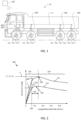
- Figure 1 illustrates an example heavy-duty vehicle 100, here in the form of a truck.
- the vehicle comprises a plurality of wheels 102, wherein at least a subset of the wheels 102 comprises a respective motion support device (MSD) 104.
- MSD motion support device
- FIG. 1 illustrates an MSD for each of the wheels 102, it should be readily understood that e.g., one pair of wheels 102 may be arranged without such an MSD 104. Also, an MSD may be arranged connected to more than one wheel, e.g., via a differential arrangement.
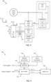
- each of the MSDs 104 is connected to a respective MSD control system or control unit 330 arranged for controlling operation of the MSD 104.
- the MSD control system 330 is preferably a decentralized motion support system 330, although centralized implementations are also possible. It is furthermore appreciated that some parts of the MSD control system may be implemented on processing circuitry remote from the vehicle, such as on a remote server 120 accessible from the vehicle via wireless link.
- each MSD control system 330 is connected to a vehicle motion management (VMM) system or function 360 of the vehicle 100 via a data bus communication arrangement 114 that can be either wired, wireless or both wired and wireless.
- VMM vehicle motion management
- control signals can be transmitted between the vehicle motion management system 360 and the MSD control system 330.
- the vehicle motion management system 360 and the MSD control system 330 will be described in further detail below with reference to Figure 3 and Figure 5 .
- the VMM system 360 as well as the MSD control system 330 may include a microprocessor, microcontroller, programmable digital signal processor or another programmable device.
- the systems may also, or instead, include an application specific integrated circuit, a programmable gate array or programmable array logic, a programmable logic device, or a digital signal processor.
- the processor may further include computer executable code that controls operation of the programmable device. Implementation aspects of the different vehicle unit processing circuits will be discussed in more detail below in connection to Figure 10 .
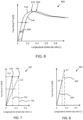
- Figure 2 is a graph showing two examples 200 of achievable tyre forces as function of longitudinal wheel slip. This type of relationship between wheel slip and generated tyre force is referred to herein as an inverse tyre model.
- the inverse tyre model can be a function as illustrated in Figure 2 , or just a piecewise linear approximation over a part of the wheel slip range, as shown in Figures 7 and 8 which will be discussed in more detail below.
- the examples in Figure 2 are for positive wheel forces, i.e., acceleration. Similar relationships exist between wheel slip and negative wheel force, i.e., braking.
- ⁇ x is bounded between -1 and 1 and quantifies how much the wheel is slipping with respect to the road surface.
- Wheel slip is, in essence, a speed difference measured between the wheel and the vehicle.
- the herein disclosed techniques can be adapted for use with any type of wheel slip definition.
- the TSM function 370 plans driving operation with a time horizon of 10 seconds or so. This time frame corresponds to, e.g., the time it takes for the vehicle 100 to negotiate a curve or the like.
- the vehicle maneuvers, planned and executed by the TSM function can be associated with acceleration profiles and curvature profiles which describe a desired target vehicle velocity in the vehicle forward direction and turning to be maintained for a given maneuver.
- the TSM function continuously requests the desired acceleration profiles a req and steering angles (or curvature profiles c req ) from the VMM function 360 which performs force allocation to meet the requests from the TSM function in a safe and robust manner.
- the VMM function 360 operates on a timescale of below one second or so and will be discussed in more detail below.
- the control unit or units can be arranged to store one or more pre-determined inverse tyre models in memory, e.g., as look-up tables or parameterized functions.
- An inverse tyre model can also be arranged to be stored in the memory as a function of the current operating condition of the wheel 310. This means that the behavior of the inverse tyre model is adjusted in dependence of the operating condition of the vehicle, which means that a more accurate model is obtained compared to one which does not account for operating condition.
- the model which is stored in memory can be determined based on experiments and trials, or based on analytical derivation, or a combination of the two. For instance, the control unit can be configured to access a set of different models which are selected depending on the current operating conditions.
- One inverse tyre model can be tailored for high load driving, where normal forces are large, another inverse tyre model can be tailored for slippery road conditions where road friction is low, and so on.
- the selection of a model to use can be based on a pre-determined set of selection rules.
- the model stored in memory can also, at least partly, be a function of operating condition.
- the model may be configured to take, e.g., normal force or road friction as input parameters, thereby obtaining the inverse tyre model in dependence of a current operating condition of the wheel 310. It is appreciated that many aspects of the operating conditions can be approximated by default operating condition parameters, while other aspects of the operating conditions can be roughly classified into a smaller number of classes.
- obtaining the inverse tyre model in dependence of a current operating condition of the wheel 310 does not necessarily mean that a large number of different models need to be stored, or a complicated analytical function which is able to account for variation in operating condition with fine granularity. Rather, it may be enough with two or three different models which are selected depending on operating condition. For instance, one model to be used when the vehicle is heavily loaded and another model to be used otherwise. In all cases, the mapping between tyre force and wheel slip changes in some way in dependence of the operating condition, which improves the precision of the mapping.
- the inverse tyre model may also be implemented at least partly as an adaptive model configured to automatically or at least semi-automatically adapt to the current operating conditions of the vehicle. This can be achieved by constantly monitoring the response of a given wheel in terms of wheel force generated in response to a given wheel slip request, and/or monitoring the response of the vehicle 100 in response to the wheel slip requests. The adaptive model can then be adjusted to more accurately model the wheel forces obtained in response to a given wheel slip request from a wheel.
- Inverse tyre models can be automatically configured from the remote server 120, e.g., as software updates, or manually by a technician performing vehicle routine servicing.
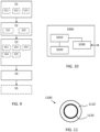
- the VMM module 360 in the example of Figure 3 has at least two different inverse tyre models configured, a default inverse tyre model 361 and a boost inverse tyre model 362, where the boost inverse tyre model 362 is associated with a higher maximum obtainable wheel slip value for one or more wheels of the vehicle compared to the default inverse tyre model.
- the boost inverse tyre model allows for a more aggressive vehicle control compared to the default inverse tyre model.
- the VMM module also comprises an inverse tyre model selection module, this module is adapted to configure the default inverse tyre model 361 as the active inverse tyre model unless a boost signal is detected.
- the inverse tyre model selection module instead configures the boost inverse tyre model 362 as the active inverse tyre model. This means that, at least temporarily, the positive propulsion wheel slip is allowed to be larger while the negative braking wheel slip is allowed to be smaller (more negative) compared to when the default inverse tyre model is selected as the active inverse tyre model.
- the VMM system and the MSD controller is at least temporarily allowed to control the wheel at a wheel slip beyond the nominal wheel slip limit of the default inverse tyre model, in order to obtain a more aggressive wheel slip behavior compared to the default behavior of the wheel.
- the boost mode allows the vehicle to approach the peak force 240, at least during a limited period of time. Consequently, a driver wanting to negotiate an up-hill road with difficult road friction conditions, would be allowed to temporarily increase wheel slip beyond the wheel slip limit of the default inverse tyre model in order to see if this provides more longitudinal wheel force or not.
- the function is similar in nature to the type of "step-down" or "kick-down" acceleration boost mode that exist in many personal cars today.
- Figure 4 shows an example of the tyre model selection function 400.
- the tyre model module 410 converts the motion request signal into a torque request with a wheel slip limit and/or into a wheel slip or wheel speed request which is sent to the MSD controller 330.
- a selection module 420 receives the boost signal, which may, e.g., be a signal indicating that the accelerator pedal or the brake pedal has been depressed beyond some threshold value.
- the selection module 420 configures the active inverse tyre model to be used in controlling the vehicle based on the status of the boost signal.
- the selection module selects parameters for parameterizing the active inverse tyre model. Some examples of such parameters which can be used to define the inverse tyre model will be discussed below in connection to Figures 6-8 . However, it is appreciated that an inverse tyre model parameter may comprise the entire tyre model also, not just a set of tyre model parameters.
- Figure 5 illustrates an example vehicle control function architecture applicable with the herein disclosed methods, where the TSM function 370 generates vehicle motion requests 375, which may comprise a desired steering angle ⁇ or an equivalent curvature c req to be followed by the vehicle, and which may also comprise desired vehicle unit accelerations areq and also other types of vehicle motion requests, which together describe a desired motion by the vehicle along a desired path at a desired velocity profile. It is understood that the motion requests can be used as base for determining or predicting a required amount of longitudinal and lateral forces which needs to be generated in order to successfully complete a maneuver.
- vehicle motion requests 375 may comprise a desired steering angle ⁇ or an equivalent curvature c req to be followed by the vehicle, and which may also comprise desired vehicle unit accelerations areq and also other types of vehicle motion requests, which together describe a desired motion by the vehicle along a desired path at a desired velocity profile.
- the motion requests can be used as base for determining or predicting a required amount of longitudinal and lateral forces which needs to be generated
- the VMM function 360 operates with a time horizon of about 1 second or so, and continuously transforms the acceleration profiles a req and curvature profiles c req from the TSM function into control commands for controlling vehicle motion functions, actuated by the different MSDs of the vehicle 100 which report back capabilities to the VMM, which in turn are used as constraints in the vehicle control.
- the VMM function 360 performs vehicle state or motion estimation 510, i.e., the VMM function 360 continuously determines a vehicle state s comprising positions, speeds, accelerations, and articulation angles of the different units in the vehicle combination by monitoring operations using various sensors arranged on the vehicle 100, often but not always in connection to the MSDs.
- the required global force vector V is input to an MSD coordination function 530 which allocates wheel forces and coordinates other MSDs such as steering and suspension.
- the MSD coordination function outputs an MSD control allocation for the i:th wheel, which may comprise any of a torque T i , a longitudinal wheel slip ⁇ i , a wheel rotational speed ⁇ i , and/or a wheel steering angle ⁇ i .
- the coordinated MSDs then together provide the desired lateral Fy and longitudinal Fx forces on the vehicle units, as well as the required moments Mz, to obtain the desired motion by the vehicle combination 100.
- vehicle unit motion By determining vehicle unit motion using, e.g., global positioning systems, vision-based sensors, wheel speed sensors, radar sensors, steering angle sensors and/or lidar sensors, and translating this vehicle unit motion into a local coordinate system of a given wheel 310 (in terms of, e.g., longitudinal and lateral velocity components), it becomes possible to accurately estimate wheel slip in real time by comparing the vehicle unit motion in the wheel reference coordinate system to data obtained from the wheel speed sensor 350 arranged in connection to the wheel 310, as discussed above.
- a local coordinate system of a given wheel 310 in terms of, e.g., longitudinal and lateral velocity components
- the VMM function 360 manages both force generation and MSD coordination, i.e., it determines what forces that are required at the vehicle units in order to fulfil the requests from the TSM function 370, for instance to accelerate the vehicle according to a requested acceleration profile requested by TSM and/or to generate a certain curvature motion by the vehicle also requested by TSM.
- the forces may comprise e.g., yaw moments Mz, longitudinal forces Fx and lateral forces Fy, as well as different types of torques to be applied at different wheels.
- the forces are determined such as to generate the vehicle behavior which is expected by the TSM function in response to the control inputs generated by the TSM function 370.
- a tyre model 540 which was discussed above in connection to Figure 2 , can be used to translate between a desired longitudinal tyre force Fx i for a given wheel i and an equivalent longitudinal wheel slip ⁇ i for the wheel.
- This tyre model is adapted based on the boost signal as discussed above, i.e., the active inverse tyre model is selected in dependence of the boost signal as a default inverse tyre model or a boost inverse tyre model which allows more wheel slip to be generated for a given wheel.
- the method comprises configuring S11 the boost inverse tyre model with a peak longitudinal wheel force 240 that corresponds to higher wheel slip value compared to the default inverse tyre model peak longitudinal wheel force.
- a peak longitudinal wheel force 240 that corresponds to higher wheel slip value compared to the default inverse tyre model peak longitudinal wheel force.
- the location of the peak wheel force is shifted to higher wheel slip values compared to the case for the default inverse tyre model.
- a system using the location of the peak force to configure, e.g., a wheel slip limit will allow a higher wheel slip to be controlled against when using the boost model compared to when using the default model, as intended.
- Figure 6 illustrates an example of this type of reconfiguration, where the default inverse tyre model is shown as the curve Fx3 with peak force location 610 and the boost inverse tyre model is shown as the curve Fx4 with peak force location 620.
- the curve Fx4 is simply a shifted version of the curve Fx3, which means that the peak location is shifted towards higher wheel slip values compared to the peak of the default inverse tyre model.
- the offset in wheel slip 630 can be configured at, say a wheel slip of 0,1 or the like. More than one offset value can also be used, for more than one boost inverse tyre model.
- the offset can also be gradually increased in response to detection of the boost signal, and then be gradually reduced back to zero after some time period.
- An optional adjustment can be added to the offset curve to make a zero generated tyre force correspond to a zero slip value, as shown by the dotted line 640 in Figure 6 .
- the method comprises configuring S12 the boost inverse tyre model with a smaller slip stiffness value compared to the default inverse tyre model.
- Figure 7 illustrates an example 700 of two inverse tyre models.
- the inverse tyre models are approximated as linear models with a rise given by the slip stiffness Cx1 and Cx2, where in this case the boost inverse tyre model has a smaller slip stiffness value Cx2 compared to the default inverse tyre model Cx1.
- Each inverse tyre model is associated with a respective wheel slip limit value 710, 720 at the assumed peak force location 730, 740.
- FIG. 8 illustrates an example of a default inverse tyre model 810 and a boost inverse tyre model 820 where the peak force location p2 of the boost inverse tyre model is higher compared to the default inverse tyre model peak location p1.
- the boost inverse tyre model allows for higher wheel slips to be controlled compared to the default inverse tyre model which will not permit a wheel slip larger than the wheel slip limit at the assumed peak location.
- the boost signal can comprise more than one level, where each level of the boost signal causes selection of a corresponding boost inverse tyre model from a plurality of boost inverse tyre models. For example, if the driver presses the gas pedal more than 70% but less than 90% a first boost inverse tyre model is selected as active inverse tyre model, and if the driver then presses the same pedal more than 90% then a second boost inverse tyre model is selected as active inverse tyre model to be used in controlling the heavy-duty vehicle.
- the boost signal S32 may also be configured to be triggered by operation of a manual trigger device.
- This manual trigger device may, e.g., be an in-cabin button or a menu selection option on a control system of the vehicle.
- a driver desiring to obtain additional wheel slip beyond the configured nominal wheel slip limit may activate the manual trigger device in order to shift the wheel slip limit to a higher magnitude value.
- This manual trigger device may of course also have more than one level, where each level corresponds to a boost inverse tyre model.
- the boost signal may of course also be arranged to be remotely triggered by operation of a remote-control trigger device.
- a remote-control tower or the like may comprise a remote-control system which implements a function to remotely activate the boost function and increase the magnitude of the configured wheel slip limit value from the nominal wheel slip limit value to a boost wheel slip limit value.
- the remote-control trigger device then implements a function which permits a given vehicle to operate at a higher wheel slip limit compared to a nominal configuration, which may be desired in some scenarios. For instance, operating at a higher wheel slip may be deemed safe if no other vehicles are nearby, and it is determined that an extra increase in wheel slip would be beneficial from a vehicle motion management performance perspective.
- the boost signal S33 may be conditioned on that the vehicle 100 is operating at a velocity below a vehicle velocity acceptance threshold. This means that no increase in wheel slip limit magnitude will be allowed to occur if the vehicle is moving too fast, which could otherwise increase the risk of the vehicle ending up in an unstable or otherwise undesired state.
- the boost signal generation S34 may furthermore be conditioned on that the vehicle 100 is operating at a yaw motion below a vehicle yaw motion acceptance threshold.
- no increase of wheel slip limit will be permitted if the vehicle is turning too much, i.e., following a path of too large curvature. It is appreciated that the condition on yaw motion may be disregarded if the vehicle is moving very slowly.
- more yaw motion may be permitted compared to if the vehicle is moving faster.
- the method may furthermore comprise determining S35 a lateral force requirement of the at least driven and/or braked wheel 102. Generation of the boost signal may then be conditioned on that the lateral force requirement is below a lateral force requirement threshold.
- the rationale for this being that only very little lateral force is possible to generate if the wheel is operating at too large longitudinal wheel slip. Hence, if there are lateral forces to be generated, it may be unwise to allow an increase of wheel slip to levels where such lateral forces cannot be generated. It is, however, appreciated that the condition on low velocity may take precedence over the condition on lateral force requirement.
- the method also comprises updating S5 the default inverse tyre model associated with the at least one driven and/or braked wheel 102 in response to detecting the boost signal.
- the VMM system may keep a record of wheel slips and corresponding estimated or measured wheel force values. For instance, some electric machines provide an output signal indicative of an applied torque in real time, which can be translated into wheel force.
- the inverse tyre model will be inaccurate for large slip values above the configured wheel slip limit, since such values never occur, unless the boost mode is used to allow them temporarily.
- FIG. 10 schematically illustrates, in terms of a number of functional units, the components of a control unit 1000 according to embodiments of the discussions herein, such as any of the MSD control system 330 or the VMM system 360.
- Processing circuitry 1010 is provided using any combination of one or more of a suitable central processing unit CPU, multiprocessor, microcontroller, digital signal processor DSP, etc., capable of executing software instructions stored in a computer program product, e.g., in the form of a storage medium 1030.
- the processing circuitry 1010 may further be provided as at least one application specific integrated circuit ASIC, or field programmable gate array FPGA.
- the processing circuitry 1010 is configured to cause the control unit 1000 to perform a set of operations, or steps, such as the methods discussed in connection to Figure 9 and generally herein.
- the storage medium 1030 may store the set of operations, and the processing circuitry 1010 may be configured to retrieve the set of operations from the storage medium 1030 to cause the control unit 1000 to perform the set of operations.
- the set of operations may be provided as a set of executable instructions.
- the processing circuitry 1010 is thereby arranged to execute methods as herein disclosed.
- the storage medium 1030 may also comprise persistent storage, which, for example, can be any single one or combination of magnetic memory, optical memory, solid state memory or even remotely mounted memory.
- the control unit 1000 may further comprise an interface 1020 for communications with at least one external device.
- the interface 1020 may comprise one or more transmitters and receivers, comprising analogue and digital components and a suitable number of ports for wireline or wireless communication.
- the processing circuitry 1010 controls the general operation of the control unit 1000, e.g., by sending data and control signals to the interface 1020 and the storage medium 1030, by receiving data and reports from the interface 1020, and by retrieving data and instructions from the storage medium 1030.
- Other components, as well as the related functionality, of the control node are omitted in order not to obscure the concepts presented herein.
- FIG. 10 illustrates an example of a control unit 1000 for controlling at least one driven and/or braked wheel 102, 310 of a heavy-duty vehicle 100.
- the control unit comprises processing circuitry 1010 arranged to configure a default inverse tyre model and a boost inverse tyre model, where each inverse tyre model represents a respective relationship between longitudinal wheel slip ⁇ and longitudinal wheel force Fx at the wheel 102, 310, where the boost inverse tyre model is associated with a higher maximum obtainable wheel slip value ⁇ lim for the wheel 102, 310 compared to the default inverse tyre model.
- the processing circuitry is also arranged to obtain a motion request a req indicative of a desired longitudinal force F x to be generated by the wheel 102, 310, select the boost inverse tyre model as active inverse tyre model in response to detecting a boost signal and selecting the default inverse tyre model as active inverse tyre model otherwise, and control the at least one driven and/or braked wheel 102, 310 in dependence of the motion request a req and based on the active inverse tyre model.
- Figure 11 illustrates a computer readable medium 1110 carrying a computer program comprising program code means 1120 for performing the methods illustrated in Figure 9 and the techniques discussed herein, when said program product is run on a computer.
- the computer readable medium and the code means may together form a computer program product 1100.
Landscapes
- Engineering & Computer Science (AREA)
- Transportation (AREA)
- Mechanical Engineering (AREA)
- Chemical & Material Sciences (AREA)
- Combustion & Propulsion (AREA)
- Automation & Control Theory (AREA)
- Physics & Mathematics (AREA)
- Microelectronics & Electronic Packaging (AREA)
- Fluid Mechanics (AREA)
- Regulating Braking Force (AREA)
- Control Of Driving Devices And Active Controlling Of Vehicle (AREA)
- Mathematical Physics (AREA)
Claims (15)
- Computerimplementiertes Verfahren zum Steuern von mindestens einem angetriebenen und/oder gebremsten Rad (102, 310) eines Schwerlastfahrzeugs (100), das Verfahren umfassend:Konfigurieren (S1) eines standardmäßigen inversen Reifenmodells und eines verstärkten inversen Reifenmodells, wobei jedes inverse Reifenmodell eine entsprechende Beziehung zwischen dem Radschlupf in Längsrichtung (λ) und der Radkraft in Längsrichtung (Fx) an dem Rad (102, 310) darstellt, wobei das verstärkte inverse Reifenmodell mit einem höheren maximal erreichbaren Radschlupfwert (λlim) für das Rad (102, 310) im Vergleich zu dem standardmäßigen inversen Reifenmodell verbunden ist,Erhalten (S2) einer Bewegungsanforderung (areq), die eine gewünschte Kraft in Längsrichtung (Fx) angibt, die durch das Rad (102, 310) erzeugt werden soll,Auswählen (S3) des verstärkten inversen Reifenmodells als aktives inverses Reifenmodell undSteuern (S4) des mindestens einen angetriebenen und/oder gebremsten Rades (102, 310) in Abhängigkeit von der Bewegungsanforderung (areq) und basierend auf dem aktiven inversen Reifenmodell,dadurch gekennzeichnet, dassdas verstärkte inverse Reifenmodell als aktives inverses Reifenmodell in Reaktion auf das Erkennen eines Verstärkungssignals (550) ausgewählt wird und andernfalls das standardmäßige inverse Reifenmodell als aktives inverses Reifenmodell ausgewählt wird.
- Verfahren nach Anspruch 1, umfassend das Konfigurieren (S11) des verstärkenden inversen Reifenmodells mit einer Spitzenkraft in Längsrichtung (240), die einem höheren Radschlupfwert im Vergleich zur Spitzenkraft in Längsrichtung des standardmäßigen inversen Reifenmodells entspricht.
- Verfahren nach Anspruch 1 oder 2, umfassend das Konfigurieren (S12) des verstärkten inversen Reifenmodells mit einem kleineren Schlupfsteifigkeitswert (260, 270) im Vergleich zum standardmäßigen inversen Reifenmodell.
- Verfahren nach einem der vorhergehenden Ansprüche, umfassend das Konfigurieren (S13) des verstärkten inversen Reifenmodells mit einem höheren Radschlupfgrenzwert (230) im Vergleich zu dem standardmäßigen inversen Reifenmodell.
- Verfahren nach einem der vorhergehenden Ansprüche, umfassend das Erhalten (S21) der Bewegungsanforderung (areq) als Funktion einer Gaspedalstellung oder einer Bremspedalstellung des Schwerlastfahrzeugs (100).
- Verfahren nach einem der vorhergehenden Ansprüche, umfassend das Erhalten (S22) der Bewegungsanforderung (areq) von einer Koordinierungsfunktion (530) einer Bewegungsunterstützungsvorrichtung (MSD) eines Fahrzeugbewegungsmanagementsystems (VMM), das in dem Schwerlastfahrzeug (100) enthalten ist, oder von einer autonomen oder halbautonomen Antriebsfunktion, die in dem Fahrzeug (100) enthalten ist.
- Verfahren nach einem der vorhergehenden Ansprüche, wobei das Verstärkungssignal (S31) durch eine Gaspedalstellung oder eine Bremspedalstellung ausgelöst wird, die einen vorgegebenen Schwellenwert überschreitet.
- Verfahren nach einem der vorhergehenden Ansprüche, wobei das Verstärkungssignal (S32) so beschaffen ist, dass es durch Betätigung einer Auslösevorrichtung manuell ausgelöst wird.
- Verfahren nach einem der vorhergehenden Ansprüche, wobei das Verstärkungssignal (S33) davon abhängt, dass das Fahrzeug (100) mit einer Geschwindigkeit unterhalb eines Akzeptanzschwellenwerts für die Fahrzeuggeschwindigkeit fährt.
- Verfahren nach einem der vorhergehenden Ansprüche, wobei das Verstärkungssignal (S34) davon abhängig ist, dass das Fahrzeug (100) mit einer Gierbewegung unterhalb eines Akzeptanzschwellenwerts für die Fahrzeuggierbewegung fährt.
- Verfahren nach einem der vorhergehenden Ansprüche, umfassend das Bestimmen (S35) einer seitlichen Kraftanforderung des mindestens angetriebenen und/oder gebremsten Rades (102), wobei das Verstärkungssignal davon abhängig ist, dass die seitliche Kraftanforderung unter einem Schwellenwert für die seitliche Kraftanforderung liegt.
- Verfahren nach einem der vorhergehenden Ansprüche, umfassend das Aktualisieren (S5) des standardmäßigen inversen Reifenmodells als Reaktion auf das Erfassen des Verstärkungssignals (550).
- Computerprogramm, umfassend Anweisungen, die den Computer veranlassen, die Schritte
nach einem der Ansprüche 1 bis 12 auszuführen, wenn das Programm auf einem Computer ausgeführt wird. - Steuergerät (300, 400, 500, 1000) zum Steuern von mindestens einem angetriebenen und/oder gebremsten Rad (102, 310) eines Schwerlastfahrzeugs (100), wobei das Steuergerät eine Verarbeitungsschaltung (1010) umfasst, die so angeordnet ist, dass esein standardmäßiges inverses Reifenmodell und ein verstärktes inverses Reifenmodell konfiguriert, wobei jedes inverse Reifenmodell eine entsprechende Beziehung zwischen dem Radschlupf in Längsrichtung (λ) und der Radkraft in Längsrichtung (Fx) an dem Rad (102, 310) darstellt, wobei das verstärkte inverse Reifenmodell mit einem höheren maximal erreichbaren Radschlupfwert (λlim) für das Rad (102, 310) im Vergleich zu dem standardmäßigen inversen Reifenmodell verbunden ist,eine Bewegungsanforderung (areq) erhält, die eine gewünschte Kraft in Längsrichtung (Fx) angibt, die von dem Rad (102, 310) erzeugt werden soll,das verstärkte inversen Reifenmodell als aktives inverses Reifenmodell auswählt unddas mindestens eine angetriebene und/oder gebremste Rad (102, 310) in Abhängigkeit von der Bewegungsanforderung (areq) und basierend auf dem aktiven inversen Reifenmodell steuert,dadurch gekennzeichnet, dassdie Verarbeitungsschaltung so angeordnet ist, dass sie das verstärkte inverse Reifenmodell als aktives inverses Reifenmodell in Reaktion auf das Erkennen eines Verstärkungssignals ausgewählt und andernfalls das standardmäßige inverse Reifenmodell als aktives inverses Reifenmodell auswählt.
- Schwerlastfahrzeug (100), umfassend ein Steuergerät nach Anspruch 14.
Applications Claiming Priority (2)
| Application Number | Priority Date | Filing Date | Title |
|---|---|---|---|
| EP21203148.8A EP4166368B1 (de) | 2021-10-18 | 2021-10-18 | Radschlupfverstärkungsfunktion für ein schwerlastfahrzeug |
| PCT/EP2022/052223 WO2023066527A1 (en) | 2021-10-18 | 2022-01-31 | Inverse tyre model boost function for a heavy-duty vehicle |
Publications (3)
| Publication Number | Publication Date |
|---|---|
| EP4419366A1 EP4419366A1 (de) | 2024-08-28 |
| EP4419366B1 true EP4419366B1 (de) | 2025-07-09 |
| EP4419366C0 EP4419366C0 (de) | 2025-07-09 |
Family
ID=78500382
Family Applications (2)
| Application Number | Title | Priority Date | Filing Date |
|---|---|---|---|
| EP21203148.8A Active EP4166368B1 (de) | 2021-10-18 | 2021-10-18 | Radschlupfverstärkungsfunktion für ein schwerlastfahrzeug |
| EP22702474.2A Active EP4419366B1 (de) | 2021-10-18 | 2022-01-31 | Inverse reifenmodellverstärkungsfunktion für ein schwerlastfahrzeug |
Family Applications Before (1)
| Application Number | Title | Priority Date | Filing Date |
|---|---|---|---|
| EP21203148.8A Active EP4166368B1 (de) | 2021-10-18 | 2021-10-18 | Radschlupfverstärkungsfunktion für ein schwerlastfahrzeug |
Country Status (6)
| Country | Link |
|---|---|
| US (2) | US20250242812A1 (de) |
| EP (2) | EP4166368B1 (de) |
| JP (2) | JP2024541857A (de) |
| KR (2) | KR20240093520A (de) |
| CN (2) | CN118119522A (de) |
| WO (1) | WO2023066527A1 (de) |
Families Citing this family (4)
| Publication number | Priority date | Publication date | Assignee | Title |
|---|---|---|---|---|
| FR3087387B1 (fr) * | 2018-10-19 | 2021-10-08 | Michelin & Cie | Procede de simulation de l'evolution temporelle d'un systeme physique en temps reel |
| JP2024531795A (ja) * | 2021-09-21 | 2024-08-29 | ボルボトラックコーポレーション | 大型の車両向けの車輪スリップに基づいた運動制御 |
| WO2025103566A1 (en) * | 2023-11-13 | 2025-05-22 | Volvo Truck Corporation | Road slope based actuator control for open differentials |
| WO2025103589A1 (en) * | 2023-11-15 | 2025-05-22 | Volvo Truck Corporation | Wheel slip control |
Family Cites Families (20)
| Publication number | Priority date | Publication date | Assignee | Title |
|---|---|---|---|---|
| JP3296050B2 (ja) * | 1993-10-07 | 2002-06-24 | 日産自動車株式会社 | アンチスキッド制御装置 |
| US5530617A (en) * | 1994-05-12 | 1996-06-25 | Simmonds Precision Engine Systems, Inc. | Exciter circuit with oscillatory discharge and solid state switchiing device |
| DE19527840B4 (de) * | 1995-07-28 | 2004-09-16 | Siemens Ag | Schaltungsanordnung zum Steuern des zwischen den Antriebsrädern eines Kraftfahrzeugs und der Fahrbahn übertragenen Drehmoments |
| JPH09290751A (ja) * | 1996-04-26 | 1997-11-11 | Toyota Motor Corp | 制動力制御装置 |
| JP3748334B2 (ja) * | 1997-10-15 | 2006-02-22 | 日野自動車株式会社 | 車両の姿勢制御装置 |
| DE19919675C2 (de) * | 1999-04-30 | 2003-04-10 | Daimler Chrysler Ag | Steuerungssystem für ein Fahrzeug |
| JP4090726B2 (ja) * | 2001-11-26 | 2008-05-28 | 横浜ゴム株式会社 | ブレーキ制御装置、ブレーキ制御方法および記録媒体 |
| US8244445B2 (en) | 2007-10-30 | 2012-08-14 | Ford Global Technologies, Llc | Stuck vehicle with time and pedal related traction control |
| KR101360038B1 (ko) * | 2011-07-28 | 2014-02-07 | 현대자동차주식회사 | 인휠 모터를 이용한 차량 제어 방법 |
| GB201210282D0 (en) * | 2012-06-11 | 2012-07-25 | Jaguar Cars | Vehicle and method of control thereof |
| DE102015201612B4 (de) * | 2014-05-16 | 2022-05-05 | Ford Global Technologies, Llc | Verbesserte Radschlupfsteuerung |
| CN109415041B (zh) | 2016-06-15 | 2022-02-18 | 沃尔沃卡车集团 | 用于车辆的车轮控制器 |
| EP3398825B1 (de) * | 2017-05-03 | 2020-03-11 | Volvo Car Corporation | Verfahren und system zur berechnung einer fahrbahnreibungsschätzung |
| SE542262C2 (en) * | 2017-07-24 | 2020-03-31 | Scania Cv Ab | A method for controlling a powertrain, a control arrangement for controlling a powertrain, a powertrain, a vehicle, a computer program and a computer-readable medium |
| JP6748619B2 (ja) * | 2017-09-20 | 2020-09-02 | 日立オートモティブシステムズ株式会社 | 車両制御装置、車両制御方法および車両制御システム |
| US11097739B2 (en) * | 2018-02-22 | 2021-08-24 | GM Global Technology Operations LLC | Method to estimate tire-road friction, prior to safety systems engagement |
| JP7010152B2 (ja) * | 2018-06-14 | 2022-02-10 | トヨタ自動車株式会社 | 車両のブレーキ制御装置 |
| JP2021044975A (ja) * | 2019-09-12 | 2021-03-18 | トヨタ自動車株式会社 | 車両の制御装置 |
| CN114945496B (zh) * | 2020-01-15 | 2025-07-11 | 沃尔沃卡车集团 | 基于具有速度极限的扭矩请求的车辆运动管理 |
| JP7411102B2 (ja) | 2020-01-15 | 2024-01-10 | ボルボトラックコーポレーション | 大型車両を動作させる方法 |
-
2021
- 2021-10-18 EP EP21203148.8A patent/EP4166368B1/de active Active
-
2022
- 2022-01-31 CN CN202280069850.XA patent/CN118119522A/zh active Pending
- 2022-01-31 WO PCT/EP2022/052223 patent/WO2023066527A1/en not_active Ceased
- 2022-01-31 JP JP2024522678A patent/JP2024541857A/ja active Pending
- 2022-01-31 US US18/702,210 patent/US20250242812A1/en active Pending
- 2022-01-31 EP EP22702474.2A patent/EP4419366B1/de active Active
- 2022-01-31 KR KR1020247014184A patent/KR20240093520A/ko active Pending
- 2022-09-28 US US17/936,131 patent/US12522067B2/en active Active
- 2022-09-30 CN CN202211206544.4A patent/CN115991201A/zh active Pending
- 2022-10-03 JP JP2022159698A patent/JP2023060823A/ja active Pending
- 2022-10-04 KR KR1020220126119A patent/KR20230055359A/ko active Pending
Also Published As
| Publication number | Publication date |
|---|---|
| KR20230055359A (ko) | 2023-04-25 |
| JP2023060823A (ja) | 2023-04-28 |
| EP4419366A1 (de) | 2024-08-28 |
| EP4419366C0 (de) | 2025-07-09 |
| EP4166368B1 (de) | 2024-03-27 |
| US20230120062A1 (en) | 2023-04-20 |
| EP4166368C0 (de) | 2024-03-27 |
| US20250242812A1 (en) | 2025-07-31 |
| WO2023066527A1 (en) | 2023-04-27 |
| CN115991201A (zh) | 2023-04-21 |
| EP4166368A1 (de) | 2023-04-19 |
| KR20240093520A (ko) | 2024-06-24 |
| JP2024541857A (ja) | 2024-11-13 |
| CN118119522A (zh) | 2024-05-31 |
| US12522067B2 (en) | 2026-01-13 |
Similar Documents
| Publication | Publication Date | Title |
|---|---|---|
| US12304447B2 (en) | Wheel slip based vehicle motion management for heavy duty vehicles | |
| EP4419366B1 (de) | Inverse reifenmodellverstärkungsfunktion für ein schwerlastfahrzeug | |
| US20230047444A1 (en) | Vehicle motion management based on torque request with speed limit | |
| EP4219252B1 (de) | Verfahren zur steuerung eines schwerlastfahrzeugs | |
| US20250289320A1 (en) | Vehicle motion management system and motion support device control system | |
| US12337813B2 (en) | Vehicle motion management with a redundant wheel control safety net function | |
| US20250178575A1 (en) | Selective free-rolling of wheels for robust vehicle speed over ground determination | |
| US20250178614A1 (en) | Robust vehicle speed over ground estimation using wheel speed sensors and inertial measurement units | |
| WO2023169700A1 (en) | Selective free-rolling of wheels for robust vehicle speed over ground determination | |
| EP4482718B1 (de) | Systeme zur bestimmung der fahrzeuggeschwindigkeit über dem boden | |
| KR20240105392A (ko) | 중장비 차량의 가속 및 감속을 위한 휠 슬립 기반 제어 |
Legal Events
| Date | Code | Title | Description |
|---|---|---|---|
| STAA | Information on the status of an ep patent application or granted ep patent |
Free format text: STATUS: UNKNOWN |
|
| STAA | Information on the status of an ep patent application or granted ep patent |
Free format text: STATUS: THE INTERNATIONAL PUBLICATION HAS BEEN MADE |
|
| PUAI | Public reference made under article 153(3) epc to a published international application that has entered the european phase |
Free format text: ORIGINAL CODE: 0009012 |
|
| STAA | Information on the status of an ep patent application or granted ep patent |
Free format text: STATUS: REQUEST FOR EXAMINATION WAS MADE |
|
| 17P | Request for examination filed |
Effective date: 20240417 |
|
| AK | Designated contracting states |
Kind code of ref document: A1 Designated state(s): AL AT BE BG CH CY CZ DE DK EE ES FI FR GB GR HR HU IE IS IT LI LT LU LV MC MK MT NL NO PL PT RO RS SE SI SK SM TR |
|
| DAV | Request for validation of the european patent (deleted) | ||
| DAX | Request for extension of the european patent (deleted) | ||
| REG | Reference to a national code |
Ref country code: DE Ref legal event code: R079 Free format text: PREVIOUS MAIN CLASS: B60K0028160000 Ipc: B60W0030180000 Ref document number: 602022017281 Country of ref document: DE |
|
| GRAP | Despatch of communication of intention to grant a patent |
Free format text: ORIGINAL CODE: EPIDOSNIGR1 |
|
| STAA | Information on the status of an ep patent application or granted ep patent |
Free format text: STATUS: GRANT OF PATENT IS INTENDED |
|
| RIC1 | Information provided on ipc code assigned before grant |
Ipc: B60W 50/00 20060101ALI20250212BHEP Ipc: B60K 28/16 20060101ALI20250212BHEP Ipc: B60W 30/18 20120101AFI20250212BHEP |
|
| INTG | Intention to grant announced |
Effective date: 20250219 |
|
| GRAS | Grant fee paid |
Free format text: ORIGINAL CODE: EPIDOSNIGR3 |
|
| GRAA | (expected) grant |
Free format text: ORIGINAL CODE: 0009210 |
|
| STAA | Information on the status of an ep patent application or granted ep patent |
Free format text: STATUS: THE PATENT HAS BEEN GRANTED |
|
| AK | Designated contracting states |
Kind code of ref document: B1 Designated state(s): AL AT BE BG CH CY CZ DE DK EE ES FI FR GB GR HR HU IE IS IT LI LT LU LV MC MK MT NL NO PL PT RO RS SE SI SK SM TR |
|
| REG | Reference to a national code |
Ref country code: GB Ref legal event code: FG4D |
|
| REG | Reference to a national code |
Ref country code: CH Ref legal event code: EP |
|
| REG | Reference to a national code |
Ref country code: IE Ref legal event code: FG4D |
|
| U01 | Request for unitary effect filed |
Effective date: 20250709 |
|
| U07 | Unitary effect registered |
Designated state(s): AT BE BG DE DK EE FI FR IT LT LU LV MT NL PT RO SE SI Effective date: 20250715 |
|
| PG25 | Lapsed in a contracting state [announced via postgrant information from national office to epo] |
Ref country code: IS Free format text: LAPSE BECAUSE OF FAILURE TO SUBMIT A TRANSLATION OF THE DESCRIPTION OR TO PAY THE FEE WITHIN THE PRESCRIBED TIME-LIMIT Effective date: 20251109 |
|
| PG25 | Lapsed in a contracting state [announced via postgrant information from national office to epo] |
Ref country code: NO Free format text: LAPSE BECAUSE OF FAILURE TO SUBMIT A TRANSLATION OF THE DESCRIPTION OR TO PAY THE FEE WITHIN THE PRESCRIBED TIME-LIMIT Effective date: 20251009 |
|
| PG25 | Lapsed in a contracting state [announced via postgrant information from national office to epo] |
Ref country code: HR Free format text: LAPSE BECAUSE OF FAILURE TO SUBMIT A TRANSLATION OF THE DESCRIPTION OR TO PAY THE FEE WITHIN THE PRESCRIBED TIME-LIMIT Effective date: 20250709 |