EP4419040B1 - Lastausgleichsarm für stützsystem für medizinische vorrichtungen - Google Patents
Lastausgleichsarm für stützsystem für medizinische vorrichtungen Download PDFInfo
- Publication number
- EP4419040B1 EP4419040B1 EP22800930.4A EP22800930A EP4419040B1 EP 4419040 B1 EP4419040 B1 EP 4419040B1 EP 22800930 A EP22800930 A EP 22800930A EP 4419040 B1 EP4419040 B1 EP 4419040B1
- Authority
- EP
- European Patent Office
- Prior art keywords
- spring
- load balancing
- arm
- support arm
- distal end
- Prior art date
- Legal status (The legal status is an assumption and is not a legal conclusion. Google has not performed a legal analysis and makes no representation as to the accuracy of the status listed.)
- Active
Links
Images


Classifications
-
- A—HUMAN NECESSITIES
- A61—MEDICAL OR VETERINARY SCIENCE; HYGIENE
- A61B—DIAGNOSIS; SURGERY; IDENTIFICATION
- A61B90/00—Instruments, implements or accessories specially adapted for surgery or diagnosis and not covered by any of the groups A61B1/00 - A61B50/00, e.g. for luxation treatment or for protecting wound edges
- A61B90/50—Supports for surgical instruments, e.g. articulated arms
-
- F—MECHANICAL ENGINEERING; LIGHTING; HEATING; WEAPONS; BLASTING
- F16—ENGINEERING ELEMENTS AND UNITS; GENERAL MEASURES FOR PRODUCING AND MAINTAINING EFFECTIVE FUNCTIONING OF MACHINES OR INSTALLATIONS; THERMAL INSULATION IN GENERAL
- F16M—FRAMES, CASINGS OR BEDS OF ENGINES, MACHINES OR APPARATUS, NOT SPECIFIC TO ENGINES, MACHINES OR APPARATUS PROVIDED FOR ELSEWHERE; STANDS; SUPPORTS
- F16M13/00—Other supports for positioning apparatus or articles; Means for steadying hand-held apparatus or articles
- F16M13/02—Other supports for positioning apparatus or articles; Means for steadying hand-held apparatus or articles for supporting on, or attaching to, an object, e.g. tree, gate, window-frame, cycle
- F16M13/027—Ceiling supports
-
- A—HUMAN NECESSITIES
- A61—MEDICAL OR VETERINARY SCIENCE; HYGIENE
- A61B—DIAGNOSIS; SURGERY; IDENTIFICATION
- A61B90/00—Instruments, implements or accessories specially adapted for surgery or diagnosis and not covered by any of the groups A61B1/00 - A61B50/00, e.g. for luxation treatment or for protecting wound edges
- A61B90/50—Supports for surgical instruments, e.g. articulated arms
- A61B2090/5025—Supports for surgical instruments, e.g. articulated arms with a counter-balancing mechanism
-
- F—MECHANICAL ENGINEERING; LIGHTING; HEATING; WEAPONS; BLASTING
- F16—ENGINEERING ELEMENTS AND UNITS; GENERAL MEASURES FOR PRODUCING AND MAINTAINING EFFECTIVE FUNCTIONING OF MACHINES OR INSTALLATIONS; THERMAL INSULATION IN GENERAL
- F16M—FRAMES, CASINGS OR BEDS OF ENGINES, MACHINES OR APPARATUS, NOT SPECIFIC TO ENGINES, MACHINES OR APPARATUS PROVIDED FOR ELSEWHERE; STANDS; SUPPORTS
- F16M2200/00—Details of stands or supports
- F16M2200/04—Balancing means
Definitions
- This application relates generally to a load balancing arm for a medical device support system or carry system for use in, for example, a hospital examination room, a clinic, a surgery room or an emergency room, and more particularly to a load balancing arm that improves force transmission and increases load balancing capacity.
- Medical device support systems are used in health treatment settings such as hospital examination rooms, clinics, surgery rooms and emergency rooms. These systems may suspend or support any variety of medical devices or components including surgical lights, supply consoles, patient monitors, camera detector heads, medical instruments, ventilator systems, suction devices, among others.
- the support systems typically include a central shaft or support column that is suspended from the ceiling or mounted to a wall, one or more generally horizontal extension arms mounted for rotational movement about the shaft, and one or more load balancing arms, also known as counterbalancing arms, that enable positioning of a medical device to a proper orientation relative to for example a patient operating table and healthcare professionals in the operating room.
- the extension arms and load balancing arms each include a support arm structure or housing, or more generally a support arm.
- a load balancing arm may have insufficient capacity to adequately balance a load, whether due to the arm's spring lacking a sufficient counterbalancing effect or due to the arm's inability to otherwise provide a stable and natural handling for the operator.
- Simply increasing the spring force of the arm's spring may not be practicable as it may require increasing the spring constant and thus increasing the cross sectional area of the spring and consequently the cross sectional area of the load balancing arm.
- US4447031 and US2020/246110 disclose known load balancing arms.
- the application relates to a load balancing arm for a medical device support system, in which a link connects at its proximal end to a link bearing element and at its distal end to a distal end of a first spring and a proximal end of a second spring, where both of the springs are within a cavity of the load balancing arm and contribute to the counterbalancing biasing forces of the load balancing arm.
- a load balancing arm configured in this way improves the force transmission and increases the load bearing capacity of the load balancing arm with minimal or no corresponding increase in the size of the load balancing arm.
- a load balancing arm for a medical device support system includes a proximal hub including a main bearing element defining a main pivot axis; a link bearing element defining a link pivot axis; a support arm having a proximal end and a distal end, wherein the distal end is configured to support a medical device load and the proximal end is pivotably mounted to the main bearing element for pivotable movement about the main pivot axis; a first spring extending within a cavity of the support arm and mounted to exert a biasing force between the main pivot axis and a distal end of the first spring; a second spring extending within the cavity of the support arm and mounted to exert a biasing force between a proximal end of the second spring and a wall at the distal end of the support arm; and, at least one link having a proximal end pivotably mounted to the link bearing element for pivotable movement about the link pivot axis, and a distal end pivotably mounted
- Embodiments of the invention may include one or more of the following additional features separately or in combination.
- the first spring and the second spring may be connected functionally in series.
- the first and second springs may be oriented along an axis that extends radially from and perpendicular to the main pivot axis.
- the first spring may be configured to expand and contract along a first axis and the second spring may be configured to expand and contract along a second axis, and the first and second axes may coincide with one another.
- the biasing force of the first spring may be configured to bias the distal end of the at least one link toward the main pivot axis at the proximal end of the support arm and the biasing force of the second spring may be configured to bias the distal end of the at least one link toward the wall at the distal end of the support arm.
- the link pivot axis may be axially spaced from the main pivot axis.
- the link bearing element may be an adjustable bearing element, and the link pivot axis may be adjustable axially relative to the main pivot axis.
- the first spring may be a compression spring and the second spring may be a tension spring.
- the load balancing arm may further include a carriage slide that is slidable relative to the support arm, and the distal end of the link may be pivotably mounted to the distal end of the first spring and the proximal end of the second spring via the carriage slide.
- the proximal end of the second spring and the distal end of the first spring may be connected to axially opposite ends of the carriage slide.
- the proximal end of the second spring, the carriage slide, and the distal end of the first spring may be configured to move together in unison as the carriage slide moves relative to the support arm.
- the carriage slide may be slidable within at least one groove in the support arm.
- the groove may be oriented along an axis that extends radially from and perpendicular to the main pivot axis.
- the wall may be an internal wall that is supported by and projects inward from a perimeter wall of the support arm that surrounds the first and second springs.
- the first and second springs may be gas springs having a cylinder and a rod, and the rod of the first spring and the cylinder of the second spring may be pivotably mounted to the distal end of the at least one link.
- the at least one link may comprise a pair of links that straddle the first spring on laterally opposite sides of the first spring.
- the support arm may include an intermediate portion between the proximal end and distal end of the support arm, and the intermediate portion may have a relatively narrower height span than the proximal end of the support arm, and the at least one link may have at least one bend that corresponds to the difference in height span between the intermediate portion and the proximal end of the support arm.
- the support arm may have an angle of rotation about the main pivot axis of about 30 degrees upward from horizontal to about 85 degrees downward from horizontal.
- the load balancing arm may further include a parallel link that is pivotably connected at its proximal end to a pin supported by the proximal hub and at its distal end to a pin supported by a distal hub pivotably connected to the distal end of the support arm.
- the parallel link may include a pair of laterally spaced side walls that straddle a vertically lower portion of the first and second springs on laterally opposite sides of the first and second springs.
- the parallel link may include a pair of laterally spaced side walls that straddle the at least one link on laterally opposite sides of the at least one link over at least a portion of a pivotable range of the load adjustment arm.
- Fig. 1 shows a medical device support system 10.
- the medical device support system 10 includes a central shaft or support column 14 that is suspended from the ceiling, and three generally horizontal extension arms 16 mounted to the shaft 14 for rotational movement about the shaft 14.
- the central shaft 14 could be mounted to a wall or stand rather than the ceiling.
- Three load balancing arms 18, which are also referred to as counterbalancing arms, are mounted to the respective extension arms 16.
- the extension arms 16 and load balancing arms 18 each include a support arm structure or housing, or more generally a support arm.
- a proximal hub 22 of the load balancing arm 18 includes a support structure 24, for example the illustrative drop tube 24, that is rotatably connectable to a receptacle at the distal end 30 of the extension arm 16.
- the distal end of each load balancing arm 18 is configured with a suitable support hub 34 to support a medical device load 36.
- the medical device load 36 may include a surgical light as shown, or a supply console, a patient monitor, a camera detector head, a medical instrument, a ventilator system, a suction device, among others.
- a control console if provided, may provide controls for navigation of a medical instrument that is either coupled to or remote from the load balancing arm 18.
- the load balancing arm 18 enables positioning of the medical device 36 to a proper orientation relative to for example a patient operating table and healthcare professionals in the operating room.
- the load balancing arm 100 includes a proximal hub 104, an adjustable bearing element 108, a support arm 110, a spring 116, and one or more links, two such links 124, 126 in the illustrative embodiment, as shown in Fig. 3 and 12 .
- the proximal hub 104 may include a support structure 24 such as the drop tube 24 (see Fig. 1 ).
- the proximal hub 104 includes a main bearing element 130 that defines a main pivot axis 132.
- the adjustable bearing element 108 defines an adjustable pivot axis 142 that is adjustable relative to the main pivot axis 132.
- the support arm 110 has a proximal end 150 and a distal end 152.
- the distal end 152 is configured to support a medical device load 36 (see Fig. 1 ) and the proximal end 150 is pivotably mounted to the main bearing element 130 for pivotable movement about the main pivot axis 132. Pivotable movement about the main pivot axis 132 raises and lowers the height of the medical device load 36 at the distal end 152.
- the spring 116 extends within a cavity 154 of the support arm 110 and is mounted to exert a biasing force between the main pivot axis 132 and a distal end 158 of the spring 116.
- the links 124, 126 each have a proximal end 160 and a distal end 162.
- the proximal end 160 is pivotably mounted to the adjustable bearing element 108 for pivotable movement about the adjustable pivot axis 142.
- the distal ends 162 of the links 124, 126 are pivotably mounted to the distal end 158 of the spring 116 such that the biasing force exerted by the spring 116 is transmitted through the links 124, 126 to the adjustable bearing element 108 thereby to generate a moment about the main pivot axis 132 of the proximal hub 104 that counters a moment generated by the medical device load 36 at the distal end 152 of the support arm 110, thereby balancing the medical device load 36.
- the links 124, 126 connect at their proximal ends 160 to an adjustment bearing element 108 and at their distal ends 162 to the distal end 158 of the spring 116.
- the attachment at the distal end 158 of the spring 116 allows for a relatively longer link than if connected to the proximal end of the spring 116. This allows for a better force transmission and less spring travel resulting in a more balanced load balancing arm 100 throughout the pivotable range of travel of the arm 100.
- Figs. 2-6 and 15-20 show greater detail of the support arm 110, the proximal hub 104, and the interface between the support arm 110 and proximal hub 104.
- the proximal end 150 of the support arm 110 has a relatively smaller width than the proximal hub 104 and fits within the proximal hub 104.
- the proximal end 150 of the support arm 110 includes a pair of vertically oriented laterally spaced protrusions or tongue portions 170 and a circular portion 178 substantially surrounding the tongue portions 170. As shown in Figs.
- the proximal hub 104 includes a mounting surface 184 for mounting the proximal hub 104 and thus the load balancing arm 100 to, for example, the distal end of an extension arm 16.
- the proximal hub 104 includes a pair of vertically oriented side walls 188 alongside which the tongue portions 170 of the support arm 110 slide during adjusting of the support arm 110.
- the side walls 188 have a circular shape that corresponds in diameter to the circular portion 178 of the proximal end 150 of the support arm 110.
- the proximal hub 104 also includes a load adjustment base 196 that extends width-wise between the pair of vertically oriented side walls 188 and that, as shown in Figs. 15-20 , extends vertically downward from a location just below the vertically uppermost portion of the circular portion 178 of the proximal end 150 of the support arm 110 downward approximately three fourths the distance across the circular portion 178. Details of one example of the load adjustment base 196 are shown in Figs. 9 , 10 , 12-14 and 18-20 . As shown in Fig. 10 , the load adjustment base 196 may be fastened to the side walls 188 by fasteners 198. As shown in Figs.
- the load adjustment base 196 has a pair of laterally spaced flanges 204 that are recessed inward from the outer width of the load adjustment base 196. Referring to Fig. 9 , the recessed flanges 204 form respective gaps 210 with the side walls 188 within which the tongue portions 170 of the support arm 110 are received. As shown in Figs. 9 , 12 and 18-20 , the tongue portions 170 of the proximal end 150 of the support arm 110 have through holes 236 and the main bearing element 130 of the proximal hub 104 includes a pair of laterally spaced pins 240. The central axis of these pins 240 defines or coincides with the main pivot axis 132. The through holes 236 receive the pins 240 thereby to pivotably mount the proximal end 150 of the support arm 110 to the main bearing element 130 of the proximal hub 104 for pivotable movement of the support arm 110 about the main pivot axis 132.
- bushings 244 are provided on the pins 240 to promote smooth pivotable operation and serviceability. As shown in Figs. 8 , 10 and 12 , the pins 240 are fixedly connected, for example by welding, to a retainer plate 252, which, in turn, is fastened to the side walls 188 of the proximal hub 104 by fasteners 258.
- a load adjustment screw 280 is rotatably mounted in a bottom wall 284 of the load adjustment base 196.
- the load adjustment screw 280 is fixed in a vertical orientation in the proximal hub 104 and rotates about its own central axis 290.
- the axis 290 of the load adjustment screw 280 is parallel to an axis 296 of rotation of the load balancing arm 100 extending centrally through the support structure 24 and perpendicular to horizontal. As shown in Figs.
- the adjustable bearing element 108 includes a load adjustment nut 310 that threadably engages the load adjustment screw 280 to adjust the adjustable pivot axis 142 relative to the main pivot axis 132.
- the load adjustment nut 310 moves in the vertical direction as the load adjustment screw 280 is rotated, which vertical movement adjusts the adjustable pivot axis 142 relative to the main pivot axis 132.
- the adjustable bearing element 108 includes a pin 324 that is carried by the load adjustment nut 310.
- the central axis of the pin 324 defines or coincides with the adjustable pivot axis 142.
- the proximal ends 160 of the links 124, 126 are pivotably mounted to the pin 324 at respective opposite ends of the pin 324.
- the adjustable pivot axis 142 is adjustable relative to the main pivot axis 132 over a range of adjustment 330, defined in the illustrative embodiment by the uppermost and lowermost vertical position of the load adjustment nut 310.
- the vertical movement of the load adjustment nut 310 adjusts the load capacity of the load balancing arm 100.
- the distance between the adjustable pivot axis 142 of the pin 324 and the main pivot axis 132 of the proximal hub 104 provides the mechanical advantage, or moment, that allows the load balancing arm 100 to balance a medical device load 36 at the distal end 152 of the arm 100.
- the laterally spaced pins 240 split the main pivot axis 132 thereby enabling the adjustable bearing element 108 to be moved vertically across the main pivot axis 132 into a position between the laterally spaced pins 240. Accordingly, the adjustable bearing element 108 and the proximal ends 160 of the respective pair of links 124, 126 are movable between the pair of pins 240 over a portion of the range of adjustment 330. As will be appreciated, this provides greater adjustment range in the proximal ends 160 of the links 124, 126 pivotably mounted to the pin 324 of the adjustable bearing element 108 than if the pins 240 were a single pin member and the main pivot axis 132 was not split.
- the split main pivot axis 132 i.e. laterally spaced pins 240, also enables the proximal ends 160 of the links 124, 126 to move between the pins 240 for example when the load balancing arm 100 is pivoted to lower positions.
- the adjustable pivot axis 142 of the adjustable bearing element 108 is horizontally offset from the main pivot axis 132 of the main bearing element 130 in a direction toward the portion of the proximal hub 104 that includes the support structure 24, in the illustrative embodiment toward the axis 296 of rotation of the load balancing arm 100 extending centrally through the support structure 24 and perpendicular to horizontal.
- the offset is the gap between the plane 9-9 and the axis 290. This offset allows for better balancing of the spring arm when a lighthead or other medical device is attached.
- the support arm 110 includes an intermediate portion 340 between the proximal end 150 and distal end 152 of the support arm 110.
- the intermediate portion 340 has a relatively narrower height span than the circular portion 178 of the proximal end 150 of the support arm 110.
- the links 124, 126 (only link 124 is in view in Figs. 15-17 ) have at least one bend that corresponds to the difference in height span between the intermediate portion 340 and the circular portion 178 of the proximal end 150 of the support arm 110.
- the links 124, 126 have one bend and consequently have a J-shape in side view.
- the bend in the links 124, 126 aids in the load balancing arm 100 having a smaller size and lower overall cross section profile than if the links 124, 126 were straight.
- the smaller size and lower overall cross section profile make the load balancing arm 100 less obstructive in the operating room and improve the laminar airflow around the surface of the load balancing arm 100.
- the spring 116 of the load balancing arm 100 may be any type of counterbalancing member, and in the illustrative embodiment is a compression gas spring 116. Like the grooves 368, the spring 116 is oriented along an axis that extends radially from and perpendicular to the main pivot axis 132.
- the spring 116 has a cylinder 384 and a rod 388. Referring to Figs. 11 , 12 and 15-17 , the cylinder 384 has a proximal end wall 390 that is coupled to a vertical beam 392 of the support arm 110. As shown in Fig.
- the vertical beam 392 extends from a top wall 406 to a bottom wall 408 of the support arm 110 and is sufficiently narrow that the links 124, 126 straddle the vertical beam 392 on opposite lateral sides thereof throughout the pivotable range of the load balancing arm 100.
- the proximal end wall 390 of the cylinder 384 may be coupled to the vertical beam 392 in any suitable manner, for example as by a protrusion 418, shown in Fig. 12 , that fits within an opening 420 in the vertical beam 392, shown in Fig. 11 .
- the rod 388 is pivotably mounted to the distal ends 162 of the links 124, 126 via the pin 360 of the afore described carriage slide 364. In operation, the links 124, 126 straddle the spring 116 on laterally opposite sides of the spring 116 throughout the pivotable range of the load balancing arm 100.
- Figs. 15-17 show the load balancing arm 100 in three different vertical positions
- Figs. 18-20 show the links 124, 126 and the proximal end 150 of the support arm 110 relative to the proximal hub 104 in the three respective vertical positions.
- the links 124, 126 are shown adjusted to their maximum height in Figs. 15-20 , thereby maximizing the moment, or mechanical advantage, of the load balancing arm 100.
- the support arm 110 is in a substantially horizontal position.
- Figs. 16 and 19 the support arm 110 is shown pivoted about the main pivot axis 132 about 30 degrees upward relative to horizontal.
- Figs. 15-17 show the load balancing arm 100 in three different vertical positions
- Figs. 18-20 show the links 124, 126 and the proximal end 150 of the support arm 110 relative to the proximal hub 104 in the three respective vertical positions.
- the links 124, 126 are shown adjusted to their maximum height in Figs. 15-20 , thereby maximizing the moment
- the support arm 110 is shown pivoted about the main pivot axis 132 about 85 degrees downward from horizontal. As will be appreciated, then, the support arm 110 has an angle of rotation about the main pivot axis 132 of about 30 degrees upward from horizontal to about 85 degrees downward from horizontal.
- Figs. 21-38 show a load balancing arm 500.
- the load balancing arm 500 includes a proximal hub 104, an adjustable bearing element 108, a support arm 110, a spring 116, and one or more links, two such links 124, 126 in the illustrative embodiment, as shown in Figs. 21-22 and 31-32 .
- the load balancing arm 500 also includes a distal hub 510 shown in Figs. 21 , 23-25 , 28 and 37-38 , a parallel link 520 shown in Figs. 22 , 25 , 27-32 and 34-38 , and a load adjustment base 530 shown in Figs. 22 and 31-33 .
- the proximal hub 104 may include a support structure 24 such as the drop tube 24 (see Fig. 1 ).
- the proximal hub 104 includes a main bearing element 130 that defines a main pivot axis 132.
- the adjustable bearing element 108 defines an adjustable pivot axis 142 that is adjustable relative to the main pivot axis 132.
- the support arm 110 has a proximal end 150 and a distal end 152.
- the distal end 152 is pivotably mounted to the distal hub 510, which, in turn, is configured to support a medical device load 36 (see Fig. 1 ).
- the proximal end 150 is pivotably mounted to the main bearing element 130 for pivotable movement about the main pivot axis 132. The pivotable movement raises and lowers the height of the medical device load 36 at the distal end 152.
- the spring 116 extends within a cavity 154 of the support arm 110 and is mounted to exert a biasing force between the main pivot axis 132 and a distal end 158 of the spring 116.
- the links 124, 126 each have a proximal end 160 and a distal end 162.
- the proximal end 160 is pivotably mounted to the adjustable bearing element 108 for pivotable movement about the adjustable pivot axis 142.
- the distal ends 162 of the links 124, 126 are pivotably mounted to the distal end 158 of the spring 116 such that the biasing force exerted by the spring 116 is transmitted through the links 124, 126 to the adjustable bearing element 108 thereby to generate a moment about the main pivot axis 132 of the proximal hub 104 that counters a moment generated by the medical device load 36 at the distal end 152 of the support arm 110, thereby balancing the medical device load 36.
- Figs. 21-27 , 31 and 34-36 show greater detail of the support arm 110, the proximal hub 104, and the interface between the support arm 110 and proximal hub 104.
- the proximal end 150 of the support arm 110 has a relatively smaller width than the proximal hub 104 and fits within the proximal hub 104.
- the proximal end 150 of the support arm 110 includes a pair of vertically oriented laterally spaced protrusions or tongue portions 170 and a circular portion 178 substantially surrounding the tongue portions 170. As shown in Figs.
- the proximal hub 104 includes a mounting surface 184 for mounting the proximal hub 104 and thus the load balancing arm 100 to, for example, the distal end of an extension arm 16.
- the proximal hub 104 includes a pair of vertically oriented side walls 188 alongside which the tongue portions 170 of the support arm 110 slide during adjusting of the support arm 110.
- the side walls 188 have a circular shape that corresponds in diameter to the circular portion 178 of the proximal end 150 of the support arm 110.
- the load adjustment base 530 has a pair of laterally spaced flanges 204 that are recessed inward from the outer width of the load adjustment base 530.
- the recessed flanges 204 form respective gaps 210 with the side walls 188 within which the tongue portions 170 of the support arm 110 are received.
- the tongue portions 170 of the proximal end 150 of the support arm 110 have through holes 236 and the main bearing element 130 of the proximal hub 104 includes a pair of laterally spaced pins 240.
- the central axis of these pins 240 defines or coincides with the main pivot axis 132.
- the through holes 236 receive the pins 240 thereby to pivotably mount the proximal end 150 of the support arm 110 to the main bearing element 130 of the proximal hub 104 for pivotable movement of the support arm 110 about the main pivot axis 132.
- Bushings 244 are provided on the pins 240 to promote smooth pivotable operation and serviceability. As shown in Figs. 23 , 26 and 31 , the pins 240 are fixedly connected, for example by welding, to a retainer plate 252, which, in turn, is fastened to the side walls 188 of the proximal hub 104 by fasteners 258.
- a load adjustment screw 280 is rotatably mounted in a bottom wall 284 of the load adjustment base 530.
- the load adjustment screw 280 is fixed in a vertical orientation in the proximal hub 104 and rotates about its own central axis 290.
- the axis 290 of the load adjustment screw 280 is parallel to an axis 296 of rotation of the load balancing arm 500 extending centrally through the support structure 24 and perpendicular to horizontal. As shown in Figs.
- the adjustable bearing element 108 includes a load adjustment nut 310 that threadably engages the load adjustment screw 280 to adjust the adjustable pivot axis 142 relative to the main pivot axis 132.
- the load adjustment nut 310 moves in the vertical direction as the load adjustment screw 280 is rotated, which vertical movement adjusts the adjustable pivot axis 142 relative to the main pivot axis 132.
- the adjustable bearing element 108 includes a pin 324 that is carried by the load adjustment nut 310.
- the central axis of the pin 324 defines or coincides with the adjustable pivot axis 142.
- the proximal ends 160 of the links 124, 126 are pivotably mounted to the pin 324 at respective opposite ends of the pin 324.
- the adjustable pivot axis 142 is adjustable relative to the main pivot axis 132 over a range of adjustment 330, defined in the illustrative embodiment by the uppermost and lowermost vertical position of the load adjustment nut 310, as shown in Fig. 32 .
- the vertical movement of the load adjustment nut 310 adjusts the load capacity of the load balancing arm 500.
- the distance between the adjustable pivot axis 142 of the pin 324 and the main pivot axis 132 of the proximal hub 104 provides the mechanical advantage, or moment, that allows the load balancing arm 500 to balance a medical device load 36 at the distal end 152 of the arm 500.
- the laterally spaced pins 240 split the main pivot axis 132 thereby enabling the adjustable bearing element 108 to be moved vertically across the main pivot axis 132 into a position between the laterally spaced pins 240. Accordingly, the adjustable bearing element 108 and the proximal ends 160 of the respective pair of links 124, 126 are movable between the pair of pins 240 over a portion of the range of adjustment 330. As will be appreciated, this provides greater adjustment range in the proximal ends 160 of the links 124, 126 pivotably mounted to the pin 324 of the adjustable bearing element 108 than if the pins 240 were a single pin member and the main pivot axis 132 was not split.
- the adjustable pivot axis 142 of the adjustable bearing element 108 and the main pivot axis 132 of the main bearing element 130 are horizontally offset the same distance from the axis 296 of rotation of the load balancing arm 500 extending centrally through the support structure 24.
- the support arm 110 includes an intermediate portion 340 between the proximal end 150 and distal end 152 of the support arm 110.
- the intermediate portion 340 has a relatively narrower height span than the circular portion 178 of the proximal end 150 of the support arm 110.
- the links 124, 126 (only link 124 is in view in Figs. 34-36 ) have at least one bend that corresponds to the difference in height span between the intermediate portion 340 and the circular portion 178 of the proximal end 150 of the support arm 110.
- the links 124, 126 have one bend and consequently have a J-shape in side view.
- the bend in the links 124, 126 aids in the load balancing arm 500 having a smaller size and lower overall cross section profile than if the links 124, 126 were straight.
- the smaller size and lower overall cross section profile make the load balancing arm 500 less obstructive in the operating room and improve the laminar airflow around the surface of the load balancing arm 100.
- the distal ends 162 of the links 124, 126 are pivotably mounted to the distal end 158 of the spring 116 via a carriage slide 364 that is slidable relative to the support arm 110.
- the pivotable connection may be facilitated by, for example, a pin 360 mounted within the carriage slide 364.
- the carriage slide 364 is slidable within at least one groove 368 in the support arm 110, wherein in the illustrative embodiment there are two such grooves 368 at laterally opposite sides of the support arm 110.
- the grooves 368 are oriented along an axis that extends radially from and perpendicular to the main pivot axis 132.
- the grooves 368 are formed by parallel ribs 370 in the inward facing walls of the support arm 110.
- the ribs 370 along with a horizontal cross beam in the bottom portion of the support arm 110, also serve as stiffening members.
- the spring 116 of the load balancing arm 500 may be any type of counterbalancing member, and in the illustrative embodiment is a compression gas spring 116. Like the grooves 368, the spring 116 is oriented along an axis that extends radially from and perpendicular to the main pivot axis 132.
- the spring 116 has a cylinder 384 and a rod 388. Referring to Figs. 22 , 24 , 27 and 32 , the cylinder 384 has a proximal end wall 390 that is coupled to a vertical beam 392 of the support arm 110. As shown in Fig.
- the vertical beam 392 extends from a top wall 406 to a bottom wall 408 of the support arm 110 and is sufficiently narrow that the links 124, 126 straddle the vertical beam 392 on opposite lateral sides thereof throughout the pivotable range of the load balancing arm 500.
- the proximal end wall 390 of the cylinder 384 may be coupled to the vertical beam 392 in any suitable manner, for example as by a protrusion 418, shown in Fig. 32 , that fits within an opening 420 in the vertical beam 392, shown in Figs. 24 and 25 .
- the rod 388 is pivotably mounted to the distal ends 162 of the links 124, 126 via the pin 360 of the afore described carriage slide 364. In operation, the links 124, 126 straddle the spring 116 on laterally opposite sides of the spring 116 throughout the pivotable range of the load balancing arm 500.
- Figs. 21 , 23-25 , 28 and 37-38 show detail of the distal hub 510 of the load balancing arm 500.
- the distal hub 510 is pivotably connected to the distal end 152 of the support arm 110 via a pair of laterally spaced pins 540 held in flanges of a vertical block 544 of the distal hub 510.
- the vertical block 544 can be fixedly connected to a pair of vertically oriented side walls 548 of the distal hub 510 in a similar manner that the load adjustment base 530 is connected to the side walls 188 of the proximal hub 104.
- the distal end 152 of the support arm 110 can include laterally spaced protrusions 566 that pivotably connect to the respective laterally spaced pins 540 in a similar manner that the proximal end protrusions 170 pivotably connect to the laterally spaced pins 240 of the proximal hub 104.
- Figs. 22 , 25 , 27-32 and 34-38 show detail of the parallel link 520 of the load balancing arm 500.
- the illustrative parallel link 520 is a single U-shape link with two vertically oriented laterally spaced parallel side walls 564 and a lower bridge member 568 connecting the bottom edges of the side walls 564. It will be appreciated that the parallel link 520 may comprise two parallel links in the form of the two parallel side walls 564 with the lower bridge member 568 omitted. Referring to Figs.
- the parallel link 520 is made up of two pieces, a U-shape stainless steel member 570 and a pair of relatively harder stainless steel side braces 572 tack welded to the U-shape stainless steel member 570.
- the parallel link 520 is pivotably connected at its proximal end 580 to a pin 582 supported by the load adjustment base 530 of the proximal hub 104 and at its distal end 586 to a pin 588 supported by the vertical block 544 of the distal hub 510.
- the split main pivot axis 132 i.e. the laterally spaced pins 240
- the split pivot axis 590 i.e. the laterally spaced pins 540
- the pin 582 is oriented vertically below the pins 240 a distance 600 and the pin 588 is oriented vertically below the pins 540 by the same distance 600. Also, the horizontal distance between the pins 540 and the pins 240 at opposite ends of the support arm 110 is equal to the horizontal distance between the pin 588 and the pin 582 at opposite ends of the parallel link 520.
- a parallelogram is formed by the structure of the support arm 110 between the pins 540 and the pins 240, the portion of the load adjustment base 530 between the pins 240 and the pin 582, the parallel link 520 between the pin 582 and the pin 588, and the portion of the vertical block 544 between the pin 588 and the pins 540.
- the vertically aligned pins 540, 588 at the distal end 152 remain parallel to the vertically aligned pins 240, 582 at the proximal end 150 throughout the pivotable range of the load balancing arm 500 about the main pivot axis 132. This permits a medical device load 36 such as a monitor to remain properly oriented regardless of its vertical displacement from the ceiling of the operating room.
- the side walls 564 of the parallel link 520 straddle the vertically lower portion of the gas spring 116 on laterally opposite sides thereof.
- the side walls 564 also straddle the links 124, 126 on laterally opposite sides of the links 124, 126 over at least a portion of the pivotable range of the load adjustment arm 500, particularly when the adjustable bearing element 108 is in lower positions as shown in Fig. 24 .
- Figs. 34-36 show the load balancing arm 500 in three different vertical positions
- Figs. 37 and 38 show the parallel link 520 and the distal end 152 of the support arm 110 relative to the distal hub 510 in the respective uppermost and lowermost vertical positions.
- the links 124, 126 are shown adjusted to their maximum height in Figs. 34-36 , thereby maximizing the moment, or mechanical advantage, of the load balancing arm 500.
- the support arm 110 is in a substantially horizontal position.
- Figs. 35 and 37 the support arm 110 is shown pivoted about the main pivot axis 132 about 40 degrees upward relative to horizontal.
- Figs. 34-36 show the load balancing arm 500 in three different vertical positions
- Figs. 37 and 38 show the parallel link 520 and the distal end 152 of the support arm 110 relative to the distal hub 510 in the respective uppermost and lowermost vertical positions.
- the links 124, 126 are shown adjusted to their maximum height in Figs. 34-36 ,
- the support arm 110 is shown pivoted about the main pivot axis 132 about 40 degrees downward from horizontal. As will be appreciated, then, the support arm 110 has an angle of rotation about the main pivot axis 132 of about 40 degrees upward from horizontal to about 40 degrees downward from horizontal.
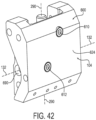
- Figs. 39-45 show a load adjustment base 600 and an adjustable bearing element 602.
- the load adjustment base 600 and adjustable bearing element 602 are in many respects similar to the above-referenced load adjustment bases 196, 530 and adjustable bearing elements 108 shown for example in Figs. 12-14 , 20 , 26 and 31-33 , and consequently the same reference numerals are used in Figs. 39-45 to denote structures corresponding to similar structures in the load adjustment bases 196, 530 and adjustable bearing elements 108.
- the foregoing description of the load adjustment bases 196, 530 and adjustable bearing elements 108 is equally applicable to the load adjustment base 600 and the adjustable bearing element 602 except as noted below.
- load adjustment bases 196, 530, 600 may be substituted for one another or used in conjunction with one another where applicable, and aspects of the adjustable bearing elements 108, 602 may be substituted for one another or used in conjunction with one another where applicable.
- the load adjustment base 600 and the adjustable bearing element 602 are configured to enable a specific range of adjustment of the adjustable pivot axis 142 of the adjustable bearing element 108 relative to the main pivot axis 132 of the proximal hub 104.
- a pair of socket head cap screws 610, 612 are provided in respective threaded openings in a rear wall 624 of the load adjustment base 600.
- Figs. 40 , 42 and 44 a pair of socket head cap screws 610, 612 are provided in respective threaded openings in a rear wall 624 of the load adjustment base 600.
- the centers of the screws 610, 612 are laterally spaced apart a distance X in a direction parallel to the main pivot axis 132, and vertically spaced apart a distance Y in a direction perpendicular to the main pivot axis 132.
- a pair of vertically extending slots 640, 642 are provided in a load adjustment nut 650 of the adjustable bearing element 602.
- the lateral spacing between the vertically extending slots 640, 642 is equal to the lateral spacing Y between the centers of the screws 610, 612.
- the screws 610, 612 and slots 640, 642 are on laterally opposite sides of the central axis 290 of the load adjustment screw 280.
- the tips 660, 662 of the respective socket head cap screws 610, 612 protrude forward from the rear wall 624 and are sized to fit within the respective slots 640, 642.
- One slot 640 has a lower abutment wall 670 and opens upward at a top surface 674 of the load adjustment nut 650 to define a vertical entranceway 680 for the screw 610.
- the other slot 642 has an upper abutment wall 672 and opens downward at a bottom surface 676 of the load adjustment nut 650 to define a vertical entranceway 682 for the screw 612.
- the lower and upper abutment walls 670, 672 of the load adjustment nut 650 define the respective upper and lower limits on the range of adjustment of the load adjustment nut 650, and thus, in reference to Figs.
- the adjustable pivot axis 142 moves vertically up and down relative to the main pivot axis 132 bound by the respective upper and lower limits on the adjustment range provided by the abutment walls 670, 672 of the load adjustment nut 650.
- Figs. 43 and 44 show an example of the lower limit.
- the upper abutment wall 672 of slot 642 eventually abuts the tip 662 of the socket head cap screw 612 thereby preventing further downward movement of the load adjustment nut 650.
- the Figs. 39-45 embodiment enables a specific range of adjustment of the adjustable pivot axis 142 relative to the main pivot axis 132.
- the range of adjustment can be changed without having to change the structure of the load adjustment base 600.
- the lower abutment location, L is vertically above the topmost portions of the diameters of the openings 690 that accommodate the laterally spaced pins 240 that form the main bearing element 130 (see Figs. 12 and 31 ) that defines the main pivot axis 132.
- the quantity of socket head cap screws 610, 612 and corresponding quantity of slots 640, 642 need not be limited to two as shown.
- a second pair of socket head cap screws and a second pair of slots further laterally spaced apart than the first pair of socket head cap screws 610, 612 and the first pair of slots 640, 642, for a total of four socket head cap screws and four slots, can be provided, where the second pair of socket head cap screws and second pair of slots define a different upper and lower limit on the range of adjustment than that of the first pair of socket head cap screws 610, 612 and first pair of slots 640, 642.
- the rear wall 624 of the load adjustment base 600 may include a plurality of vertically staggered threaded openings to allow the vertical height of the screws 610, 612 to be changed, thus allowing the corresponding range of adjustment of the adjustable pivot axis 142 relative to the main pivot axis 132 to be changed.
- either the upper adjustment limit mechanism 610, 640, 670 or the lower adjustment limit mechanism 612, 642, 672 may be omitted and a different limit mechanism substituted therefor; for example, substituting a top wall of the load adjustment base 196, 530 or an end-of-thread of the load adjustment screw 280 for the upper adjustment limit mechanism 610, 640, 670, and/or substituting the bottom wall 284 of the load adjustment base 196, 530 for the lower adjustment limit mechanism 612, 642, 672.
- Other combinations are also contemplated.
- protruding elements other than socket head cap screws 610, 612 may be used to fit within the slots 640, 642 to act as limits to the respective abutment walls 670, 672 of the adjustable bearing element 602.
- socket head cap screws 610, 612 may be inserted in respective threaded openings in the rear wall 624 of the load adjustment base 600, clips may be inserted through respective through holes in the rear wall 624, wherein the tips of the clips act as the limits to the respective abutment walls 670, 672.
- Figs. 46-54 show a load balancing arm 700 according to an embodiment of the invention.
- the load balancing arm 700 is in many respects similar to the above-referenced load balancing arms 100, 500 and consequently the same reference numerals are used to denote structures corresponding to similar structures in the load balancing arms 100, 500.
- the foregoing description of the load balancing arms 100, 500 is equally applicable to the load balancing arm 700 except as noted below.
- the load balancing arm 700 includes a proximal hub 104, an adjustable bearing element 108, a support arm 110, first and second springs 116, 718 and one or more links, two such links 124, 126 in the illustrative embodiment, as shown in Fig. 47 .
- the proximal hub 104 may include a support structure 24 such as the drop tube 24 (see Fig. 1 ).
- the proximal hub 104 includes a main bearing element 130 that defines a main pivot axis 132 (see Figs. 9 and 12-14 ).
- the adjustable bearing element 108 defines an adjustable pivot axis 142 that is adjustable relative to the main pivot axis 132. It is contemplated that the pivot axis 142 need not be adjustable relative to the main pivot axis 132 and, accordingly, the adjustable bearing element 108 and the adjustable pivot axis 142 may be referred to herein respectively as a link bearing element 108 and link pivot axis 142.
- the support arm 110 has a proximal end 150 and a distal end 152.
- the distal end 152 is configured to support a medical device load 36 (see Fig. 1 ) and the proximal end 150 is pivotably mounted to the main bearing element 130 for pivotable movement about the main pivot axis 132. Pivotable movement about the main pivot axis 132 raises and lowers the height of the medical device load 36 at the distal end 152.
- the first and second springs 116, 718 extend within a cavity 154 (see Fig. 7 ) of the support arm 110.
- the first spring 116 is mounted to exert a biasing force between the main pivot axis 132 and a distal end 158 of the first spring 116
- the second spring 718 is mounted to exert a biasing force between a proximal end 722 of the second spring 718 and a wall 728 at the distal end 152 of the support arm 110.
- the links 124, 126 each have a proximal end 160 and a distal end 162.
- the proximal end 160 is pivotably mounted to the link bearing element 108 for pivotable movement about the link pivot axis 142 (or, where an adjustable bearing element 108 is provided, pivotably mounted to the adjustable bearing element 108 for pivotable movement about the adjustable pivot axis 142).
- the distal ends 162 of the links 124, 126 are pivotably mounted to the distal end 158 of the first spring 116 and the proximal end 722 of the second spring 718 such that the biasing forces exerted by the first and second springs 116, 718 are transmitted through the links 124, 126 to the link bearing element 108 thereby to generate a moment about the main pivot axis 132 of the proximal hub 104 that counters a moment generated by the medical device load 36 at the distal end 152 of the support arm 110, thereby balancing the medical device load 36.
- the load balancing arm 700 there are two springs 116, 718, connected functionally in series, that together provide the load balancing arm 700 with an improved force transmission and a greater load bearing capacity, and thus a greater range of control than if the load balancing arm 700 had only a single spring; and these improvements are realized with minimal or no corresponding increase in the size of the load balancing arm 700.
- the Fig. 46 dual spring load balancing arm 700 has the same cross sectional area as that of the Fig. 2 single spring load balancing arm 100.
- the links 124, 126 connect at their proximal ends 160 to the bearing element 108 and at their distal ends 162 to the distal end 158 of the first spring 116.
- the attachment at the distal end 158 of the first spring 116 allows for a relatively longer link than if connected to the proximal end of the first spring 116, which has been found to allow for a better force transmission and less spring travel resulting in a more balanced load balancing arm 700 throughout the pivotable range of travel of the arm 700.
- the proximal end 150 of the support arm 110 of the load balancing arm 700 is identical in structure and function to that of the afore described load balancing arm 100 and thus for brevity further description thereof is omitted.
- the support arm 110 includes an intermediate portion 340 between the proximal end 150 and distal end 152 of the support arm 110.
- the intermediate portion 340 has a relatively narrower height span than the circular portion 178 of the proximal end 150 of the support arm 110.
- the links 124, 126 (only link 124 is in view in Figs. 52-54 ) have at least one bend that corresponds to the difference in height span between the intermediate portion 340 and the circular portion 178 (see Fig. 9 ) of the proximal end 150 of the support arm 110.
- the links 124, 126 have one bend and consequently have a J-shape in side view.
- the bend in the links 124, 126 aids in the load balancing arm 700 having a smaller size and lower overall cross section profile than if the links 124, 126 were straight.
- the smaller size and lower overall cross section profile make the load balancing arm 700 less obstructive in the operating room and improve the laminar airflow around the surface of the load balancing arm 700.
- the load balancing arm 700 includes a carriage slide 364 that is slidable relative to the support arm 110.
- the distal ends 162 of the links 124, 126 are pivotably mounted to the distal end 158 of the first spring 116 via the carriage slide 364.
- the pivotable connection may be facilitated by, for example, a pin 360 mounted within the carriage slide 364.
- the sliding connection between the carriage slide 364 and the support arm 110 for the load balancing arm 700 is identical to that of the carriage slide 364 and support arm 110 for the load balancing arm 100; as such, reference is made again to Fig. 7 . As shown in Fig.
- the carriage slide 364 is slidable within at least one groove 368 in the support arm 110, wherein in the illustrative embodiment there are two such grooves 368 at laterally opposite sides of the support arm 110.
- the grooves 368 are oriented along an axis that extends radially from and perpendicular to the main pivot axis 132 (see Figs. 9 and 12-14 ).
- the grooves 368 are formed by parallel ribs 370 in the inward facing walls of the support arm 110.
- the ribs 370 along with a box shape member in the lower portion of the support arm 110, also serve as stiffening members.
- the first and second springs 116, 718 of the load balancing arm 700 may be any type of counterbalancing member, and in the illustrative embodiment are, respectively, a compression gas spring 116 and a tension gas spring 718. Like the grooves 368, the first and second springs 116, 718 are oriented along an axis that extends radially from and perpendicular to the main pivot axis 132. In the illustrated embodiment, the first spring 116 is configured to expand and contract along a first axis and the second spring 718 is configured to expand and contract along a second axis, and the first and second axes coincide with one another.
- first and second springs 116, 718 may expand and contract along respective axes that do not coincide with one another, for example, where other components within the support arm 110 may impede the expansion and contraction of one or both of the first and second springs 116, 718, , in which case the first and second axes may be slightly offset from one another or at non-zero angles relative to one another.
- the first spring 116 of the load balancing arm 700 is similar in structure and function as the spring 116 of the load balancing arm 100 and, accordingly, reference is made to Figs. 11 , 12 and 15-17 and the corresponding description of the spring 116 of the load balancing arm 100.
- the first spring 116 has a cylinder 384 and a rod 388.
- the cylinder 384 has a proximal end wall 390 at a proximal end 394 of the first spring 116 that is coupled to a vertical beam 392 of the support arm 110. As shown in Fig.
- the vertical beam 392 extends from a top wall 406 to a bottom wall 408 of the support arm 110 and is sufficiently narrow that the links 124, 126 straddle the vertical beam 392 on opposite lateral sides thereof throughout the pivotable range of the load balancing arm 700.
- the proximal end wall 390 of the cylinder 384 may be coupled to the vertical beam 392 in any suitable manner, for example as by a protrusion 418, shown in Fig. 12 , that fits within an opening 420 in the vertical beam 392, shown in Fig. 11 .
- the rod 388 is pivotably mounted to the distal ends 162 of the links 124, 126 via the pin 360 of the afore described carriage slide 364. In operation, the links 124, 126 straddle the first spring 116 on laterally opposite sides of the first spring 116 throughout the pivotable range of the load balancing arm 700.
- the second spring 718 has a cylinder 784 and a rod 788.
- the cylinder 784 is connected to the carriage slide 364 and the rod 788 is connected to the wall 728 of the support arm 110 so that the second spring 718 exerts a biasing force that biases the carriage slide 364 and thus the distal ends 162 of the links 124, 126 toward the distal end 152 of the support arm 110.
- the cylinder 784 of the second spring 718 has a proximal end wall 790 at the proximal end 722 of the second spring 718 that is connected to the carriage slide 364 such that the proximal end wall 790 and the carriage slide 364 do not separate due to the biasing force.
- the proximal end 722 of the second spring 718, the carriage slide 364, and the distal end 158 of the first spring 116 are configured to move together in unison as the carriage slide 364 moves relative to the support arm 110.
- the cylinder 784 and the proximal end wall 790 of the second spring 718, the carriage slide 364, and the rod 388 of the first spring 116 are connected relative to each other and move together in unison as the carriage slide 364 moves relative to the support arm 110.
- the rod 788 of the second spring 718, or more generally a distal end 792 of the second spring 718, is connected to the wall 728 of the support arm 110 such that the rod 788 and the wall 728 do not separate due to the afore described biasing force.
- the proximal end wall 790 of the cylinder 784 may be connected to the carriage slide 364 to prevent separation therebetween in any suitable manner. Referring to Fig. 48 , the proximal end wall 790 of the cylinder 784 is connected to the carriage slide 364 by spot welding although it will be appreciated that brazing, riveting, soldering and/or adhesive glue may additionally or alternately be used.
- the proximal end wall 790 may be connected to the carriage slide 364 by an axially extending threaded protrusion of the proximal end wall 790 threadedly engaging a corresponding axially extending threaded opening in the carriage slide 364, or by a protrusion at the proximal end wall 790 being fitted within an opening in the carriage slide 364 in an interference-fit manner.
- the proximal end wall 790 may be connected to the carriage slide 364 by means of a pivotable connection, for example, by means of a transverse pin mounted within the carriage slide 364 pivotably received in a transverse bore in the proximal end wall 790.
- the proximal end 722 of the second spring 718 is pivotably connected to the carriage slide 364 to prevent separation between the proximal end 722 of the second spring 718 and the carriage slide 364 and also to provide tolerance for misalignment among the first and second springs 116, 718 and the carriage slide 364 axially relative to each another.
- the cylinder 784 of the second spring 718 and the rod 388 of the first spring 116 are connected to axially opposite ends of the carriage slide 364 in the slide direction of the carriage slide 364.
- the proximal end 722 of the second spring 718 and the distal end 158 of the first spring 116 are connected to axially opposite ends of the carriage slide 364 in the slide direction of the carriage slide 364.
- the cylinder 784 of the second spring 718 is pivotably mounted to the distal ends 162 of the links 124, 126 via the pin 360 of the carriage slide 364.
- the wall 728 of the support arm 110 may take any suitable form to provide support for the second spring 718 at the distal end 152 of the support arm 110.
- the wall 728 is an internal wall that is supported by and projects inward from a perimeter wall 774 of the support arm 110 that surrounds the first and second springs 116, 718.
- Laterally opposite convex portions 794 of the wall 728 are slidably fit within laterally opposite internal flanges 796 of the support arm 110.
- the internal flanges 796 prevent the convex portions 794 and thus the wall 728 from twisting during operation or during assembly of the load balancing arm 700.
- the internal flanges 796 are an axial extension of the ribs 370 that form the grooves 368 (see Fig. 7 ) within which the carriage slide 364 slides during operation.
- the internal flanges 796 of the support arm 110 are oriented along an axis that extends radially from and perpendicular to the main pivot axis 132.
- the internal flanges 796 of the support arm 110 are formed from the same extruded portion of the support arm 110 as the ribs 370 and grooves 368 that slidingly support the carriage slide 364.
- the wall 728 also includes axially facing bearing surfaces 802 that abut opposite facing axially facing bearing surfaces 804 of the internal flanges 796. Referring to Figs. 9 , 12 , 47-51 , the axially facing bearing surfaces 802 of the wall 728 face axially inward toward the main pivot axis 132, and the axially facing bearing surfaces 804 of the internal flanges 796 face axially outward away from the main pivot axis 132.
- the bearing surfaces 802 of the wall 728 abut the bearing surfaces 804 of the internal flanges 796 to prevent the wall 728, and thus the rod 788 and the distal end 792 of the second spring 718, from moving toward the main pivot axis 132 of the proximal hub 104 or the proximal end 150 of the support arm 110, due to the biasing force exerted by the second spring 718.
- the second spring 718 biases the carriage slide 364 toward the wall 728 of the support arm 110 and, in so doing, biases the carriage slide 364 and thus the distal ends 162 of the links 124, 126 toward the distal end 152 of the support arm 110 and correspondingly away from the proximal end 150 of the support arm 110.
- the wall 728 may be cast integrally with the support arm 110 as a monolithic structure, or the wall 728 may be fixed to, for example by fasteners, an internal projection of the support arm 110.
- the rod 788 of the second spring 718, or the distal end 792 of the second spring 718, may be connected to the wall 728 to prevent separation therebetween in any suitable manner.
- the rod 788 of the second spring 718, in the illustrated embodiment also the distal end 792 of the second spring 718, is connected to the wall 728 by spot welding although it will be appreciated that brazing, riveting, soldering and/or adhesive glue may additionally or alternately be used.
- the rod 788 of the second spring 718 may be connected to the wall 728 by a threaded portion of the distal end of the rod 788 threadedly engaging a corresponding axially extending threaded opening in the wall 728, or by the distal end of the rod 788 being fitted within an opening in the wall 728 in an interference-fit manner.
- the rod 788 may be connected to the wall 728 by means of a pivotable connection, for example, by means of a transverse pin mounted within the wall 728 pivotably received in a transverse bore in the rod 788.
- the distal end 792 of the second spring 718 is pivotably connected to the wall 728 to prevent separation between the distal end 792 of the second spring 718 and the wall 728 and also to provide tolerance for misalignment among the first and second springs 116, 718, the carriage slide 364, and the wall 728 axially relative to each another.
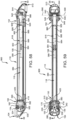
- Figs. 52-54 show the load balancing arm 700 in three different vertical positions
- Figs. 49-51 show the distal ends 162 of the links 124, 126 relative to the distal end 152 of the support arm 110 in the three respective vertical positions, as well as the corresponding biasing effects of the first and second springs 116, 718 in the three respective vertical positions.
- the links 124, 126 are shown adjusted to their maximum height in Figs. 49-54 (the height from axis 142 to axis 132 in Fig. 12 ), thereby maximizing the moment, or mechanical advantage, of the load balancing arm 700.
- the support arm 110 is in a substantially horizontal position.
- the first spring 116 is shown exerting a biasing force between the main pivot axis 132 and the distal end 158 of the first spring 116
- the second spring 718 is shown exerting a biasing force between the proximal end 722 of the second spring 718 and the wall 728 at the distal end 152 of the support arm 110.
- the first spring 116 is a tension spring
- the first spring 116 biases the distal ends 162 of the links 124, 126 toward the distal end 152 of the support arm 110 and thus away from the proximal end 150 of the support arm 110 and away from the main pivot axis 132.
- the second spring 718 is a compression spring 718 in the present embodiment
- the second spring 718 likewise biases the distal ends 162 of the links 124, 126 away from the proximal end 150 of the support arm 110 and away from the main pivot axis 132.
- both the first spring 116 and the second spring 718 contribute to the biasing force that biases the distal ends 162 of the links 124, 126 away from the proximal end 150 of the support arm 110 and away from the main pivot axis 132.
- the biasing forces exerted by the first and second springs 116, 718 are transmitted through the links 124, 126 to the link bearing element 108 thereby to generate a moment about the main pivot axis 132 of the proximal hub 104 that counters a moment generated by the medical device load at the distal end 152 of the support arm 110.
- the support arm 110 is shown pivoted about the main pivot axis 132 about 30 degrees upward relative to horizontal.
- the first spring 116 in Figs. 50 and 53 is shorter in length from its proximal end 394 to its distal end 158 and the second spring 718 is greater in length from its proximal end 722 to its distal end 792. Accordingly, in this position, the biasing force that the first spring 116 exerts to bias the distal ends 162 of the links 124, 126 toward the distal end 152 of the support arm 110 is less than that shown in Figs. 49 and 52 , and the biasing force that the second spring 718 exerts to bias the distal ends of the links 124, 126 toward the distal end 152 of the support arm 110 is less than that shown in Figs. 49 and 52 .
- the support arm 110 is shown pivoted about the main pivot axis 132 about 85 degrees downward from horizontal.
- the first spring 116 in Figs. 51 and 54 is greater in length from its proximal end 394 to its distal end 158 and the second spring 718 is shorter in length from its proximal end 722 to its distal end 792. Accordingly, in this position, the biasing force that the first spring 116 exerts to bias the distal ends 162 of the links 124, 126 toward the distal end 152 of the support arm 110 is greater than that shown in Figs. 49 and 52 , and the biasing force that the second spring 718 exerts to bias the distal ends of the links 124, 126 toward the distal end 152 of the support arm 110 is greater than that shown in Figs. 49 and 52 .
- the support arm 110 has an angle of rotation about the main pivot axis 132 of about 30 degrees upward from horizontal to about 85 degrees downward from horizontal.
- the first spring 116 includes a compression spring having the cylinder 384 and the rod 388 wherein the cylinder 384 includes the proximal end 394 of the first spring 116 and the rod 388 includes the distal end 158 of the first spring 116.
- the cylinder 384 and rod 388 may be switched so that the cylinder 384 includes the distal end 158 of the first spring 116 and the rod 388 includes the proximal end 394 of the first spring 116.
- the second spring 718 includes a tension spring having the cylinder 784 and the rod 788 wherein the cylinder 784 includes the proximal end 722 of the second spring 718 and the rod 788 includes the distal end 792 of the second spring 718.
- the cylinder 784 and rod 788 may be switched so that the cylinder 784 includes the distal end 792 of the second spring 718 and the rod 788 includes the proximal end 722 of the second spring 718.
- Figs. 55-66 show a load balancing arm 900 according to another embodiment of the invention.
- the load balancing arm 900 is in many respects similar to the above-referenced load balancing arms 100, 500, 700 and consequently the same reference numerals are used to denote structures corresponding to similar structures in the load balancing arms 100, 500, 700.
- the foregoing description of the load balancing arms 100, 500, 700 is equally applicable to the load balancing arm 900 except as noted below.
- the load balancing arm 900 includes a proximal hub 104, an adjustable bearing element 108, a support arm 110, first and second springs 116, 918 and one or more links, two such links 124, 126 in the illustrative embodiment, as shown in Fig. 55 .
- the proximal hub 104 may include a support structure 24 such as the drop tube 24 (see Fig. 1 ).
- the proximal hub 104 includes a main bearing element 130 that defines a main pivot axis 132 (see Figs. 26 and 33 ).
- the adjustable bearing element 108 defines an adjustable pivot axis 142 that is adjustable relative to the main pivot axis 132. It is contemplated that the pivot axis 142 need not be adjustable relative to the main pivot axis 132 and the adjustable bearing element 108 defines an adjustable pivot axis 142 that is adjustable relative to the main pivot axis 132. It is contemplated that the pivot axis 142 need not be adjustable relative to the main pivot axis 132 and, accordingly, the adjustable bearing element 108 and the adjustable pivot axis 142 may be referred to herein respectively as a link bearing element 108 and link pivot axis 142.
- the support arm 110 has a proximal end 150 and a distal end 152.
- the distal end 152 is pivotably mounted to the distal hub 510, which, in turn, is configured to support a medical device load 36 (see Fig. 1 ).
- the proximal end 150 is pivotably mounted to the main bearing element 130 for pivotable movement about the main pivot axis 132. The pivotable movement about the main pivot axis 132 raises and lowers the height of the medical device load 36 at the distal end 152.
- the first and second springs 116, 918 extend within a cavity 154 (see Fig. 29 ) of the support arm 110.
- the first spring 116 is mounted to exert a biasing force between the main pivot axis 132 and a distal end 158 of the first spring 116
- the second spring 918 is mounted to exert a biasing force between a proximal end 922 of the second spring 918 and a wall 928 at the distal end 152 of the support arm 110.
- the links 124, 126 each have a proximal end 160 and a distal end 162.
- the proximal end 160 is pivotably mounted to the link bearing element 108 for pivotable movement about the link pivot axis 142 (or, where an adjustable bearing element 108 is provided, pivotably mounted to the adjustable bearing element 108 for pivotable movement about the adjustable pivot axis 142).
- the distal ends 162 of the links 124, 126 are pivotably mounted to the distal end 158 of the first spring 116 and the proximal end 922 of the second spring 918 such that the biasing forces exerted by the first and second springs 116, 918 are transmitted through the links 124, 126 to the link bearing element 108 thereby to generate a moment about the main pivot axis 132 of the proximal hub 104 that counters a moment generated by the medical device load 36 at the distal end 152 of the support arm 110, thereby balancing the medical device load 36.
- the load balancing arm 900 there are two springs 116, 918, connected functionally in series, that together provide the load balancing arm 900 with an improved force transmission and a greater load bearing capacity, and thus a greater range of control than if the load balancing arm 900 had only a single spring; and these improvements are realized with minimal or no corresponding increase in the size of the load balancing arm 900.
- the Fig. 55 dual spring load balancing arm 900 has the same cross sectional area as that of the Fig. 21 single spring load balancing arm 500.
- the links 124, 126 connect at their proximal ends 160 to the bearing element 108 and at their distal ends 162 to the distal end 158 of the first spring 116.
- the attachment at the distal end 158 of the first spring 116 allows for a relatively longer link than if connected to the proximal end of the first spring 116, which has been found to allow for a better force transmission and less spring travel resulting in a more balanced load balancing arm 900 throughout the pivotable range of travel of the arm 900.
- the proximal end 150 of the support arm 110 of the load balancing arm 900 is identical in structure and function to that of the afore described load balancing arm 500 and thus for brevity further description thereof is omitted.
- the support arm 110 includes an intermediate portion 340 between the proximal end 150 and distal end 152 of the support arm 110.
- the intermediate portion 340 has a relatively narrower height span than the circular portion 178 of the proximal end 150 of the support arm 110.
- the links 124, 126 (only link 126 is shown in Figs. 64-66 ) have at least one bend that corresponds to the difference in height span between the intermediate portion 340 and the circular portion 178 (see Fig. 22 ) of the proximal end 150 of the support arm 110.
- the links 124, 126 have one bend and consequently have a J-shape in side view.
- the bend in the links 124, 126 aids in the load balancing arm 900 having a smaller size and lower overall cross section profile than if the links 124, 126 were straight.
- the smaller size and lower overall cross section profile make the load balancing arm 900 less obstructive in the operating room and improve the laminar airflow around the surface of the load balancing arm 900.
- the load balancing arm 900 includes a carriage slide 364 that is slidable relative to the support arm 110.
- the distal ends 162 of the links 124, 126 are pivotably mounted to the distal end 158 of the first spring 116 via the carriage slide 364.
- the pivotable connection may be facilitated by, for example, a pin 360 mounted within the carriage slide 364.
- the sliding connection between the carriage slide 364 and the support arm 110 for the load balancing arm 900 is identical to that of the carriage slide 364 and support arm 110 for the load balancing arm 500; as such, reference is made again to Fig. 29 . As shown in Fig.
- the carriage slide 364 is slidable within at least one groove 368 in the support arm 110, wherein in the illustrative embodiment there are two such grooves 368 at laterally opposite sides of the support arm 110.
- the grooves 368 are oriented along an axis that extends radially from and perpendicular to the main pivot axis 132 (see Figs. 26 and 33 ).
- the grooves 368 are formed by parallel ribs 370 in the inward facing walls of the support arm 110.
- the ribs 370 along with a horizontal cross beam the bottom portion of the support arm 110, also serve as stiffening members.
- the first and second springs 116, 918 of the load balancing arm 900 may be any type of counterbalancing member, and in the illustrative embodiment are, respectively, a compression gas spring 116 and a tension gas spring 918. Like the grooves 368, the first and second springs 116, 918 are oriented along an axis that extends radially from and perpendicular to the main pivot axis 132. In the illustrated embodiment, the first spring 116 is configured to expand and contract along a first axis and the second spring 918 is configured to expand and contract along a second axis, and the first and second axes coincide with one another.
- first and second springs 116, 918 may expand and contract along respective axes that do not coincide with one another, for example, where other components within the support arm 110 may impede the expansion and contraction of one or both of the first and second springs 116, 918, in which case the first and second axes may be slightly offset from one another or at non-zero angles relative to one another.
- the first spring 116 of the load balancing arm 900 is similar in structure and function as the spring 116 of the load balancing arm 500 and, accordingly, reference is made to Figs. 22 , 24 , 27 , and 32 and the corresponding description of the spring 116 of the load balancing arm 500.
- the first spring 116 has a cylinder 384 and a rod 388.
- the cylinder 384 has a proximal end wall 390 at a proximal end 394 of the first spring 116 that is coupled to a vertical beam 392 of the support arm 110. As shown in Fig.
- the vertical beam 392 extends from a top wall 406 to a bottom wall 408 of the support arm 110 and is sufficiently narrow that the links 124, 126 straddle the vertical beam 392 on opposite lateral sides thereof throughout the pivotable range of the load balancing arm 900.
- the proximal end wall 390 of the cylinder 384 may be coupled to the vertical beam 392 in any suitable manner, for example as by a protrusion 418, shown in Fig. 32 , that fits within an opening 420 in the vertical beam 392, shown in Figs. 24 and 25 .
- the rod 388 is pivotably mounted to the distal ends 162 of the links 124, 126 via the pin 360 of the afore described carriage slide 364. In operation, the links 124, 126 straddle the first spring 116 on laterally opposite sides of the first spring 116 throughout the pivotable range of the load balancing arm 900.
- the second spring 918 has a rod 984 and a cylinder 988.
- the rod 984 is connected to the carriage slide 364 and the cylinder 988 is connected to the wall 928 of the support arm 110 so that the second spring 918 exerts a biasing force that biases the carriage slide 364 and thus the distal ends 162 of the links 124, 126 toward the distal end 152 of the support arm 110.
- the rod 984 of the second spring 918 in the illustrated embodiment also the proximal end 922 of the second spring 918, is connected to the carriage slide 364 such that the rod 984 and the carriage slide 364 do not separate due to the biasing force.
- the proximal end 922 of the second spring 918, the carriage slide 364, and the distal end 158 of the first spring 116 are configured to move together in unison as the carriage slide 364 moves relative to the support arm 110.
- the rod 984 of the second spring 918, the carriage slide 364, and the rod 388 of the first spring 116 are connected relative to each other and move together in unison as the carriage slide 364 moves relative to the support arm 110.
- the cylinder 988 of the second spring 918 is connected to the wall 928 of the support arm 110 such that the cylinder 988 and the wall 928 do not separate due to the afore described biasing force.
- the rod 984 of the second spring 918, or the proximal end 922 of the second spring 918, may be connected to the carriage slide 364 to prevent separation therebetween in any suitable manner.
- the rod 984 of the second spring 918 is connected to the carriage slide 364 by spot welding although it will be appreciated that brazing, riveting, soldering and/or adhesive glue may additionally or alternately be used.
- the rod 984 may be connected to the carriage slide 364 by a threaded portion of the proximal end of the rod 984 threadedly engaging a corresponding axially extending threaded opening in the carriage slide 364, or by the proximal end of the rod 984 being fitted within an opening in the carriage slide 364 in an interference-fit manner.
- the rod 984 may be connected to the carriage slide 364 by means of a pivotable connection, for example, by means of a transverse pin mounted within the carriage slide 364 pivotably received in a transverse bore in the carriage slide 364.
- the proximal end 922 of the second spring 918 is pivotably connected to the carriage slide 364 to prevent separation between the proximal end 922 of the second spring 918 and the carriage slide 364 and also to provide tolerance for misalignment among the first and second springs 116, 918 and the carriage slide 364 axially relative to each another.
- the rod 984 of the second spring 918 and the rod 388 of the first spring 116 are connected to axially opposite ends of the carriage slide 364 in the slide direction of the carriage slide 364.
- the proximal end 922 of the second spring 918 and the distal end 158 of the first spring 116 are connected to axially opposite ends of the carriage slide 364 in the slide direction of the carriage slide 364.
- the rod 984 of the second spring 918 is pivotably mounted to the distal ends 162 of the links 124, 126 via the pin 360 of the carriage slide 364.
- the wall 928 of the support arm 110 may take any suitable form to provide support for the second spring 918 at the distal end 152 of the support arm 110.
- the wall 928 is an internal wall that is supported by and projects inward from a perimeter wall 974 of the support arm 110 that surrounds the first and second springs 116, 718.
- the wall 928 is cast integrally with the support arm 110 as a monolithic structure.
- the cylinder 988 of the second spring 918 has a distal end wall 990 at the distal end 992 of the second spring 918 that is connected to the wall 928.
- the connection between the wall 928 and the cylinder 988 of the second spring 918 prevents the cylinder 988 and the distal end 992 of the second spring 918 from moving toward the main pivot axis 132 of the proximal hub 104 or the proximal end 150 of the support arm 110, due to the biasing force exerted by the second spring 918.
- the second spring 918 biases the carriage slide 364 toward the wall 928 of the support arm 110 and, in so doing, biases the carriage slide 364 and thus the distal ends 162 of the links 124, 126 toward the distal end 152 of the support arm 110 and correspondingly away from the proximal end 150 of the support arm 110.
- the wall 928 may be a different structure from the remainder of the support arm 110 and be fixed to, for example by fasteners, an internal projection of the support arm 110.
- the wall 928 may be structured and function in a manner similar to the wall 728 of the support arm 110 of the load balancing arm 700.
- the distal end wall 990 of the cylinder 988 may be connected to the wall 928 to prevent separation therebetween in any suitable manner. Referring to Figs. 56-59 and 61-63 , the distal end wall 990 of the cylinder 988 is connected to the wall 928 by spot welding although it will be appreciated that brazing, riveting, soldering and/or adhesive glue may additionally or alternately be used.
- the distal end wall 990 of the cylinder 988 may be connected to the wall 928 by an axially extending threaded protrusion of the distal end wall 990 threadedly engaging a corresponding axially extending threaded opening in the wall 928, or by a protrusion of the distal end wall 990 being fitted within an opening in the wall 928 in an interference-fit manner.
- the distal end wall 990 may be connected to the wall 928 by means of a pivotable connection, for example, by means of a transverse pin mounted within the wall 928 pivotably received in a transverse bore in the distal end wall 990.
- the distal end 992 of the second spring 918 is pivotably connected to the wall 928 to prevent separation between the distal end 992 of the second spring 918 and the wall 928 and also to provide tolerance for misalignment among the first and second springs 116, 918, the carriage slide 364, and the wall 928 axially relative to each another.
- Figs. 64-66 show the load balancing arm 900 in three different vertical positions
- Figs. 61-63 show the distal ends 162 of the links 124, 126 relative to the distal end 152 of the support arm 110 in the three respective vertical positions, as well as the corresponding biasing effects of the first and second springs 116, 918 in the three respective vertical positions.
- the links 124, 126 are shown adjusted to their maximum height in Figs. 61-66 (the height from axis 142 to axis 132 in Figs. 26 and 33 ), thereby maximizing the moment, or mechanical advantage, of the load balancing arm 900.
- the support arm 110 is in a substantially horizontal position.
- the first spring 116 is shown exerting a biasing force between the main pivot axis 132 and the distal end 158 of the first spring 116
- the second spring 918 is shown exerting a biasing force between the proximal end 922 of the second spring 918 and the wall 928 at the distal end 152 of the support arm 110.
- the first spring 116 is a tension spring
- the first spring 116 biases the distal ends 162 of the links 124, 126 toward the distal end 152 of the support arm 110 and thus away from the proximal end 150 of the support arm 110 and away from the main pivot axis 132.
- the second spring 918 is a compression spring 918 in the present embodiment
- the second spring 918 likewise biases the distal ends 162 of the links 124, 126 away from the proximal end 150 of the support arm 110 and away from the main pivot axis 132.
- both the first spring 116 and the second spring 918 contribute to the biasing force that biases the distal ends 162 of the links 124, 126 away from the proximal end 150 of the support arm 110 and away from the main pivot axis 132.
- the biasing forces exerted by the first and second springs 116, 918 are transmitted through the links 124, 126 to the link bearing element 108 thereby to generate a moment about the main pivot axis 132 of the proximal hub 104 that counters a moment generated by the medical device load at the distal end 152 of the support arm 110.
- the support arm 110 is shown pivoted about the main pivot axis 132 about 30 degrees upward relative to horizontal.
- the first spring 116 in Figs. 62 and 65 is shorter in length from its proximal end 394 to its distal end 158 and the second spring 918 is greater in length from its proximal end 922 to its distal end 992. Accordingly, in this position, the biasing force that the first spring 116 exerts to bias the distal ends 162 of the links 124, 126 toward the distal end 152 of the support arm 110 is less than that shown in Figs. 61 and 64 , and the biasing force that the second spring 918 exerts to bias the distal ends of the links 124, 126 toward the distal end 152 of the support arm 110 is less than that shown in Figs. 61 and 64 .
- the support arm 110 is shown pivoted about the main pivot axis 132 about 85 degrees downward from horizontal.
- the first spring 116 in Figs. 63 and 66 is greater in length from its proximal end 394 to its distal end 158 and the second spring 918 is shorter in length from its proximal end 922 to its distal end 992.
- the biasing force that the first spring 116 exerts to bias the distal ends 162 of the links 124, 126 toward the distal end 152 of the support arm 110 is greater than that shown in Figs. 61 and 64
- the biasing force that the second spring 918 exerts to bias the distal ends of the links 124, 126 toward the distal end 152 of the support arm 110 is greater than that shown in Figs. 61 and 64 .
- the support arm 110 has an angle of rotation about the main pivot axis 132 of about 30 degrees upward from horizontal to about 85 degrees downward from horizontal.
- the first spring 116 includes a compression spring having the cylinder 384 and the rod 388 wherein the cylinder 384 includes the proximal end 394 of the first spring 116 and the rod 388 includes the distal end 158 of the first spring 116.
- the cylinder 384 and rod 388 may be switched so that the cylinder 384 includes the distal end 158 of the first spring 116 and the rod 388 includes the proximal end 394 of the first spring 116.
- the second spring 918 includes a tension spring having the rod 984 and the cylinder 988 wherein the rod 984 includes the proximal end 922 of the second spring 918 and the cylinder 988 includes the distal end 992 of the second spring 918.
- the rod 984 and cylinder 988 may be switched so that the rod 984 includes the distal end 992 of the second spring 918 and the cylinder 988 includes the proximal end 922 of the second spring 918.
Landscapes
- Engineering & Computer Science (AREA)
- Health & Medical Sciences (AREA)
- General Engineering & Computer Science (AREA)
- Surgery (AREA)
- Life Sciences & Earth Sciences (AREA)
- Mechanical Engineering (AREA)
- Heart & Thoracic Surgery (AREA)
- Biomedical Technology (AREA)
- Pathology (AREA)
- Medical Informatics (AREA)
- Molecular Biology (AREA)
- Animal Behavior & Ethology (AREA)
- General Health & Medical Sciences (AREA)
- Public Health (AREA)
- Veterinary Medicine (AREA)
- Oral & Maxillofacial Surgery (AREA)
- Nuclear Medicine, Radiotherapy & Molecular Imaging (AREA)
- Manipulator (AREA)
Claims (15)
- Lastausgleichsarm (700) für ein Stützsystem für medizinische Vorrichtungen (10), umfassend:eine proximale Nabe (104), die ein Hauptlagerelement (130) beinhaltet, das eine Hauptschwenkachse (132) definiert;ein Gliedlagerelement (108), das eine Gliedschwenkachse (142) definiert;einen Stützarm (110), der ein proximales Ende (150) und ein distales Ende (152) aufweist, wobei das distale Ende (152) konfiguriert ist, um eine Last einer medizinischen Vorrichtung (36) zu tragen, und das proximale Ende (150) schwenkbar an dem Hauptlagerelement (130) für eine Schwenkbewegung um die Hauptschwenkachse (132) montiert ist; dadurch gekennzeichnet, dasssich eine erste Feder (116) innerhalb eines Hohlraums (154) des Stützarms (110) erstreckt und montiert ist, um eine Vorspannkraft zwischen der Hauptschwenkachse (132) und einem distalen Ende (158) der ersten Feder (116) auszuüben;sich eine zweite Feder (718) innerhalb des Hohlraums (154) des Stützarms (110) erstreckt und montiert ist, um eine Vorspannkraft zwischen einem proximalen Ende (722) der zweiten Feder (718) und einer Wand (728) an dem distalen Ende (152) des Stützarms (110) auszuüben; undmindestens ein Glied (124, 126) ein proximales Ende (160), das schwenkbar an dem Gliedlagerelement (108) für eine Schwenkbewegung um die Gliedschwenkachse (142) montiert ist, und ein distales Ende (162) aufweist, das derart schwenkbar an dem distalen Ende (158) der ersten Feder (116) und dem proximalen Ende (722) der zweiten Feder (718) montiert ist, dass die von der ersten und der zweiten Feder (116, 718) ausgeübten Vorspannkräfte durch das Glied (124, 126) auf das Gliedlagerelement (108) übertragen werden, um dadurch ein Moment um die Hauptschwenkachse (132) der proximalen Nabe (104) zu erzeugen, das einem durch die Last der medizinischen Vorrichtung (36) an dem distalen Ende des Stützarms (110) erzeugten Moment entgegenwirkt.
- Lastausgleichsarm nach Anspruch 1, wobei die erste Feder (116) und die zweite Feder (718) funktionell in Reihe verbunden sind.
- Lastausgleichsarm nach einem der Ansprüche 1 bis 2, wobei die erste und zweite Feder (116, 718) entlang einer Achse ausgerichtet sind, die sich radial von und senkrecht zu der Hauptschwenkachse (132) erstreckt.
- Lastausgleichsarm nach einem der Ansprüche 1 bis 3, wobei die erste Feder (116) konfiguriert ist, um sich entlang einer ersten Achse auszudehnen und zusammenzuziehen, und die zweite Feder (718) konfiguriert ist, um sich entlang einer zweiten Achse auszudehnen und zusammenzuziehen, wobei die erste und die zweite Achse miteinander übereinstimmen.
- Lastausgleichsarm nach einem der Ansprüche 1 bis 4, wobei die Vorspannkraft der ersten Feder (116) konfiguriert ist, um das distale Ende (162) des mindestens einen Glieds (124, 126) in Richtung der Hauptschwenkachse (132) an dem proximalen Ende (150) des Stützarms (110) vorzuspannen, und die Vorspannkraft der zweiten Feder (718) konfiguriert ist, um das distale Ende (162) des mindestens einen Glieds (124, 126) in Richtung der Wand (728) an dem distalen Ende (152) des Stützarms (110) vorzuspannen.
- Lastausgleichsarm nach einem der Ansprüche 1 bis 5, wobei die Gliedschwenkachse (142) axial von der Hauptschwenkachse (132) beabstandet ist.
- Lastausgleichsarm nach einem der Ansprüche 1 bis 6, wobei das Gliedlagerelement (108) ein einstellbares Lagerelement ist, wobei die Gliedschwenkachse (142) relativ zu der Hauptschwenkachse (132) axial einstellbar ist.
- Lastausgleichsarm nach einem der Ansprüche 1 bis 7, ferner umfassend einen Laufwagenschlitten (364), der relativ zu dem Stützarm (110) verschiebbar ist, wobei das distale Ende (162) des Glieds (124, 126) über den Laufwagenschlitten (364) schwenkbar an dem distalen Ende (158) der ersten Feder (116) und an dem proximalen Ende (722) der zweiten Feder (718) montiert ist.
- Lastausgleichsarm nach Anspruch 8, wobei das proximale Ende (722) der zweiten Feder (718) und das distale Ende (158) der ersten Feder (116) mit axial gegenüberliegenden Enden des Laufwagenschlittens (364) verbunden sind.
- Lastausgleichsarm nach Anspruch 8, wobei der Laufwagenschlitten (364) in mindestens einer Nut (368) in dem Stützarm (110) verschiebbar ist.
- Lastausgleichsarm nach einem der Ansprüche 1 bis 10, wobei die Wand (728) eine Innenwand ist, die von einer Umfangswand des Stützarms (110), die die erste und zweite Feder (116, 718) umgibt, gestützt ist und nach innen ragt.
- Lastausgleichsarm nach einem der Ansprüche 1 bis 11, wobei die erste und zweite Feder (116, 718) Gasfedern sind, die einen Zylinder und eine Stange aufweisen, und die Stange (388) der ersten Feder (116) und der Zylinder (784) der zweiten Feder (718) schwenkbar an dem distalen Ende (162) des mindestens einen Glieds (124, 126) montiert sind.
- Lastausgleichsarm nach einem der Ansprüche 1 bis 12, wobei der Stützarm (110) einen Zwischenabschnitt (340) zwischen dem proximalen Ende (150) und dem distalen Ende (152) des Stützarms beinhaltet und der Zwischenabschnitt (340) eine relativ geringere Höhenspanne als das proximale Ende (150) des Stützarms (110) aufweist und wobei das mindestens eine Glied (124, 126) mindestens eine Biegung aufweist, die der Differenz in der Höhenspanne zwischen dem Zwischenabschnitt (340) und dem proximalen Ende (150) des Stützarms (110) entspricht.
- Lastausgleichsarm nach einem der Ansprüche 1 bis 13, wobei der Stützarm (110) einen Rotationswinkel um die Hauptschwenkachse (132) von etwa 30 Grad nach oben aus der Horizontalen bis etwa 85 Grad nach unten aus der Horizontalen aufweist.
- Lastausgleichsarm nach einem der Ansprüche 1 bis 14, ferner umfassend ein paralleles Glied (520), das an seinem proximalen Ende (580) schwenkbar mit einem Stift (582), der von der proximalen Nabe (104) gestützt ist, und an seinem distalen Ende (586) mit einem Stift verbunden ist, der von einer distalen Nabe (510) gestützt ist, die schwenkbar mit dem distalen Ende (152) des Stützarms (110) verbunden ist.
Applications Claiming Priority (2)
| Application Number | Priority Date | Filing Date | Title |
|---|---|---|---|
| US202163256713P | 2021-10-18 | 2021-10-18 | |
| PCT/US2022/046160 WO2023069269A1 (en) | 2021-10-18 | 2022-10-10 | Load balancing arm for medical device support system |
Publications (2)
| Publication Number | Publication Date |
|---|---|
| EP4419040A1 EP4419040A1 (de) | 2024-08-28 |
| EP4419040B1 true EP4419040B1 (de) | 2025-06-18 |
Family
ID=84329433
Family Applications (1)
| Application Number | Title | Priority Date | Filing Date |
|---|---|---|---|
| EP22800930.4A Active EP4419040B1 (de) | 2021-10-18 | 2022-10-10 | Lastausgleichsarm für stützsystem für medizinische vorrichtungen |
Country Status (4)
| Country | Link |
|---|---|
| US (1) | US12123546B2 (de) |
| EP (1) | EP4419040B1 (de) |
| AU (1) | AU2022370215B2 (de) |
| WO (1) | WO2023069269A1 (de) |
Families Citing this family (4)
| Publication number | Priority date | Publication date | Assignee | Title |
|---|---|---|---|---|
| US12064379B2 (en) * | 2019-02-22 | 2024-08-20 | American Sterilizer Company | Mounting plate for medical device suspension system |
| US20240142043A1 (en) * | 2022-10-31 | 2024-05-02 | Cnh Industrial America Llc | System for mounting multiple displays within a cab of an agricultural vehicle |
| CN218626163U (zh) * | 2022-11-18 | 2023-03-14 | 东莞市歌声美实业有限公司 | 带配重的拍摄支架 |
| CN119914805A (zh) * | 2023-10-31 | 2025-05-02 | 南京迈瑞生物医疗电子有限公司 | 支撑臂装置和医疗装置 |
Family Cites Families (82)
| Publication number | Priority date | Publication date | Assignee | Title |
|---|---|---|---|---|
| US2150975A (en) | 1936-07-20 | 1939-03-21 | Aaron S Green | Instrument supporting device |
| US2941776A (en) | 1957-05-13 | 1960-06-21 | Ritter Co Inc | Counterbalancing mechanism |
| DE1193897B (de) | 1961-12-04 | 1965-06-03 | Quarzlampen Gmbh | Operationsleuchte mit Schwenkarm |
| US3547390A (en) | 1968-05-31 | 1970-12-15 | Edna A Mehr | Adjustable bracket structure |
| JPS5258284A (en) | 1975-10-28 | 1977-05-13 | Jacobsen As J | Arm with balance spring |
| US4160536A (en) | 1976-10-27 | 1979-07-10 | Jac. Jacobsen A/S | Counterbalanced arm |
| US4447031A (en) | 1981-04-13 | 1984-05-08 | Positioning Devices, Inc. | Spring counterbalanced support arm system |
| JPS585405U (ja) | 1981-07-03 | 1983-01-13 | 株式会社モリタ製作所 | 歯科用ライト装置のハンガ−ア−ム機構 |
| US4695024A (en) | 1986-05-09 | 1987-09-22 | Attain, Inc. | Test system manipulator arm |
| US4770384A (en) | 1986-07-28 | 1988-09-13 | Matsushita Electric Works, Ltd. | Movable stand |
| US4744019A (en) | 1986-09-12 | 1988-05-10 | Jac Jacobsen A/S | Counterbalanced arm assembly |
| US4836478A (en) | 1987-10-15 | 1989-06-06 | Ergotron, Inc. | Suspension system for personal computers and monitors |
| JP2538953B2 (ja) | 1987-11-17 | 1996-10-02 | 三菱重工業株式会社 | 工業用ロボットのバランス機構 |
| DE3933596A1 (de) | 1989-10-07 | 1991-04-18 | Heraeus Instr Gmbh | Operationsleuchte mit verstellbarer halterung |
| EP0445331A1 (de) | 1990-03-07 | 1991-09-11 | First National Investments Ltd. | Schwenkarm für eine Tragplatte, insbesondere eine Monitortragplatte |
| US5186337A (en) | 1991-08-09 | 1993-02-16 | Hill-Rom Company, Inc. | Pivoted power column |
| US5348260A (en) | 1993-02-08 | 1994-09-20 | Hughes Aircraft Company | Movable supporting arm |
| US5738316A (en) | 1995-04-03 | 1998-04-14 | Ergotron, Inc. | Vertical work center |
| US5618090A (en) | 1995-05-12 | 1997-04-08 | Medaes, Inc. | Movable hospital room equipment column |
| US6076785A (en) | 1996-02-29 | 2000-06-20 | Innovative Office Products, Inc. | Ergonomic sit/stand keyboard support mechanism |
| US5743503A (en) | 1996-03-08 | 1998-04-28 | Ergotron, Inc. | Computer suspension system |
| US5826846A (en) | 1996-06-28 | 1998-10-27 | Hill-Rom, Inc. | Monitor arm with constant counterbalance |
| US5799917A (en) | 1996-12-17 | 1998-09-01 | Li; Chin-Chu | Adjustable supporting bracket |
| US6012693A (en) | 1998-02-19 | 2000-01-11 | Ergotron, Inc. | Multi-function display mounting system |
| US6012821A (en) | 1998-03-30 | 2000-01-11 | Hill-Rom, Inc. | Support arm for surgical light apparatus |
| US6328458B1 (en) | 1998-03-30 | 2001-12-11 | Hill-Rom Services, Inc. | Support arm for surgical light apparatus |
| US6478274B1 (en) | 1999-05-10 | 2002-11-12 | Innovative Office Products, Inc. | Arm apparatus for mounting electronic devices |
| US6609691B2 (en) | 1999-06-07 | 2003-08-26 | Innovative Office Products, Inc. | Arm apparatus for mounting electronic devices with cable management system |
| US6471363B2 (en) | 1999-12-23 | 2002-10-29 | Hill-Rom Services, Inc. | Surgical theater system having light, monitors, and cameras |
| US7097145B2 (en) * | 2001-09-14 | 2006-08-29 | Hill-Rom Services, Inc. | Support arm for a surgical theater system |
| WO2003025453A1 (en) | 2001-09-14 | 2003-03-27 | Hill-Rom Services, Inc. | Support arm for a surgical theater system |
| US6819550B2 (en) | 2001-11-08 | 2004-11-16 | Apple Computer, Inc. | Computer controlled display device |
| US6736364B2 (en) | 2002-02-01 | 2004-05-18 | Innovative Office Products, Inc. | Modular mounting arm |
| JP4138667B2 (ja) * | 2002-02-25 | 2008-08-27 | ステリス インコーポレイテッド | 調節可能な進行継手制動システム |
| DE10300620B4 (de) | 2002-05-18 | 2017-04-13 | Carl Zeiss Meditec Ag | Trägervorrichtung für ein medizinisch-optisches Gerät |
| US6592090B1 (en) | 2002-08-23 | 2003-07-15 | Chin-Chu Li | Object supporting structure |
| US7014157B2 (en) | 2002-10-31 | 2006-03-21 | Innovative Office Products, Inc. | Friction cylinder for a support device |
| US7252277B2 (en) * | 2003-01-17 | 2007-08-07 | Ergotron, Inc. | Support arm |
| US7464909B2 (en) | 2004-11-12 | 2008-12-16 | Chin-Chu Li | Supporting shelf |
| US7837674B2 (en) | 2005-01-24 | 2010-11-23 | Intuitive Surgical Operations, Inc. | Compact counter balance for robotic surgical systems |
| DE102005017487A1 (de) | 2005-04-15 | 2006-10-19 | Sachtler Gmbh & Co. Kg | Federarm und Körperstativ |
| US7364127B2 (en) | 2005-06-07 | 2008-04-29 | Ming-Hua Huang | Support arm for a monitor |
| US20070001076A1 (en) | 2005-06-29 | 2007-01-04 | Saeb Asamarai | Support arm and method with variable counterbalance |
| US8342467B2 (en) | 2005-10-04 | 2013-01-01 | Eric Ronald Stachowski | Apparatus for hand control, pressure amplification, and stabilization of medical and industrial devices |
| US7770860B1 (en) | 2005-11-10 | 2010-08-10 | Modular Services Company | Medical service system on articulating arm with electromagnetic brakes |
| DE102006014217B3 (de) | 2006-03-28 | 2007-05-16 | Draeger Medical Ag | Tragevorrichtung |
| US7997211B2 (en) | 2006-06-12 | 2011-08-16 | Steelcase Inc. | Wall mounted workstation |
| US7395995B2 (en) | 2006-07-19 | 2008-07-08 | Hoolin Research Company Limited | Monitor support structure |
| EP2217412B1 (de) | 2007-09-26 | 2014-07-02 | Robarts Research Institute | Ausgleichsanordnung |
| KR100922872B1 (ko) | 2008-01-07 | 2009-10-20 | 곽수만 | 디스플레이장치용 암 스탠드 |
| US7661643B2 (en) | 2008-02-04 | 2010-02-16 | Clo Systems | Swivel mount system for a monitor |
| CN101684882B (zh) * | 2008-09-25 | 2012-07-18 | 鸿富锦精密工业(深圳)有限公司 | 升降机构 |
| US8070120B2 (en) | 2008-11-19 | 2011-12-06 | Hoffman Enclosures, Inc. | Vertical motion pendant arm |
| US8439319B2 (en) | 2009-05-19 | 2013-05-14 | Denis Page | Standalone, mobile and adjustable stand and tray |
| US20110147546A1 (en) | 2009-12-23 | 2011-06-23 | Humanscale Corporation | Adjustable Display Arm |
| US20110260017A1 (en) | 2010-04-23 | 2011-10-27 | Humanscale Corporation | Adjustable Support Arm |
| US9316346B2 (en) | 2010-06-09 | 2016-04-19 | Colebrook Bosson Saunders (Products) Limited | Support system |
| US9277812B2 (en) | 2010-07-08 | 2016-03-08 | Southco, Inc. | Display support with first and second arms and mechanism for maintaining constant orientation of the plane bisecting the range of rotation of the second arm relative to a support base |
| US9188275B2 (en) | 2010-07-30 | 2015-11-17 | Ergotron, Inc. | Edge mount positioning apparatus, system, and method |
| CN103477143B (zh) | 2011-02-11 | 2016-09-28 | 爱格升公司 | 双焦显示器定位设备和方法 |
| US8430564B2 (en) | 2011-02-28 | 2013-04-30 | General Electric Company | Sliding counterbalanced C-arm positioning devices and methods for using such devices |
| US8465203B2 (en) | 2011-03-02 | 2013-06-18 | General Electric Company | Brake systems for C-arm positioning devices, apparatus containing the same and methods for using such systems |
| US9228696B2 (en) | 2011-03-18 | 2016-01-05 | GCX Corporation | Variable height arm structures, systems, and methods |
| US20130112828A1 (en) | 2011-06-07 | 2013-05-09 | Knoll, Inc. | Support Apparatus for Display Devices and Other Objects |
| US9657889B1 (en) * | 2013-03-15 | 2017-05-23 | Humanscale Corporation | Adjustable support arm |
| EP3172153A4 (de) | 2014-02-07 | 2018-02-21 | Centre for Imaging Technology Commercialization | Modularer sockelverbindung für einen ausgleichenden arm |
| JP2016030315A (ja) | 2014-07-29 | 2016-03-07 | 株式会社安川電機 | ロボット |
| US10285772B2 (en) * | 2014-11-10 | 2019-05-14 | Ondal Medical Systems Gmbh | Support joint for a carrier arm of a medical stand device |
| WO2016154709A1 (en) | 2015-03-31 | 2016-10-06 | Centre For Imaging Technology Commercialization (Cimtec) | A counterbalancing apparatus for gimbal joints and/or a method for counterbalancing a load on a gimbal joint |
| WO2016154708A1 (en) | 2015-03-31 | 2016-10-06 | Centre For Imaging Technology Commercialization (Cimtec) | A counterbalance system and/or a method for counterbalancing a load |
| TWM520228U (zh) | 2015-11-26 | 2016-04-11 | 青輔實業股份有限公司 | 可鎖定位置的螢幕支撐裝置 |
| TWM520210U (zh) | 2015-12-01 | 2016-04-11 | 青輔實業股份有限公司 | 具有旋轉關節迫緊功能的螢幕支撐裝置 |
| US11191608B2 (en) | 2017-03-08 | 2021-12-07 | American Sterilizer Company | Aerodynamically shaped surgical lighting suspension |
| CA3004672A1 (en) | 2017-06-09 | 2018-12-09 | Teknion Limited | Adjustable counterbalancing display support |
| CA3016889A1 (en) | 2017-09-08 | 2019-03-08 | Aaron Fenster | A counterbalancing mechanism and stabilizer design and method for counterbalancing and stabilizing a load |
| US10591006B2 (en) | 2017-11-10 | 2020-03-17 | American Sterilizer Company | Automatically actuated split-collar active mechanical brake for surgical lighting systems |
| US20200025326A1 (en) | 2018-07-19 | 2020-01-23 | Visioner Inc. | Novel holder |
| TWI663359B (zh) | 2018-08-08 | 2019-06-21 | 青輔實業股份有限公司 | 可調式懸臂裝置 |
| TWI678610B (zh) | 2018-08-21 | 2019-12-01 | 青輔實業股份有限公司 | 懸臂式支撐裝置 |
| EP3917439B1 (de) * | 2019-01-31 | 2022-10-12 | American Sterilizer Company | Lastausgleichsarm für ein stützsystem eines medizinprodukts |
| US11320090B2 (en) * | 2019-11-21 | 2022-05-03 | Oasys Healthcare Corporation | Arm linkage for device bearing spring arms |
| AU2021369503B2 (en) * | 2020-10-30 | 2025-05-22 | American Sterilizer Company | Parallelism adjustment mechanism for load balancing arm |
-
2022
- 2022-10-10 EP EP22800930.4A patent/EP4419040B1/de active Active
- 2022-10-10 AU AU2022370215A patent/AU2022370215B2/en active Active
- 2022-10-10 WO PCT/US2022/046160 patent/WO2023069269A1/en not_active Ceased
- 2022-10-10 US US17/962,762 patent/US12123546B2/en active Active
Also Published As
| Publication number | Publication date |
|---|---|
| AU2022370215B2 (en) | 2024-12-19 |
| US12123546B2 (en) | 2024-10-22 |
| EP4419040A1 (de) | 2024-08-28 |
| US20230120143A1 (en) | 2023-04-20 |
| CA3233916A1 (en) | 2023-04-27 |
| WO2023069269A1 (en) | 2023-04-27 |
| AU2022370215A1 (en) | 2024-04-04 |
Similar Documents
| Publication | Publication Date | Title |
|---|---|---|
| EP4419040B1 (de) | Lastausgleichsarm für stützsystem für medizinische vorrichtungen | |
| EP3917439B1 (de) | Lastausgleichsarm für ein stützsystem eines medizinprodukts | |
| US8038108B2 (en) | Supporting apparatus for medical instrument | |
| JP6712298B2 (ja) | 軟組織リトラクター及びブレード | |
| US6364268B1 (en) | Ceiling mount | |
| US10285772B2 (en) | Support joint for a carrier arm of a medical stand device | |
| JP2013144149A (ja) | ロボット外科手術システムのための小型のカウンタバランス | |
| CA3233916C (en) | Load balancing arm for medical device support system | |
| US10973477B2 (en) | Portable X-ray | |
| EP4236897B1 (de) | Parallelismusanpassungsmechanismus für lastausgleichsarm | |
| CA3196763C (en) | Parallelism adjustment mechanism for load balancing arm | |
| US7922138B2 (en) | Dental apparatus having an adjustable articulated arm |
Legal Events
| Date | Code | Title | Description |
|---|---|---|---|
| STAA | Information on the status of an ep patent application or granted ep patent |
Free format text: STATUS: UNKNOWN |
|
| STAA | Information on the status of an ep patent application or granted ep patent |
Free format text: STATUS: THE INTERNATIONAL PUBLICATION HAS BEEN MADE |
|
| PUAI | Public reference made under article 153(3) epc to a published international application that has entered the european phase |
Free format text: ORIGINAL CODE: 0009012 |
|
| STAA | Information on the status of an ep patent application or granted ep patent |
Free format text: STATUS: REQUEST FOR EXAMINATION WAS MADE |
|
| 17P | Request for examination filed |
Effective date: 20240212 |
|
| AK | Designated contracting states |
Kind code of ref document: A1 Designated state(s): AL AT BE BG CH CY CZ DE DK EE ES FI FR GB GR HR HU IE IS IT LI LT LU LV MC ME MK MT NL NO PL PT RO RS SE SI SK SM TR |
|
| P01 | Opt-out of the competence of the unified patent court (upc) registered |
Free format text: CASE NUMBER: APP_64096/2024 Effective date: 20241203 |
|
| DAV | Request for validation of the european patent (deleted) | ||
| DAX | Request for extension of the european patent (deleted) | ||
| GRAP | Despatch of communication of intention to grant a patent |
Free format text: ORIGINAL CODE: EPIDOSNIGR1 |
|
| STAA | Information on the status of an ep patent application or granted ep patent |
Free format text: STATUS: GRANT OF PATENT IS INTENDED |
|
| INTG | Intention to grant announced |
Effective date: 20250331 |
|
| GRAS | Grant fee paid |
Free format text: ORIGINAL CODE: EPIDOSNIGR3 |
|
| GRAA | (expected) grant |
Free format text: ORIGINAL CODE: 0009210 |
|
| STAA | Information on the status of an ep patent application or granted ep patent |
Free format text: STATUS: THE PATENT HAS BEEN GRANTED |
|
| AK | Designated contracting states |
Kind code of ref document: B1 Designated state(s): AL AT BE BG CH CY CZ DE DK EE ES FI FR GB GR HR HU IE IS IT LI LT LU LV MC ME MK MT NL NO PL PT RO RS SE SI SK SM TR |
|
| REG | Reference to a national code |
Ref country code: GB Ref legal event code: FG4D |
|
| REG | Reference to a national code |
Ref country code: CH Ref legal event code: EP |
|
| REG | Reference to a national code |
Ref country code: DE Ref legal event code: R096 Ref document number: 602022016199 Country of ref document: DE |
|
| REG | Reference to a national code |
Ref country code: CH Ref legal event code: EP |
|
| REG | Reference to a national code |
Ref country code: IE Ref legal event code: FG4D |
|
| PG25 | Lapsed in a contracting state [announced via postgrant information from national office to epo] |
Ref country code: FI Free format text: LAPSE BECAUSE OF FAILURE TO SUBMIT A TRANSLATION OF THE DESCRIPTION OR TO PAY THE FEE WITHIN THE PRESCRIBED TIME-LIMIT Effective date: 20250618 |
|
| REG | Reference to a national code |
Ref country code: LT Ref legal event code: MG9D |
|
| PG25 | Lapsed in a contracting state [announced via postgrant information from national office to epo] |
Ref country code: NO Free format text: LAPSE BECAUSE OF FAILURE TO SUBMIT A TRANSLATION OF THE DESCRIPTION OR TO PAY THE FEE WITHIN THE PRESCRIBED TIME-LIMIT Effective date: 20250918 Ref country code: GR Free format text: LAPSE BECAUSE OF FAILURE TO SUBMIT A TRANSLATION OF THE DESCRIPTION OR TO PAY THE FEE WITHIN THE PRESCRIBED TIME-LIMIT Effective date: 20250919 |
|
| PG25 | Lapsed in a contracting state [announced via postgrant information from national office to epo] |
Ref country code: BG Free format text: LAPSE BECAUSE OF FAILURE TO SUBMIT A TRANSLATION OF THE DESCRIPTION OR TO PAY THE FEE WITHIN THE PRESCRIBED TIME-LIMIT Effective date: 20250618 |
|
| PG25 | Lapsed in a contracting state [announced via postgrant information from national office to epo] |
Ref country code: HR Free format text: LAPSE BECAUSE OF FAILURE TO SUBMIT A TRANSLATION OF THE DESCRIPTION OR TO PAY THE FEE WITHIN THE PRESCRIBED TIME-LIMIT Effective date: 20250618 |
|
| PG25 | Lapsed in a contracting state [announced via postgrant information from national office to epo] |
Ref country code: RS Free format text: LAPSE BECAUSE OF FAILURE TO SUBMIT A TRANSLATION OF THE DESCRIPTION OR TO PAY THE FEE WITHIN THE PRESCRIBED TIME-LIMIT Effective date: 20250918 |
|
| REG | Reference to a national code |
Ref country code: NL Ref legal event code: MP Effective date: 20250618 |
|
| PG25 | Lapsed in a contracting state [announced via postgrant information from national office to epo] |
Ref country code: LV Free format text: LAPSE BECAUSE OF FAILURE TO SUBMIT A TRANSLATION OF THE DESCRIPTION OR TO PAY THE FEE WITHIN THE PRESCRIBED TIME-LIMIT Effective date: 20250618 |
|
| PG25 | Lapsed in a contracting state [announced via postgrant information from national office to epo] |
Ref country code: NL Free format text: LAPSE BECAUSE OF FAILURE TO SUBMIT A TRANSLATION OF THE DESCRIPTION OR TO PAY THE FEE WITHIN THE PRESCRIBED TIME-LIMIT Effective date: 20250618 |
|
| PG25 | Lapsed in a contracting state [announced via postgrant information from national office to epo] |
Ref country code: PT Free format text: LAPSE BECAUSE OF FAILURE TO SUBMIT A TRANSLATION OF THE DESCRIPTION OR TO PAY THE FEE WITHIN THE PRESCRIBED TIME-LIMIT Effective date: 20251020 |
|
| REG | Reference to a national code |
Ref country code: AT Ref legal event code: MK05 Ref document number: 1803506 Country of ref document: AT Kind code of ref document: T Effective date: 20250618 |
|
| PG25 | Lapsed in a contracting state [announced via postgrant information from national office to epo] |
Ref country code: IS Free format text: LAPSE BECAUSE OF FAILURE TO SUBMIT A TRANSLATION OF THE DESCRIPTION OR TO PAY THE FEE WITHIN THE PRESCRIBED TIME-LIMIT Effective date: 20251018 |
|
| PGFP | Annual fee paid to national office [announced via postgrant information from national office to epo] |
Ref country code: DE Payment date: 20251029 Year of fee payment: 4 |
|
| PG25 | Lapsed in a contracting state [announced via postgrant information from national office to epo] |
Ref country code: AT Free format text: LAPSE BECAUSE OF FAILURE TO SUBMIT A TRANSLATION OF THE DESCRIPTION OR TO PAY THE FEE WITHIN THE PRESCRIBED TIME-LIMIT Effective date: 20250618 Ref country code: SM Free format text: LAPSE BECAUSE OF FAILURE TO SUBMIT A TRANSLATION OF THE DESCRIPTION OR TO PAY THE FEE WITHIN THE PRESCRIBED TIME-LIMIT Effective date: 20250618 |
|
| PGFP | Annual fee paid to national office [announced via postgrant information from national office to epo] |
Ref country code: IT Payment date: 20251031 Year of fee payment: 4 |
|
| PGFP | Annual fee paid to national office [announced via postgrant information from national office to epo] |
Ref country code: FR Payment date: 20251027 Year of fee payment: 4 |
|
| PG25 | Lapsed in a contracting state [announced via postgrant information from national office to epo] |
Ref country code: CZ Free format text: LAPSE BECAUSE OF FAILURE TO SUBMIT A TRANSLATION OF THE DESCRIPTION OR TO PAY THE FEE WITHIN THE PRESCRIBED TIME-LIMIT Effective date: 20250618 |
|
| PG25 | Lapsed in a contracting state [announced via postgrant information from national office to epo] |
Ref country code: PL Free format text: LAPSE BECAUSE OF FAILURE TO SUBMIT A TRANSLATION OF THE DESCRIPTION OR TO PAY THE FEE WITHIN THE PRESCRIBED TIME-LIMIT Effective date: 20250618 |
|
| PG25 | Lapsed in a contracting state [announced via postgrant information from national office to epo] |
Ref country code: EE Free format text: LAPSE BECAUSE OF FAILURE TO SUBMIT A TRANSLATION OF THE DESCRIPTION OR TO PAY THE FEE WITHIN THE PRESCRIBED TIME-LIMIT Effective date: 20250618 |
|
| PG25 | Lapsed in a contracting state [announced via postgrant information from national office to epo] |
Ref country code: SK Free format text: LAPSE BECAUSE OF FAILURE TO SUBMIT A TRANSLATION OF THE DESCRIPTION OR TO PAY THE FEE WITHIN THE PRESCRIBED TIME-LIMIT Effective date: 20250618 |
|
| PG25 | Lapsed in a contracting state [announced via postgrant information from national office to epo] |
Ref country code: ES Free format text: LAPSE BECAUSE OF FAILURE TO SUBMIT A TRANSLATION OF THE DESCRIPTION OR TO PAY THE FEE WITHIN THE PRESCRIBED TIME-LIMIT Effective date: 20250618 |
|
| PG25 | Lapsed in a contracting state [announced via postgrant information from national office to epo] |
Ref country code: RO Free format text: LAPSE BECAUSE OF FAILURE TO SUBMIT A TRANSLATION OF THE DESCRIPTION OR TO PAY THE FEE WITHIN THE PRESCRIBED TIME-LIMIT Effective date: 20250618 |