EP4417462A1 - Battery swap platform and battery charging and swapping station - Google Patents
Battery swap platform and battery charging and swapping station Download PDFInfo
- Publication number
- EP4417462A1 EP4417462A1 EP23218691.6A EP23218691A EP4417462A1 EP 4417462 A1 EP4417462 A1 EP 4417462A1 EP 23218691 A EP23218691 A EP 23218691A EP 4417462 A1 EP4417462 A1 EP 4417462A1
- Authority
- EP
- European Patent Office
- Prior art keywords
- platform
- jacking
- battery
- positioning device
- battery swap
- Prior art date
- Legal status (The legal status is an assumption and is not a legal conclusion. Google has not performed a legal analysis and makes no representation as to the accuracy of the status listed.)
- Pending
Links
- 230000007246 mechanism Effects 0.000 claims description 29
- 239000003351 stiffener Substances 0.000 claims description 20
- 238000000034 method Methods 0.000 description 26
- 238000005192 partition Methods 0.000 description 26
- 230000008569 process Effects 0.000 description 21
- 238000004519 manufacturing process Methods 0.000 description 8
- 230000005540 biological transmission Effects 0.000 description 5
- 230000009467 reduction Effects 0.000 description 4
- 238000010586 diagram Methods 0.000 description 2
- 238000006467 substitution reaction Methods 0.000 description 2
- 230000005856 abnormality Effects 0.000 description 1
- 238000004891 communication Methods 0.000 description 1
- 230000000694 effects Effects 0.000 description 1
- 239000010720 hydraulic oil Substances 0.000 description 1
- 230000032258 transport Effects 0.000 description 1
- 238000003466 welding Methods 0.000 description 1
Images



Classifications
-
- B—PERFORMING OPERATIONS; TRANSPORTING
- B60—VEHICLES IN GENERAL
- B60L—PROPULSION OF ELECTRICALLY-PROPELLED VEHICLES; SUPPLYING ELECTRIC POWER FOR AUXILIARY EQUIPMENT OF ELECTRICALLY-PROPELLED VEHICLES; ELECTRODYNAMIC BRAKE SYSTEMS FOR VEHICLES IN GENERAL; MAGNETIC SUSPENSION OR LEVITATION FOR VEHICLES; MONITORING OPERATING VARIABLES OF ELECTRICALLY-PROPELLED VEHICLES; ELECTRIC SAFETY DEVICES FOR ELECTRICALLY-PROPELLED VEHICLES
- B60L53/00—Methods of charging batteries, specially adapted for electric vehicles; Charging stations or on-board charging equipment therefor; Exchange of energy storage elements in electric vehicles
- B60L53/80—Exchanging energy storage elements, e.g. removable batteries
-
- B—PERFORMING OPERATIONS; TRANSPORTING
- B60—VEHICLES IN GENERAL
- B60K—ARRANGEMENT OR MOUNTING OF PROPULSION UNITS OR OF TRANSMISSIONS IN VEHICLES; ARRANGEMENT OR MOUNTING OF PLURAL DIVERSE PRIME-MOVERS IN VEHICLES; AUXILIARY DRIVES FOR VEHICLES; INSTRUMENTATION OR DASHBOARDS FOR VEHICLES; ARRANGEMENTS IN CONNECTION WITH COOLING, AIR INTAKE, GAS EXHAUST OR FUEL SUPPLY OF PROPULSION UNITS IN VEHICLES
- B60K1/00—Arrangement or mounting of electrical propulsion units
- B60K1/04—Arrangement or mounting of electrical propulsion units of the electric storage means for propulsion
-
- H—ELECTRICITY
- H01—ELECTRIC ELEMENTS
- H01M—PROCESSES OR MEANS, e.g. BATTERIES, FOR THE DIRECT CONVERSION OF CHEMICAL ENERGY INTO ELECTRICAL ENERGY
- H01M10/00—Secondary cells; Manufacture thereof
- H01M10/42—Methods or arrangements for servicing or maintenance of secondary cells or secondary half-cells
- H01M10/44—Methods for charging or discharging
- H01M10/441—Methods for charging or discharging for several batteries or cells simultaneously or sequentially
-
- H—ELECTRICITY
- H01—ELECTRIC ELEMENTS
- H01M—PROCESSES OR MEANS, e.g. BATTERIES, FOR THE DIRECT CONVERSION OF CHEMICAL ENERGY INTO ELECTRICAL ENERGY
- H01M50/00—Constructional details or processes of manufacture of the non-active parts of electrochemical cells other than fuel cells, e.g. hybrid cells
- H01M50/20—Mountings; Secondary casings or frames; Racks, modules or packs; Suspension devices; Shock absorbers; Transport or carrying devices; Holders
- H01M50/204—Racks, modules or packs for multiple batteries or multiple cells
- H01M50/207—Racks, modules or packs for multiple batteries or multiple cells characterised by their shape
- H01M50/209—Racks, modules or packs for multiple batteries or multiple cells characterised by their shape adapted for prismatic or rectangular cells
-
- H—ELECTRICITY
- H01—ELECTRIC ELEMENTS
- H01M—PROCESSES OR MEANS, e.g. BATTERIES, FOR THE DIRECT CONVERSION OF CHEMICAL ENERGY INTO ELECTRICAL ENERGY
- H01M50/00—Constructional details or processes of manufacture of the non-active parts of electrochemical cells other than fuel cells, e.g. hybrid cells
- H01M50/20—Mountings; Secondary casings or frames; Racks, modules or packs; Suspension devices; Shock absorbers; Transport or carrying devices; Holders
- H01M50/249—Mountings; Secondary casings or frames; Racks, modules or packs; Suspension devices; Shock absorbers; Transport or carrying devices; Holders specially adapted for aircraft or vehicles, e.g. cars or trains
-
- B—PERFORMING OPERATIONS; TRANSPORTING
- B60—VEHICLES IN GENERAL
- B60K—ARRANGEMENT OR MOUNTING OF PROPULSION UNITS OR OF TRANSMISSIONS IN VEHICLES; ARRANGEMENT OR MOUNTING OF PLURAL DIVERSE PRIME-MOVERS IN VEHICLES; AUXILIARY DRIVES FOR VEHICLES; INSTRUMENTATION OR DASHBOARDS FOR VEHICLES; ARRANGEMENTS IN CONNECTION WITH COOLING, AIR INTAKE, GAS EXHAUST OR FUEL SUPPLY OF PROPULSION UNITS IN VEHICLES
- B60K1/00—Arrangement or mounting of electrical propulsion units
- B60K1/04—Arrangement or mounting of electrical propulsion units of the electric storage means for propulsion
- B60K2001/0455—Removal or replacement of the energy storages
- B60K2001/0472—Removal or replacement of the energy storages from below
-
- H—ELECTRICITY
- H01—ELECTRIC ELEMENTS
- H01M—PROCESSES OR MEANS, e.g. BATTERIES, FOR THE DIRECT CONVERSION OF CHEMICAL ENERGY INTO ELECTRICAL ENERGY
- H01M2220/00—Batteries for particular applications
- H01M2220/20—Batteries in motive systems, e.g. vehicle, ship, plane
-
- Y—GENERAL TAGGING OF NEW TECHNOLOGICAL DEVELOPMENTS; GENERAL TAGGING OF CROSS-SECTIONAL TECHNOLOGIES SPANNING OVER SEVERAL SECTIONS OF THE IPC; TECHNICAL SUBJECTS COVERED BY FORMER USPC CROSS-REFERENCE ART COLLECTIONS [XRACs] AND DIGESTS
- Y02—TECHNOLOGIES OR APPLICATIONS FOR MITIGATION OR ADAPTATION AGAINST CLIMATE CHANGE
- Y02T—CLIMATE CHANGE MITIGATION TECHNOLOGIES RELATED TO TRANSPORTATION
- Y02T10/00—Road transport of goods or passengers
- Y02T10/60—Other road transportation technologies with climate change mitigation effect
- Y02T10/70—Energy storage systems for electromobility, e.g. batteries
-
- Y—GENERAL TAGGING OF NEW TECHNOLOGICAL DEVELOPMENTS; GENERAL TAGGING OF CROSS-SECTIONAL TECHNOLOGIES SPANNING OVER SEVERAL SECTIONS OF THE IPC; TECHNICAL SUBJECTS COVERED BY FORMER USPC CROSS-REFERENCE ART COLLECTIONS [XRACs] AND DIGESTS
- Y02—TECHNOLOGIES OR APPLICATIONS FOR MITIGATION OR ADAPTATION AGAINST CLIMATE CHANGE
- Y02T—CLIMATE CHANGE MITIGATION TECHNOLOGIES RELATED TO TRANSPORTATION
- Y02T10/00—Road transport of goods or passengers
- Y02T10/60—Other road transportation technologies with climate change mitigation effect
- Y02T10/7072—Electromobility specific charging systems or methods for batteries, ultracapacitors, supercapacitors or double-layer capacitors
Definitions
- the disclosure relates to the technical field of battery charging and swapping, and in particular to a battery swap platform and a battery charging and swapping station.
- Battery swapping is usually carried out in a battery swap station.
- a battery swap station There are mainly lift-type, stage-type (the battery swap platform is raised as a whole to accommodate a battery swap robot), and dug-in type (a pit is dug below the battery swap platform to accommodate a battery swap robot) battery swap stations on the market.
- the lift-type battery swap station has relatively low requirements for site selection, infrastructure, transportation, etc., which is conducive to product promotion.
- it also has certain shortcomings.
- due to the existence of lifting columns due to the existence of lifting columns, a relatively large space is occupied on the upper side of the battery swap platform, resulting in limited field of view of a user.
- lifting devices are arranged under wheel positioning devices to lift the vehicle by lifting wheels.
- the lifting devices excessively occupy the space under the battery swap platform, resulting in increased overall height of the battery swap platform, so that the driving of the vehicle into the battery swap platform is not facilitated, and the battery swap experience is poor.
- a battery swap platform comprising:
- the first jacking devices have retractable first jacking components
- the second jacking devices have retractable second jacking components, so that the first jacking components and the second jacking components can provide sufficient jacking height when extended, so as to facilitate battery swapping for a vehicle with a battery to be swapped.
- first jacking components and the second jacking components can maintain a low enough height when retracted, avoiding the occupation of too much space on the upper side of the battery swap platform which otherwise results in limited field of view of the user. Furthermore, since the objects jacked by the first jacking devices and the second jacking devices are the front-wheel positioning device and the rear-wheel positioning device, the raised height of the vehicle can be reduced, the battery swap operation can be completed only by lifting the vehicle to a very low height, and the restrictions on the design of a vehicle body can also be reduced.
- first jacking devices and the second jacking devices are arranged on two sides of the front-wheel positioning device and the rear-wheel positioning device in the width direction of the platform, there is no need to occupy the space under the front-wheel positioning device and the rear-wheel positioning device, so that the height of the platform body can be also greatly reduced, facilitating the more convenient and smoother entry of the vehicle into the battery swap platform, and improving the user's battery swap experience.
- the front-wheel positioning device comprises a first mounting frame and a front-wheel roller group, the first mounting frame is embedded in the first mounting groove, the front-wheel roller group is mounted in the first mounting frame, and each first jacking component is connected to one end of the first mounting frame.
- the mounting accuracy of the front-wheel roller group can be improved, the mounting error can be reduced, and the stability of the raising process can also be improved.
- the battery swap platform further comprises first connecting portions, via which the first jacking components are connected to the first mounting frame.
- the difficulty of designing and manufacturing the front-wheel positioning device can be reduced, the connection accuracy can be ensured, and the manufacturing cost can be saved.
- the first connecting portions each comprise a first mounting seat and a first connecting frame
- the first mounting seat is fixedly connected to an end portion of the first mounting frame
- the first connecting member is located on an upper side of the first mounting seat and is hingedly connected to the first mounting seat
- an outwardly extending first mounting stiffener is formed on the first connecting frame
- the respective first jacking component is connected to the first mounting stiffener.
- the smoothness of the raising process can be improved and the jamming of the raising process can be reduced.
- the front-wheel roller group is a V-shaped roller group.
- the front-wheel positioning device further comprises a front-wheel centering mechanism mounted in the first mounting frame.
- the integrity of the front-wheel positioning device can be improved, and the battery swap accuracy can be improved.
- the rear-wheel positioning device comprises a second mounting frame and a rear-wheel roller group, the second mounting frame is embedded in the second mounting groove, the rear-wheel roller group is mounted in the second mounting frame, and each second jacking component is connected to one end of the second mounting frame.
- the mounting accuracy of the rear-wheel roller group can be improved, the mounting error can be reduced, and the stability of the raising process can also be improved.
- the battery swap platform further comprises second connecting portions, via which the second jacking components are connected to the second mounting frame.
- the difficulty of designing and manufacturing the rear-wheel positioning device can be reduced, the connection accuracy can be ensured, and the manufacturing cost can be saved.
- the second connecting portions each comprise a second mounting seat and a second connecting frame
- the second mounting seat is fixedly connected to an end portion of the second mounting frame
- the second connecting member is located on an upper side of the second mounting seat and is hingedly connected to the second mounting seat
- an outwardly extending second mounting stiffener is formed on the second connecting frame
- the respective second jacking component is connected to the second mounting stiffener.
- the rear-wheel roller group is an I-shaped roller group.
- the rear-wheel positioning device further comprises a rear-wheel centering mechanism mounted in the second mounting frame.
- the integrity of the rear-wheel positioning device can be improved, and the battery swap accuracy can be improved.
- each first jacking device is fixedly connected to the first mounting groove; and/or the bottom of each second jacking device is fixedly connected to the second mounting groove.
- each first jacking device By having the bottom of each first jacking device fixedly connected to the first mounting groove, the height space occupied by the first jacking device can be further reduced, and the flatness of the battery swap platform can be ensured.
- the height space occupied by the second jacking device By having the bottom of each second jacking device fixedly connected to the second mounting groove, the height space occupied by the second jacking device can be further reduced, and the flatness of the battery swap platform can be ensured.
- the first jacking components and the second jacking components are multi-stage jacking components.
- the height space occupied by the first jacking components and the second jacking components can be reduced to the greatest extent, which is conducive to providing a user with the ultimate battery swap experience.
- the first jacking devices and/or the second jacking devices are multi-stage hydraulic cylinders, multi-stage pneumatic cylinders or multi-stage electric cylinders; and/or the first jacking components and/or the second jacking components have three or four stages.
- the height of the platform body is less than or equal to 200 mm.
- a ramp is formed at one end of the platform body in a length direction.
- the vehicle By providing a ramp at one end of the platform body, the vehicle can be guided into the battery swap platform, further improving the convenience of the vehicle entering the platform.
- the battery swap platform further comprises a follow-up platform, wherein the follow-up platform is arranged at the platform body and located on one side of the platform body, and two ends of the follow-up platform are connected to the front-wheel positioning device and the rear-wheel positioning device respectively.
- the follow-up platform By providing the follow-up platform, after the vehicle is raised, the follow-up platform can be used as a pedal for getting on and off the vehicle, making it convenient for people in the vehicle to get on and off the vehicle, thereby avoid missing his/her step when getting off the vehicle.
- the two ends of the follow-up platform are hingedly connected to the front-wheel positioning device and the rear-wheel positioning device respectively.
- the smoothness of the lifting process of the follow-up platform can be improved, and the jamming can be reduced.
- the follow-up platform comprises a generally elongated first support frame and a first strip-shaped pedal fixedly connected to an upper side of the first support frame, and two ends of the first support frame are connected to the front-wheel positioning device and the rear-wheel positioning device respectively.
- a battery charging and swapping station comprising a box, wherein a battery rack, a battery swap robot, and a battery swap platform according to any item of the first aspect are provided in the box.
- the battery charging and swapping station of the disclosure adopts the battery swap platform described above, so that it is possible to reduce the space occupied by the jacking devices on the upper side of the battery swap platform, while reducing the height of the battery swap platform and improving the user's battery swap experience. Moreover, due to the reduction of the height of the battery swap platform and the reduction of the raising height, the overall height of the battery charging and swapping station can be further reduced, increasing the scope of application of the battery charging and swapping station, making the battery charging and swapping station suitable for height-limited scenarios such as underground garages.
- a battery swap room and a battery charging room are formed in the box, the battery swap platform is provided in the battery swap room, the battery rack is provided in the battery charging room, a partition is provided between the battery swap room and the battery charging room, a flip platform is provided on the partition, and the flip platform is pivotably connected to the partition.
- a flip driving device is provided on the partition, the flip driving device is connected to the flip platform, and the flip driving device is configured to drive the flip platform to pivot from a vertical state to a horizontal state.
- the flip driving device By providing the flip driving device, the automatic flipping of the flip platform can be realized and the automation degree of the battery swap process can be improved.
- the flip platform comprises a generally elongated second support frame and a second strip-shaped pedal fixedly connected to one side of the second support frame, and the second support frame is pivotably connected to the partition.
- a battery swap platform comprising:
- Solution 2 The battery swap platform according to solution 1, wherein the front-wheel positioning device comprises a first and a front-wheel roller group, the first mounting frame is embedded in the first mounting groove, the front-wheel roller group is mounted in the first mounting frame, and each first jacking component is connected to one end of the first mounting frame.
- Solution 3 The battery swap platform according to solution 2, further comprising first connecting portions, via which the first jacking components are connected to the first mounting frame.
- Solution 4 The battery swap platform according to solution 3, wherein the first connecting portions each comprise a first mounting seat and a first connecting frame, the first mounting seat is fixedly connected to an end portion of the first mounting frame, the first connecting member is located on an upper side of the first mounting seat and is hingedly connected to the first mounting seat, an outwardly extending first mounting stiffener is formed on the first connecting frame, and the respective first jacking component is connected to the first mounting stiffener.
- Solution 5 The battery swap platform according to solution 2, wherein the front-wheel roller group is a V-shaped roller group.
- Solution 6 The battery swap platform according to solution 2, wherein the front-wheel positioning device further comprises a front-wheel centering mechanism mounted in the first mounting frame.
- Solution 7 The battery swap platform according to solution 1, wherein the rear-wheel positioning device comprises a second mounting frame and a rear-wheel roller group, the second mounting frame is embedded in the second mounting groove, the rear-wheel roller group is mounted in the second mounting frame, and each second jacking component is connected to one end of the second mounting frame.
- Solution 8 The battery swap platform according to solution 7, further comprising second connecting portions, via which the second jacking components are connected to the second mounting frame.
- solution 9 The battery swap platform according to solution 8, wherein the second connecting portions each comprise a second mounting seat and a second connecting frame, the second mounting seat is fixedly connected to an end portion of the second mounting frame, the second connecting member is located on an upper side of the second mounting seat and is hingedly connected to the second mounting seat, an outwardly extending second mounting stiffener is formed on the second connecting frame, and the respective second jacking component is connected to the second mounting stiffener.
- Solution 10 The battery swap platform according to solution 7, wherein the rear-wheel roller group is an I-shaped roller group.
- Solution 11 The battery swap platform according to solution 7, wherein the rear-wheel positioning device further comprises a rear-wheel centering mechanism mounted in the second mounting frame.
- Solution 12 The battery swap platform according to solution 1, wherein the bottom of each first jacking device is fixedly connected to the first mounting groove; and/or the bottom of each second jacking device is fixedly connected to the second mounting groove.
- Solution 13 The battery swap platform according to solution 1, wherein the first jacking components and the second jacking components are multi-stage jacking components.
- Solution 14 The battery swap platform according to solution 13, wherein the first jacking devices and/or the second jacking devices are multi-stage hydraulic cylinders, multi-stage pneumatic cylinders or multi-stage electric cylinders; and/or the first jacking components and/or the second jacking components have three or four stages.
- Solution 15 The battery swap platform according to solution 1, wherein the height of the platform body is less than or equal to 200 mm.
- Solution 16 The battery swap platform according to solution 1, wherein a ramp is formed at one end of the platform body in a length direction.
- Solution 17 The battery swap platform according to any one of Solutions 1 to 16, further comprising a follow-up platform, wherein the follow-up platform is arranged at the platform body and located on one side of the platform body, and two ends of the follow-up platform are connected to the front-wheel positioning device and the rear-wheel positioning device respectively.
- Solution 18 The battery swap platform according to solution 17, wherein the two ends of the follow-up platform are hingedly connected to the front-wheel positioning device and the rear-wheel positioning device respectively.
- Solution 19 The battery swap platform according to solution 17, wherein the follow-up platform comprises a generally elongated first support frame and a first strip-shaped pedal fixedly connected to an upper side of the first support frame, and two ends of the first support frame are connected to the front-wheel positioning device and the rear-wheel positioning device respectively.
- a battery charging and swapping station comprising a box, wherein a battery rack, a battery swap robot, and a battery swap platform of any one of Solutions 1 to 19 are provided in the box.
- Solution 21 The battery charging and swapping station according to solution 20, wherein a battery swap room and a battery charging room are formed in the box, the battery swap platform is provided in the battery swap room, the battery rack is provided in the battery charging room, a partition is provided between the battery swap room and the battery charging room, a flip platform is provided on the partition, and the flip platform is pivotably connected to the partition.
- Solution 22 The battery charging and swapping station according to solution 21, wherein a flip driving device is provided on the partition, the flip driving device is connected to the flip platform, and the flip driving device is configured to drive the flip platform to pivot from a vertical state to a horizontal state.
- Solution 23 The battery charging and swapping station according to solution 21, wherein there is a gap between the bottom of the partition and the battery swap platform, and a top side of the flip platform in the vertical state is pivotably connected to the bottom of the partition.
- Solution 24 The battery charging and swapping station according to solution 21, wherein the flip platform comprises a generally elongated second support frame and a second strip-shaped pedal fixedly connected to one side of the second support frame, and the second support frame is pivotably connected to the partition.
- the length direction of a platform body described in the following implementations of the disclosure is the length direction of a vehicle with a battery to be swapped when the vehicle is parked on a battery swap platform
- the width direction of the platform body is the width direction of a vehicle with a battery to be swapped when the vehicle is parked on the battery swap platform.
- connection may be a fixed connection, a detachable connection or an integral connection; may be a mechanical connection or an electrical connection; and or may be a direct connection, an indirect connection by means of an intermediary, or internal communication between two elements.
- a connection may be a fixed connection, a detachable connection or an integral connection; may be a mechanical connection or an electrical connection; and or may be a direct connection, an indirect connection by means of an intermediary, or internal communication between two elements.
- a battery swap platform 10 of the disclosure comprises: a platform body 11, a front-wheel positioning device 12, a rear-wheel positioning device 13, two first jacking devices 14, and two second jacking devices 15.
- a first mounting groove 111 and a second mounting groove 112 are formed on the platform body 11 and extend in a width direction thereof.
- the front-wheel positioning device 12 is arranged at the first mounting groove 111 for positioning front wheels of a vehicle with a battery to be swapped (hereinafter referred to as vehicle) during a battery swap process
- the rear-wheel positioning device 13 is arranged at the second mounting groove 112 for positioning rear wheels of the vehicle with a battery to be swapped during the battery swap process.
- the two first jacking devices 14 are arranged on two sides of the front-wheel positioning device 12 in the width direction of the platform body 11.
- Each first jacking device 14 has a retractable first jacking component, and each first jacking component is connected to one end of the front-wheel positioning device 12.
- the two second jacking devices 15 are arranged on two sides of the rear-wheel positioning device 13 in the width direction of the platform body 11.
- Each second jacking device 15 has a retractable second jacking component, and each second jacking component is connected to one end of the rear-wheel positioning device 13.
- the vehicle with a battery to be swapped enters the battery swap platform 10 and stops on the platform body 11, and the two front wheels of the vehicle with a battery to be swapped are located at the front-wheel positioning device 12, and the two rear wheels are located at the rear-wheel positioning device 13.
- the two first jacking devices 14 and the two second jacking devices 15 are operated synchronously, and the first jacking components and the second jacking components are synchronously extended to jack the front-wheel positioning device 12 and the rear-wheel positioning device 13 to a certain height so that the vehicle with a battery to be swapped is lifted.
- the first jacking devices 14 and the second jacking devices 15 it is possible to significantly reduce the height of the battery swap platform 10 while reducing the space occupied by the jacking devices on the platform, and to significantly improve the user's battery swap experience.
- the first jacking devices 14 have retractable first jacking components
- the second jacking devices 15 have retractable second jacking components, so that the first jacking components and the second jacking components can provide sufficient jacking height when extended, so as to facilitate battery swapping for a vehicle with a battery to be swapped.
- first jacking components and the second jacking components can maintain a low enough height when retracted, avoiding the occupation of too much space on the upper side of the battery swap platform 10 which otherwise results in limited field of view of the user. Furthermore, since the objects jacked by the first jacking devices 14 and the second jacking devices 15 are the front-wheel positioning device 12 and the rear-wheel positioning device 13, the raised height of the vehicle can be reduced, the battery swap operation can be completed only by lifting the vehicle to a very low height, and the restrictions on the design of a vehicle body can also be reduced.
- first jacking devices 14 and the second jacking devices 15 are arranged on two sides of the front-wheel positioning device 12 and the rear-wheel positioning device 13 in the width direction of the platform, there is no need to occupy the space under the front-wheel positioning device 12 and the rear-wheel positioning device 13, so that the height of the platform body 11 can be also greatly reduced, facilitating the more convenient and smoother entry of the vehicle into the battery swap platform 10, and improving the user's battery swap experience.
- the battery swap platform 10 comprises a platform body 11, a front-wheel positioning device 12, a rear-wheel positioning device 13, two first jacking devices 14, two second jacking devices 15, and a follow-up platform 18.
- the platform body 11 is constructed of a frame, on which a first mounting groove 111 and a second mounting groove 112 are provided.
- the first mounting groove 111 and the second mounting groove 112 are arranged back and forth in the length direction of the platform body 11, and the first mounting groove 111 and the second mounting groove 112 both extend in the width direction of the platform body 11.
- the first mounting groove 111 is used to accommodate the front-wheel positioning device 12, and the second mounting groove 112 is used to accommodate the rear-wheel positioning device 13.
- a ramp 113 is formed at one end of the platform body 11 that is close to the first mounting groove 111.
- the vehicle By providing a ramp 113 at one end of the platform body 11, the vehicle can be guided into the battery swap platform 10, further improving the convenience of the vehicle entering the platform.
- the front-wheel positioning device 12 comprises a first mounting frame 121, a front-wheel roller group 122 and a front-wheel centering mechanism 123.
- the first mounting frame 121 is embedded in the first mounting groove 111, and has an open upper side and a substantially C-shaped cross-section.
- the front-wheel roller group 122 and the front-wheel centering mechanism 123 are both mounted in the first mounting frame 121.
- the front-wheel roller group 122 is a V-shaped roller group. Two V-shaped roller groups are provided, and they are fixedly connected to the inner sides of two ends of the first mounting frame 121.
- the front-wheel centering mechanism 123 is fixedly mounted in the first mounting frame 121 and is mostly located below the V-shaped roller group.
- the front-wheel centering mechanism 123 takes the form of an external push rod mechanism.
- Two external push rod mechanisms are provided, and they are symmetrically arranged in the first mounting frame 121. After the arrangement is completed, push rods extend to above the V-shaped roller groups.
- an electric motor drives the external push rods to move from two ends to the middle by means of a transmission assembly.
- the external push rods abut against the outer sides of the front wheels of the vehicle with a battery to be swapped and pushes the vehicle to move centrally.
- the rear-wheel positioning device 13 comprises a second mounting frame 131, a rear-wheel roller group 132 and a rear-wheel centering mechanism 133.
- the second mounting frame 131 is embedded in the second mounting groove 112, and has an open upper side and a substantially C-shaped cross-section.
- the rear-wheel roller group 132 and the rear-wheel centering mechanism 133 are both mounted in the second mounting frame 131.
- the rear-wheel roller group 132 is an I-shaped roller group. Two I-shaped roller groups are provided, and they are fixedly connected to the inner sides of two ends of the second mounting frame 131.
- the rear-wheel centering mechanism 133 is fixedly mounted in the second mounting frame 131 and is mostly located below the I-shaped roller group.
- the rear-wheel centering mechanism 133 takes the form of an external push rod mechanism.
- Two external push rod mechanisms are provided, and they are symmetrically arranged in the second mounting frame 131. After the arrangement is completed, push rods extend to above the I-shaped roller groups.
- an electric motor drives the external push rods to move from two ends to the middle by means of a transmission assembly.
- the external push rods abut against the outer sides of the rear wheels of the vehicle with a battery to be swapped and pushes the vehicle to move centrally.
- the specific structural forms of the V-shaped roller group, the I-shaped roller group, the front-wheel centering mechanism 123 and the rear-wheel centering mechanism 133 are common structures in the art and will not be described in detail here.
- the mounting accuracy of the front-wheel roller group 122 can be improved, the mounting error can be reduced, and the stability of the raising process can also be improved.
- the front-wheel centering mechanism 123 in the first mounting frame 121, the integrity of the front-wheel positioning device 12 can be improved, and the battery swap accuracy can be improved.
- the second mounting frame 131 the mounting accuracy of the rear-wheel roller group 132 can be improved, the mounting error can be reduced, and the stability of the raising process can also be improved.
- the rear-wheel centering mechanism 133 in the second mounting frame 131 the integrity of the rear-wheel positioning device 13 can be improved, and the battery swap accuracy can be improved.
- each first jacking device 14 is fixedly connected to an end portion of the first mounting groove 111, and the first jacking component of the first jacking device 14 is connected to the first mounting frame 121 via a first connecting portion 16.
- the bottom of each second jacking device 15 is fixedly connected to an end portion of the second mounting groove 112, and the second jacking component is connected to the second mounting frame 131 via a second connecting portion 17.
- the specific connection methods of the first jacking devices 14 and the second jacking devices 15 are not limited in the disclosure, as long as the two can be effectively fixed. For example, screwing, welding, riveting, etc. may be used to fix the first jacking devices 14 and the second jacking devices 15.
- the first jacking devices 14 and the second jacking devices 15 both use multi-stage hydraulic cylinders, and the first jacking components and the second jacking components both have three stages.
- the multi-stage hydraulic cylinder comprises a cylinder body and a multi-stage socketed piston rod (i.e., jacking component) arranged in the cylinder body.
- the multi-stage piston rod can be extended or retracted stage by stage.
- the specific structure of the multi-stage hydraulic cylinder is relatively common and will not be described in detail in the disclosure. The following section of the disclosure will focus on the structural connection method of the multi-stage hydraulic cylinder and the battery swap platform 10.
- the first connecting portions 16 each comprise a first mounting seat 161 and a first connecting frame 162.
- the first mounting seat 161 is screwed and fixedly connected to an end portion of the first mounting frame 121
- the first connecting member is located on an upper side of the first mounting seat 161 and is hingedly connected to the first mounting seat 161
- an outwardly extending first mounting stiffener 1621 is formed on the first connecting frame 162
- the respective first jacking component is connected to the first mounting stiffener 1621.
- the second connecting portions 17 each comprise a second mounting seat 171 and a second connecting frame 172.
- the second mounting seat 171 is fixedly connected to an end portion of the second mounting frame 131, the second connecting member is located on an upper side of the second mounting seat 171 and is hingedly connected to the second mounting seat 171, an outwardly extending second mounting stiffener 1721 is formed on the second connecting frame 172, and the respective second jacking component is connected to the second mounting stiffener 1721.
- the specific connection methods of the first jacking component and the first mounting stiffener 1621, and the second jacking component and the second mounting stiffener 1721 are not limited in the disclosure, which may be screwing, flanged connection, riveting, etc.
- the difficulty of designing and manufacturing the front-wheel positioning device 12 can be reduced, the connection accuracy can be ensured, and the manufacturing cost can be saved.
- the smoothness of the raising process can be improved and the jamming of the raising process can be reduced.
- the second connecting portions 17 the difficulty of designing and manufacturing the rear-wheel positioning device 13 can be reduced, the connection accuracy can be ensured, and the manufacturing cost can be saved.
- the smoothness of the raising process can be improved and the jamming of the raising process can be reduced.
- each first jacking device 14 By having the bottom of each first jacking device 14 fixedly connected to the first mounting groove 111, the height space occupied by the first jacking device 14 can be further reduced, and the flatness of the battery swap platform 10 can be ensured.
- the bottom of each second jacking device 15 By having the bottom of each second jacking device 15 fixedly connected to the second mounting groove 112, the height space occupied by the second jacking device 15 can be further reduced, and the flatness of the battery swap platform 10 can be ensured.
- the first jacking components and the second jacking components as multi-stage jacking components, the height space occupied by the first jacking components and the second jacking components can be reduced to the greatest extent, which is conducive to providing a user with the ultimate battery swap experience.
- multi-stage hydraulic cylinders for the first jacking devices 14 and the second jacking devices 15, the structural complexity of the devices can be reduced while ensuring the jacking stability.
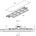
- the follow-up platform 18 is arranged at the platform body 11 and located on one side of the platform body 11, and two ends of the follow-up platform 18 are connected to the front-wheel positioning device 12 and the rear-wheel positioning device 13 respectively. Specifically, the follow-up platform 18 is located between the front-wheel positioning device 12 and the rear-wheel positioning device 13, and is located on the driver's side of the vehicle with a battery to be swapped after it is parked on the platform body 11.
- the follow-up platform 18 comprises a generally elongated first support frame 181 and a first strip-shaped pedal 182 fixedly connected to an upper side of the first support frame 181, and two ends of the first support frame 181 are connected to the front-wheel positioning device 12 and the rear-wheel positioning device 13 respectively. In this way, during the raising process of the vehicle, the follow-up platform 18 rises together with the front-wheel positioning device 12 and the rear-wheel positioning device 13. People in the vehicle on the driver's side can open a vehicle door and get in and out of the vehicle with the help of the follow-up platform 18.
- the follow-up platform 18 By providing the follow-up platform 18, after the vehicle is raised, the follow-up platform 18 can be used as a pedal for getting on and off the vehicle, making it convenient for people in the vehicle to get on and off the vehicle, thereby avoid missing his/her step when getting off the vehicle.
- the two ends of the follow-up platform 18 hingedly connected to the front-wheel positioning device 12 and the rear-wheel positioning device 13 the smoothness of the lifting process of the follow-up platform 18 can be improved, and the jamming can be reduced.
- the height of the platform body 11 (i.e., hi in FIG. 5 ) is less than or equal to 200 mm, and the height of the highest point of the battery swap platform 10 (i.e., h 2 in FIG. 5 ) is less than or equal to 350 mm.
- the height of the platform body 11 is the height that the vehicle needs to rise after reversing into the platform
- the highest point of the battery swap platform 10 is the height at which the top surface of the first connecting frame 162 or the top surface of the second connecting frame 172 is located. It can be seen that the height of the platform body 11 and the overall height of the battery swap platform 10 are each in an extremely low value range, which can undoubtedly provide the user with the ultimate battery swap experience.
- multi-stage hydraulic cylinder in addition to the multi-stage hydraulic cylinder, other retractable devices can also be applied in the disclosure, even if they do not have the effect as prominent as the multi-stage hydraulic cylinder.
- single-stage/multi-stage retractable connecting rods, single-stage/multi-stage retractable frames, single-stage/multi-stage scissor forks, etc. may all replace the multi-stage hydraulic cylinders.
- first jacking components are connected to the first mounting frame 121 via the first connecting portions 16, this connection method is not unique, which may be adjusted by those skilled in the art, as long as each first jacking component is ensured to be connected to one end of the first mounting frame 121.
- the first jacking components may be directly connected to the first mounting frame 121.
- corresponding connecting structures need to be provided at the two ends of the first mounting frame 121.
- the first mounting seat 161 and the first connecting frame 162 of the first connecting portion 16 may be fixedly connected to each other or integrally formed with each other, and then connected to the respective first jacking component and the first mounting frame 121 respectively.
- the connection method between the second jacking components and the second mounting frame 131 may also be adjusted as above.
- the front-wheel positioning device 12 comprises the first mounting frame 121, the front-wheel roller group 122 and the front-wheel centering mechanism 123
- the specific structure of the front-wheel positioning device 12 is not invariable, which may be adjusted by those skilled in the art based on specific application scenarios.
- the first mounting frame 121 of the front-wheel positioning device 12 may be adjusted to other shapes.
- the front-wheel positioning device 12 may only comprise one of the front-wheel roller group 122 and the front-wheel centering mechanism 123, and the other one is arranged at another position of the platform body 11.
- the front-wheel roller group 122 may be interchanged with the I-shaped roller group in addition to the V-shaped roller group.
- those skilled in the art can also make the above adjustments to the specific composition of the rear-wheel positioning device 13.
- first jacking devices 14 and the second jacking devices 15 are explained on the basis that the bottoms thereof being fixedly connected in the first mounting groove 111 and the second mounting groove 112, the specific mounting positions of the two are not unique, and those skilled in the art can also arrange the two on the outer side of the platform body 11 or on the platform body 11 except the mounting grooves, etc. according to requirements.
- the ramp 113 on the platform body 11 is not necessary.
- the provision of the ramp 113 may be omitted, or additional wedge-shaped guide bars may be provided in front of the platform body 11.
- the specific composition of the follow-up platform 18 is not unique. Those skilled in the art can adjust the structure of the follow-up platform 18 as long as it can support people, and this adjustment does not deviate from the principle of the disclosure.
- a battery charging and swapping station of the disclosure is explained below with reference to FIG. 6 .
- the battery charging and swapping station of the disclosure comprises a box 20.
- a battery rack, a battery swap robot, and the battery swap platform 10 according to the above implementations are provided in the box 20.
- the battery rack and the battery swap robot are not shown in FIG. 6 .
- the specific structures of the two are relatively common in the art, and will not be described in detail in the disclosure.
- a battery swap room 21 and a battery charging room 22 are formed in the box 20, the battery swap platform 21 is provided in the battery swap room 10, the battery rack is provided in the battery charging room 22, a partition 23 is provided between the battery swap room 21 and the battery charging room 22, a flip platform 24 is provided on the partition 23, and the flip platform 24 is pivotably connected to the partition 23.
- the flip platform 24 comprises a generally elongated second support frame and a second strip-shaped pedal fixedly connected to one side of the second support frame, there is a gap between the bottom of the partition 23 and the battery swap platform 10, and the top side of the second support frame is pivotably connected to the bottom of the partition 23 when the flip platform 24 is in a vertical state.
- a flip driving device is provided on the partition 23, the flip driving device is connected to the flip platform 24, and the flip driving device is configured to drive the flip platform 24 to pivot from the vertical state to a horizontal state.
- the flip driving device comprises an electric motor and a transmission rod group.
- the electric motor drives the transmission rod group to lift and lower.
- the transmission rod group drives the flip platform 24 to pivot around the pivot axis and switch between the horizontal state and the vertical state.
- the gap between the bottom of the partition 23 and the battery swap platform 10 allows the passage of the battery swap robot.
- the specific composition and structure of the flip platform 24 can be referred to the follow-up platform 18 and will not be described again in the disclosure.
- the battery charging and swapping station of the disclosure adopts the battery swap platform 10 described above, so that it is possible to reduce the space occupied by the jacking devices on the upper side of the battery swap platform 10, while reducing the height of the battery swap platform 10 and improving the user's battery swap experience. Moreover, due to the reduction of the height of the battery swap platform 10 and the reduction of the raising height, the overall height of the battery charging and swapping station can be further reduced, increasing the scope of application of the battery charging and swapping station, making the battery charging and swapping station suitable for height-limited scenarios such as underground garages.
- the flip platform 24 on the partition 23 it is convenient for the people in the vehicle to use the flip platform 24 to get off the vehicle after the vehicle is raised. By providing the flip driving device, the automatic flipping of the flip platform 24 can be realized and the automation degree of the battery swap process can be improved.
- the specific implementation of the battery charging and swapping station is not unique, which may be adjusted by those skilled in the art according to requirements.
- no partition 23 may be provided between the battery swap room 21 and the battery charging room 22, and accordingly the provision of the flip platform 24 is omitted.
- the flip platform 24 may be configured such that in the vertical state, the bottom side of the second support frame is hingedly connected to the bottom side of the partition 23, that is to say, it can be pivoted and deployed from top to bottom when needed.
- no flip driving device may be provided, or the flip driving device may be configured in other ways, as long as it can drive the flip platform 24 to switch between the vertical state and the horizontal state.
- the vehicle with a battery to be swapped is reversed into the platform body 11 until the two rear wheels are supported on the I-shaped roller groups, and the two front wheels are sunk into the V-shaped roller groups, thereby realizing the positioning of the vehicle in the length direction.
- the front-wheel centering mechanism 123 and the rear-wheel centering mechanism 133 are operated to push the front wheels and the rear wheels of the vehicle from the outside of the vehicle until all the external push rods come into contact with the wheels and the thrust reaches a certain threshold, thereby realizing the positioning of the vehicle in the width direction.
- the positioning of the vehicle with a battery to be swapped on the parking platform is completed.
- the four three-stage hydraulic cylinders are extended simultaneously to jack the front-wheel positioning device 12 and the rear-wheel positioning device 13 to raise the vehicle.
- the follow-up platform 18 rises synchronously with the front-wheel positioning device 12 and the rear-wheel positioning device 13.
- the flip driving device is activated to drive the flip platform 24 to pivot from the vertical state to the horizontal state.
- the battery swap robot moves to below the vehicle by means of the track 114 on the platform body 11, disassembles the used battery, transports the used battery back to the battery rack for charging, and then receives a flesh battery from the battery rack.
- the battery swap robot carries the flesh battery back to below the vehicle, mounts the flesh battery to a chassis of the vehicle, and moves out of the chassis of the vehicle.
- the four three-stage hydraulic cylinders are retracted synchronously, to drive the front-wheel positioning device 12 and the rear-wheel positioning device 13 to descend synchronously until they return to their original positions.
- the battery swapping is completed, and the vehicle can exit the battery swap platform 10 after being powered on. If an abnormality occurs during the battery swap process, the people in the vehicle on the driver's side can get out of the vehicle by means of the follow-up platform 18, and the people in the vehicle on the passenger side can get off the vehicle by means of the flip platform 24.
Landscapes
- Engineering & Computer Science (AREA)
- Chemical & Material Sciences (AREA)
- Chemical Kinetics & Catalysis (AREA)
- Electrochemistry (AREA)
- General Chemical & Material Sciences (AREA)
- Transportation (AREA)
- Mechanical Engineering (AREA)
- Aviation & Aerospace Engineering (AREA)
- Manufacturing & Machinery (AREA)
- Combustion & Propulsion (AREA)
- Power Engineering (AREA)
- Arrangement Or Mounting Of Propulsion Units For Vehicles (AREA)
Abstract
The disclosure relates to the technical field of battery charging and swapping, and in particular to a battery swap platform (10) and a battery charging and swapping station. The disclosure aims to solve the problems existing in the lift-type battery charging and swapping station, such as large upper space occupation, limited field of view, and too large platform height. To this end, the battery swap platform (10) of the disclosure comprises: a platform body (11), a first mounting groove (111) and a second mounting groove (112) being formed on and extending in a width direction thereof; a front-wheel positioning device (12) arranged at the first mounting groove (111); a rear-wheel positioning device (13) arranged at the second mounting groove (112); two first jacking devices (14) arranged on two sides of the front-wheel positioning device (12) in the width direction, each device (14) being provided with a retractable first jacking component connected to one end of the front-wheel positioning device (12); and two second jacking devices (15) arranged on two sides of the rear-wheel positioning device (13) in the width direction, each device (15) being provided with a retractable second jacking component connected to one end of the rear-wheel positioning device (13). The disclosure can reduce the space occupied by the jacking devices (14,15), reduce the height of the battery swap platform (10), and improve the user's battery swap experience.
Description
- The present application claims priority of
CN patent application 202310158566.6 filed on February 20, 2023 - The disclosure relates to the technical field of battery charging and swapping, and in particular to a battery swap platform and a battery charging and swapping station.
- In recent years, as the number of new energy vehicles has increased year by year, how to quickly and effectively replenish energy for new energy vehicles in a drained state has become a matter of great concern to many users and manufacturers. Currently, there are two main technical solutions for new energy replenishment: battery charging and swapping. Compared with the battery charging solution, the battery swapping solution has become an important development direction for energy replenishment due to its advantages such as shorter time and less damage to the battery.
- Battery swapping is usually carried out in a battery swap station. There are mainly lift-type, stage-type (the battery swap platform is raised as a whole to accommodate a battery swap robot), and dug-in type (a pit is dug below the battery swap platform to accommodate a battery swap robot) battery swap stations on the market. Compared with the other two types of battery swap stations, the lift-type battery swap station has relatively low requirements for site selection, infrastructure, transportation, etc., which is conducive to product promotion. However, it also has certain shortcomings. In some lift-type battery swap solutions, due to the existence of lifting columns, a relatively large space is occupied on the upper side of the battery swap platform, resulting in limited field of view of a user. Moreover, the height of the vehicle raised by the lifting columns is relatively large, making it inconvenient for the user to get off the vehicle and resulting in a poor battery swap experience. In some other lift-type battery swap solutions, lifting devices are arranged under wheel positioning devices to lift the vehicle by lifting wheels. However, in this way, the lifting devices excessively occupy the space under the battery swap platform, resulting in increased overall height of the battery swap platform, so that the driving of the vehicle into the battery swap platform is not facilitated, and the battery swap experience is poor.
- Accordingly, there is a need for a new technical solution in the field to solve the problem described above.
- In order to solve at least one of the aforementioned problems in the prior art, that is, in order to solve the problems of a large space occupied on the upper side of the platform, limited field of view, and inconvenience in getting off the vehicle due to the use of lifting columns in the lift-type battery charging and swapping station, and the problem of not facilitating vehicle entry caused by excessive increase in the height of the platform due to the provision of the lifting devices under the wheel positioning devices, in a first aspect of the disclosure, provided is a battery swap platform, comprising:
- a platform body, a first mounting groove and a second mounting groove being formed on the platform body and extending in a width direction thereof;
- a front-wheel positioning device arranged at the first mounting groove;
- a rear-wheel positioning device arranged at the second mounting groove;
- two first jacking devices arranged on two sides of the front-wheel positioning device in the width direction, the first jacking devices having retractable first jacking components, and each first jacking component is connected to one end of the front-wheel positioning device; and
- two second jacking devices arranged on two sides of the rear-wheel positioning device in the width direction, the second jacking devices having retractable second jacking components, and each second jacking component being connected to one end of the rear-wheel positioning device.
- In the technical solution of the disclosure, by providing the first jacking devices and the second jacking devices, it is possible to significantly reduce the height of the battery swap platform while reducing the space occupied by the jacking devices on the platform, and to significantly improve the user's battery swap experience. Specifically, the first jacking devices have retractable first jacking components, and the second jacking devices have retractable second jacking components, so that the first jacking components and the second jacking components can provide sufficient jacking height when extended, so as to facilitate battery swapping for a vehicle with a battery to be swapped. Moreover, the first jacking components and the second jacking components can maintain a low enough height when retracted, avoiding the occupation of too much space on the upper side of the battery swap platform which otherwise results in limited field of view of the user. Furthermore, since the objects jacked by the first jacking devices and the second jacking devices are the front-wheel positioning device and the rear-wheel positioning device, the raised height of the vehicle can be reduced, the battery swap operation can be completed only by lifting the vehicle to a very low height, and the restrictions on the design of a vehicle body can also be reduced. In addition, since the first jacking devices and the second jacking devices are arranged on two sides of the front-wheel positioning device and the rear-wheel positioning device in the width direction of the platform, there is no need to occupy the space under the front-wheel positioning device and the rear-wheel positioning device, so that the height of the platform body can be also greatly reduced, facilitating the more convenient and smoother entry of the vehicle into the battery swap platform, and improving the user's battery swap experience.
- In a preferred technical solution of the battery swap platform described above, the front-wheel positioning device comprises a first mounting frame and a front-wheel roller group, the first mounting frame is embedded in the first mounting groove, the front-wheel roller group is mounted in the first mounting frame, and each first jacking component is connected to one end of the first mounting frame.
- By providing the first mounting frame, the mounting accuracy of the front-wheel roller group can be improved, the mounting error can be reduced, and the stability of the raising process can also be improved.
- In a preferred technical solution of the battery swap platform described above, the battery swap platform further comprises first connecting portions, via which the first jacking components are connected to the first mounting frame.
- By providing the first connecting portions, the difficulty of designing and manufacturing the front-wheel positioning device can be reduced, the connection accuracy can be ensured, and the manufacturing cost can be saved.
- In a preferred technical solution of the battery swap platform described above, the first connecting portions each comprise a first mounting seat and a first connecting frame, the first mounting seat is fixedly connected to an end portion of the first mounting frame, the first connecting member is located on an upper side of the first mounting seat and is hingedly connected to the first mounting seat, an outwardly extending first mounting stiffener is formed on the first connecting frame, and the respective first jacking component is connected to the first mounting stiffener.
- Through the hinged connection between the first mounting seat and the first connecting frame, the smoothness of the raising process can be improved and the jamming of the raising process can be reduced.
- In a preferred technical solution of the battery swap platform described above, the front-wheel roller group is a V-shaped roller group.
- In a preferred technical solution of the battery swap platform described above, the front-wheel positioning device further comprises a front-wheel centering mechanism mounted in the first mounting frame.
- By arranging the front-wheel centering mechanism in the first mounting frame, the integrity of the front-wheel positioning device can be improved, and the battery swap accuracy can be improved.
- In a preferred technical solution of the battery swap platform described above, the rear-wheel positioning device comprises a second mounting frame and a rear-wheel roller group, the second mounting frame is embedded in the second mounting groove, the rear-wheel roller group is mounted in the second mounting frame, and each second jacking component is connected to one end of the second mounting frame.
- By providing the second mounting frame, the mounting accuracy of the rear-wheel roller group can be improved, the mounting error can be reduced, and the stability of the raising process can also be improved.
- In a preferred technical solution of the battery swap platform described above, the battery swap platform further comprises second connecting portions, via which the second jacking components are connected to the second mounting frame.
- By providing the second connecting portions, the difficulty of designing and manufacturing the rear-wheel positioning device can be reduced, the connection accuracy can be ensured, and the manufacturing cost can be saved.
- In a preferred technical solution of the battery swap platform described above, the second connecting portions each comprise a second mounting seat and a second connecting frame, the second mounting seat is fixedly connected to an end portion of the second mounting frame, the second connecting member is located on an upper side of the second mounting seat and is hingedly connected to the second mounting seat, an outwardly extending second mounting stiffener is formed on the second connecting frame, and the respective second jacking component is connected to the second mounting stiffener.
- Through the hinged connection between the second mounting seat and the second connecting frame, the smoothness of the raising process can be improved and the jamming of the raising process can be reduced.
- In a preferred technical solution of the battery swap platform described above, the rear-wheel roller group is an I-shaped roller group.
- In a preferred technical solution of the battery swap platform described above, the rear-wheel positioning device further comprises a rear-wheel centering mechanism mounted in the second mounting frame.
- By arranging the rear-wheel centering mechanism in the second mounting frame, the integrity of the rear-wheel positioning device can be improved, and the battery swap accuracy can be improved.
- In a preferred technical solution of the battery swap platform described above, the bottom of each first jacking device is fixedly connected to the first mounting groove; and/or
the bottom of each second jacking device is fixedly connected to the second mounting groove. - By having the bottom of each first jacking device fixedly connected to the first mounting groove, the height space occupied by the first jacking device can be further reduced, and the flatness of the battery swap platform can be ensured. By having the bottom of each second jacking device fixedly connected to the second mounting groove, the height space occupied by the second jacking device can be further reduced, and the flatness of the battery swap platform can be ensured.
- In a preferred technical solution of the battery swap platform described above, the first jacking components and the second jacking components are multi-stage jacking components.
- By configuring the first jacking components and the second jacking components as multi-stage jacking components, the height space occupied by the first jacking components and the second jacking components can be reduced to the greatest extent, which is conducive to providing a user with the ultimate battery swap experience.
- In a preferred technical solution of the battery swap platform described above, the first jacking devices and/or the second jacking devices are multi-stage hydraulic cylinders, multi-stage pneumatic cylinders or multi-stage electric cylinders; and/or
the first jacking components and/or the second jacking components have three or four stages. - In a preferred technical solution of the battery swap platform described above, the height of the platform body is less than or equal to 200 mm.
- In a preferred technical solution of the battery swap platform described above, a ramp is formed at one end of the platform body in a length direction.
- By providing a ramp at one end of the platform body, the vehicle can be guided into the battery swap platform, further improving the convenience of the vehicle entering the platform.
- In a preferred technical solution of the battery swap platform described above, the battery swap platform further comprises a follow-up platform, wherein the follow-up platform is arranged at the platform body and located on one side of the platform body, and two ends of the follow-up platform are connected to the front-wheel positioning device and the rear-wheel positioning device respectively.
- By providing the follow-up platform, after the vehicle is raised, the follow-up platform can be used as a pedal for getting on and off the vehicle, making it convenient for people in the vehicle to get on and off the vehicle, thereby avoid missing his/her step when getting off the vehicle.
- In a preferred technical solution of the battery swap platform described above, the two ends of the follow-up platform are hingedly connected to the front-wheel positioning device and the rear-wheel positioning device respectively.
- By having the two ends of the follow-up platform hingedly connected to the front-wheel positioning device and the rear-wheel positioning device, the smoothness of the lifting process of the follow-up platform can be improved, and the jamming can be reduced.
- In a preferred technical solution of the battery swap platform described above, the follow-up platform comprises a generally elongated first support frame and a first strip-shaped pedal fixedly connected to an upper side of the first support frame, and two ends of the first support frame are connected to the front-wheel positioning device and the rear-wheel positioning device respectively.
- In a second aspect of the disclosure, further provided is a battery charging and swapping station, comprising a box, wherein a battery rack, a battery swap robot, and a battery swap platform according to any item of the first aspect are provided in the box.
- The battery charging and swapping station of the disclosure adopts the battery swap platform described above, so that it is possible to reduce the space occupied by the jacking devices on the upper side of the battery swap platform, while reducing the height of the battery swap platform and improving the user's battery swap experience. Moreover, due to the reduction of the height of the battery swap platform and the reduction of the raising height, the overall height of the battery charging and swapping station can be further reduced, increasing the scope of application of the battery charging and swapping station, making the battery charging and swapping station suitable for height-limited scenarios such as underground garages.
- In a preferred technical solution of the battery charging and swapping station described above, a battery swap room and a battery charging room are formed in the box, the battery swap platform is provided in the battery swap room, the battery rack is provided in the battery charging room, a partition is provided between the battery swap room and the battery charging room, a flip platform is provided on the partition, and the flip platform is pivotably connected to the partition.
- By providing the flip platform on the partition, it is convenient for the people in the vehicle to use the flip platform to get off the vehicle after the vehicle is raised.
- In a preferred technical solution of the battery charging and swapping station described above, a flip driving device is provided on the partition, the flip driving device is connected to the flip platform, and the flip driving device is configured to drive the flip platform to pivot from a vertical state to a horizontal state.
- By providing the flip driving device, the automatic flipping of the flip platform can be realized and the automation degree of the battery swap process can be improved.
- In a preferred technical solution of the battery charging and swapping station described above, there is a gap between the bottom of the partition and the battery swap platform, and a top side of the flip platform in the vertical state is pivotably connected to the bottom of the partition.
- In a preferred technical solution of the battery charging and swapping station described above, the flip platform comprises a generally elongated second support frame and a second strip-shaped pedal fixedly connected to one side of the second support frame, and the second support frame is pivotably connected to the partition.
- Solution 1. A battery swap platform, comprising:
- a platform body, a first mounting groove and a second mounting groove being formed on the platform body and extending in a width direction thereof;
- a front-wheel positioning device arranged at the first mounting groove;
- a rear-wheel positioning device arranged at the second mounting groove;
- two first jacking devices arranged on two sides of the front-wheel positioning device in the width direction, the first jacking devices having retractable first jacking components, and each first jacking component is connected to one end of the front-wheel positioning device; and
- two second jacking devices arranged on two sides of the rear-wheel positioning device in the width direction, the second jacking devices having retractable second jacking components, and each second jacking component being connected to one end of the rear-wheel positioning device.
- Solution 2. The battery swap platform according to solution 1, wherein the front-wheel positioning device comprises a first and a front-wheel roller group, the first mounting frame is embedded in the first mounting groove, the front-wheel roller group is mounted in the first mounting frame, and each first jacking component is connected to one end of the first mounting frame.
- Solution 3. The battery swap platform according to solution 2, further comprising first connecting portions, via which the first jacking components are connected to the first mounting frame.
- Solution 4. The battery swap platform according to solution 3, wherein the first connecting portions each comprise a first mounting seat and a first connecting frame, the first mounting seat is fixedly connected to an end portion of the first mounting frame, the first connecting member is located on an upper side of the first mounting seat and is hingedly connected to the first mounting seat, an outwardly extending first mounting stiffener is formed on the first connecting frame, and the respective first jacking component is connected to the first mounting stiffener.
- Solution 5. The battery swap platform according to solution 2, wherein the front-wheel roller group is a V-shaped roller group.
- Solution 6. The battery swap platform according to solution 2, wherein the front-wheel positioning device further comprises a front-wheel centering mechanism mounted in the first mounting frame.
- Solution 7. The battery swap platform according to solution 1, wherein the rear-wheel positioning device comprises a second mounting frame and a rear-wheel roller group, the second mounting frame is embedded in the second mounting groove, the rear-wheel roller group is mounted in the second mounting frame, and each second jacking component is connected to one end of the second mounting frame.
- Solution 8. The battery swap platform according to solution 7, further comprising second connecting portions, via which the second jacking components are connected to the second mounting frame.
- Solution 9. The battery swap platform according to solution 8, wherein the second connecting portions each comprise a second mounting seat and a second connecting frame, the second mounting seat is fixedly connected to an end portion of the second mounting frame, the second connecting member is located on an upper side of the second mounting seat and is hingedly connected to the second mounting seat, an outwardly extending second mounting stiffener is formed on the second connecting frame, and the respective second jacking component is connected to the second mounting stiffener.
-
Solution 10. The battery swap platform according to solution 7, wherein the rear-wheel roller group is an I-shaped roller group. -
Solution 11. The battery swap platform according to solution 7, wherein the rear-wheel positioning device further comprises a rear-wheel centering mechanism mounted in the second mounting frame. -
Solution 12. The battery swap platform according to solution 1, wherein the bottom of each first jacking device is fixedly connected to the first mounting groove; and/or
the bottom of each second jacking device is fixedly connected to the second mounting groove. -
Solution 13. The battery swap platform according to solution 1, wherein the first jacking components and the second jacking components are multi-stage jacking components. -
Solution 14. The battery swap platform according tosolution 13, wherein the first jacking devices and/or the second jacking devices are multi-stage hydraulic cylinders, multi-stage pneumatic cylinders or multi-stage electric cylinders; and/or
the first jacking components and/or the second jacking components have three or four stages. -
Solution 15. The battery swap platform according to solution 1, wherein the height of the platform body is less than or equal to 200 mm. -
Solution 16. The battery swap platform according to solution 1, wherein a ramp is formed at one end of the platform body in a length direction. -
Solution 17. The battery swap platform according to any one of Solutions 1 to 16, further comprising a follow-up platform, wherein the follow-up platform is arranged at the platform body and located on one side of the platform body, and two ends of the follow-up platform are connected to the front-wheel positioning device and the rear-wheel positioning device respectively. -
Solution 18. The battery swap platform according tosolution 17, wherein the two ends of the follow-up platform are hingedly connected to the front-wheel positioning device and the rear-wheel positioning device respectively. - Solution 19. The battery swap platform according to
solution 17, wherein the follow-up platform comprises a generally elongated first support frame and a first strip-shaped pedal fixedly connected to an upper side of the first support frame, and two ends of the first support frame are connected to the front-wheel positioning device and the rear-wheel positioning device respectively. -
Solution 20. A battery charging and swapping station, comprising a box, wherein a battery rack, a battery swap robot, and a battery swap platform of any one of Solutions 1 to 19 are provided in the box. -
Solution 21. The battery charging and swapping station according tosolution 20, wherein a battery swap room and a battery charging room are formed in the box, the battery swap platform is provided in the battery swap room, the battery rack is provided in the battery charging room, a partition is provided between the battery swap room and the battery charging room, a flip platform is provided on the partition, and the flip platform is pivotably connected to the partition. -
Solution 22. The battery charging and swapping station according tosolution 21, wherein a flip driving device is provided on the partition, the flip driving device is connected to the flip platform, and the flip driving device is configured to drive the flip platform to pivot from a vertical state to a horizontal state. - Solution 23. The battery charging and swapping station according to
solution 21, wherein there is a gap between the bottom of the partition and the battery swap platform, and a top side of the flip platform in the vertical state is pivotably connected to the bottom of the partition. -
Solution 24. The battery charging and swapping station according tosolution 21, wherein the flip platform comprises a generally elongated second support frame and a second strip-shaped pedal fixedly connected to one side of the second support frame, and the second support frame is pivotably connected to the partition. - The disclosure will be described below with reference to the accompanying drawings. In the drawings:
-
FIG. 1 is an assembly diagram of a battery swap platform according to the disclosure; -
FIG. 2 is a partially exploded view of a battery swap platform according to the disclosure; -
FIG. 3 is an exploded view of a front-wheel positioning device, a rear-wheel positioning device, first jacking devices and second jacking devices according to the disclosure; -
FIG. 4 is an exploded view of a follow-up platform according to the disclosure; -
FIG. 5 is a partial side view of a battery swap platform according to the disclosure; and -
FIG. 6 is an assembly diagram of a battery charging and swapping station according to the disclosure. -
- 10. Battery swap platform; 11. Platform body; 111. First mounting groove; 112. Second mounting groove; 113. Ramp; 114. Track; 12. Front-wheel positioning device; 121. First mounting frame; 122. Front-wheel roller group; 123. Front-wheel centering mechanism; 13. Rear-wheel positioning device; 131. Second mounting frame; 132. Rear-wheel roller group; 133. Rear-wheel centering mechanism; 14. First jacking device; 15. Second jacking device; 16. First connecting portion; 161. First mounting seat; 162. First connecting frame; 1621. First mounting stiffener; 17. Second connecting portion; 171. Second mounting seat; 172. Second connecting frame; 1721. Second mounting stiffener; 18. Follow-up platform; 181. First support frame; 182. First strip-shaped pedal;
- 20. Box; 21. Battery swap room; 22. Battery charging room; 23. Partition; 24. Flip platform.
- Preferred implementations of the disclosure are described below with reference to the accompanying drawings. Those skilled in the art should understand that these implementations are only used to explain the technical principles of the disclosure, and are not intended to limit the scope of protection of the disclosure.
- It should be noted that in the description of the disclosure, the terms, such as "upper", "lower", "vertical", "horizontal", "inner" and "outer" that indicate directions or positional relationships, are based on the directions or positional relationships shown in the accompanying drawings only for convenience of description, do not indicate or imply that the apparatus or element must have a specific orientation or be constructed and operated in a specific orientation, and therefore cannot be construed as limitation to the disclosure. In addition, the terms "first" and "second" are used for descriptive purposes only, and cannot be construed as indicating or implying relative importance. In addition, the length direction of a platform body described in the following implementations of the disclosure is the length direction of a vehicle with a battery to be swapped when the vehicle is parked on a battery swap platform, and the width direction of the platform body is the width direction of a vehicle with a battery to be swapped when the vehicle is parked on the battery swap platform.
- In addition, it should also be noted that in the description of the disclosure, the terms "mount", "connected to each other" and "connection" should be interpreted in a broad sense unless explicitly defined and limited otherwise. For example, a connection may be a fixed connection, a detachable connection or an integral connection; may be a mechanical connection or an electrical connection; and or may be a direct connection, an indirect connection by means of an intermediary, or internal communication between two elements. Those skilled in the art can understand specific meanings of the above terms in the disclosure according to specific situations.
- First, a battery swap platform in the disclosure is described with reference to
FIGS. 1 and 2 . - As shown in
FIGS. 1 and 2 , in order to solve the problems of a large space occupied on the upper side of the platform, limited field of view, and inconvenience in getting off the vehicle due to the use of lifting columns in the lift-type battery charging and swapping station, and the problem of not facilitating vehicle entry caused by excessive increase in the height of the platform due to the provision of the lifting devices under the wheel positioning devices, abattery swap platform 10 of the disclosure comprises: aplatform body 11, a front-wheel positioning device 12, a rear-wheel positioning device 13, two first jackingdevices 14, and two second jackingdevices 15. A first mountinggroove 111 and asecond mounting groove 112 are formed on theplatform body 11 and extend in a width direction thereof. The front-wheel positioning device 12 is arranged at the first mountinggroove 111 for positioning front wheels of a vehicle with a battery to be swapped (hereinafter referred to as vehicle) during a battery swap process, and the rear-wheel positioning device 13 is arranged at the second mountinggroove 112 for positioning rear wheels of the vehicle with a battery to be swapped during the battery swap process. The two first jackingdevices 14 are arranged on two sides of the front-wheel positioning device 12 in the width direction of theplatform body 11. Each first jackingdevice 14 has a retractable first jacking component, and each first jacking component is connected to one end of the front-wheel positioning device 12. The two second jackingdevices 15 are arranged on two sides of the rear-wheel positioning device 13 in the width direction of theplatform body 11. Each second jackingdevice 15 has a retractable second jacking component, and each second jacking component is connected to one end of the rear-wheel positioning device 13. - In a possible implementation process, before the battery swapping begins, the vehicle with a battery to be swapped enters the
battery swap platform 10 and stops on theplatform body 11, and the two front wheels of the vehicle with a battery to be swapped are located at the front-wheel positioning device 12, and the two rear wheels are located at the rear-wheel positioning device 13. After the battery swapping starts, the two first jackingdevices 14 and the two second jackingdevices 15 are operated synchronously, and the first jacking components and the second jacking components are synchronously extended to jack the front-wheel positioning device 12 and the rear-wheel positioning device 13 to a certain height so that the vehicle with a battery to be swapped is lifted. A battery swap robot then moves to the bottom of the vehicle with a battery to be swapped to remove the used battery, and then swaps a flesh battery and mounts the flesh battery to the bottom of the vehicle. After the mounting is completed, the battery swap robot moves out of the bottom of the vehicle, the two first jackingdevices 14 and the two second jackingdevices 15 are operated synchronously, and the first jacking components and the second jacking components are retracted synchronously, to drive the front-wheel positioning device 12 and the rear-wheel positioning device 13 to return to their original positions. At this time, the battery swapping is completed, and the vehicle can exit thebattery swap platform 10 after being powered on. - In the technical solution of the disclosure, by providing the first jacking
devices 14 and the second jackingdevices 15, it is possible to significantly reduce the height of thebattery swap platform 10 while reducing the space occupied by the jacking devices on the platform, and to significantly improve the user's battery swap experience. Specifically, the first jackingdevices 14 have retractable first jacking components, and the second jackingdevices 15 have retractable second jacking components, so that the first jacking components and the second jacking components can provide sufficient jacking height when extended, so as to facilitate battery swapping for a vehicle with a battery to be swapped. Moreover, the first jacking components and the second jacking components can maintain a low enough height when retracted, avoiding the occupation of too much space on the upper side of thebattery swap platform 10 which otherwise results in limited field of view of the user. Furthermore, since the objects jacked by the first jackingdevices 14 and the second jackingdevices 15 are the front-wheel positioning device 12 and the rear-wheel positioning device 13, the raised height of the vehicle can be reduced, the battery swap operation can be completed only by lifting the vehicle to a very low height, and the restrictions on the design of a vehicle body can also be reduced. In addition, since the first jackingdevices 14 and the second jackingdevices 15 are arranged on two sides of the front-wheel positioning device 12 and the rear-wheel positioning device 13 in the width direction of the platform, there is no need to occupy the space under the front-wheel positioning device 12 and the rear-wheel positioning device 13, so that the height of theplatform body 11 can be also greatly reduced, facilitating the more convenient and smoother entry of the vehicle into thebattery swap platform 10, and improving the user's battery swap experience. - A preferred implementation of the
battery swap platform 10 of the disclosure is explained below with reference toFIGS. 1 to 5 . - As shown in
FIGS. 1 to 5 , in a preferred implementation, thebattery swap platform 10 comprises aplatform body 11, a front-wheel positioning device 12, a rear-wheel positioning device 13, two first jackingdevices 14, two second jackingdevices 15, and a follow-upplatform 18. - As shown in
FIGS. 1 and 2 , theplatform body 11 is constructed of a frame, on which a first mountinggroove 111 and asecond mounting groove 112 are provided. Thefirst mounting groove 111 and the second mountinggroove 112 are arranged back and forth in the length direction of theplatform body 11, and the first mountinggroove 111 and the second mountinggroove 112 both extend in the width direction of theplatform body 11. Thefirst mounting groove 111 is used to accommodate the front-wheel positioning device 12, and the second mountinggroove 112 is used to accommodate the rear-wheel positioning device 13. Aramp 113 is formed at one end of theplatform body 11 that is close to the first mountinggroove 111. During battery swapping, the vehicle with a battery to be swapped is reversed into thebattery swap platform 10 under the guidance of theramp 113. After driving in place, the front wheels of the vehicle are located at the front-wheel positioning device 12, and the rear wheels are located at the rear-wheel positioning device 13. Atrack 114 for the battery swap robot to enter and exit is further formed on the upper side of theplatform body 11. Thetrack 114 extends in the width direction of theplatform body 11. After the vehicle is raised, the battery swap robot moves to below the vehicle by means of thetrack 114, to remove the used battery and mount a flesh battery. - By providing a
ramp 113 at one end of theplatform body 11, the vehicle can be guided into thebattery swap platform 10, further improving the convenience of the vehicle entering the platform. - Referring to
FIGS. 2 and3 , the front-wheel positioning device 12 comprises afirst mounting frame 121, a front-wheel roller group 122 and a front-wheel centering mechanism 123. Thefirst mounting frame 121 is embedded in the first mountinggroove 111, and has an open upper side and a substantially C-shaped cross-section. The front-wheel roller group 122 and the front-wheel centering mechanism 123 are both mounted in thefirst mounting frame 121. The front-wheel roller group 122 is a V-shaped roller group. Two V-shaped roller groups are provided, and they are fixedly connected to the inner sides of two ends of thefirst mounting frame 121. The front-wheel centering mechanism 123 is fixedly mounted in thefirst mounting frame 121 and is mostly located below the V-shaped roller group. In the disclosure, the front-wheel centering mechanism 123 takes the form of an external push rod mechanism. Two external push rod mechanisms are provided, and they are symmetrically arranged in thefirst mounting frame 121. After the arrangement is completed, push rods extend to above the V-shaped roller groups. During operation, an electric motor drives the external push rods to move from two ends to the middle by means of a transmission assembly. During the movement, the external push rods abut against the outer sides of the front wheels of the vehicle with a battery to be swapped and pushes the vehicle to move centrally. - The rear-
wheel positioning device 13 comprises asecond mounting frame 131, a rear-wheel roller group 132 and a rear-wheel centering mechanism 133. Thesecond mounting frame 131 is embedded in the second mountinggroove 112, and has an open upper side and a substantially C-shaped cross-section. The rear-wheel roller group 132 and the rear-wheel centering mechanism 133 are both mounted in thesecond mounting frame 131. The rear-wheel roller group 132 is an I-shaped roller group. Two I-shaped roller groups are provided, and they are fixedly connected to the inner sides of two ends of thesecond mounting frame 131. The rear-wheel centering mechanism 133 is fixedly mounted in thesecond mounting frame 131 and is mostly located below the I-shaped roller group. In the disclosure, the rear-wheel centering mechanism 133 takes the form of an external push rod mechanism. Two external push rod mechanisms are provided, and they are symmetrically arranged in thesecond mounting frame 131. After the arrangement is completed, push rods extend to above the I-shaped roller groups. During operation, an electric motor drives the external push rods to move from two ends to the middle by means of a transmission assembly. During the movement, the external push rods abut against the outer sides of the rear wheels of the vehicle with a battery to be swapped and pushes the vehicle to move centrally. It should be noted that the specific structural forms of the V-shaped roller group, the I-shaped roller group, the front-wheel centering mechanism 123 and the rear-wheel centering mechanism 133 are common structures in the art and will not be described in detail here. - By providing the
first mounting frame 121, the mounting accuracy of the front-wheel roller group 122 can be improved, the mounting error can be reduced, and the stability of the raising process can also be improved. By arranging the front-wheel centering mechanism 123 in thefirst mounting frame 121, the integrity of the front-wheel positioning device 12 can be improved, and the battery swap accuracy can be improved. By providing thesecond mounting frame 131, the mounting accuracy of the rear-wheel roller group 132 can be improved, the mounting error can be reduced, and the stability of the raising process can also be improved. By arranging the rear-wheel centering mechanism 133 in thesecond mounting frame 131, the integrity of the rear-wheel positioning device 13 can be improved, and the battery swap accuracy can be improved. - Still referring to
FIGS. 2 and3 , the bottom of each first jackingdevice 14 is fixedly connected to an end portion of the first mountinggroove 111, and the first jacking component of the first jackingdevice 14 is connected to thefirst mounting frame 121 via a first connectingportion 16. Similarly, the bottom of each second jackingdevice 15 is fixedly connected to an end portion of the second mountinggroove 112, and the second jacking component is connected to thesecond mounting frame 131 via a second connectingportion 17. The specific connection methods of the first jackingdevices 14 and the second jackingdevices 15 are not limited in the disclosure, as long as the two can be effectively fixed. For example, screwing, welding, riveting, etc. may be used to fix the first jackingdevices 14 and the second jackingdevices 15. - Preferably, in the disclosure, the first jacking
devices 14 and the second jackingdevices 15 both use multi-stage hydraulic cylinders, and the first jacking components and the second jacking components both have three stages. The multi-stage hydraulic cylinder comprises a cylinder body and a multi-stage socketed piston rod (i.e., jacking component) arranged in the cylinder body. By controlling the direction of hydraulic oil in and out of the cylinder body, the multi-stage piston rod can be extended or retracted stage by stage. The specific structure of the multi-stage hydraulic cylinder is relatively common and will not be described in detail in the disclosure. The following section of the disclosure will focus on the structural connection method of the multi-stage hydraulic cylinder and thebattery swap platform 10. - Referring to
FIG. 3 , the first connectingportions 16 each comprise a first mountingseat 161 and a first connectingframe 162. The first mountingseat 161 is screwed and fixedly connected to an end portion of thefirst mounting frame 121, the first connecting member is located on an upper side of the first mountingseat 161 and is hingedly connected to the first mountingseat 161, an outwardly extending first mountingstiffener 1621 is formed on the first connectingframe 162, and the respective first jacking component is connected to thefirst mounting stiffener 1621. Similarly, the second connectingportions 17 each comprise a second mountingseat 171 and a second connectingframe 172. The second mountingseat 171 is fixedly connected to an end portion of thesecond mounting frame 131, the second connecting member is located on an upper side of the second mountingseat 171 and is hingedly connected to the second mountingseat 171, an outwardly extendingsecond mounting stiffener 1721 is formed on the second connectingframe 172, and the respective second jacking component is connected to thesecond mounting stiffener 1721. The specific connection methods of the first jacking component and thefirst mounting stiffener 1621, and the second jacking component and thesecond mounting stiffener 1721 are not limited in the disclosure, which may be screwing, flanged connection, riveting, etc. - By providing the first connecting
portions 16, the difficulty of designing and manufacturing the front-wheel positioning device 12 can be reduced, the connection accuracy can be ensured, and the manufacturing cost can be saved. Through the hinged connection between the first mountingseat 161 and the first connectingframe 162, the smoothness of the raising process can be improved and the jamming of the raising process can be reduced. By providing the second connectingportions 17, the difficulty of designing and manufacturing the rear-wheel positioning device 13 can be reduced, the connection accuracy can be ensured, and the manufacturing cost can be saved. Through the hinged connection between the second mountingseat 171 and the second connectingframe 172, the smoothness of the raising process can be improved and the jamming of the raising process can be reduced. By having the bottom of each first jackingdevice 14 fixedly connected to the first mountinggroove 111, the height space occupied by the first jackingdevice 14 can be further reduced, and the flatness of thebattery swap platform 10 can be ensured. By having the bottom of each second jackingdevice 15 fixedly connected to the second mountinggroove 112, the height space occupied by the second jackingdevice 15 can be further reduced, and the flatness of thebattery swap platform 10 can be ensured. By configuring the first jacking components and the second jacking components as multi-stage jacking components, the height space occupied by the first jacking components and the second jacking components can be reduced to the greatest extent, which is conducive to providing a user with the ultimate battery swap experience. By using multi-stage hydraulic cylinders for the first jackingdevices 14 and the second jackingdevices 15, the structural complexity of the devices can be reduced while ensuring the jacking stability. - Referring to
FIGS 2 and4 , the follow-upplatform 18 is arranged at theplatform body 11 and located on one side of theplatform body 11, and two ends of the follow-upplatform 18 are connected to the front-wheel positioning device 12 and the rear-wheel positioning device 13 respectively. Specifically, the follow-upplatform 18 is located between the front-wheel positioning device 12 and the rear-wheel positioning device 13, and is located on the driver's side of the vehicle with a battery to be swapped after it is parked on theplatform body 11. The follow-upplatform 18 comprises a generally elongatedfirst support frame 181 and a first strip-shapedpedal 182 fixedly connected to an upper side of thefirst support frame 181, and two ends of thefirst support frame 181 are connected to the front-wheel positioning device 12 and the rear-wheel positioning device 13 respectively. In this way, during the raising process of the vehicle, the follow-upplatform 18 rises together with the front-wheel positioning device 12 and the rear-wheel positioning device 13. People in the vehicle on the driver's side can open a vehicle door and get in and out of the vehicle with the help of the follow-upplatform 18. - By providing the follow-up
platform 18, after the vehicle is raised, the follow-upplatform 18 can be used as a pedal for getting on and off the vehicle, making it convenient for people in the vehicle to get on and off the vehicle, thereby avoid missing his/her step when getting off the vehicle. By having the two ends of the follow-upplatform 18 hingedly connected to the front-wheel positioning device 12 and the rear-wheel positioning device 13, the smoothness of the lifting process of the follow-upplatform 18 can be improved, and the jamming can be reduced. - Referring to
FIG. 5 , after the above arrangement is completed, the height of the platform body 11 (i.e., hi inFIG. 5 ) is less than or equal to 200 mm, and the height of the highest point of the battery swap platform 10 (i.e., h2 inFIG. 5 ) is less than or equal to 350 mm. In the disclosure, the height of theplatform body 11 is the height that the vehicle needs to rise after reversing into the platform, and the highest point of thebattery swap platform 10 is the height at which the top surface of the first connectingframe 162 or the top surface of the second connectingframe 172 is located. It can be seen that the height of theplatform body 11 and the overall height of thebattery swap platform 10 are each in an extremely low value range, which can undoubtedly provide the user with the ultimate battery swap experience. - It should be noted that the above preferred implementations are merely used for illustrating the principles of the disclosure, and are not intended to limit the scope of protection of the disclosure. Those skilled in the art can adjust the above configuration without departing from the principles of the disclosure, such that the disclosure can be applicable to more specific application scenarios.
- For example, although the above implementations are explained with the first jacking
devices 14 and the second jackingdevices 15 being three-stage hydraulic cylinders as an example, the arrangement of the two is not restrictive, which may be adjusted by those skilled in the art based on specific application scenarios. For example, at least one of the two may be replaced by a pneumatic cylinder or an electric cylinder, and the first jacking components and/or the second jacking components may have one, two, four or more stages. Of course, fewer stages means that the device occupies a larger height, and more stages means a more complex structure. The disclosure uses a three-stage hydraulic cylinder, which can take into account both space occupation and structural complexity. - In addition, those skilled in the art can also understand that in addition to the multi-stage hydraulic cylinder, other retractable devices can also be applied in the disclosure, even if they do not have the effect as prominent as the multi-stage hydraulic cylinder. For example, single-stage/multi-stage retractable connecting rods, single-stage/multi-stage retractable frames, single-stage/multi-stage scissor forks, etc. may all replace the multi-stage hydraulic cylinders.
- For another example, although the above implementations are explained on the basis that the first jacking components are connected to the
first mounting frame 121 via the first connectingportions 16, this connection method is not unique, which may be adjusted by those skilled in the art, as long as each first jacking component is ensured to be connected to one end of thefirst mounting frame 121. For example, the first jacking components may be directly connected to thefirst mounting frame 121. In this case, corresponding connecting structures need to be provided at the two ends of thefirst mounting frame 121. For another example, the first mountingseat 161 and the first connectingframe 162 of the first connectingportion 16 may be fixedly connected to each other or integrally formed with each other, and then connected to the respective first jacking component and thefirst mounting frame 121 respectively. Similarly, the connection method between the second jacking components and thesecond mounting frame 131 may also be adjusted as above. - For another example, although the above implementations are explained on the basis that the front-
wheel positioning device 12 comprises thefirst mounting frame 121, the front-wheel roller group 122 and the front-wheel centering mechanism 123, the specific structure of the front-wheel positioning device 12 is not invariable, which may be adjusted by those skilled in the art based on specific application scenarios. For example, thefirst mounting frame 121 of the front-wheel positioning device 12 may be adjusted to other shapes. For another example, the front-wheel positioning device 12 may only comprise one of the front-wheel roller group 122 and the front-wheel centering mechanism 123, and the other one is arranged at another position of theplatform body 11. For another example, the front-wheel roller group 122 may be interchanged with the I-shaped roller group in addition to the V-shaped roller group. Similarly, those skilled in the art can also make the above adjustments to the specific composition of the rear-wheel positioning device 13. - For another example, although the first jacking
devices 14 and the second jackingdevices 15 are explained on the basis that the bottoms thereof being fixedly connected in the first mountinggroove 111 and the second mountinggroove 112, the specific mounting positions of the two are not unique, and those skilled in the art can also arrange the two on the outer side of theplatform body 11 or on theplatform body 11 except the mounting grooves, etc. according to requirements. - For another example, the
ramp 113 on theplatform body 11 is not necessary. In other implementations, the provision of theramp 113 may be omitted, or additional wedge-shaped guide bars may be provided in front of theplatform body 11. - For another example, although the above arrangement is explained on the basis that a follow-up
platform 18 is arranged on thebattery swap platform 10, the provision of the follow-upplatform 18 is not necessary. In other implementations, those skilled in the art can selectively omit the provision of the follow-upplatform 18. Alternatively, the connection of the two ends of the follow-upplatform 18 with the front-wheel positioning device 12 and the rear-wheel positioning device 13 may be changed to fixed connection, etc. - For another example, the specific composition of the follow-up
platform 18 is not unique. Those skilled in the art can adjust the structure of the follow-upplatform 18 as long as it can support people, and this adjustment does not deviate from the principle of the disclosure. - Of course, the above alternative implementations, or the alternative implementations and the preferable implementations may be cross-used cooperatively, so as to obtain new implementations that are suitable for more specific application scenarios by combining the above implementations.
- A battery charging and swapping station of the disclosure is explained below with reference to
FIG. 6 . - As shown in
FIG. 6 , the battery charging and swapping station of the disclosure comprises abox 20. A battery rack, a battery swap robot, and thebattery swap platform 10 according to the above implementations are provided in thebox 20. The battery rack and the battery swap robot are not shown inFIG. 6 . The specific structures of the two are relatively common in the art, and will not be described in detail in the disclosure. - In a preferred implementation, a
battery swap room 21 and abattery charging room 22 are formed in thebox 20, thebattery swap platform 21 is provided in thebattery swap room 10, the battery rack is provided in thebattery charging room 22, a partition 23 is provided between thebattery swap room 21 and thebattery charging room 22, aflip platform 24 is provided on the partition 23, and theflip platform 24 is pivotably connected to the partition 23. Specifically, theflip platform 24 comprises a generally elongated second support frame and a second strip-shaped pedal fixedly connected to one side of the second support frame, there is a gap between the bottom of the partition 23 and thebattery swap platform 10, and the top side of the second support frame is pivotably connected to the bottom of the partition 23 when theflip platform 24 is in a vertical state. A flip driving device is provided on the partition 23, the flip driving device is connected to theflip platform 24, and the flip driving device is configured to drive theflip platform 24 to pivot from the vertical state to a horizontal state. For example, the flip driving device comprises an electric motor and a transmission rod group. The electric motor drives the transmission rod group to lift and lower. The transmission rod group drives theflip platform 24 to pivot around the pivot axis and switch between the horizontal state and the vertical state. When switching to the horizontal state, the gap between the bottom of the partition 23 and thebattery swap platform 10 allows the passage of the battery swap robot. The specific composition and structure of theflip platform 24 can be referred to the follow-upplatform 18 and will not be described again in the disclosure. - The battery charging and swapping station of the disclosure adopts the
battery swap platform 10 described above, so that it is possible to reduce the space occupied by the jacking devices on the upper side of thebattery swap platform 10, while reducing the height of thebattery swap platform 10 and improving the user's battery swap experience. Moreover, due to the reduction of the height of thebattery swap platform 10 and the reduction of the raising height, the overall height of the battery charging and swapping station can be further reduced, increasing the scope of application of the battery charging and swapping station, making the battery charging and swapping station suitable for height-limited scenarios such as underground garages. By providing theflip platform 24 on the partition 23, it is convenient for the people in the vehicle to use theflip platform 24 to get off the vehicle after the vehicle is raised. By providing the flip driving device, the automatic flipping of theflip platform 24 can be realized and the automation degree of the battery swap process can be improved. - Of course, the specific implementation of the battery charging and swapping station is not unique, which may be adjusted by those skilled in the art according to requirements. For example, no partition 23 may be provided between the
battery swap room 21 and thebattery charging room 22, and accordingly the provision of theflip platform 24 is omitted. For another example, theflip platform 24 may be configured such that in the vertical state, the bottom side of the second support frame is hingedly connected to the bottom side of the partition 23, that is to say, it can be pivoted and deployed from top to bottom when needed. For another example, no flip driving device may be provided, or the flip driving device may be configured in other ways, as long as it can drive theflip platform 24 to switch between the vertical state and the horizontal state. - The working principle of the battery charging and swapping station of the disclosure will be briefly explained below.
- In one implementation, the vehicle with a battery to be swapped is reversed into the
platform body 11 until the two rear wheels are supported on the I-shaped roller groups, and the two front wheels are sunk into the V-shaped roller groups, thereby realizing the positioning of the vehicle in the length direction. Next, the front-wheel centering mechanism 123 and the rear-wheel centering mechanism 133 are operated to push the front wheels and the rear wheels of the vehicle from the outside of the vehicle until all the external push rods come into contact with the wheels and the thrust reaches a certain threshold, thereby realizing the positioning of the vehicle in the width direction. As a result, the positioning of the vehicle with a battery to be swapped on the parking platform is completed. Next, the four three-stage hydraulic cylinders are extended simultaneously to jack the front-wheel positioning device 12 and the rear-wheel positioning device 13 to raise the vehicle. At this time, the follow-upplatform 18 rises synchronously with the front-wheel positioning device 12 and the rear-wheel positioning device 13. While the vehicle is being raised, the flip driving device is activated to drive theflip platform 24 to pivot from the vertical state to the horizontal state. After the vehicle is raised to a preset height, the battery swap robot moves to below the vehicle by means of thetrack 114 on theplatform body 11, disassembles the used battery, transports the used battery back to the battery rack for charging, and then receives a flesh battery from the battery rack. Immediately afterwards, the battery swap robot carries the flesh battery back to below the vehicle, mounts the flesh battery to a chassis of the vehicle, and moves out of the chassis of the vehicle. Finally, the four three-stage hydraulic cylinders are retracted synchronously, to drive the front-wheel positioning device 12 and the rear-wheel positioning device 13 to descend synchronously until they return to their original positions. At this time, the battery swapping is completed, and the vehicle can exit thebattery swap platform 10 after being powered on. If an abnormality occurs during the battery swap process, the people in the vehicle on the driver's side can get out of the vehicle by means of the follow-upplatform 18, and the people in the vehicle on the passenger side can get off the vehicle by means of theflip platform 24. - Those skilled in the art should understand that, although some of the embodiments herein include some but not other features included in other embodiments, the combination of the features of different embodiments means being within the scope of the disclosure and forms different embodiments. For example, in the claims of the disclosure, any one of the claimed embodiments can be used in any combination.
- Heretofore, the technical solutions of the disclosure have been described in combination with the preferred implementations shown in accompanying drawings. However, those skilled in the art can readily understand that the scope of protection of the disclosure is apparently not limited to these particular implementations. Those skilled in the art can make equivalent changes or substitutions to the related technical features without departing from the principle of the disclosure, and all the technical solutions with such changes or substitutions shall fall within the scope of protection of the disclosure.
Claims (10)
- A battery swap platform, comprising:a platform body, a first mounting groove and a second mounting groove being formed on the platform body and extending in a width direction thereof;a front-wheel positioning device arranged at the first mounting groove;a rear-wheel positioning device arranged at the second mounting groove;two first jacking devices arranged on two sides of the front-wheel positioning device in the width direction, the first jacking devices having retractable first jacking components, and each first jacking component is connected to one end of the front-wheel positioning device; andtwo second jacking devices arranged on two sides of the rear-wheel positioning device in the width direction, the second jacking devices having retractable second jacking components, and each second jacking component being connected to one end of the rear-wheel positioning device.
- The battery swap platform according to claim 1, wherein the front-wheel positioning device comprises a first and a front-wheel roller group, the first mounting frame is embedded in the first mounting groove, the front-wheel roller group is mounted in the first mounting frame, and each first jacking component is connected to one end of the first mounting frame.
- The battery swap platform according to claim 2, further comprising first connecting portions, via which the first jacking components are connected to the first mounting frame.
- The battery swap platform according to claim 3, wherein the first connecting portions each comprise a first mounting seat and a first connecting frame, the first mounting seat is fixedly connected to an end portion of the first mounting frame, the first connecting member is located on an upper side of the first mounting seat and is hingedly connected to the first mounting seat, an outwardly extending first mounting stiffener is formed on the first connecting frame, and the respective first jacking component is connected to the first mounting stiffener.
- The battery swap platform according to any one of claims 2 to 4, wherein the front-wheel roller group is a V-shaped roller group.
- The battery swap platform according to any one of claims 2 to 5, wherein the front-wheel positioning device further comprises a front-wheel centering mechanism mounted in the first mounting frame.
- The battery swap platform according to any one of claims 1 to 6, wherein the rear-wheel positioning device comprises a second mounting frame and a rear-wheel roller group, the second mounting frame is embedded in the second mounting groove, the rear-wheel roller group is mounted in the second mounting frame, and each second jacking component is connected to one end of the second mounting frame.
- The battery swap platform according to claim 7, further comprising second connecting portions, via which the second jacking components are connected to the second mounting frame.
- The battery swap platform according to claim 8, wherein the second connecting portions each comprise a second mounting seat and a second connecting frame, the second mounting seat is fixedly connected to an end portion of the second mounting frame, the second connecting member is located on an upper side of the second mounting seat and is hingedly connected to the second mounting seat, an outwardly extending second mounting stiffener is formed on the second connecting frame, and the respective second jacking component is connected to the second mounting stiffener.
- The battery swap platform according to claim 7, 8, or 9, wherein the rear-wheel roller group is an I-shaped roller group.
Applications Claiming Priority (1)
| Application Number | Priority Date | Filing Date | Title |
|---|---|---|---|
| CN202310158566.6A CN115924793A (en) | 2023-02-20 | 2023-02-20 | Power swapping platform and charging and swapping station |
Publications (1)
| Publication Number | Publication Date |
|---|---|
| EP4417462A1 true EP4417462A1 (en) | 2024-08-21 |
Family
ID=86697954
Family Applications (1)
| Application Number | Title | Priority Date | Filing Date |
|---|---|---|---|
| EP23218691.6A Pending EP4417462A1 (en) | 2023-02-20 | 2023-12-20 | Battery swap platform and battery charging and swapping station |
Country Status (2)
| Country | Link |
|---|---|
| EP (1) | EP4417462A1 (en) |
| CN (1) | CN115924793A (en) |
Families Citing this family (2)
| Publication number | Priority date | Publication date | Assignee | Title |
|---|---|---|---|---|
| CN222432280U (en) * | 2024-03-18 | 2025-02-07 | 武汉蔚来能源有限公司 | Power exchange station |
| CN119348584B (en) * | 2024-12-02 | 2025-07-22 | 山西省交通新技术发展有限公司 | New energy automobile chassis trades electric installation |
Citations (4)
| Publication number | Priority date | Publication date | Assignee | Title |
|---|---|---|---|---|
| CN104787011A (en) * | 2015-04-13 | 2015-07-22 | 深圳精智机器有限公司 | Battery exchange device and battery exchange equipment |
| CN206254980U (en) * | 2016-11-17 | 2017-06-16 | 蔚来汽车有限公司 | Lifting type battery replacing platform |
| CN109204249A (en) * | 2018-11-27 | 2019-01-15 | 高红丽 | Electric passenger vehicle battery altering station and its battery change method |
| CN110001601A (en) * | 2018-12-07 | 2019-07-12 | 蔚来汽车有限公司 | For changing the positioning of level platform and jacking system, changing level platform and electric charging station |
Family Cites Families (8)
| Publication number | Priority date | Publication date | Assignee | Title |
|---|---|---|---|---|
| CN209065343U (en) * | 2018-11-27 | 2019-07-05 | 高红丽 | Electric passenger vehicle positioning and lifting device |
| CN110001599B (en) * | 2018-12-06 | 2022-12-02 | 蔚来(安徽)控股有限公司 | Trade electric platform, trade electric robot and fill and trade power station |
| CN211226195U (en) * | 2019-11-08 | 2020-08-11 | 河南中矿起重设备有限公司 | Movable hydraulic lifting trolley |
| CN111232873A (en) * | 2020-01-23 | 2020-06-05 | 奥动新能源汽车科技有限公司 | Lifting device, vehicle-carrying platform and battery replacement station |
| CN114132211A (en) * | 2020-09-03 | 2022-03-04 | 奥动新能源汽车科技有限公司 | Vehicle carrying platform and battery replacing station comprising same |
| CN216300845U (en) * | 2021-12-17 | 2022-04-15 | 蔚来汽车科技(安徽)有限公司 | Trade electric platform and fill and trade power station |
| CN115416538A (en) * | 2022-08-15 | 2022-12-02 | 肖姣录 | A fully automatic high-efficiency new energy vehicle replacement station |
| CN219314480U (en) * | 2023-02-20 | 2023-07-07 | 蔚来汽车科技(安徽)有限公司 | Electricity exchanging platform and charging and exchanging station |
-
2023
- 2023-02-20 CN CN202310158566.6A patent/CN115924793A/en active Pending
- 2023-12-20 EP EP23218691.6A patent/EP4417462A1/en active Pending
Patent Citations (4)
| Publication number | Priority date | Publication date | Assignee | Title |
|---|---|---|---|---|
| CN104787011A (en) * | 2015-04-13 | 2015-07-22 | 深圳精智机器有限公司 | Battery exchange device and battery exchange equipment |
| CN206254980U (en) * | 2016-11-17 | 2017-06-16 | 蔚来汽车有限公司 | Lifting type battery replacing platform |
| CN109204249A (en) * | 2018-11-27 | 2019-01-15 | 高红丽 | Electric passenger vehicle battery altering station and its battery change method |
| CN110001601A (en) * | 2018-12-07 | 2019-07-12 | 蔚来汽车有限公司 | For changing the positioning of level platform and jacking system, changing level platform and electric charging station |
Also Published As
| Publication number | Publication date |
|---|---|
| CN115924793A (en) | 2023-04-07 |
Similar Documents
| Publication | Publication Date | Title |
|---|---|---|
| CN219312727U (en) | Battery replacement equipment | |
| EP3594037A1 (en) | Conveying device and battery swap station | |
| CN210065052U (en) | Maintenance vehicle with laterally extending lifting mechanism | |
| CN112093350A (en) | Sixteen-wheel four-way shuttle | |
| CN115924793A (en) | Power swapping platform and charging and swapping station | |
| CN111661538A (en) | A tool storage device for power logistics support and its working method | |
| CN201090041Y (en) | Fluid pressure up-down cross-sliding type garage | |
| CN219314480U (en) | Electricity exchanging platform and charging and exchanging station | |
| CN113428810A (en) | Press from both sides formula vehicle transport AGV that lifts | |
| CN118992919B (en) | A type of omnidirectional mobile forklift | |
| CN114906530A (en) | Longitudinal linkage type reversing jacking mechanism of four-way vehicle | |
| CN110615377B (en) | Shuttle transfer trolley capable of greatly reducing lifting motor power | |
| CN209126600U (en) | Car transporter servo hoisting mechanism | |
| KR20250064408A (en) | Vehicle with lifting device | |
| CN109501772B (en) | Railcar installations and battery swapping stations | |
| CN223188274U (en) | Four-way shuttle | |
| CN111823935B (en) | Self-adaptive vehicle passing system of electric motor coach based on different electric motor car types | |
| CN218931588U (en) | Lifting platform for chassis of agricultural transportation robot | |
| CN111823942B (en) | Multi-vehicle type electric motor coach shared power change self-adaptive vehicle passing control method | |
| CN222759483U (en) | Stereo garage | |
| CN223432869U (en) | Side roof machine and conveying line | |
| CN112644301A (en) | New energy automobile charging platform | |
| CN217806967U (en) | Locking and positioning mechanism of ferry vehicle | |
| CN113417583B (en) | Lifting device for movable drill rod | |
| CN223432811U (en) | Battery access device |
Legal Events
| Date | Code | Title | Description |
|---|---|---|---|
| PUAI | Public reference made under article 153(3) epc to a published international application that has entered the european phase |
Free format text: ORIGINAL CODE: 0009012 |
|
| STAA | Information on the status of an ep patent application or granted ep patent |
Free format text: STATUS: EXAMINATION IS IN PROGRESS |
|
| 17P | Request for examination filed |
Effective date: 20240120 |
|
| AK | Designated contracting states |
Kind code of ref document: A1 Designated state(s): AL AT BE BG CH CY CZ DE DK EE ES FI FR GB GR HR HU IE IS IT LI LT LU LV MC ME MK MT NL NO PL PT RO RS SE SI SK SM TR |