EP4417241A2 - Catheter tubular support - Google Patents
Catheter tubular support Download PDFInfo
- Publication number
- EP4417241A2 EP4417241A2 EP24187067.4A EP24187067A EP4417241A2 EP 4417241 A2 EP4417241 A2 EP 4417241A2 EP 24187067 A EP24187067 A EP 24187067A EP 4417241 A2 EP4417241 A2 EP 4417241A2
- Authority
- EP
- European Patent Office
- Prior art keywords
- tube
- spines
- ribs
- support tube
- catheter
- Prior art date
- Legal status (The legal status is an assumption and is not a legal conclusion. Google has not performed a legal analysis and makes no representation as to the accuracy of the status listed.)
- Pending
Links
Images







Classifications
-
- A—HUMAN NECESSITIES
- A61—MEDICAL OR VETERINARY SCIENCE; HYGIENE
- A61B—DIAGNOSIS; SURGERY; IDENTIFICATION
- A61B17/00—Surgical instruments, devices or methods
- A61B17/22—Implements for squeezing-off ulcers or the like on inner organs of the body; Implements for scraping-out cavities of body organs, e.g. bones; for invasive removal or destruction of calculus using mechanical vibrations; for removing obstructions in blood vessels, not otherwise provided for
-
- A—HUMAN NECESSITIES
- A61—MEDICAL OR VETERINARY SCIENCE; HYGIENE
- A61B—DIAGNOSIS; SURGERY; IDENTIFICATION
- A61B17/00—Surgical instruments, devices or methods
- A61B17/22—Implements for squeezing-off ulcers or the like on inner organs of the body; Implements for scraping-out cavities of body organs, e.g. bones; for invasive removal or destruction of calculus using mechanical vibrations; for removing obstructions in blood vessels, not otherwise provided for
- A61B17/221—Gripping devices in the form of loops or baskets for gripping calculi or similar types of obstructions
-
- A—HUMAN NECESSITIES
- A61—MEDICAL OR VETERINARY SCIENCE; HYGIENE
- A61B—DIAGNOSIS; SURGERY; IDENTIFICATION
- A61B17/00—Surgical instruments, devices or methods
- A61B17/32—Surgical cutting instruments
- A61B17/3205—Excision instruments
-
- A—HUMAN NECESSITIES
- A61—MEDICAL OR VETERINARY SCIENCE; HYGIENE
- A61B—DIAGNOSIS; SURGERY; IDENTIFICATION
- A61B17/00—Surgical instruments, devices or methods
- A61B17/32—Surgical cutting instruments
- A61B17/3205—Excision instruments
- A61B17/3207—Atherectomy devices working by cutting or abrading; Similar devices specially adapted for non-vascular obstructions
-
- A—HUMAN NECESSITIES
- A61—MEDICAL OR VETERINARY SCIENCE; HYGIENE
- A61M—DEVICES FOR INTRODUCING MEDIA INTO, OR ONTO, THE BODY; DEVICES FOR TRANSDUCING BODY MEDIA OR FOR TAKING MEDIA FROM THE BODY; DEVICES FOR PRODUCING OR ENDING SLEEP OR STUPOR
- A61M25/00—Catheters; Hollow probes
- A61M25/0009—Making of catheters or other medical or surgical tubes
- A61M25/0012—Making of catheters or other medical or surgical tubes with embedded structures, e.g. coils, braids, meshes, strands or radiopaque coils
-
- A—HUMAN NECESSITIES
- A61—MEDICAL OR VETERINARY SCIENCE; HYGIENE
- A61M—DEVICES FOR INTRODUCING MEDIA INTO, OR ONTO, THE BODY; DEVICES FOR TRANSDUCING BODY MEDIA OR FOR TAKING MEDIA FROM THE BODY; DEVICES FOR PRODUCING OR ENDING SLEEP OR STUPOR
- A61M25/00—Catheters; Hollow probes
- A61M25/0043—Catheters; Hollow probes characterised by structural features
- A61M25/005—Catheters; Hollow probes characterised by structural features with embedded materials for reinforcement, e.g. wires, coils, braids
-
- A—HUMAN NECESSITIES
- A61—MEDICAL OR VETERINARY SCIENCE; HYGIENE
- A61M—DEVICES FOR INTRODUCING MEDIA INTO, OR ONTO, THE BODY; DEVICES FOR TRANSDUCING BODY MEDIA OR FOR TAKING MEDIA FROM THE BODY; DEVICES FOR PRODUCING OR ENDING SLEEP OR STUPOR
- A61M25/00—Catheters; Hollow probes
- A61M25/0043—Catheters; Hollow probes characterised by structural features
- A61M25/005—Catheters; Hollow probes characterised by structural features with embedded materials for reinforcement, e.g. wires, coils, braids
- A61M25/0051—Catheters; Hollow probes characterised by structural features with embedded materials for reinforcement, e.g. wires, coils, braids made from fenestrated or weakened tubing layer
-
- A—HUMAN NECESSITIES
- A61—MEDICAL OR VETERINARY SCIENCE; HYGIENE
- A61M—DEVICES FOR INTRODUCING MEDIA INTO, OR ONTO, THE BODY; DEVICES FOR TRANSDUCING BODY MEDIA OR FOR TAKING MEDIA FROM THE BODY; DEVICES FOR PRODUCING OR ENDING SLEEP OR STUPOR
- A61M25/00—Catheters; Hollow probes
- A61M25/0043—Catheters; Hollow probes characterised by structural features
- A61M25/0054—Catheters; Hollow probes characterised by structural features with regions for increasing flexibility
-
- A—HUMAN NECESSITIES
- A61—MEDICAL OR VETERINARY SCIENCE; HYGIENE
- A61M—DEVICES FOR INTRODUCING MEDIA INTO, OR ONTO, THE BODY; DEVICES FOR TRANSDUCING BODY MEDIA OR FOR TAKING MEDIA FROM THE BODY; DEVICES FOR PRODUCING OR ENDING SLEEP OR STUPOR
- A61M25/00—Catheters; Hollow probes
- A61M25/0067—Catheters; Hollow probes characterised by the distal end, e.g. tips
- A61M25/0074—Dynamic characteristics of the catheter tip, e.g. openable, closable, expandable or deformable
-
- A—HUMAN NECESSITIES
- A61—MEDICAL OR VETERINARY SCIENCE; HYGIENE
- A61B—DIAGNOSIS; SURGERY; IDENTIFICATION
- A61B17/00—Surgical instruments, devices or methods
- A61B17/00234—Surgical instruments, devices or methods for minimally invasive surgery
- A61B2017/00292—Surgical instruments, devices or methods for minimally invasive surgery mounted on or guided by flexible, e.g. catheter-like, means
-
- A—HUMAN NECESSITIES
- A61—MEDICAL OR VETERINARY SCIENCE; HYGIENE
- A61B—DIAGNOSIS; SURGERY; IDENTIFICATION
- A61B17/00—Surgical instruments, devices or methods
- A61B17/00234—Surgical instruments, devices or methods for minimally invasive surgery
- A61B2017/00292—Surgical instruments, devices or methods for minimally invasive surgery mounted on or guided by flexible, e.g. catheter-like, means
- A61B2017/003—Steerable
- A61B2017/00305—Constructional details of the flexible means
- A61B2017/00309—Cut-outs or slits
-
- A—HUMAN NECESSITIES
- A61—MEDICAL OR VETERINARY SCIENCE; HYGIENE
- A61B—DIAGNOSIS; SURGERY; IDENTIFICATION
- A61B17/00—Surgical instruments, devices or methods
- A61B17/00234—Surgical instruments, devices or methods for minimally invasive surgery
- A61B2017/00292—Surgical instruments, devices or methods for minimally invasive surgery mounted on or guided by flexible, e.g. catheter-like, means
- A61B2017/003—Steerable
- A61B2017/00305—Constructional details of the flexible means
- A61B2017/00314—Separate linked members
-
- A—HUMAN NECESSITIES
- A61—MEDICAL OR VETERINARY SCIENCE; HYGIENE
- A61B—DIAGNOSIS; SURGERY; IDENTIFICATION
- A61B17/00—Surgical instruments, devices or methods
- A61B2017/00831—Material properties
- A61B2017/00867—Material properties shape memory effect
-
- A—HUMAN NECESSITIES
- A61—MEDICAL OR VETERINARY SCIENCE; HYGIENE
- A61B—DIAGNOSIS; SURGERY; IDENTIFICATION
- A61B17/00—Surgical instruments, devices or methods
- A61B17/22—Implements for squeezing-off ulcers or the like on inner organs of the body; Implements for scraping-out cavities of body organs, e.g. bones; for invasive removal or destruction of calculus using mechanical vibrations; for removing obstructions in blood vessels, not otherwise provided for
- A61B2017/22038—Implements for squeezing-off ulcers or the like on inner organs of the body; Implements for scraping-out cavities of body organs, e.g. bones; for invasive removal or destruction of calculus using mechanical vibrations; for removing obstructions in blood vessels, not otherwise provided for with a guide wire
-
- A—HUMAN NECESSITIES
- A61—MEDICAL OR VETERINARY SCIENCE; HYGIENE
- A61B—DIAGNOSIS; SURGERY; IDENTIFICATION
- A61B17/00—Surgical instruments, devices or methods
- A61B17/22—Implements for squeezing-off ulcers or the like on inner organs of the body; Implements for scraping-out cavities of body organs, e.g. bones; for invasive removal or destruction of calculus using mechanical vibrations; for removing obstructions in blood vessels, not otherwise provided for
- A61B2017/22038—Implements for squeezing-off ulcers or the like on inner organs of the body; Implements for scraping-out cavities of body organs, e.g. bones; for invasive removal or destruction of calculus using mechanical vibrations; for removing obstructions in blood vessels, not otherwise provided for with a guide wire
- A61B2017/22045—Implements for squeezing-off ulcers or the like on inner organs of the body; Implements for scraping-out cavities of body organs, e.g. bones; for invasive removal or destruction of calculus using mechanical vibrations; for removing obstructions in blood vessels, not otherwise provided for with a guide wire fixed to the catheter; guiding tip
-
- A—HUMAN NECESSITIES
- A61—MEDICAL OR VETERINARY SCIENCE; HYGIENE
- A61B—DIAGNOSIS; SURGERY; IDENTIFICATION
- A61B17/00—Surgical instruments, devices or methods
- A61B17/22—Implements for squeezing-off ulcers or the like on inner organs of the body; Implements for scraping-out cavities of body organs, e.g. bones; for invasive removal or destruction of calculus using mechanical vibrations; for removing obstructions in blood vessels, not otherwise provided for
- A61B2017/22038—Implements for squeezing-off ulcers or the like on inner organs of the body; Implements for scraping-out cavities of body organs, e.g. bones; for invasive removal or destruction of calculus using mechanical vibrations; for removing obstructions in blood vessels, not otherwise provided for with a guide wire
- A61B2017/22049—Means for locking the guide wire in the catheter
-
- A—HUMAN NECESSITIES
- A61—MEDICAL OR VETERINARY SCIENCE; HYGIENE
- A61B—DIAGNOSIS; SURGERY; IDENTIFICATION
- A61B17/00—Surgical instruments, devices or methods
- A61B17/22—Implements for squeezing-off ulcers or the like on inner organs of the body; Implements for scraping-out cavities of body organs, e.g. bones; for invasive removal or destruction of calculus using mechanical vibrations; for removing obstructions in blood vessels, not otherwise provided for
- A61B2017/22072—Implements for squeezing-off ulcers or the like on inner organs of the body; Implements for scraping-out cavities of body organs, e.g. bones; for invasive removal or destruction of calculus using mechanical vibrations; for removing obstructions in blood vessels, not otherwise provided for with an instrument channel, e.g. for replacing one instrument by the other
-
- A—HUMAN NECESSITIES
- A61—MEDICAL OR VETERINARY SCIENCE; HYGIENE
- A61B—DIAGNOSIS; SURGERY; IDENTIFICATION
- A61B17/00—Surgical instruments, devices or methods
- A61B17/22—Implements for squeezing-off ulcers or the like on inner organs of the body; Implements for scraping-out cavities of body organs, e.g. bones; for invasive removal or destruction of calculus using mechanical vibrations; for removing obstructions in blood vessels, not otherwise provided for
- A61B2017/22079—Implements for squeezing-off ulcers or the like on inner organs of the body; Implements for scraping-out cavities of body organs, e.g. bones; for invasive removal or destruction of calculus using mechanical vibrations; for removing obstructions in blood vessels, not otherwise provided for with suction of debris
-
- A—HUMAN NECESSITIES
- A61—MEDICAL OR VETERINARY SCIENCE; HYGIENE
- A61B—DIAGNOSIS; SURGERY; IDENTIFICATION
- A61B17/00—Surgical instruments, devices or methods
- A61B17/22—Implements for squeezing-off ulcers or the like on inner organs of the body; Implements for scraping-out cavities of body organs, e.g. bones; for invasive removal or destruction of calculus using mechanical vibrations; for removing obstructions in blood vessels, not otherwise provided for
- A61B17/221—Gripping devices in the form of loops or baskets for gripping calculi or similar types of obstructions
- A61B2017/2215—Gripping devices in the form of loops or baskets for gripping calculi or similar types of obstructions having an open distal end
-
- A—HUMAN NECESSITIES
- A61—MEDICAL OR VETERINARY SCIENCE; HYGIENE
- A61B—DIAGNOSIS; SURGERY; IDENTIFICATION
- A61B17/00—Surgical instruments, devices or methods
- A61B17/32—Surgical cutting instruments
- A61B17/3205—Excision instruments
- A61B17/3207—Atherectomy devices working by cutting or abrading; Similar devices specially adapted for non-vascular obstructions
- A61B2017/320716—Atherectomy devices working by cutting or abrading; Similar devices specially adapted for non-vascular obstructions comprising means for preventing embolism by dislodged material
-
- A—HUMAN NECESSITIES
- A61—MEDICAL OR VETERINARY SCIENCE; HYGIENE
- A61B—DIAGNOSIS; SURGERY; IDENTIFICATION
- A61B17/00—Surgical instruments, devices or methods
- A61B17/32—Surgical cutting instruments
- A61B17/3205—Excision instruments
- A61B17/3207—Atherectomy devices working by cutting or abrading; Similar devices specially adapted for non-vascular obstructions
- A61B2017/320741—Atherectomy devices working by cutting or abrading; Similar devices specially adapted for non-vascular obstructions for stripping the intima or the internal plaque from a blood vessel, e.g. for endarterectomy
-
- A—HUMAN NECESSITIES
- A61—MEDICAL OR VETERINARY SCIENCE; HYGIENE
- A61B—DIAGNOSIS; SURGERY; IDENTIFICATION
- A61B2217/00—General characteristics of surgical instruments
- A61B2217/002—Auxiliary appliance
- A61B2217/005—Auxiliary appliance with suction drainage system
-
- A—HUMAN NECESSITIES
- A61—MEDICAL OR VETERINARY SCIENCE; HYGIENE
- A61M—DEVICES FOR INTRODUCING MEDIA INTO, OR ONTO, THE BODY; DEVICES FOR TRANSDUCING BODY MEDIA OR FOR TAKING MEDIA FROM THE BODY; DEVICES FOR PRODUCING OR ENDING SLEEP OR STUPOR
- A61M25/00—Catheters; Hollow probes
- A61M25/0043—Catheters; Hollow probes characterised by structural features
- A61M2025/0059—Catheters; Hollow probes characterised by structural features having means for preventing the catheter, sheath or lumens from collapsing due to outer forces, e.g. compressing forces, or caused by twisting or kinking
-
- A—HUMAN NECESSITIES
- A61—MEDICAL OR VETERINARY SCIENCE; HYGIENE
- A61M—DEVICES FOR INTRODUCING MEDIA INTO, OR ONTO, THE BODY; DEVICES FOR TRANSDUCING BODY MEDIA OR FOR TAKING MEDIA FROM THE BODY; DEVICES FOR PRODUCING OR ENDING SLEEP OR STUPOR
- A61M25/00—Catheters; Hollow probes
- A61M25/0043—Catheters; Hollow probes characterised by structural features
- A61M25/005—Catheters; Hollow probes characterised by structural features with embedded materials for reinforcement, e.g. wires, coils, braids
- A61M25/0053—Catheters; Hollow probes characterised by structural features with embedded materials for reinforcement, e.g. wires, coils, braids having a variable stiffness along the longitudinal axis, e.g. by varying the pitch of the coil or braid
Definitions
- the present disclosure generally relates to devices and methods for removing acute blockages from blood vessels during intravascular medical treatments. More specifically, the present disclosure relates to a retrieval aspiration catheter.
- Aspiration and clot retrieval catheters and devices are used in mechanical thrombectomy for endovascular intervention, often in cases where patients are suffering from conditions such as acute ischemic stroke (AIS), myocardial infarction (MI), and pulmonary embolism (PE). Accessing the neurovascular bed in particular is challenging with conventional technology, as the target vessels are small in diameter, remote relative to the site of insertion, and are highly tortuous.
- AIS acute ischemic stroke
- MI myocardial infarction
- PE pulmonary embolism
- the mouth can be designed with a diameter that is considerably larger than the typical delivery catheter or sheath.
- the mouth is required to have both a flexible low-profile for delivery within an outer catheter but must deploy and expand to an enlarged configuration at the target site.
- the supporting tube of the catheter must be sufficiently flexible itself for access while having features capable of transmitting thrust loads effectively to the mouth at the distal tip.
- the present designs are aimed at providing an improved retrieval catheter with an expansile tip which incorporates these features to address the above-stated deficiencies.
- the designs herein can be for a clot retrieval catheter which can have a body support tube section which can be tailored to have sufficient flexibly so as to be capable of navigating highly tortuous areas of the anatomy, such as the neurovascular, to reach occlusive clots.
- the support tube can also be formed with or attached to an expandable catheter tip capable of providing local flow restriction/arrest within the target vessel with a large, clot-facing mouth.
- the catheter can also be compatible with relatively low-profile access sheaths and catheters for further deliverability advantages.
- the clot retrieval catheter can have a substantially tubular body with a support framework defining a longitudinal axis.
- a large catheter lumen can be configured for the passage of guidewires, microcatheters, stent retrievers, and other such devices.
- the lumen can also direct aspiration to the catheter tip.
- the tubular body can extend from a proximal end and terminate at a distal end, at which an expandable tip can be integrally formed or fixedly connected.
- the tip can be configured to expand from a collapsed delivery configuration to an expanded deployed configuration when deployed at the site of an occlusive thrombus.
- the support framework can have one or more axial spines extending longitudinally from the proximal end to the distal end.
- a series of loop ribs can be disposed along at least a length of the longitudinal spine or spines.
- the ribs of the support framework can define the internal lumen of the catheter extending therethrough.
- Each rib can intersect with the one or more spines at junction points.
- the junction points can have strain relief cutout features or similar geometry to relieve stress at the rib-spine junctions when the catheter is tracked through tortuous vessels in the vasculature.
- multiple ribs may unite into a spine connector to improve the flexibility of the support tube by minimizing connections to the spine.
- Ribs can have wing segments with curves or taper so they merge into a spine connector which has a single junction point with each rib.
- the ribs and spines can be monolithically formed though laser machining of a hypotube or extrusion of a polymeric tube.
- the tubular body can be of metallic braid or coiled wire construction.
- the spine can be fixedly connected to, or formed integrally with, a part of the expansile tip.
- At least a portion of the tubular section can form a seal or flow restriction with an outer catheter such that aspiration is directed to the distal tip of the clot retrieval catheter.
- a polymeric cover or membrane can be disposed around at least part of support framework and tip to enclose the catheter body.
- the cover can be a series of polymeric jackets having variable stiffness and flexure properties. The cover can be reflowed, adhered, and/or stitched to the framework of the support structure.
- the cover can further be coated with a low-friction layer or film to improve trackability and mitigate the risk of binding or excessive friction when delivered through an outer catheter.
- the trackability and flexibility of the catheter in the vasculature can be tailored by adjusting properties of the support tube.
- bending planes for the support tube can be defined through the location of the axial spines where the spine or spines are straight, parallel members.
- the spine or spines can be disposed in a spiral or helical pattern around the longitudinal axis of the support tube.
- the spine or spines can have a width in more proximal sections of the support tube that is different from the spine width in more distal sections.
- a transition from a one spine width to another can be a continuous taper or can transition between successively more flexible axial segments of the framework.
- the struts forming the ribs of the framework of the support tube can have various widths, such that a first rib width of one rib is different than a second rib width of another rib.
- the ribs can also be a helical pattern, where the coiled structure can stagger the junction points between the ribs and the spines.
- the spacing, or pitch, of adjacent ribs can also be varied between the proximal end and the distal end of the support framework, such that one segment of the framework can have a dense rib pattern with greater stiffness than another segment with larger rib spacing.
- the ribs can be cut or formed so they are disposed at an angle not perpendicular to the longitudinal axis of the support framework, such that the diameter of the internal lumen can change as the ribs move in response to tensile or compressive forces on the support tube during a thrombectomy procedure.
- the ribs can also be formed so they have a non-planar cross section and the profile of the rib struts has one or more proximal and/or distal curves or undulations.
- the ribs can also be configured to move relative to their respective junction points with the spine or spines so the support tube can locally expand for the passage of a captured clot that is firm or incompressible.
- a support tube for forming the body of a catheter assembly can have a tubular support framework having a proximal end, a distal end, an internal lumen, and a pattern of radial slots configured around a longitudinal axis.
- the radial slots can be, for example, cut into the circumference of an extruded polymeric tube through various clocking positions so that they are discontinuous and not completely circumferential.
- the cuts can form slots that are a constant length of variable length. By aligning segments of the cuts, the slots in the support tube can define interrupted, continues, or both interrupted and continuous spines running the length of the tube.
- adjacent interrupted radial slots offset from each other by 90 degrees can form two interrupted spines.
- the two interrupted spines can define two bending planes normal to each other and perpendicularly aligned through the longitudinal axis of the support framework. Additional spines and bending planes can be formed interrupting the cuts in additional places around the circumference of the tube and axially aligning or offsetting adjacent cuts as desired.
- the radial slots can be cut in a helix pattern where the cuts of adjacent revolution twists are aligned to form one or more continuous and/or discontinuous spines.
- the helix pattern of interrupted slots can include at least two cuts per rotation.
- the helix pattern can include more than two cuts per rotation to form both continuous and discontinuous spines circumferentially offset from one another. Multiple cuts per rotation can allow flexibility along multiple different planes.
- the radial slots of the support tube can be almost or completely circumferential around the longitudinal axis. With this configuration the slots divide the axial length of the support tube into a series of rings between the proximal end and the distal end of the tube.
- the rings can be a constant length or can vary in length.
- Individual rings can be joined to adjacent rings through a series of interlocking features around the circumference of each ring. Distal interlocking features can engage a particular ring with the next distal ring, while proximal interlocking features can engage with the next proximal ring.
- Overall flexibility of the tube can be varied by altering the number of interlocking features or changing their shape or circumferential spacing.
- Interlocking features can allow the support tube to transmit axial and torsional loads and minimize expansion of the tube in tension without the use of spines.
- one or more spines can be formed in the support tube by having the slots interrupted at points around the circumference and then aligning or offsetting the interruptions to create continuous or discontinuous spines.
- a support tube for the body of a catheter can have a substantially cylindrical braided pattern formed by a plurality of strands about a longitudinal axis.
- the cylindrical braid of strands can define the lumen of the support tube.
- One or more spines can extend longitudinally along the braided pattern between its proximal end and distal end; and a polymeric cover can be disposed around at least a portion the braided pattern.
- the polymeric cover can encapsulate at least a portion of the braided pattern so as to fill in the gaps in the braid.
- At least one of the one or more spines can interweave with the strands of the braided pattern.
- a design with spines woven into the braid can inhibit the structure from elongating in tension or shortening in compression.
- the spines can have variable width between the proximal end and the distal end of the braided pattern for improved bending flexibility.
- an angle is formed where two strands come together in the weave.
- the angle formed by the strands can be used to tailor mechanical properties, and different angles can be used for different axial segments of the support tube.
- the angle of the braid pattern is in the range of approximately 20-90 degrees.
- the method can have the step of positioning a plurality of ribs along a length to define a tubular support for the catheter.
- the ribs can be circular or of some other shape and be oriented around a longitudinal axis of the tubular support.
- the ribs can also be oriented at an angle not perpendicular to the axis, allowing them to move under the forces of the thrombectomy procedure.
- One or more axial spines can be formed along the length of the tubular support, connecting the plurality of ribs at junction points and allowing thrust to be transmitted though the tubular support.
- the spine or spines can be formed integrally with the ribs of the support, such as a laser cut hypotube.
- the spine or spines can be linear and parallel to the longitudinal axis or can be formed as a spiral or helix about the axis.
- a radially expandable tip can be connected to, or formed integrally with, the distal end of the tubular support.
- a further step can involve having a polymeric cover disposed around at least a part of the tubular support and expandable tip.
- the cover can be elastic so that it stretches as the tip expands, or it can be baggy or loose around the frame so that the whole radial force of the tip can be transmitted to the walls of a vessel.
- Another step can involve forming and positioning the ribs and spines to tailor the bending stiffness of the catheter tubular support at different portions along the length.
- the ribs can, for example, be spaced more densely at the proximal end, or have a thicker strut width.
- the spine or spines can have an increased width proximally and taper to a narrower profile distally, to provide good pushability and give increased distal flexibility for access.
- Bending stiffness can be tailored either by or a combination of varying the cut width and rib width.
- the cut width is kept constant, for instance, the width of a laser beam
- the rib width and/or spine(s) width can be varied to tailor bending stiffness.
- the rib width can be kept constant or varied and the laser can be used to remove pieces of material. It is appreciated that by using cut width equal to that of the laser beam, no pieces of material are removed, and the cost of manufacture is greatly reduced. On the other hand, by using the laser to remove pieces of material, greater variation in shaft design can be achieved.
- the shaft incorporates more cost-effective cutting/processing means at the proximal end and more costly approaches are kept to a specific distance at the distal end where more complicated cuts can be required to achieve the desired performance.
- the distal end may include a length of 20cm with cuts that remove pieces of material and also include the cutting of an expandable tip.
- a proximal section of the shaft may be cut from SS and be joined to a distal section cut from NiTi in order to reduce overall cost while affording the benefits of NiTi to the distal end of the device where it is required for enhance resilience to tight bending curves and also to provide expansion and recovery characteristics.
- the SS and NiTi sections can be joined by welding directly, by welding to a more weldable intermediate metal such as platinum.
- a more weldable intermediate metal such as platinum.
- laser cut interlocking features can hold both cut tubes together in a longitudinal direction.
- An outer membrane cover or jacket can hold the tubes together in a radial direction.
- the objective of the disclosed designs is to create a clot retrieval catheter with a radially expandable distal tip for local flow restriction/arrest and a tailored, highly flexible body section capable of navigating the tortuous areas of the vasculature to reach an occlusive clot.
- Such advantages can be especially beneficial in the case of stroke intervention procedures, where vessels in the neurovascular bed are small and very tortuous, where a carefully designed axial and bending stiffness profile can inhibit kinking and binding.
- the catheter can also be compatible with relatively low-profile access sheaths and catheters, so that a puncture wound in the patient's groin (in the case of femoral access) can be easily and reliably closed.
- the support structure can also feature internal and/or external low-friction liners, and an outer polymer jacket or membrane disposed around the support structure.
- An advantage of using an expanding mouth clot retrieval catheter with an outer catheter is that if both have the flexibility to reach a target, the clot retrieval catheter can be retracted with a clot through the outer catheter such that the outer catheter is left in place to maintain access at the treatment location. While it is appreciated that certain clots may also require that the outer catheter be retracted with the clot and inner clot retrieval catheter, the majority of clots are likely to be removed through the inner clot retrieval catheter. Further, there will be greater confidence that the lumen of the outer catheter is clean of debris for reduced risk during contrast injection that potential thrombus remnants may be dislodged from the catheter during contrast injection as is the case with using a standard intermediate catheter.
- the present design provides a further means to minimize the number of catheter advancements required to treat a patient, thereby reducing the likelihood of vessel damage and the associated risk of vessel dissection in cases where multiple passes are required.
- a clot retrieval catheter 35 for use in retrieving a clot or obstruction from a vessel of a patient.
- the clot retrieval catheter 35 can have an elongate proximal catheter shaft 30 or guidewire for manipulating and delivering the catheter, a support tube 100 forming the main catheter body extending between a proximal end 112 and a distal end 114, and an expansile tip 42 at the distalmost end of the retrieval catheter.
- the expansile tip 42 can be sized and configured such that when deployed at the target site, it expands radially to atraumatically contact the inner vessel walls to provide flow restriction/arrest to prevent the unwanted aspiration of blood proximal to the tip and a large opening for aspirating and receiving the clot.
- the flexibility of the catheter 35 can enable a physician to use a smaller diameter standard sheath or outer access catheter (not shown) to rapidly create a path and gain access to the vicinity of an occlusion.
- the aspiration catheter can be a rapid-exchange (RX) type similar to that illustrated in Fig. 1 , wherein a proximal guidewire 30 is bonded with a proximal joint 40 of a support tube 100 defining the catheter body.
- the support tube can have a length 113 between a proximal end 112 and a distal end 114.
- the expansile tip 42 is expanded at the treatment location to avoid having to advance an expanded tip through the vasculature, allowing the length 113 of the support tube to be relatively short.
- the length 113 can be greater than 5 cm so that it can extend from the outer catheter right up to the proximal face of the clot, but less than 40 cm so that a minimal length can remain inside the distal end of the outer catheter while maximizing the afforded volume of the combined outer/retrieval catheter for aspiration.
- a shortened length 113 of the distal section also improves trackability and flexibility of the system to access targets.
- the transition at the proximal joint 40 can include an ability to seal with an outer sheath or intermediate catheter, supplied with or separately from the clot retrieval catheter 35.
- a seal can allow an aspiration source connected to the proximal end of the intermediate catheter to have a direct connection to the mouth at the distal tip 42 of the clot retrieval catheter with little or no loss in negative pressure between the aspiration source and the mouth.
- the guidewire 30 can be solid or can be a composite of multi-layer materials, such as a solid core and outer tubular portions (for example, a Nitinol core with an outer polymer jacket).
- the guidewire 30 can also be formed with features that interlock with features of the proximal j oint 40 of the catheter body support tube 100 so that a mechanical lock is configured between the guidewire and support tube. Heat-shrink, reflowed polymer, and/or adhesives may be used to reinforce the connection between the guidewire and the support tube.
- the expanded deployed form of the expansile tip framework 42 at the distal end 114 of the clot retrieval catheter 35 can take on a flared or funnel shape.
- a clot By incorporating a funnel shape in to the expansile tip, a clot can be progressively compressed during retrieval to a smaller diameter so that it can be aspirated fully through the catheter an into an aspiration syringe or canister. Because of this compression, it is less likely for firm, fibrin rich clots to become lodged in the tubular section of the clot retrieval catheter. If the clot does become lodged in the mouth of the tip, the expanded mouth will protect the clot and prevent it from dislodging as the aspiration suction is maintained and the catheter 35 is retracted into the sheath or outer catheter.
- the funnel design of the expansile tip of the disclosed examples can be an integral lattice laser cut directly and integrally with the support tube of the catheter shaft.
- the expansile tip lattice can be injection molded as a single piece and attached to the support tube through heat welding, adhesives, or similar means.
- the expansile tip 42 of the clot retrieval catheter 35 can be designed to expand to a wide range of target vessel diameters, such as a carotid terminus (3.2-5.2 mm), a horizontal M1 segment of the Middle Cerebral Arteries (1.6-3.5 mm), and/or the Internal Carotid Artery (ICA, 2.7-7.5 mm).
- the expansile tip 42 will continue to seal the vessel across a range of vessel sizes.
- a tip capable of a range of target vessel diameters can also seal at vessel bifurcations which can have a wider cross-sectional area than the vessel proximal and vessels distal to the bifurcation.
- the expansile tip 42 of the catheter 35 is expanded at the treatment location to avoid having to advance the expanded tip through the vasculature.
- the distal section of the aspiration clot retrieval catheter 110 has good thrust and trackability characteristics to aid in advancing it to the target location. It can therefore have multiple designs, or be fabricated from multiple materials, to give a reducing stiffness profile along the length to minimize insertion and retraction forces.
- the support tube 100 can be laser cut from a hypotube and formed integrally with an expanding frame portion of the distal tip 42.
- the support tube can be an injection molded polymer or a metal braid or weave supporting structure.
- Features can also be incorporated which bias bending about certain planes or encourage twisting to reduce the imparted strains. In this way the catheter will maintain excellent lateral flexibility but will not tend to expand in or kink compression.
- the catheter 35 can also have a cover or membrane disposed around or encapsulating the support tube 100 and expansile tip 42.
- a cover or membrane disposed around or encapsulating the support tube 100 and expansile tip 42.
- the jacket or membrane is often not shown for clarity of the underlying support structure, and the construction and appearance of such a membrane can be appreciated by those of skill in the art.
- Suitable membrane materials can include elastic polyurethanes such as ChronoPrene ® , which can have a shore hardness of 40A or lower, or silicone elastomers.
- a single or variable stiffness cover can be extruded or post-formed over the support tube 100.
- the cover can also be laminated, or heat welded to the structure.
- the cover can also be a formed from a series of polymer jackets. Different jackets or sets of jackets can be disposed discrete lengths along the axis of the support tube 100 in order to give distinct pushability and flexibility characteristics to different sections of the tubular portion of the catheter 35. By configuring the jackets in an axial series, it is possible to transition the overall stiffness of the catheter from being stiffer at the proximal end to extremely flexible at the distal end.
- the polymer jackets of the cover can be in a radial series disposed about the support tube in order to tailor the material properties through the thickness.
- transitions between jackets can be tapered or slotted to give a more seamless transition between flexibility profile of abutting jackets in longitudinal series.
- the outer surface of the membrane or outer jackets can be coated with a low-friction or lubricious material, such as PTFE or FEP.
- a low-friction inner liner can also be applied to the inner circumference of the support tube 100.
- a lubricant such as silicone oil or molybdenum disulfide
- a coating such as a hydrophilic coating.
- the inner or outer surfaces of the membrane, or the tubular section of the catheter body if formed from a polymeric extrusion can be impregnated with a low-friction component that migrates to the surface such that the application of low-friction liners are not required.
- the support tube 100 structure of framework 110 of the clot retrieval catheter 35 can be of many different configurations.
- the support tube 100 can have a structure similar to that illustrated in Fig. 2 .
- the tube 100 can have a supporting framework 110 with one or more axial spines 116 extending distally from the proximal end 112 to the distal end 114 parallel to the longitudinal axis 111.
- the spine can be of tubular or wire construction such that it has good axial stiffness for advancing and retracting the catheter with sufficient lateral flexibility for navigating within the vascular.
- Running the length of the axial spine or spines can be a plurality of ribs 118 that can be axisymmetric with the longitudinal axis 111 of the clot retrieval catheter 35.
- the ribs 118 can define a central lumen 119.
- the ribs 118 can be a simple circular configuration as shown or take a more complex shape as required.
- the ribs 118 and the one or more axial spines 116 of the tubular support framework 110 can be formed from laser-cutting tube stock such as a hypotube, or of otherwise similar construction including strands with braids, weaves and/or coils with overlaid or interwoven spines. This enables the support tube 100 to have good push and torque characteristics, kink resistance, resistance to collapse under aspiration, and solid resistance to tensile elongation. Commonly used materials include Nitinol and familiar medical-grade stainless-steel alloys like 304 and 316.
- Hypotubes of different materials such as stainless-steel for the proximal section of the tubular support and Nitinol for a distal portion of the tubular support tube and for the expansile mouth, said different materials being joined by welding, bonding, or by holding interlocking features in place with the inner and/or outer polymer jacket materials.
- one or more of the spines 116 can be formed integrally with the distal expandable tip 42. This configuration allows the spines 116 to continue distally of the tube as a continuous member, which can yield good pushability characteristics while maintaining a gentler bending stiffness transition between the support tube 100 and the tip 42.
- spine or spines 116 can also be located mid-wall or tangent to the inner wall of the support framework 110.
- the dimensioning of the cuts in a hypotube to form the ribs 118 and spines 116 can be used to tailor this stiffness.
- the ribs can be cut to various widths and spacing density.
- the cuts can be circumferentially continuous and terminate on either side of an axial spine 116, or the cuts can be discontinuous in a repeating or non-repeating pattern around the circumference of the tubular section.
- discontinuous cuts are aligned axially, they can form one or more additional axial spines 116 to bias bending and flexing planes of the catheter support tube 100.
- circumferentially discontinuous cuts are mixed and aligned with circumferentially continuous cuts, they can form a discontinuous axial spines.
- a portion or portions of the support tube 100 can flare radially outward to form a seal with the inner diameter of an outer or intermediate catheter.
- a seal or flow restriction is not required and lumen between the inner diameter of the outer catheter and the outer diameter of the aspirating clot retrieval catheter 35 can be small enough for aspiration losses to be negligible.
- the catheter diameters can be sized so the lumen can be set so that aspiration is applied at two locations, both the distal end of the clot retrieval catheter and the distal end of the outer catheter.
- the tubular shaft of the catheter can be supplied without a support structure of struts, such that the tubular shaft is made solely from a polymeric section.
- the catheter 35 can have a shaft formed from a single polymeric extrusion.
- the extrusion can be, for instance, fabricated from polyether ether ketone (PEEK), Polyimide, Polyethylene, or another rugged thermoplastic polymer.
- PEEK polyether ether ketone
- the surface of the extrusion can be laser cut and profiled with a series of ridges or recesses to afford enhanced torque, push, and trackability characteristics.
- the ridges or recesses can be applied by passing the polymeric extrusion through a heated profiling die that can melt and cool the tube as it is passed through.
- a composite tube can be utilized that has previously been reflowed to have a variable longitudinal stiffness profile and subsequently passed through the profiling die to impart a homogenous support structure as desired.
- the axial spine or spines 116 themselves can be formed or cut at various thicknesses.
- a thicker spine can provide more column strength and axial stiffness for better kink resistance and insertion and retraction performance of the catheter.
- a spine of a thinner thickness can provide more flexibility in bending for navigating tortuous areas of the vasculature.
- the spine or spines can also taper in thickness along the length of its axis in order to incorporate both of these advantages.
- a tapered spine or spines can be made stiffer proximally for good pushability characteristics and very flexible distally to allow the tubular section to contort and twist around the vessel paths.
- Figs. 3a-3d illustrate an example support tube framework 110 tube with a single tapered spine 116 extending parallel to the longitudinal axis 111 of the support tube 100.
- the taper angle of the spine 116 may vary throughout the length of the tube framework 110.
- the spine can have at least a distal first width or thickness 136 which is less than a proximal second width of thickness 138, such as the case shown in Fig. 3c .
- the thickness of the spine 116 proximally can be thicker and stiffer than more distal sections of the support tube to provide good pushability, while the distal sections of the framework 110 can have a thinner, more flexible spine 116 to allow the framework to contort and twist around tortuous vessel paths.
- a single spine 116 as seen in Fig. 3b can reduce the possibility of elongation under tensile loads, such as when an enlarged catheter distal tip 42 is being retracted into an outer sheath or intermediate catheter.
- the ribs 118 of the framework 110 can terminate at opposing junction points 126 on opposite sides of the tapered spine 116.
- the ribs 118 can have varied strut widths and varied spacing densities between adjacent ribs to further optimize the stiffness profile of the support tube 100.
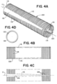
- FIG. 4a-d Another example of a support tube framework 110 having twin tapered spines 116 spaced 180 degrees apart is shown in Fig. 4a-d . Similar to Fig. 3 , the spines can be tapered at various different angles along their length, or the taper can be a curve relative to the longitudinal axis 111 to transition the stiffness of the support tube 100 along its length. In general, the support tube 100 can be stiffer at the proximal end 112 and very flexible near the distal end 114 to ensure accessibility as near as possible to the target site of an occlusion.
- the use of additional spines 116 can give the framework 110 greater resistance to localized elongation between the ribs 118 when the support tube 100 is subjected to lateral and tensile loads.
- the disposition of the spines 116 of the tube diametrically opposed to each other can encourage bending of the framework 110 in a single plane 120 extending through the two spines (see Fig. 4a ).
- This configuration coupled with the opposing sets of junction points 126 for the ribs 118, can aid in delivering a balanced and consistent push or thrust force through the length of the catheter.
- Multiple spines also help the support framework resist longitudinal compression during deployment to ensure exact placement at a treatment site.
- the opposing spine arrangement can also prevent the framework 110 from bending either spine in a direction circumferentially normal to the spine, a direction more prone to kinks or potentially fracture in locations where the width of the spine strut can exceed its thickness.
- a support tube 100 in which the ribs 118 of the support framework 110 are arranged in a coiled helical configuration about the longitudinal axis 111 of the support tube 100.
- the coiled structure can be produced with an overlapping spine 116 as shown in Fig. 5a , or the structure can be formed integrally by laser cutting a single hypotube with ribs and spines.
- two spines 116 can be formed 180 degrees apart along the length of the coil, as in Fig. 5b .
- a helical configuration for the ribs 118 with two spines can mean the respective junction points 126 of a rib with the spines are axially offset on opposing sides of the support framework 110.
- the pitch between ribs 118 can be varied to further optimize the stiffness profile of the support tube 100. Reducing the rib pitch and increasing the thickness of rib struts can each contribute towards adding stiffness to a given region of the tube, whereas increasing rib pitch and/or decreasing rib width can reduce the stiffness properties of a given section. For example, a more proximal rib thickness 141 can be greater than the thickness 142 of a more distal rib, or a proximal rib pitch 139 can be less than a distal rib pitch 140, to add additional flexibility to the distal portion of the catheter. Similarly, a more proximal spine width 138 can be greater than a more distal spine width 136 to yield the same effect.
- the combination of the aforementioned support framework 110 parameters of the ribs 118 and spines 118 with variations in the outer jacket or membrane material hardness and/or thickness can be optimized to provide a catheter body with effective pushability, trackability, and torquability in various regions of the support tube 100 such that the catheter can be delivered along the most challenging vessel paths to reach remote target treatment locations.
- a support tube 200 can have a framework 110 with interrupted double spines 214 where adjacent linear segments of the spines are positioned 90 degrees apart and run parallel to the longitudinal axis 111 of the tube.
- This configuration can be formed by cutting a series of rounded radial slots 212 into alternating and opposing sides of a hypotube or other tube stock to form adjacent ribs 118 along the length of support tube 200.
- This design effectively has interrupted spines at 90, 180, 270, and 360-degree locations around the framework 110 which will allow the tube to bend in two perpendicular bending planes 120, 121 which are aligned axially to extend through each of the interrupted spines 214.
- interrupted spines which define multiple bending planes can allow for a greater freedom of movement in three-dimensional vessel paths.
- such a design can have a reduced column stiffness and be prone to elongate axially under tension, such as when an expandable mouth of the catheter is retracted into an outer intermediate catheter. Expansion of the support tube can inhibit the mouth from collapsing down and exerting a better grip on a captured clot.
- one or more separate and continuous wire spines can be incorporated integrally with or separate to the support tube 200.
- the outer polymer jacket or membrane can be used to fuse the hypotube support framework 110 and wire spines together.
- the wire spines can add integrity to the structure under tensile loading and prevent the tube from axially elongating when retracting a catheter tip 42 with an expanded mouth into an outer sheath of intermediate catheter.
- the width of the rib 118 struts can be increased to adjust the stiffness in a way which can prevent undesired elongation of the support tube 200.
- a support tube 100 can have a framework 110 with looped ribs 118 joined by a helical spine 117 extending between the proximal end 112 and the distal end 114 of the framework.
- a similar design is illustrated in Figs. 8a-d , where two helical spines 117 extend out-of-phase with each other 180 degrees apart. Helical spines allow the support tube 100 to twist about the longitudinal axis 111 along the length of the tube.
- helical spines may also tend to straighten and elongate when support tube 100 is subjected to tension.
- the pitch of the helix can be increased to where the twist is very gentle and, locally, the spine or spines are nearly straight.
- a pitch between 10 mm and 200 mm can be used, more preferably between 50 mm and 100 mm.
- a compound design can have a support framework 110 where a helical spine or spines 117 merge with sections of the framework where the spine or spines are straight relative to the axis 111. Regions of the support tube 100 with more flexible outer covers or jackets (not shown) can be aligned with the straight spines to reduce the likelihood of tensile elongation.
- cutouts 128 can be made with large edge radii as shown in Fig. 8e .
- the cutouts 128 can locally relieve strain at the junction points 126 as the support framework 110 twists about the longitudinal axis 111.
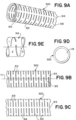
- the support tube 300 can have substantially tubular section, such as a hypotube or polymeric extrusion, with a pattern of cuts forming radial slots 312 spaced around a longitudinal axis 111.
- the interruptions can be sequenced so the discontinuities in the cuts align axially to form one or more continuous spines 314.
- the radial slots 312 form two continuous axial spines 314 spaced 180 degrees apart to maintain a smooth stiffness profile on alternate sides of the support tube 300.
- the cuts forming the radial slots 312 can be completely circumferential around the support tube 300. Sections around the circumference of the tube can incorporate geometric features which form a keyed interface to interlock with adjacent axial sections such that longitudinal and torsional loads can be transmitted without the use of spines.
- the keyed interface can be a dovetail or similar arrangement, so the support tube body fits together like a puzzle.
- the keyed joints can be maintained but the radial slots 312 can be cut with discontinuities to form continuous or discontinuous spines for circumstances where additional pushability is desired.
- the radial slots 312 can be in a helical configuration and include interruptions in an alternating pattern such that they form an interrupted spine or spines 315 which are angularly offset from the one or more continuous spines 314, as seen in Fig. 9b and Fig. 9c .
- the helix cut pattern can include one or more radial cuts per rotation 316 about the longitudinal axis 111.
- three cuts per revolution are utilized.
- Each of the cuts or radial slots 312 can be cut at a constant length, or variable lengths can be used so that lateral flexibility of the support tube 300 can be provided in multiple planes.
- FIG. 10a-b Another support tube 300 with a hypotube or polymeric extrusion having radial slots 312 cut into the tubular section is shown in Fig. 10a-b .
- the cuts can be planar with the transverse axis on alternating sides of the support tube 300.
- the radial slot 312 cuts can terminate or transition to a transverse cut, forming an "I"-shaped or "T"-shaped pattern defining one or more continuous axial spines 314.
- the transverse cuts of the pattern can serve as a strain relief cutout 128 feature, which can vary in thickness and increase the free length of the spine or spines so that the support tube 300 can flex more easily about the bending planes.
- the I-slots 316 and T-slots 317 can alternate in an offset pattern on either side of to form two continuous spines spaced 180 degrees apart, as pictured in Fig. 10b .
- Two continuous spines can allow the support tube 300 to maintain significant longitudinal stiffness along the axis 111.
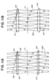
- FIG. 11a and Fig. 11b Flat patterns showing variations of support tube 300 with T-slots 317 and strain relief cutouts 128 are illustrated in Fig. 11a and Fig. 11b .
- the T-slots 317 can be cut at an angle, or with curves as shown in the figures, such that the formed members are contoured ribs 320 which vary in thickness about the longitudinal axis 111 of the tube.
- the contoured ribs 320 can be a wider width near the opposing continuous spines 314 and narrow to a thinner width in mid-span between the spines, as seen in Fig. 11a . This arrangement offers a greater space for the ribs 320 to move in bending while offering additional support for the tube 300 against the vacuum pressure under aspiration.
- the strain relief cutouts 128 of the ribs 320 can be T-slots 317 with a gentle curve or radius at the spines 314 like those of Fig. 11b . While offering additional space for the contoured ribs 320 to bend proximally or distally relative to each other in tortuous vessels, curved T-slots can give additional flexibility to the support tube 300 by promoting bending in directions tangential to the curve.
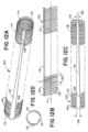
- Fig. 12a-d illustrate another example of a support tube 100 which can have a framework 110 machined from a tube where a single axial spine 116 anchors a plurality of ribs 118 extending between a proximal end 112 and a distal end 114.
- the spine can have at least a distal first width or thickness 136 which is less than a proximal second width of thickness 138 to provide good pushability to the framework 110 proximally and a more flexible spine distally to contort and twist through vessel paths.
- the ribs 118 can be cut an angle 130 so that the free ends extend distally to the junction points 126 of the ribs with the spine 116. Although angled, the ribs 118 can maintain a circular inner lumen 119 (as seen in Fig. 12d ) and outer diameter. This arrangement allows the ribs 118 to move proximally relative to the spine 116 when compressed between the junction points 126 and a firm clot that resists being stretched into the nominal resting inner diameter of the framework 110. This compressive force transmitted to the most distal rib can be transmitted proximally to adjacent ribs by the outer cover and/or jackets (not shown) disposed around or encapsulating the framework.
- the jacket can be reflowed to the cut support framework 110 so that it sits between and transmits longitudinal loads between adjacent ribs 118.
- the jacket can also be polymeric so that it has the elasticity to stretch and expand in diameter in response to movement of the ribs. Compressive forces from a clot can cause the cross-sectional area of the lumen 119 to increase as the ribs move proximally to a position where the rib angle 130 is more perpendicular to the spine 116 and longitudinal axis 111 and the elastic jacket expands radially outward, temporarily increasing the reception space available for clot capture.
- a variable-width spine 116 can link variable-stiffness sections of the support tube, where a proximal rib pitch 139 of the ribs 118 in a more proximal axial section is greater than a distal rib pitch 140 in a more distal axial section.
- the spine 116 can have a first spine width 136 near the distal end 114 of the support framework 110 less than a second spine width 138 near the proximal end 112, thereby increasing the distance between respective junction points 126 between the spine and the ribs 118.
- the spine can taper to other intermediate widths between the first and second widths.
- the ribs themselves can also be cut at various thicknesses within different axial sections of the support framework 110 as desired or can be formed with different thicknesses at various clocking positions around the longitudinal axis 111.
- a support tube 100 similar to the example of Fig. 13a is shown connected at the distal end 114 to a self-expanding catheter tip 42 framework in Fig. 14 .
- the struts of this framework can be formed from Nitinol or another shape-memory material with sufficient elastic strain capacity such that the elastic limit would not be exceeded when the tip is constrained and delivered in the collapsed configuration within an outer catheter. Additional frameworks of wire or non-superelastic materials can also be envisaged, where a lower degree of strain is required to move from a collapsed state for delivery to an expanded state for clot retrieval.
- the spine 116 of the support framework 110 can transition directly into a spine extension 44 strut or struts at the distal end 114, and the spine can be integral with the extension (e.g., cut from the same hypotube) such that the stiffness profile of the catheter is smoother and weak transitions can be eliminated.
- Supporting arms 45 of the expansile tip 42 can extend distally from central junctions with the spine extension 44, or one of more of the arms can be connected with the distalmost rib of the support framework 110.
- the arms can be connected with other struts or themselves can include radial curves to form the circumference of the enlarged distal mouth 46 of the catheter tip 42.
- the support arms 45 can be arranged so that they expand radially outward as a clot is being aspirated or, for example, when a thrombectomy device is being retracted through the mouth 46 for a higher success rate when targeting stiff clots.
- the support ribs 118 of the support tube 100 can be formed at an angle relative to the axis of the tube so the ribs are substantially cylindrical in profile but do not have a planar cross-section.
- the free ends of the ribs 118 can move proximally relative to the longitudinal spine 116 when under compressive loads, such as during clot retraction. Proximal movement of the ribs 118 can have the effect of expanding the inner diameter of the catheter lumen 119 locally as the clot is retracted through the support tube.
- An elastomeric outer jacket or membrane covering the support framework 110 and expansile tip 42 can be configured to allow the support arms 45 and ribs 118 to expand under these compressive loads.
- FIG. 15a-d An example of a support tube 100 having a tubular support framework 110 where axially curved ribs 118 are spread between two continuous spines 116 spaced 180 degrees apart is shown in Fig. 15a-d .
- the ribs 118 can have proximal peaks 136 defining a most proximal point where the ribs intersect the spines 116 at the junction points 126.
- the profile of the ribs 118 beyond the junction points 126 can take on a gently undulating non-planar cross-section which can have one or more curves, but still defines a substantially cylindrical catheter lumen 119. As seen isometrically in Fig.
- the rib profile can have a first proximal curve 132 radially offset from the proximal peak 136 and a second distal curve 134 radially offset from the proximal curve and culminating in distal peak 138, so that at least a portion of the ribs is distal to the connection at the junction points 126. It can also be appreciated that the corresponding junction points 126 with each spine 116 can also be axially offset proximally or distally to the opposed junction point with the other spine.
- Ribs 118 that form a substantially cylindrical profile but do not have planar cross-sections have the ability to expand in compression during retraction of a clot from a blood vessel to the inner lumen 119 of the catheter, thereby allowing this configuration of the support framework 110 to "swallow" dense clots that may otherwise be restricted from entering a non-expandable form.
- the support framework 110 with ribs 118 having one or more axial curves can be arranged with the spines 116 connected in-line at the distal end 114 with the support arms 45 of an expanding catheter tip 42 framework, as illustrated in Fig. 16 .
- Connecting the arms 45 in-line with the spines 116 allows for the advancement forces to be transmitted directly along the spines to the support arms for enhanced pushability when the catheter is being advanced through an outer intermediate catheter.
- This configuration also allows the distal peaks 138 of the ribs to be kept free so that frictional and compressive forces generated between the support framework 110 and an outer catheter during advancement, due to the expansile tip pressing radially outwardly against the outer catheter, are not transmitted in a direction which would cause the ribs to expand.
- This expansion can otherwise negatively affect deliverability by having at least a portion of the support tube 100 pressing against the inner surfaces of the outer catheter, generating increased friction.
- a support tube 100 having a support framework 110 similar to that of Fig. 15a-c but with ribs 118 extending in a wave pattern circumferentially can be seen in Fig. 17a-d .
- the ribs 118 can intersect with two offset spines 116 spaced 180 degrees apart in a substantially perpendicular fashion at the junction points 126.
- the proximal curve 132 and distal curve 134 of each rib can therefore form a proximal peak 136 that is circumferentially offset from each spine 116.
- the distal peak 138 of the ribs can be kept free to allow the ribs to flex individually.
- the wave pattern generates more contact points between the ribs 118 and an outer jacket or membrane to distribute forces more evenly across the circumference while still maintaining the ability to expand in compression. It can also be appreciated that the strut width of the ribs and spines can be varied, and the corresponding junction points axially offset at each spine to further tune the movement of the ribs 118 and the stiffness profile of the support framework 110.
- Fig. 18a-d shows a case where the ribs 118 of the support framework 110 can have proximal curves 132 and distal curves 134 bending in opposing directions to those of the ribs in Fig. 17a-d .
- Undulations in the ribs of the support tube can allow the tube to expand so that stiff clots that cannot be compressed into the nominal resting internal diameter of the device can instead be retrieved by the radial expansion of the support framework 110 which can occur when aspiration is maintained on an otherwise lodged or incompressible clot.
- the outer jacket or membrane covering the support framework 110 can be made of an elastomeric material so that the support tube is not restricted from expanding.
- twin spines 116 in the examples where the ribs have a circumferential undulations or wave patterns can provide better pushability than a single spine while preventing the support tube 100 from elongating under tension when an expandable tip 42 is being drawn proximally into an outer intermediate catheter.
- Cutouts 128 increase the movement capability of individual ribs with respect to the spine or spines 116 while providing strain relief at the interface.
- a highly flexible catheter can reduce the risk of cracking or ultimate fracture by reducing the geometric stress concentration at the junctions through strain relief cutouts 128. Cutouts 128 at the junction points 126 also encourage the ribs to flex independently to better accommodate the loads of a procedure.
- Fig. 19a-c Various additional geometries of strain relief cutout patterns can be seen in Fig. 19a-c . These features can be introduced in a support tube 100 that is a hypotube by incorporated an additional machining step to the rib cuts or can be cut or formed integrally when the support tube is extruded or injection molded. Depending on flexibility preferences in a particular axial segment of the tube support framework 110, a user can introduce beveled or rounded strain relief cutouts 128 to the corners of the junction points 126, as in Fig. 19a . Such a cutout can be particularly useful in situations where the rib space is very dense and there is insufficient room for other stress reducing geometries.
- a cutout 128 at the junction points 126 with an enlarged, more generous radius can be used to reduce stresses further, as illustrated in Fig. 19b .
- fine rib spacing can be retained by adding smaller relief cutouts 128 to the corners of the junction points 126, as in Fig. 19c .
- FIG. 20a-c illustrates several examples where a support tube 100 has a support framework 110 in which a series of supporting ribs 118 merge into a single spine connector 146 for connections with one or more spines 116.
- Each set of support ribs may comprise one, two, three, or more ribs 118.
- a pair of ribs 118 have opposing wing segments 147 which curve or taper centrally into a spine connector 146 joining to spine 146.
- support ribs 118 in sets that have a single connection to the one or more spines 116 a longer length of spine is free to bend for a given density of ribs.
- a similar concept with three ribs 118 joining into a single connection is shown in Fig. 20b .
- the outer ribs of the set can have wing segments 147 to merge with the central rib, which can have a direct connection with the spine connector 146.
- a series of supporting ribs 118 can merge into opposing spine connectors 146 for connections with twin spines 116 spaced 180 degrees apart as shown in Fig. 20c . Additional spine can also be envisioned. Opposing twin spines can provide better pushability than a single spine while preventing the support tube 100 from elongating under tension, such as when an expandable tip 42 is being drawn proximally into an outer catheter. Fewer connections with the spines can give the framework 110 better flexibility to bend along the bend plane passing through the longitudinal axis 111 and each of the spines 116.
- FIG. 21a A further example of a support tube 400 having a different configuration where radial slots create a puzzle-cut pattern is illustrated in Fig. 21a .
- the puzzle cut tube can be substantially a series of interlocking ribs or rings 403. As each ring 403 is not integral with adjacent rings either proximally or distally, the puzzle cut tube can twist about the longitudinal axis 111, A puzzle cut support tube 500 construction can also resist tensile elongation due to engagement of adjacent interlocking features 404, 405. Distal interlocking features 405 can engage a particular ring with the next distal ring, while proximal interlocking features 404 can engage with the next proximal ring.
- Flexibility of the puzzle cut support tube 400 can be varied by increasing or decreasing the size of the ligament 406 between the interlocking features of the rings 403.
- Fig. 21b illustrates how the flexibility can also be varied by altering the number, shape and/or spacing of the interlocking features 404, 405.
- the longitudinal spacing 408 and circumferential spacing 410 between adjacent rings 403 can be controlled through the thickness of the cuts or through machining operations.
- the support tube can thus lengthen by the sum of the spacings 408 distributed longitudinally.
- allowable twist can be adjusted by altering the circumferential spacing 410.
- the twist properties offered by a puzzle cut design for the support tube will aid in the catheter bending and torqueing in multiple planes as it is advanced through tortuous vascular paths.
- Fig. 21c and Fig. 21d show how a support tube 400 can have a puzzle cut design with interlocking features while incorporating a longitudinal spine 416.
- a spine 416 can be added by aligning interruptions in the puzzle cut radial slots such that the rings 403 are fixed longitudinally at the spine, as seen in Fig. 21d .
- segments of the spine 416 can also be circumferentially offset, or the thickness of the spine can be different at various axial positions along the length of the support tube 400.
- the addition of a longitudinal spine 416 will help prevent the puzzle cut tube from lengthening under tensile loads. Additionally, a single spine will have minimal impact on the ability of the puzzle rings 403 to twist, so the catheter support tube can maintain its trackability advantages.
- a puzzle cut support tube 400 can incorporate two longitudinal spines 416 spaced 180 degrees apart.
- the addition of two spines 416 will prevent the support tube from lengthening under tensile loading and impart a preferred bending plane on the tube. If aligned parallel to the longitudinal axis 111 as shown, twin spines spaced 180 degrees apart will have minimal impact on the ability of the puzzle rings to twist, and the twist will change the preferred bending place of the tube to a degree controlled by the designed twist so that the support tube is capable of self-adjusting as it is advanced through tortuous vessels.
- a support tube 500 can have a metal and/or polymer strand or wire construction formed into a braided or coiled structure 510, as shown in Fig. 22a .
- the strands 511 of the braided pattern 510 can form a radial array as a continuous structure in order to approximate a singular body support piece and be of sufficient density to support an outer membrane, similar to that of a laser-cut hypotube.
- the strands 511 of the support tube 500 can be formed on a straight mandrel so that a portion or portions of the tube flare radially outward to form a seal with the inner diameter of an outer or intermediate catheter.
- Braided structures are known in the art to offer good flexibility in order to optimize the performance of catheter tubing.
- braids can tend to lengthen and reduce in cross-section diameter, while under compression, braids can expand in diameter and shorten.
- one or more interwoven spines 516 can be incorporated with the braid.
- the spine 516 will prevent the braided pattern 510 from elongating in tension or shortening in compression.
- one or more spines 516 may be overlaid on top of the braided pattern 510 for simpler manufacturer.
- the spine 516 can be tacked in place with adhesives or other suitable method.
- This expansion can be achieved by changing the size, orientation, or other properties of the strands 511 of the pattern 510. Further flexibility can be gained by altering the braid angle 512 or picks per inch (PPI) of the pattern.
- the braid angle 512 of the strands 511 and the density of the pattern can be chosen for the preferred axial and transverse mechanical properties of a given section of the support tube 500. For example, the braid angle and/or PPI can be different in a more proximal portion of the support tube, giving the proximal portion better pushability and torque response than a more flexible distal portion.
- the braid angle 512 can be less than 90 degrees and over 20 degrees so that there is freedom for the support tube 500 to longitudinally compress. Maintaining the braid angle closer to 90 degrees will give the framework more flexibility than braid angles closer to 20 degrees, as the wires or strands of the 20-degree braid will be dispositioned in a more longitudinal direction. A braid angle 512 of greater that 90 degrees can also expand but to a lesser degree due to the denser spacing between braid strands 511.
- the braid pattern 510 can have an elastomeric outer cover or jacket (not shown).
- the jacket can be reflowed to the outer surface of the braided tube or made to encapsulate the strands 511. Reflowed jacket materials will fill the voids between the braided pattern 510 and spine 516 further dampening the expansion or contraction of the tube. Encapsulating the pattern 510 with a reflowed polymer jacket can also help hold the braid and spine(s) 516 together.
- the jacket can be impermeable, or alternatively the braided or coiled pattern 510 can be of sufficient density so that fluid flow is substantially impeded between the exterior and interior of the support tube, such that an impermeable cover or seal is not necessary.
- any of the herein disclosed support tubes for clot retrieval catheter designs can be used in conjunction with a mechanical thrombectomy device.
- the combination of mechanical thrombectomy with aspiration through a funnel-like tip section can increase the likelihood of first pass success in removing a clot.
- a funnel-like shape of the tip section can reduce clot shearing upon entry to the catheter, arrest flow to protect distal vessels from new territory embolization, and also direct the aspiration vacuum to the clot face while the mechanical thrombectomy device will hold a composite clot (comprised of friable regions and fibrin rich regions) together preventing embolization and aid in dislodging the clot from the vessel wall.
- the shape of the tip can also aid in preventing fragmentation if the clot enters the mouth of the catheter at an offset position.
- the mechanical thrombectomy device will support the lumen of the vessel during aspiration such that it will be less likely to collapse under negative pressure and hold the clot together should the clot comprise an array of stiff and soft portions that may otherwise fragment.
- the mechanical thrombectomy device can also allow the user to pinch a clot that will not fully enter the lumen of the clot retrieval catheter, thereby ensuring that the clot will not dislodge from the clot retrieval catheter as the clot retrieval catheter, clot, and mechanical thrombectomy device are retracted as one through the vasculature, through the outer catheter, and outside of the patient.
- the interaction between the outer catheter and the expanded mouth will aid in gradually compressing the clot so that it can be pulled through the outer catheter with the clot retrieval catheter and mechanical thrombectomy device. If the clot is still too large to enter the outer catheter, the clot retrieval catheter and mechanical thrombectomy device can be retracted proximally through the vessel and into a second larger outer catheter such as a balloon guide. Should the clot still be too stiff to retrieve through the second outer catheter, all devices can be retracted together as one through the vasculature and outside of the body.
- the clot retrieval catheter may be designed to work with an outer catheter such as a 7Fr, 8Fr, 9Fr or 10Fr long guide sheath or balloon guide sheath. Alternatively, the clot retrieval catheter may be designed to work with an outer catheter such as a 4Fr, 5Fr, or 6Fr intermediate catheter.
- Fig. 23 and Fig. 24 are flow diagrams each comprising method steps for producing a clot retrieval catheter having a support tube according to aspects of this disclosure.
- the method steps can be applied to any of the example systems, devices, and/or apparatus described herein or by a means that would be known to one of ordinary skill in the art.
- step 2310 describes the task of positioning a plurality of ribs along a length, the ribs being oriented circumferentially around a longitudinal axis to define a substantially tubular shaped support.
- the ribs can be circular, helical, or any other suitable shape appropriate for intravascular procedures.
- the ribs can be formed by laser cutting a hypotube, carving radial slots into an extruded tube, or other methods commonly known in the art.
- Step 2320 involves forming or positioning the plurality of ribs such that the flexibility of tubular support varies along at least part of the longitudinal length of the tubular support.
- variable flexibility of the tubular support can be obtained by tuning various properties of the ribs, such as the spacing of the ribs, different thicknesses for the struts of the ribs, and adjusting the planar cross-sectional shape of the ribs.
- the plurality of ribs can be cut or formed at one or more angles which are not perpendicular to the longitudinal axis of the tubular support.
- the angled orientation of the ribs can change the cross-sectional size of the internal catheter lumen, facilitating clot retrieval and/or aspiration.
- Step 2340 can involve forming one or more spines running along the length of the tubular support and can include affixing each rib of the plurality of ribs to the one or more spines.
- the spines can be mechanically connected to the ribs, or the spines and ribs can be formed integrally through the machining of a hypotube or the cutting of radial slots in an extruded tube. Having fixed junction or attachment points to the spine or spines allows the ribs to be configured to move proximally or distally with respect to the spine or spines when the tubular support is subjected to different forces during a procedure, as in step 2350.
- This movement can allow the tubular support to increase in diameter locally as a clot is being withdrawn, or reduce frictional forces generated with the clot retrieval catheter is advanced or retracted through an outer catheter.
- Different configurations of the ribs and spines of the tubular support can be appreciated to encourage movement of the ribs, such as narrowed ribs struts or when a single axial spine is used to give each rib an unconstrained free end.
- the one or more spines of the tubular support are oriented to share the longitudinal axis of the support tube.
- straight axial spines can share an axis parallel to, or a helical spine arrangement can have twists concentric with, the longitudinal axis of the tubular support.
- the spines can also be cut or formed such that the flexibility of the tubular support varies along the length of the tubular support. A thicker proximal width of a spine can transition to a thinner width to maintain good trackability characteristics within vessels while giving distal portions of the tubular support greater flexibility for access.
- a further step for preparing a tubular support for a clot retrieval catheter is shown in step 2430, which can involve fixedly attaching or integrally forming a radially-expanding tip with the distal end of the tubular support so that the catheter can have a large, distal facing mouth which can seal with the vessel and provide local flow restriction/arrest when deployed.
- at least a portion of the tubular support and expandable tip can be covered with a polymeric cover.
- a cover for example, can be a series of outer jackets which are reflowed, injection molding, or laminated to the outer and/or inner radially surfaces of the ribs.
- a coating step can give the surfaces of the tubular support and/or cover lubricious, low- friction properties.
- distal and proximal are used throughout the preceding description and are meant to refer to a positions and directions relative to a treating physician. As such, “distal” or distally” refer to a position distant to or a direction away from the physician. Similarly, “proximal” or “proximally” refer to a position near to or a direction towards the physician. Furthermore, the singular forms “a,” “an,” and “the” include plural referents unless the context clearly dictates otherwise.
- the terms “about” or “approximately” for any numerical values or ranges indicate a suitable dimensional tolerance that allows the part or collection of components to function for its intended purpose as described herein. More specifically, “about” or “approximately” may refer to the range of values ⁇ 20% of the recited value, e.g. "about 90%” may refer to the range of values from 71% to 99%.
Landscapes
- Health & Medical Sciences (AREA)
- Life Sciences & Earth Sciences (AREA)
- Surgery (AREA)
- Veterinary Medicine (AREA)
- Public Health (AREA)
- General Health & Medical Sciences (AREA)
- Engineering & Computer Science (AREA)
- Biomedical Technology (AREA)
- Heart & Thoracic Surgery (AREA)
- Animal Behavior & Ethology (AREA)
- Molecular Biology (AREA)
- Medical Informatics (AREA)
- Nuclear Medicine, Radiotherapy & Molecular Imaging (AREA)
- Biophysics (AREA)
- Pulmonology (AREA)
- Anesthesiology (AREA)
- Hematology (AREA)
- Vascular Medicine (AREA)
- Orthopedic Medicine & Surgery (AREA)
- Media Introduction/Drainage Providing Device (AREA)
- Surgical Instruments (AREA)
- Materials For Medical Uses (AREA)
Abstract
Description
- The present disclosure generally relates to devices and methods for removing acute blockages from blood vessels during intravascular medical treatments. More specifically, the present disclosure relates to a retrieval aspiration catheter.
- Aspiration and clot retrieval catheters and devices are used in mechanical thrombectomy for endovascular intervention, often in cases where patients are suffering from conditions such as acute ischemic stroke (AIS), myocardial infarction (MI), and pulmonary embolism (PE). Accessing the neurovascular bed in particular is challenging with conventional technology, as the target vessels are small in diameter, remote relative to the site of insertion, and are highly tortuous.
- In delivering effective devices to the small and highly branched cerebral artery system, conventional catheters must try and balance a number of factors. The catheter must be sufficiently flexible to navigate the vasculature and endure high flexure strains, while also having the axial stiffness to offer smooth and consistent advancement along the route. Newer designs have been introduced which utilize various methods to alter the stiffness between the proximal and distal portions of the catheter. But abrupt stiffness or geometric changes can hinder trackability, introduce significant stress concentrations, and potentially increase the likelihood of device kinking or buckling.
- When aspirating with traditional catheters, such as a fixed-mouth catheter or a catheter which does not seal with an outer catheter, a significant portion of the aspiration flow ends up coming from vessel fluid proximal to the tip of the catheter, where there is no clot. This significantly reduces aspiration efficiency, lowering the success rate of clot removal. Furthermore firm, fibrin-rich clots can often be difficult to extract as they can become lodged in the tip of traditional fixed-mouth catheters. This lodging can cause softer portions to shear away from the firmer regions of the clot.
- Other designs for aspirating catheters feature a large distal facing mouth to achieve maximum efficiency. For example, the mouth can be designed with a diameter that is considerably larger than the typical delivery catheter or sheath. As a result, the mouth is required to have both a flexible low-profile for delivery within an outer catheter but must deploy and expand to an enlarged configuration at the target site. The supporting tube of the catheter must be sufficiently flexible itself for access while having features capable of transmitting thrust loads effectively to the mouth at the distal tip.
- However, many highly flexible body designs have a reduced diameter incapable of generating the required suction force, while designs with expandable members or separate suction extensions can lack the flexibility to navigate the neurovascular intact. Catheter elements must survive the severe mechanical strains imparted but also generate a sufficient radial force when expanded to prevent collapse of the catheter and the vessel under the suction of aspiration.
- The present designs are aimed at providing an improved retrieval catheter with an expansile tip which incorporates these features to address the above-stated deficiencies.
- The designs herein can be for a clot retrieval catheter which can have a body support tube section which can be tailored to have sufficient flexibly so as to be capable of navigating highly tortuous areas of the anatomy, such as the neurovascular, to reach occlusive clots. The support tube can also be formed with or attached to an expandable catheter tip capable of providing local flow restriction/arrest within the target vessel with a large, clot-facing mouth. The catheter can also be compatible with relatively low-profile access sheaths and catheters for further deliverability advantages.
- The clot retrieval catheter can have a substantially tubular body with a support framework defining a longitudinal axis. A large catheter lumen can be configured for the passage of guidewires, microcatheters, stent retrievers, and other such devices. The lumen can also direct aspiration to the catheter tip. The tubular body can extend from a proximal end and terminate at a distal end, at which an expandable tip can be integrally formed or fixedly connected. The tip can be configured to expand from a collapsed delivery configuration to an expanded deployed configuration when deployed at the site of an occlusive thrombus.
- The support framework can have one or more axial spines extending longitudinally from the proximal end to the distal end. A series of loop ribs can be disposed along at least a length of the longitudinal spine or spines. The ribs of the support framework can define the internal lumen of the catheter extending therethrough. Each rib can intersect with the one or more spines at junction points. The junction points can have strain relief cutout features or similar geometry to relieve stress at the rib-spine junctions when the catheter is tracked through tortuous vessels in the vasculature. In some cases, rather than having independent junction points, multiple ribs may unite into a spine connector to improve the flexibility of the support tube by minimizing connections to the spine. Ribs can have wing segments with curves or taper so they merge into a spine connector which has a single junction point with each rib.
- The ribs and spines can be monolithically formed though laser machining of a hypotube or extrusion of a polymeric tube. In another example the tubular body can be of metallic braid or coiled wire construction. The spine can be fixedly connected to, or formed integrally with, a part of the expansile tip.
- At least a portion of the tubular section can form a seal or flow restriction with an outer catheter such that aspiration is directed to the distal tip of the clot retrieval catheter. A polymeric cover or membrane can be disposed around at least part of support framework and tip to enclose the catheter body. In another example, the cover can be a series of polymeric jackets having variable stiffness and flexure properties. The cover can be reflowed, adhered, and/or stitched to the framework of the support structure. The cover can further be coated with a low-friction layer or film to improve trackability and mitigate the risk of binding or excessive friction when delivered through an outer catheter.
- The trackability and flexibility of the catheter in the vasculature can be tailored by adjusting properties of the support tube. For example, bending planes for the support tube can be defined through the location of the axial spines where the spine or spines are straight, parallel members. In another example, the spine or spines can be disposed in a spiral or helical pattern around the longitudinal axis of the support tube. The spine or spines can have a width in more proximal sections of the support tube that is different from the spine width in more distal sections. A transition from a one spine width to another can be a continuous taper or can transition between successively more flexible axial segments of the framework.
- The struts forming the ribs of the framework of the support tube can have various widths, such that a first rib width of one rib is different than a second rib width of another rib. The ribs can also be a helical pattern, where the coiled structure can stagger the junction points between the ribs and the spines. The spacing, or pitch, of adjacent ribs can also be varied between the proximal end and the distal end of the support framework, such that one segment of the framework can have a dense rib pattern with greater stiffness than another segment with larger rib spacing.
- In another example, the ribs can be cut or formed so they are disposed at an angle not perpendicular to the longitudinal axis of the support framework, such that the diameter of the internal lumen can change as the ribs move in response to tensile or compressive forces on the support tube during a thrombectomy procedure. The ribs can also be formed so they have a non-planar cross section and the profile of the rib struts has one or more proximal and/or distal curves or undulations. The ribs can also be configured to move relative to their respective junction points with the spine or spines so the support tube can locally expand for the passage of a captured clot that is firm or incompressible.
- In another example, a support tube for forming the body of a catheter assembly can have a tubular support framework having a proximal end, a distal end, an internal lumen, and a pattern of radial slots configured around a longitudinal axis. The radial slots can be, for example, cut into the circumference of an extruded polymeric tube through various clocking positions so that they are discontinuous and not completely circumferential. The cuts can form slots that are a constant length of variable length. By aligning segments of the cuts, the slots in the support tube can define interrupted, continues, or both interrupted and continuous spines running the length of the tube.
- In one instance, adjacent interrupted radial slots offset from each other by 90 degrees can form two interrupted spines. When offset in this fashion, the two interrupted spines can define two bending planes normal to each other and perpendicularly aligned through the longitudinal axis of the support framework. Additional spines and bending planes can be formed interrupting the cuts in additional places around the circumference of the tube and axially aligning or offsetting adjacent cuts as desired.
- In another case, the radial slots can be cut in a helix pattern where the cuts of adjacent revolution twists are aligned to form one or more continuous and/or discontinuous spines. In one example, the helix pattern of interrupted slots can include at least two cuts per rotation. In another example, the helix pattern can include more than two cuts per rotation to form both continuous and discontinuous spines circumferentially offset from one another. Multiple cuts per rotation can allow flexibility along multiple different planes.
- The radial slots of the support tube can be almost or completely circumferential around the longitudinal axis. With this configuration the slots divide the axial length of the support tube into a series of rings between the proximal end and the distal end of the tube. The rings can be a constant length or can vary in length. Individual rings can be joined to adjacent rings through a series of interlocking features around the circumference of each ring. Distal interlocking features can engage a particular ring with the next distal ring, while proximal interlocking features can engage with the next proximal ring. Overall flexibility of the tube can be varied by altering the number of interlocking features or changing their shape or circumferential spacing. Interlocking features can allow the support tube to transmit axial and torsional loads and minimize expansion of the tube in tension without the use of spines. Alternatively, one or more spines can be formed in the support tube by having the slots interrupted at points around the circumference and then aligning or offsetting the interruptions to create continuous or discontinuous spines.
- In another example, a support tube for the body of a catheter can have a substantially cylindrical braided pattern formed by a plurality of strands about a longitudinal axis. The cylindrical braid of strands can define the lumen of the support tube. One or more spines can extend longitudinally along the braided pattern between its proximal end and distal end; and a polymeric cover can be disposed around at least a portion the braided pattern. The polymeric cover can encapsulate at least a portion of the braided pattern so as to fill in the gaps in the braid.
- At least one of the one or more spines can interweave with the strands of the braided pattern. A design with spines woven into the braid can inhibit the structure from elongating in tension or shortening in compression. The spines can have variable width between the proximal end and the distal end of the braided pattern for improved bending flexibility.
- In a braided pattern, an angle is formed where two strands come together in the weave. The angle formed by the strands can be used to tailor mechanical properties, and different angles can be used for different axial segments of the support tube. In one case, the angle of the braid pattern is in the range of approximately 20-90 degrees.
- Also provided is a method for constructing a clot retrieval catheter. The method can have the step of positioning a plurality of ribs along a length to define a tubular support for the catheter. The ribs can be circular or of some other shape and be oriented around a longitudinal axis of the tubular support. The ribs can also be oriented at an angle not perpendicular to the axis, allowing them to move under the forces of the thrombectomy procedure. When a clot is drawn into the distal mouth of the catheter, compressive forces can be transferred to the ribs to cause at least a portion of the ribs to move proximally relative to the longitudinal axis, effectively increasing the local diameter of the inner lumen of the catheter.
- One or more axial spines can be formed along the length of the tubular support, connecting the plurality of ribs at junction points and allowing thrust to be transmitted though the tubular support. In one example, the spine or spines can be formed integrally with the ribs of the support, such as a laser cut hypotube. The spine or spines can be linear and parallel to the longitudinal axis or can be formed as a spiral or helix about the axis. A radially expandable tip can be connected to, or formed integrally with, the distal end of the tubular support. A further step can involve having a polymeric cover disposed around at least a part of the tubular support and expandable tip. The cover can be elastic so that it stretches as the tip expands, or it can be baggy or loose around the frame so that the whole radial force of the tip can be transmitted to the walls of a vessel.
- Another step can involve forming and positioning the ribs and spines to tailor the bending stiffness of the catheter tubular support at different portions along the length. The ribs can, for example, be spaced more densely at the proximal end, or have a thicker strut width. Similarly, the spine or spines can have an increased width proximally and taper to a narrower profile distally, to provide good pushability and give increased distal flexibility for access.
- Bending stiffness can be tailored either by or a combination of varying the cut width and rib width. Where the cut width is kept constant, for instance, the width of a laser beam, the rib width and/or spine(s) width can be varied to tailor bending stiffness. Where the cut width is varied, the rib width can be kept constant or varied and the laser can be used to remove pieces of material. It is appreciated that by using cut width equal to that of the laser beam, no pieces of material are removed, and the cost of manufacture is greatly reduced. On the other hand, by using the laser to remove pieces of material, greater variation in shaft design can be achieved. It is also appreciated that combination of both approaches may be used such that the shaft incorporates more cost-effective cutting/processing means at the proximal end and more costly approaches are kept to a specific distance at the distal end where more complicated cuts can be required to achieve the desired performance. For example, the distal end may include a length of 20cm with cuts that remove pieces of material and also include the cutting of an expandable tip. In another example, a proximal section of the shaft may be cut from SS and be joined to a distal section cut from NiTi in order to reduce overall cost while affording the benefits of NiTi to the distal end of the device where it is required for enhance resilience to tight bending curves and also to provide expansion and recovery characteristics. For such a device, the SS and NiTi sections can be joined by welding directly, by welding to a more weldable intermediate metal such as platinum. As an alternative, laser cut interlocking features can hold both cut tubes together in a longitudinal direction. An outer membrane cover or jacket can hold the tubes together in a radial direction.
- Other aspects and features of the present disclosure will become apparent to those of ordinary skill in the art, upon reviewing the following detailed description in conjunction with the accompanying figures.
- The above and further aspects of this invention are further discussed with reference to the following description in conjunction with the accompanying drawings. The drawings are not necessarily to scale, emphasis instead being placed upon illustrating the principles of the invention. The figures depict one or more implementations of the inventive devices, by way of example only, not by way of limitation.
-
Fig. 1 is an isometric view of a clot retrieval catheter with a tubular support and an expandable distal tip according to aspects of the present invention; -
Fig. 2 shows an isometric view of a tubular support with circular ribs and two axial spines, according to aspects of the present invention; -
Fig. 3a-d are a series of views of a support tube according to aspects of the present invention; -
Fig. 4a-d are a series of views of another support tube according to aspects of the present invention; -
Fig. 5a shows another support tube with helical ribs according to aspects of the present invention; -
Fig. 5b illustrates another support tube with variable rib pitch according to aspects of the present invention; -
Fig. 6a-d are a series of views of another support tube according to aspects of the present invention; - F
ig. 7a-d are a series of views of another support tube with a helical spine according to aspects of the present invention; -
Fig. 8a-d are a series of views of another support tube with dual helical spines according to aspects of the present invention; -
Fig. 8e is a representation of the strain relief cutouts in a support tube according to aspects of the present invention; -
Fig. 9a-d are a series of views of another support tube with radial slots according to aspects of the present invention; -
Fig. 9e is a representation of the cuts per revolution for the radial slots in a support tube according to aspects of the present invention; -
Fig. 10a-b are two views of another support tube with radial T-slots for strain relief according to aspects of the present invention; -
Fig. 11a is a flat pattern of an example support tube with T-slots and contoured ribs according to aspects of the present invention; -
Fig. 11b is a flat pattern of another example support tube with T-slots and contoured ribs according to aspects of the present invention; -
Fig. 12a -d are a series of views of another support tube according to aspects of the present invention; -
Fig. 13a-d are a series of views of another support tube according to aspects of the present invention; -
Fig. 14 shows an expanded distal tip of the catheter connected to the support tube ofFig. 13a according to aspects of the present invention; -
Fig. 15a-d are a series of views of another support tube according to aspects of the present invention; -
Fig. 16 shows an expanded distal tip of the catheter connected to the support tube ofFig. 15a according to aspects of the present invention; -
Fig. 17a-d are a series of views of another support tube according to aspects of the present invention; -
Fig. 18a-d are a series of views of another support tube according to aspects of the present invention; -
Fig. 19a-c illustrate various possible strain relief cutouts according to aspects of the present invention; -
Fig. 20a shows a support tube with multiple ribs sharing spine connections according to aspects of the present invention; -
Fig. 20b shows an alternate support tube with multiple ribs sharing spine connections according to aspects of the present invention; -
Fig. 20c illustrates another support tube with multiple ribs sharing spine connections to multiple spines according to aspects of the present invention; -
Fig. 21a shows a puzzle cut support tube with rings joined by interlocking features according to aspects of the present invention; -
Fig. 21b shows a closer view of the features of the support tube ofFig. 21a according to aspects of the present invention; -
Fig. 21c illustrates another puzzle cut support tube with rings joined by interlocking features and a single spine according to aspects of the present invention; -
Fig. 21d shows a closer view of the features of the support tube ofFig. 21c according to aspects of the present invention; -
Fig. 21e illustrates another puzzle cut support tube with rings joined by interlocking features and twin spines according to aspects of the present invention; -
Fig. 21f shows a closer view of the features of the support tube ofFig. 21e according to aspects of the present invention; -
Fig. 22a-b are views of a support tube of braided construction according to aspects of the present invention; and -
Fig. 23-24 are flow diagrams outlining a method of use for the system according to aspects of the present invention. - The objective of the disclosed designs is to create a clot retrieval catheter with a radially expandable distal tip for local flow restriction/arrest and a tailored, highly flexible body section capable of navigating the tortuous areas of the vasculature to reach an occlusive clot. Such advantages can be especially beneficial in the case of stroke intervention procedures, where vessels in the neurovascular bed are small and very tortuous, where a carefully designed axial and bending stiffness profile can inhibit kinking and binding. The catheter can also be compatible with relatively low-profile access sheaths and catheters, so that a puncture wound in the patient's groin (in the case of femoral access) can be easily and reliably closed. The support structure can also feature internal and/or external low-friction liners, and an outer polymer jacket or membrane disposed around the support structure.
- An advantage of using an expanding mouth clot retrieval catheter with an outer catheter is that if both have the flexibility to reach a target, the clot retrieval catheter can be retracted with a clot through the outer catheter such that the outer catheter is left in place to maintain access at the treatment location. While it is appreciated that certain clots may also require that the outer catheter be retracted with the clot and inner clot retrieval catheter, the majority of clots are likely to be removed through the inner clot retrieval catheter. Further, there will be greater confidence that the lumen of the outer catheter is clean of debris for reduced risk during contrast injection that potential thrombus remnants may be dislodged from the catheter during contrast injection as is the case with using a standard intermediate catheter. To counteract this, a user can remove the intermediate catheter to flush any thrombus remnants outside of the body prior to injecting contrast, at the cost of losing access to the target treatment location. By comparison, the present design provides a further means to minimize the number of catheter advancements required to treat a patient, thereby reducing the likelihood of vessel damage and the associated risk of vessel dissection in cases where multiple passes are required.
- While the description is in many cases in the context of mechanical thrombectomy treatments, the systems and methods may be adapted for other procedures and in other body passageways as well.
- Specific examples of the present invention are now described in detail with reference to the Figures, where identical reference numbers indicate elements which are functionally similar or identical. Accessing the various vessels within the vascular, whether they are coronary, pulmonary, or cerebral, involves well-known procedural steps and the use of a number of conventional, commercially available accessory products. These products, such as angiographic materials, rotating hemostasis valves, and guidewires are widely used in laboratory and medical procedures. When these or similar products are employed in conjunction with the system and methods of this invention in the description below, their function and exact constitution are not described in detail.
- Turning to the figures, in
Fig. 1 there is illustrated aclot retrieval catheter 35 for use in retrieving a clot or obstruction from a vessel of a patient. Theclot retrieval catheter 35 can have an elongateproximal catheter shaft 30 or guidewire for manipulating and delivering the catheter, asupport tube 100 forming the main catheter body extending between aproximal end 112 and adistal end 114, and anexpansile tip 42 at the distalmost end of the retrieval catheter. Theexpansile tip 42 can be sized and configured such that when deployed at the target site, it expands radially to atraumatically contact the inner vessel walls to provide flow restriction/arrest to prevent the unwanted aspiration of blood proximal to the tip and a large opening for aspirating and receiving the clot. - The flexibility of the
catheter 35 can enable a physician to use a smaller diameter standard sheath or outer access catheter (not shown) to rapidly create a path and gain access to the vicinity of an occlusion. The aspiration catheter can be a rapid-exchange (RX) type similar to that illustrated inFig. 1 , wherein aproximal guidewire 30 is bonded with a proximal joint 40 of asupport tube 100 defining the catheter body. The support tube can have alength 113 between aproximal end 112 and adistal end 114. Preferably, theexpansile tip 42 is expanded at the treatment location to avoid having to advance an expanded tip through the vasculature, allowing thelength 113 of the support tube to be relatively short. For clots located in the anterior or posterior cerebral arteries, thelength 113 can be greater than 5 cm so that it can extend from the outer catheter right up to the proximal face of the clot, but less than 40 cm so that a minimal length can remain inside the distal end of the outer catheter while maximizing the afforded volume of the combined outer/retrieval catheter for aspiration. A shortenedlength 113 of the distal section also improves trackability and flexibility of the system to access targets. - The transition at the proximal joint 40 can include an ability to seal with an outer sheath or intermediate catheter, supplied with or separately from the
clot retrieval catheter 35. A seal can allow an aspiration source connected to the proximal end of the intermediate catheter to have a direct connection to the mouth at thedistal tip 42 of the clot retrieval catheter with little or no loss in negative pressure between the aspiration source and the mouth. - The
guidewire 30 can be solid or can be a composite of multi-layer materials, such as a solid core and outer tubular portions (for example, a Nitinol core with an outer polymer jacket). Theguidewire 30 can also be formed with features that interlock with features of theproximal j oint 40 of the catheterbody support tube 100 so that a mechanical lock is configured between the guidewire and support tube. Heat-shrink, reflowed polymer, and/or adhesives may be used to reinforce the connection between the guidewire and the support tube. - The expanded deployed form of the
expansile tip framework 42 at thedistal end 114 of theclot retrieval catheter 35 can take on a flared or funnel shape. By incorporating a funnel shape in to the expansile tip, a clot can be progressively compressed during retrieval to a smaller diameter so that it can be aspirated fully through the catheter an into an aspiration syringe or canister. Because of this compression, it is less likely for firm, fibrin rich clots to become lodged in the tubular section of the clot retrieval catheter. If the clot does become lodged in the mouth of the tip, the expanded mouth will protect the clot and prevent it from dislodging as the aspiration suction is maintained and thecatheter 35 is retracted into the sheath or outer catheter. - The funnel design of the expansile tip of the disclosed examples can be an integral lattice laser cut directly and integrally with the support tube of the catheter shaft. Alternately, the expansile tip lattice can be injection molded as a single piece and attached to the support tube through heat welding, adhesives, or similar means. The
expansile tip 42 of theclot retrieval catheter 35 can be designed to expand to a wide range of target vessel diameters, such as a carotid terminus (3.2-5.2 mm), a horizontal M1 segment of the Middle Cerebral Arteries (1.6-3.5 mm), and/or the Internal Carotid Artery (ICA, 2.7-7.5 mm). If the catheter is then retracted from an M1 segment to the ICA (or another route with a proximally increasing vessel inner diameter), theexpansile tip 42 will continue to seal the vessel across a range of vessel sizes. Further, a tip capable of a range of target vessel diameters can also seal at vessel bifurcations which can have a wider cross-sectional area than the vessel proximal and vessels distal to the bifurcation. Preferably, theexpansile tip 42 of thecatheter 35 is expanded at the treatment location to avoid having to advance the expanded tip through the vasculature. - The distal section of the aspiration
clot retrieval catheter 110 has good thrust and trackability characteristics to aid in advancing it to the target location. It can therefore have multiple designs, or be fabricated from multiple materials, to give a reducing stiffness profile along the length to minimize insertion and retraction forces. In one example, thesupport tube 100 can be laser cut from a hypotube and formed integrally with an expanding frame portion of thedistal tip 42. In another example, the support tube can be an injection molded polymer or a metal braid or weave supporting structure. Features can also be incorporated which bias bending about certain planes or encourage twisting to reduce the imparted strains. In this way the catheter will maintain excellent lateral flexibility but will not tend to expand in or kink compression. - The
catheter 35 can also have a cover or membrane disposed around or encapsulating thesupport tube 100 andexpansile tip 42. In the disclosed examples illustrated in the figures herein the jacket or membrane is often not shown for clarity of the underlying support structure, and the construction and appearance of such a membrane can be appreciated by those of skill in the art. Suitable membrane materials can include elastic polyurethanes such as ChronoPrene®, which can have a shore hardness of 40A or lower, or silicone elastomers. A single or variable stiffness cover can be extruded or post-formed over thesupport tube 100. The cover can also be laminated, or heat welded to the structure. - Alternatively, the cover can also be a formed from a series of polymer jackets. Different jackets or sets of jackets can be disposed discrete lengths along the axis of the
support tube 100 in order to give distinct pushability and flexibility characteristics to different sections of the tubular portion of thecatheter 35. By configuring the jackets in an axial series, it is possible to transition the overall stiffness of the catheter from being stiffer at the proximal end to extremely flexible at the distal end. Alternately, the polymer jackets of the cover can be in a radial series disposed about the support tube in order to tailor the material properties through the thickness. In a further example, transitions between jackets can be tapered or slotted to give a more seamless transition between flexibility profile of abutting jackets in longitudinal series. - In order to allow for smooth delivery of the clot retrieval catheter through an outer catheter, the outer surface of the membrane or outer jackets can be coated with a low-friction or lubricious material, such as PTFE or FEP. In another example, a low-friction inner liner can also be applied to the inner circumference of the
support tube 100. Alternately, a lubricant (such as silicone oil or molybdenum disulfide) can also be used, or a coating such as a hydrophilic coating. In a further example, the inner or outer surfaces of the membrane, or the tubular section of the catheter body if formed from a polymeric extrusion, can be impregnated with a low-friction component that migrates to the surface such that the application of low-friction liners are not required. - The
support tube 100 structure offramework 110 of theclot retrieval catheter 35 can be of many different configurations. In one example, thesupport tube 100 can have a structure similar to that illustrated inFig. 2 . Thetube 100 can have a supportingframework 110 with one or moreaxial spines 116 extending distally from theproximal end 112 to thedistal end 114 parallel to thelongitudinal axis 111. The spine can be of tubular or wire construction such that it has good axial stiffness for advancing and retracting the catheter with sufficient lateral flexibility for navigating within the vascular. Use of multiple spines encourages flexing along defined planes and while reducing the possibility of thesupport tube 100 elongating under tensile loads, such as when the expansile tip is withdrawn into the mouth of the outer catheter. Running the length of the axial spine or spines can be a plurality ofribs 118 that can be axisymmetric with thelongitudinal axis 111 of theclot retrieval catheter 35. Theribs 118 can define acentral lumen 119. Theribs 118 can be a simple circular configuration as shown or take a more complex shape as required. - The
ribs 118 and the one or moreaxial spines 116 of thetubular support framework 110 can be formed from laser-cutting tube stock such as a hypotube, or of otherwise similar construction including strands with braids, weaves and/or coils with overlaid or interwoven spines. This enables thesupport tube 100 to have good push and torque characteristics, kink resistance, resistance to collapse under aspiration, and solid resistance to tensile elongation. Commonly used materials include Nitinol and familiar medical-grade stainless-steel alloys like 304 and 316. Hypotubes of different materials, such as stainless-steel for the proximal section of the tubular support and Nitinol for a distal portion of the tubular support tube and for the expansile mouth, said different materials being joined by welding, bonding, or by holding interlocking features in place with the inner and/or outer polymer jacket materials. - In another example, one or more of the
spines 116 can be formed integrally with the distalexpandable tip 42. This configuration allows thespines 116 to continue distally of the tube as a continuous member, which can yield good pushability characteristics while maintaining a gentler bending stiffness transition between thesupport tube 100 and thetip 42. - Although illustrated as flush with the
ribs 118, it can be appreciated that the spine orspines 116 can also be located mid-wall or tangent to the inner wall of thesupport framework 110. - Tailoring of the stiffness and changes in stiffness for the catheter is important for situations where the distances and tortuosity can be significant, such as when it must be advanced from a patient's inner thigh, over the cardiac arch, and up into the neurovascular blood vessels inside the skull. When forming the
framework 110, the dimensioning of the cuts in a hypotube to form theribs 118 andspines 116 can be used to tailor this stiffness. For example, the ribs can be cut to various widths and spacing density. The cuts can be circumferentially continuous and terminate on either side of anaxial spine 116, or the cuts can be discontinuous in a repeating or non-repeating pattern around the circumference of the tubular section. If discontinuous cuts are aligned axially, they can form one or more additionalaxial spines 116 to bias bending and flexing planes of thecatheter support tube 100. As a further example, if circumferentially discontinuous cuts are mixed and aligned with circumferentially continuous cuts, they can form a discontinuous axial spines. - A portion or portions of the
support tube 100 can flare radially outward to form a seal with the inner diameter of an outer or intermediate catheter. In another example, a seal or flow restriction is not required and lumen between the inner diameter of the outer catheter and the outer diameter of the aspiratingclot retrieval catheter 35 can be small enough for aspiration losses to be negligible. Alternatively, the catheter diameters can be sized so the lumen can be set so that aspiration is applied at two locations, both the distal end of the clot retrieval catheter and the distal end of the outer catheter. - In other examples, the tubular shaft of the catheter can be supplied without a support structure of struts, such that the tubular shaft is made solely from a polymeric section. For example, the
catheter 35 can have a shaft formed from a single polymeric extrusion. The extrusion can be, for instance, fabricated from polyether ether ketone (PEEK), Polyimide, Polyethylene, or another rugged thermoplastic polymer. The surface of the extrusion can be laser cut and profiled with a series of ridges or recesses to afford enhanced torque, push, and trackability characteristics. The ridges or recesses can be applied by passing the polymeric extrusion through a heated profiling die that can melt and cool the tube as it is passed through. Prior to profiling, a composite tube can be utilized that has previously been reflowed to have a variable longitudinal stiffness profile and subsequently passed through the profiling die to impart a homogenous support structure as desired. - Where an outer jacket has been reflowed over a laser cut hypotube and into the spaces between the
ribs 118, there may be material radially protruding at the location of the laser cut struts. The shaft can then be pulled through a sizing die to remove any excess material above the struts such that the overall outer diameter of thesupport tube 100 shaft is consistent for a reduced delivery profile. - The axial spine or
spines 116 themselves can be formed or cut at various thicknesses. A thicker spine can provide more column strength and axial stiffness for better kink resistance and insertion and retraction performance of the catheter. Conversely, a spine of a thinner thickness can provide more flexibility in bending for navigating tortuous areas of the vasculature. The spine or spines can also taper in thickness along the length of its axis in order to incorporate both of these advantages. A tapered spine or spines can be made stiffer proximally for good pushability characteristics and very flexible distally to allow the tubular section to contort and twist around the vessel paths. -
Figs. 3a-3d illustrate an examplesupport tube framework 110 tube with a singletapered spine 116 extending parallel to thelongitudinal axis 111 of thesupport tube 100. The taper angle of thespine 116 may vary throughout the length of thetube framework 110. The spine can have at least a distal first width orthickness 136 which is less than a proximal second width ofthickness 138, such as the case shown inFig. 3c . The thickness of thespine 116 proximally can be thicker and stiffer than more distal sections of the support tube to provide good pushability, while the distal sections of theframework 110 can have a thinner, moreflexible spine 116 to allow the framework to contort and twist around tortuous vessel paths. - Use of at least a
single spine 116 as seen inFig. 3b can reduce the possibility of elongation under tensile loads, such as when an enlarged catheterdistal tip 42 is being retracted into an outer sheath or intermediate catheter. Theribs 118 of theframework 110 can terminate at opposingjunction points 126 on opposite sides of the taperedspine 116. Theribs 118 can have varied strut widths and varied spacing densities between adjacent ribs to further optimize the stiffness profile of thesupport tube 100. - Another example of a
support tube framework 110 having twin taperedspines 116 spaced 180 degrees apart is shown inFig. 4a-d . Similar toFig. 3 , the spines can be tapered at various different angles along their length, or the taper can be a curve relative to thelongitudinal axis 111 to transition the stiffness of thesupport tube 100 along its length. In general, thesupport tube 100 can be stiffer at theproximal end 112 and very flexible near thedistal end 114 to ensure accessibility as near as possible to the target site of an occlusion. - Compared to a single spine, the use of
additional spines 116 can give theframework 110 greater resistance to localized elongation between theribs 118 when thesupport tube 100 is subjected to lateral and tensile loads. The disposition of thespines 116 of the tube diametrically opposed to each other (seeFig. 4b ) can encourage bending of theframework 110 in asingle plane 120 extending through the two spines (seeFig. 4a ). This configuration, coupled with the opposing sets ofjunction points 126 for theribs 118, can aid in delivering a balanced and consistent push or thrust force through the length of the catheter. Multiple spines also help the support framework resist longitudinal compression during deployment to ensure exact placement at a treatment site. The opposing spine arrangement can also prevent theframework 110 from bending either spine in a direction circumferentially normal to the spine, a direction more prone to kinks or potentially fracture in locations where the width of the spine strut can exceed its thickness. - In
Fig. 5a-b , there is illustrated asupport tube 100 in which theribs 118 of thesupport framework 110 are arranged in a coiled helical configuration about thelongitudinal axis 111 of thesupport tube 100. The coiled structure can be produced with an overlappingspine 116 as shown inFig. 5a , or the structure can be formed integrally by laser cutting a single hypotube with ribs and spines. In a similar example, twospines 116 can be formed 180 degrees apart along the length of the coil, as inFig. 5b . A helical configuration for theribs 118 with two spines can mean therespective junction points 126 of a rib with the spines are axially offset on opposing sides of thesupport framework 110. - Similar to other disclosed examples, the pitch between
ribs 118 can be varied to further optimize the stiffness profile of thesupport tube 100. Reducing the rib pitch and increasing the thickness of rib struts can each contribute towards adding stiffness to a given region of the tube, whereas increasing rib pitch and/or decreasing rib width can reduce the stiffness properties of a given section. For example, a moreproximal rib thickness 141 can be greater than thethickness 142 of a more distal rib, or aproximal rib pitch 139 can be less than a distal rib pitch 140, to add additional flexibility to the distal portion of the catheter. Similarly, a moreproximal spine width 138 can be greater than a moredistal spine width 136 to yield the same effect. - The combination of the
aforementioned support framework 110 parameters of theribs 118 andspines 118 with variations in the outer jacket or membrane material hardness and/or thickness can be optimized to provide a catheter body with effective pushability, trackability, and torquability in various regions of thesupport tube 100 such that the catheter can be delivered along the most challenging vessel paths to reach remote target treatment locations. - Referring to
Figs. 6a-d , asupport tube 200 can have aframework 110 with interrupteddouble spines 214 where adjacent linear segments of the spines are positioned 90 degrees apart and run parallel to thelongitudinal axis 111 of the tube. This configuration can be formed by cutting a series of roundedradial slots 212 into alternating and opposing sides of a hypotube or other tube stock to formadjacent ribs 118 along the length ofsupport tube 200. This design effectively has interrupted spines at 90, 180, 270, and 360-degree locations around theframework 110 which will allow the tube to bend in two perpendicular bending planes 120, 121 which are aligned axially to extend through each of the interruptedspines 214. - Having interrupted spines which define multiple bending planes can allow for a greater freedom of movement in three-dimensional vessel paths. However, such a design can have a reduced column stiffness and be prone to elongate axially under tension, such as when an expandable mouth of the catheter is retracted into an outer intermediate catheter. Expansion of the support tube can inhibit the mouth from collapsing down and exerting a better grip on a captured clot.
- Other features can be incorporated to counteract this. For example, one or more separate and continuous wire spines (not shown) can be incorporated integrally with or separate to the
support tube 200. Where separate, the outer polymer jacket or membrane can be used to fuse thehypotube support framework 110 and wire spines together. The wire spines can add integrity to the structure under tensile loading and prevent the tube from axially elongating when retracting acatheter tip 42 with an expanded mouth into an outer sheath of intermediate catheter. In another example, the width of therib 118 struts can be increased to adjust the stiffness in a way which can prevent undesired elongation of thesupport tube 200. - Turning to
Figs. 7a-d , asupport tube 100 can have aframework 110 with loopedribs 118 joined by ahelical spine 117 extending between theproximal end 112 and thedistal end 114 of the framework. A similar design is illustrated inFigs. 8a-d , where twohelical spines 117 extend out-of-phase with each other 180 degrees apart. Helical spines allow thesupport tube 100 to twist about thelongitudinal axis 111 along the length of the tube. - As is the case with interrupted spines, helical spines may also tend to straighten and elongate when
support tube 100 is subjected to tension. To prevent elongation, the pitch of the helix can be increased to where the twist is very gentle and, locally, the spine or spines are nearly straight. For example, a pitch between 10 mm and 200 mm can be used, more preferably between 50 mm and 100 mm. - A compound design can have a
support framework 110 where a helical spine orspines 117 merge with sections of the framework where the spine or spines are straight relative to theaxis 111. Regions of thesupport tube 100 with more flexible outer covers or jackets (not shown) can be aligned with the straight spines to reduce the likelihood of tensile elongation. - Where a
helical spine 117 can havejunction points 126 which form acute angles with therespective ribs 118,cutouts 128 can be made with large edge radii as shown inFig. 8e . Thecutouts 128 can locally relieve strain at thejunction points 126 as thesupport framework 110 twists about thelongitudinal axis 111. - Various views of another example of a
support tube 300 are shown inFig. 9a-e . Thesupport tube 300 can have substantially tubular section, such as a hypotube or polymeric extrusion, with a pattern of cuts formingradial slots 312 spaced around alongitudinal axis 111. The interruptions can be sequenced so the discontinuities in the cuts align axially to form one or morecontinuous spines 314. In one example, theradial slots 312 form two continuousaxial spines 314 spaced 180 degrees apart to maintain a smooth stiffness profile on alternate sides of thesupport tube 300. - In one example, the cuts forming the
radial slots 312 can be completely circumferential around thesupport tube 300. Sections around the circumference of the tube can incorporate geometric features which form a keyed interface to interlock with adjacent axial sections such that longitudinal and torsional loads can be transmitted without the use of spines. The keyed interface can be a dovetail or similar arrangement, so the support tube body fits together like a puzzle. In a similar example, the keyed joints can be maintained but theradial slots 312 can be cut with discontinuities to form continuous or discontinuous spines for circumstances where additional pushability is desired. - In some cases, the
radial slots 312 can be in a helical configuration and include interruptions in an alternating pattern such that they form an interrupted spine orspines 315 which are angularly offset from the one or morecontinuous spines 314, as seen inFig. 9b and Fig. 9c . In this way, the helix cut pattern can include one or more radial cuts perrotation 316 about thelongitudinal axis 111. In the example shown inFig. 9e , three cuts per revolution are utilized. Each of the cuts orradial slots 312 can be cut at a constant length, or variable lengths can be used so that lateral flexibility of thesupport tube 300 can be provided in multiple planes. By patterning theradial slots 312 to incorporate bothcontinuous spines 314 and interruptedspines 315 the potential for elongation of thesupport tube 300 in tension can be minimized. - Another
support tube 300 with a hypotube or polymeric extrusion havingradial slots 312 cut into the tubular section is shown inFig. 10a-b . The cuts can be planar with the transverse axis on alternating sides of thesupport tube 300. Theradial slot 312 cuts can terminate or transition to a transverse cut, forming an "I"-shaped or "T"-shaped pattern defining one or more continuousaxial spines 314. The transverse cuts of the pattern can serve as astrain relief cutout 128 feature, which can vary in thickness and increase the free length of the spine or spines so that thesupport tube 300 can flex more easily about the bending planes. The I-slots 316 and T-slots 317 can alternate in an offset pattern on either side of to form two continuous spines spaced 180 degrees apart, as pictured inFig. 10b . Two continuous spines can allow thesupport tube 300 to maintain significant longitudinal stiffness along theaxis 111. - Flat patterns showing variations of
support tube 300 with T-slots 317 andstrain relief cutouts 128 are illustrated inFig. 11a and Fig. 11b . The T-slots 317 can be cut at an angle, or with curves as shown in the figures, such that the formed members are contouredribs 320 which vary in thickness about thelongitudinal axis 111 of the tube. Thecontoured ribs 320 can be a wider width near the opposingcontinuous spines 314 and narrow to a thinner width in mid-span between the spines, as seen inFig. 11a . This arrangement offers a greater space for theribs 320 to move in bending while offering additional support for thetube 300 against the vacuum pressure under aspiration. - In another example, the
strain relief cutouts 128 of theribs 320 can be T-slots 317 with a gentle curve or radius at thespines 314 like those ofFig. 11b . While offering additional space for thecontoured ribs 320 to bend proximally or distally relative to each other in tortuous vessels, curved T-slots can give additional flexibility to thesupport tube 300 by promoting bending in directions tangential to the curve. -
Fig. 12a-d illustrate another example of asupport tube 100 which can have aframework 110 machined from a tube where a singleaxial spine 116 anchors a plurality ofribs 118 extending between aproximal end 112 and adistal end 114. The spine can have at least a distal first width orthickness 136 which is less than a proximal second width ofthickness 138 to provide good pushability to theframework 110 proximally and a more flexible spine distally to contort and twist through vessel paths. - The
ribs 118 can be cut anangle 130 so that the free ends extend distally to thejunction points 126 of the ribs with thespine 116. Although angled, theribs 118 can maintain a circular inner lumen 119 (as seen inFig. 12d ) and outer diameter. This arrangement allows theribs 118 to move proximally relative to thespine 116 when compressed between thejunction points 126 and a firm clot that resists being stretched into the nominal resting inner diameter of theframework 110. This compressive force transmitted to the most distal rib can be transmitted proximally to adjacent ribs by the outer cover and/or jackets (not shown) disposed around or encapsulating the framework. The jacket can be reflowed to thecut support framework 110 so that it sits between and transmits longitudinal loads betweenadjacent ribs 118. The jacket can also be polymeric so that it has the elasticity to stretch and expand in diameter in response to movement of the ribs. Compressive forces from a clot can cause the cross-sectional area of thelumen 119 to increase as the ribs move proximally to a position where therib angle 130 is more perpendicular to thespine 116 andlongitudinal axis 111 and the elastic jacket expands radially outward, temporarily increasing the reception space available for clot capture. - An illustrative example of how a
support tube 100 similar to that ofFig. 12a-d can further be tailored for more optimal delivery characteristics is indicated inFig. 13a-d . A variable-width spine 116 can link variable-stiffness sections of the support tube, where aproximal rib pitch 139 of theribs 118 in a more proximal axial section is greater than a distal rib pitch 140 in a more distal axial section. Thespine 116 can have afirst spine width 136 near thedistal end 114 of thesupport framework 110 less than asecond spine width 138 near theproximal end 112, thereby increasing the distance betweenrespective junction points 126 between the spine and theribs 118. It can be appreciated that the spine can taper to other intermediate widths between the first and second widths. The ribs themselves can also be cut at various thicknesses within different axial sections of thesupport framework 110 as desired or can be formed with different thicknesses at various clocking positions around thelongitudinal axis 111. - A
support tube 100 similar to the example ofFig. 13a is shown connected at thedistal end 114 to a self-expandingcatheter tip 42 framework inFig. 14 . The struts of this framework can be formed from Nitinol or another shape-memory material with sufficient elastic strain capacity such that the elastic limit would not be exceeded when the tip is constrained and delivered in the collapsed configuration within an outer catheter. Additional frameworks of wire or non-superelastic materials can also be envisaged, where a lower degree of strain is required to move from a collapsed state for delivery to an expanded state for clot retrieval. - The
spine 116 of thesupport framework 110 can transition directly into aspine extension 44 strut or struts at thedistal end 114, and the spine can be integral with the extension (e.g., cut from the same hypotube) such that the stiffness profile of the catheter is smoother and weak transitions can be eliminated. Supportingarms 45 of theexpansile tip 42 can extend distally from central junctions with thespine extension 44, or one of more of the arms can be connected with the distalmost rib of thesupport framework 110. The arms can be connected with other struts or themselves can include radial curves to form the circumference of the enlargeddistal mouth 46 of thecatheter tip 42. Thesupport arms 45 can be arranged so that they expand radially outward as a clot is being aspirated or, for example, when a thrombectomy device is being retracted through themouth 46 for a higher success rate when targeting stiff clots. - The
support ribs 118 of thesupport tube 100 can be formed at an angle relative to the axis of the tube so the ribs are substantially cylindrical in profile but do not have a planar cross-section. In cases where thesupport arms 45 of thetip 42 do not connect directly to the most distal rib, the free ends of theribs 118 can move proximally relative to thelongitudinal spine 116 when under compressive loads, such as during clot retraction. Proximal movement of theribs 118 can have the effect of expanding the inner diameter of thecatheter lumen 119 locally as the clot is retracted through the support tube. An elastomeric outer jacket or membrane covering thesupport framework 110 andexpansile tip 42 can be configured to allow thesupport arms 45 andribs 118 to expand under these compressive loads. - An example of a
support tube 100 having atubular support framework 110 where axially curvedribs 118 are spread between twocontinuous spines 116 spaced 180 degrees apart is shown inFig. 15a-d . Theribs 118 can haveproximal peaks 136 defining a most proximal point where the ribs intersect thespines 116 at the junction points 126. The profile of theribs 118 beyond thejunction points 126 can take on a gently undulating non-planar cross-section which can have one or more curves, but still defines a substantiallycylindrical catheter lumen 119. As seen isometrically inFig. 15a , the rib profile can have a firstproximal curve 132 radially offset from theproximal peak 136 and a seconddistal curve 134 radially offset from the proximal curve and culminating indistal peak 138, so that at least a portion of the ribs is distal to the connection at the junction points 126. It can also be appreciated that the correspondingjunction points 126 with eachspine 116 can also be axially offset proximally or distally to the opposed junction point with the other spine.Ribs 118 that form a substantially cylindrical profile but do not have planar cross-sections have the ability to expand in compression during retraction of a clot from a blood vessel to theinner lumen 119 of the catheter, thereby allowing this configuration of thesupport framework 110 to "swallow" dense clots that may otherwise be restricted from entering a non-expandable form. - The
support framework 110 withribs 118 having one or more axial curves can be arranged with thespines 116 connected in-line at thedistal end 114 with thesupport arms 45 of an expandingcatheter tip 42 framework, as illustrated inFig. 16 . Connecting thearms 45 in-line with thespines 116 allows for the advancement forces to be transmitted directly along the spines to the support arms for enhanced pushability when the catheter is being advanced through an outer intermediate catheter. This configuration also allows thedistal peaks 138 of the ribs to be kept free so that frictional and compressive forces generated between thesupport framework 110 and an outer catheter during advancement, due to the expansile tip pressing radially outwardly against the outer catheter, are not transmitted in a direction which would cause the ribs to expand. This expansion can otherwise negatively affect deliverability by having at least a portion of thesupport tube 100 pressing against the inner surfaces of the outer catheter, generating increased friction. - A
support tube 100 having asupport framework 110 similar to that ofFig. 15a-c but withribs 118 extending in a wave pattern circumferentially can be seen inFig. 17a-d . Theribs 118 can intersect with two offsetspines 116 spaced 180 degrees apart in a substantially perpendicular fashion at the junction points 126. Theproximal curve 132 anddistal curve 134 of each rib can therefore form aproximal peak 136 that is circumferentially offset from eachspine 116. Thedistal peak 138 of the ribs can be kept free to allow the ribs to flex individually. The wave pattern generates more contact points between theribs 118 and an outer jacket or membrane to distribute forces more evenly across the circumference while still maintaining the ability to expand in compression. It can also be appreciated that the strut width of the ribs and spines can be varied, and the corresponding junction points axially offset at each spine to further tune the movement of theribs 118 and the stiffness profile of thesupport framework 110. -
Fig. 18a-d shows a case where theribs 118 of thesupport framework 110 can haveproximal curves 132 anddistal curves 134 bending in opposing directions to those of the ribs inFig. 17a-d . Undulations in the ribs of the support tube can allow the tube to expand so that stiff clots that cannot be compressed into the nominal resting internal diameter of the device can instead be retrieved by the radial expansion of thesupport framework 110 which can occur when aspiration is maintained on an otherwise lodged or incompressible clot. Similar to other examples, the outer jacket or membrane covering thesupport framework 110 can be made of an elastomeric material so that the support tube is not restricted from expanding. The use oftwin spines 116 in the examples where the ribs have a circumferential undulations or wave patterns can provide better pushability than a single spine while preventing thesupport tube 100 from elongating under tension when anexpandable tip 42 is being drawn proximally into an outer intermediate catheter. - Further features which aid in the movement of the
ribs 118 and the overall flexibility of thesupport framework 110 can include enlarged openings orcutouts 128 at thejunction points 126 of the framework.Cutouts 128 increase the movement capability of individual ribs with respect to the spine orspines 116 while providing strain relief at the interface. A highly flexible catheter can reduce the risk of cracking or ultimate fracture by reducing the geometric stress concentration at the junctions throughstrain relief cutouts 128.Cutouts 128 at thejunction points 126 also encourage the ribs to flex independently to better accommodate the loads of a procedure. - Various additional geometries of strain relief cutout patterns can be seen in
Fig. 19a-c . These features can be introduced in asupport tube 100 that is a hypotube by incorporated an additional machining step to the rib cuts or can be cut or formed integrally when the support tube is extruded or injection molded. Depending on flexibility preferences in a particular axial segment of thetube support framework 110, a user can introduce beveled or roundedstrain relief cutouts 128 to the corners of the junction points 126, as inFig. 19a . Such a cutout can be particularly useful in situations where the rib space is very dense and there is insufficient room for other stress reducing geometries. When the rib pitch is greater, acutout 128 at thejunction points 126 with an enlarged, more generous radius can be used to reduce stresses further, as illustrated inFig. 19b . Similarly, fine rib spacing can be retained by addingsmaller relief cutouts 128 to the corners of the junction points 126, as inFig. 19c . - To improve multiaxial flexibility of the support tube, it is often advantageous to minimize the overall number of connections to the spine or spines.
Fig. 20a-c illustrates several examples where asupport tube 100 has asupport framework 110 in which a series of supportingribs 118 merge into asingle spine connector 146 for connections with one or more spines 116. Each set of support ribs may comprise one, two, three, ormore ribs 118. InFig. 20a , a pair ofribs 118 have opposingwing segments 147 which curve or taper centrally into aspine connector 146 joining tospine 146. By connectingsupport ribs 118 in sets that have a single connection to the one or more spines 116 a longer length of spine is free to bend for a given density of ribs. A similar concept with threeribs 118 joining into a single connection is shown inFig. 20b . The outer ribs of the set can havewing segments 147 to merge with the central rib, which can have a direct connection with thespine connector 146. - A series of supporting
ribs 118 can merge into opposingspine connectors 146 for connections withtwin spines 116 spaced 180 degrees apart as shown inFig. 20c . Additional spine can also be envisioned. Opposing twin spines can provide better pushability than a single spine while preventing thesupport tube 100 from elongating under tension, such as when anexpandable tip 42 is being drawn proximally into an outer catheter. Fewer connections with the spines can give theframework 110 better flexibility to bend along the bend plane passing through thelongitudinal axis 111 and each of thespines 116. - A further example of a
support tube 400 having a different configuration where radial slots create a puzzle-cut pattern is illustrated inFig. 21a . The puzzle cut tube can be substantially a series of interlocking ribs or rings 403. As eachring 403 is not integral with adjacent rings either proximally or distally, the puzzle cut tube can twist about thelongitudinal axis 111, A puzzle cutsupport tube 500 construction can also resist tensile elongation due to engagement of adjacent interlocking features 404, 405. Distal interlocking features 405 can engage a particular ring with the next distal ring, while proximal interlocking features 404 can engage with the next proximal ring. - Flexibility of the puzzle cut
support tube 400 can be varied by increasing or decreasing the size of theligament 406 between the interlocking features of therings 403.Fig. 21b illustrates how the flexibility can also be varied by altering the number, shape and/or spacing of the interlocking features 404, 405. Thelongitudinal spacing 408 andcircumferential spacing 410 betweenadjacent rings 403 can be controlled through the thickness of the cuts or through machining operations. The support tube can thus lengthen by the sum of thespacings 408 distributed longitudinally. Similarly, allowable twist can be adjusted by altering thecircumferential spacing 410. The twist properties offered by a puzzle cut design for the support tube will aid in the catheter bending and torqueing in multiple planes as it is advanced through tortuous vascular paths. -
Fig. 21c andFig. 21d show how asupport tube 400 can have a puzzle cut design with interlocking features while incorporating alongitudinal spine 416. Aspine 416 can be added by aligning interruptions in the puzzle cut radial slots such that therings 403 are fixed longitudinally at the spine, as seen inFig. 21d . It can be appreciated that segments of thespine 416 can also be circumferentially offset, or the thickness of the spine can be different at various axial positions along the length of thesupport tube 400. The addition of alongitudinal spine 416 will help prevent the puzzle cut tube from lengthening under tensile loads. Additionally, a single spine will have minimal impact on the ability of the puzzle rings 403 to twist, so the catheter support tube can maintain its trackability advantages. - Referring to
Fig. 21e andFig. 21f , a puzzle cutsupport tube 400 can incorporate twolongitudinal spines 416 spaced 180 degrees apart. The addition of twospines 416 will prevent the support tube from lengthening under tensile loading and impart a preferred bending plane on the tube. If aligned parallel to thelongitudinal axis 111 as shown, twin spines spaced 180 degrees apart will have minimal impact on the ability of the puzzle rings to twist, and the twist will change the preferred bending place of the tube to a degree controlled by the designed twist so that the support tube is capable of self-adjusting as it is advanced through tortuous vessels. - In another example, a
support tube 500 can have a metal and/or polymer strand or wire construction formed into a braided or coiledstructure 510, as shown inFig. 22a . Thestrands 511 of thebraided pattern 510 can form a radial array as a continuous structure in order to approximate a singular body support piece and be of sufficient density to support an outer membrane, similar to that of a laser-cut hypotube. Thestrands 511 of thesupport tube 500 can be formed on a straight mandrel so that a portion or portions of the tube flare radially outward to form a seal with the inner diameter of an outer or intermediate catheter. - Braided structures are known in the art to offer good flexibility in order to optimize the performance of catheter tubing. However, under tension, braids can tend to lengthen and reduce in cross-section diameter, while under compression, braids can expand in diameter and shorten. In the disclosed design of
Fig. 22b , one or moreinterwoven spines 516 can be incorporated with the braid. Thespine 516 will prevent thebraided pattern 510 from elongating in tension or shortening in compression. Alternately, one ormore spines 516 may be overlaid on top of thebraided pattern 510 for simpler manufacturer. Thespine 516 can be tacked in place with adhesives or other suitable method. - This expansion can be achieved by changing the size, orientation, or other properties of the
strands 511 of thepattern 510. Further flexibility can be gained by altering thebraid angle 512 or picks per inch (PPI) of the pattern. Thebraid angle 512 of thestrands 511 and the density of the pattern can be chosen for the preferred axial and transverse mechanical properties of a given section of thesupport tube 500. For example, the braid angle and/or PPI can be different in a more proximal portion of the support tube, giving the proximal portion better pushability and torque response than a more flexible distal portion. - In one example, the
braid angle 512 can be less than 90 degrees and over 20 degrees so that there is freedom for thesupport tube 500 to longitudinally compress. Maintaining the braid angle closer to 90 degrees will give the framework more flexibility than braid angles closer to 20 degrees, as the wires or strands of the 20-degree braid will be dispositioned in a more longitudinal direction. Abraid angle 512 of greater that 90 degrees can also expand but to a lesser degree due to the denser spacing betweenbraid strands 511. - Similar to other examples, the
braid pattern 510 can have an elastomeric outer cover or jacket (not shown). The jacket can be reflowed to the outer surface of the braided tube or made to encapsulate thestrands 511. Reflowed jacket materials will fill the voids between thebraided pattern 510 andspine 516 further dampening the expansion or contraction of the tube. Encapsulating thepattern 510 with a reflowed polymer jacket can also help hold the braid and spine(s) 516 together. The jacket can be impermeable, or alternatively the braided orcoiled pattern 510 can be of sufficient density so that fluid flow is substantially impeded between the exterior and interior of the support tube, such that an impermeable cover or seal is not necessary. - Any of the herein disclosed support tubes for clot retrieval catheter designs can be used in conjunction with a mechanical thrombectomy device. The combination of mechanical thrombectomy with aspiration through a funnel-like tip section can increase the likelihood of first pass success in removing a clot. During thrombectomy, a funnel-like shape of the tip section can reduce clot shearing upon entry to the catheter, arrest flow to protect distal vessels from new territory embolization, and also direct the aspiration vacuum to the clot face while the mechanical thrombectomy device will hold a composite clot (comprised of friable regions and fibrin rich regions) together preventing embolization and aid in dislodging the clot from the vessel wall. The shape of the tip can also aid in preventing fragmentation if the clot enters the mouth of the catheter at an offset position.
- The mechanical thrombectomy device will support the lumen of the vessel during aspiration such that it will be less likely to collapse under negative pressure and hold the clot together should the clot comprise an array of stiff and soft portions that may otherwise fragment. The mechanical thrombectomy device can also allow the user to pinch a clot that will not fully enter the lumen of the clot retrieval catheter, thereby ensuring that the clot will not dislodge from the clot retrieval catheter as the clot retrieval catheter, clot, and mechanical thrombectomy device are retracted as one through the vasculature, through the outer catheter, and outside of the patient. The interaction between the outer catheter and the expanded mouth will aid in gradually compressing the clot so that it can be pulled through the outer catheter with the clot retrieval catheter and mechanical thrombectomy device. If the clot is still too large to enter the outer catheter, the clot retrieval catheter and mechanical thrombectomy device can be retracted proximally through the vessel and into a second larger outer catheter such as a balloon guide. Should the clot still be too stiff to retrieve through the second outer catheter, all devices can be retracted together as one through the vasculature and outside of the body. The clot retrieval catheter may be designed to work with an outer catheter such as a 7Fr, 8Fr, 9Fr or 10Fr long guide sheath or balloon guide sheath. Alternatively, the clot retrieval catheter may be designed to work with an outer catheter such as a 4Fr, 5Fr, or 6Fr intermediate catheter.
-
Fig. 23 and Fig. 24 are flow diagrams each comprising method steps for producing a clot retrieval catheter having a support tube according to aspects of this disclosure. The method steps can be applied to any of the example systems, devices, and/or apparatus described herein or by a means that would be known to one of ordinary skill in the art. - Referring to a method 2300 outlined in
Fig. 23 ,step 2310 describes the task of positioning a plurality of ribs along a length, the ribs being oriented circumferentially around a longitudinal axis to define a substantially tubular shaped support. The ribs can be circular, helical, or any other suitable shape appropriate for intravascular procedures. The ribs can be formed by laser cutting a hypotube, carving radial slots into an extruded tube, or other methods commonly known in the art.Step 2320 involves forming or positioning the plurality of ribs such that the flexibility of tubular support varies along at least part of the longitudinal length of the tubular support. For example, variable flexibility of the tubular support can be obtained by tuning various properties of the ribs, such as the spacing of the ribs, different thicknesses for the struts of the ribs, and adjusting the planar cross-sectional shape of the ribs. Instep 2330, the plurality of ribs can be cut or formed at one or more angles which are not perpendicular to the longitudinal axis of the tubular support. As the tubular support is subjected to tensile or compressive loads during the thrombectomy procedure, the angled orientation of the ribs can change the cross-sectional size of the internal catheter lumen, facilitating clot retrieval and/or aspiration. - Step 2340 can involve forming one or more spines running along the length of the tubular support and can include affixing each rib of the plurality of ribs to the one or more spines. The spines can be mechanically connected to the ribs, or the spines and ribs can be formed integrally through the machining of a hypotube or the cutting of radial slots in an extruded tube. Having fixed junction or attachment points to the spine or spines allows the ribs to be configured to move proximally or distally with respect to the spine or spines when the tubular support is subjected to different forces during a procedure, as in
step 2350. This movement can allow the tubular support to increase in diameter locally as a clot is being withdrawn, or reduce frictional forces generated with the clot retrieval catheter is advanced or retracted through an outer catheter. Different configurations of the ribs and spines of the tubular support can be appreciated to encourage movement of the ribs, such as narrowed ribs struts or when a single axial spine is used to give each rib an unconstrained free end. - Turing to
method 2400 outlined inFig. 24 , instep 2410, the one or more spines of the tubular support are oriented to share the longitudinal axis of the support tube. For instance, straight axial spines can share an axis parallel to, or a helical spine arrangement can have twists concentric with, the longitudinal axis of the tubular support. Instep 2420, the spines can also be cut or formed such that the flexibility of the tubular support varies along the length of the tubular support. A thicker proximal width of a spine can transition to a thinner width to maintain good trackability characteristics within vessels while giving distal portions of the tubular support greater flexibility for access. - A further step for preparing a tubular support for a clot retrieval catheter is shown in
step 2430, which can involve fixedly attaching or integrally forming a radially-expanding tip with the distal end of the tubular support so that the catheter can have a large, distal facing mouth which can seal with the vessel and provide local flow restriction/arrest when deployed. Instep 2440, at least a portion of the tubular support and expandable tip can be covered with a polymeric cover. A cover, for example, can be a series of outer jackets which are reflowed, injection molding, or laminated to the outer and/or inner radially surfaces of the ribs. One of skill in the art can also appreciate that a coating step can give the surfaces of the tubular support and/or cover lubricious, low- friction properties. - The invention is not necessarily limited to the examples described, which can be varied in construction and detail. The terms "distal" and "proximal" are used throughout the preceding description and are meant to refer to a positions and directions relative to a treating physician. As such, "distal" or distally" refer to a position distant to or a direction away from the physician. Similarly, "proximal" or "proximally" refer to a position near to or a direction towards the physician. Furthermore, the singular forms "a," "an," and "the" include plural referents unless the context clearly dictates otherwise.
- As used herein, the terms "about" or "approximately" for any numerical values or ranges indicate a suitable dimensional tolerance that allows the part or collection of components to function for its intended purpose as described herein. More specifically, "about" or "approximately" may refer to the range of values ±20% of the recited value, e.g. "about 90%" may refer to the range of values from 71% to 99%.
- In describing example embodiments, terminology has been resorted to for the sake of clarity. It is intended that each term contemplates its broadest meaning as understood by those skilled in the art and includes all technical equivalents that operate in a similar manner to accomplish a similar purpose without departing from the scope and spirit of the invention. It is also to be understood that the mention of one or more steps of a method does not preclude the presence of additional method steps or intervening method steps between those steps expressly identified. Some steps of a method can be performed in a different order than those described herein without departing from the scope of the disclosed technology. Similarly, it is also to be understood that the mention of one or more components in a device or system does not preclude the presence of additional components or intervening components between those components expressly identified. For clarity and conciseness, not all possible combinations have been listed, and such modifications are often apparent to those of skill in the art and are intended to be within the scope of the claims which follow.
-
- 1. A tube forming the body of a catheter assembly, the tube comprising:
- a tubular support framework comprising a proximal end, a distal end, an internal lumen, and a pattern of radial slots configured around a longitudinal axis; and
- a polymeric cover disposed around at least a portion the support framework.
- 2. The tube of aspect 1, further comprising two interrupted spines formed from patterning adjacent radial slots offset by 90 degrees.
- 3. The tube of
aspect 2, wherein the interrupted spines are configured to define two bending planes perpendicularly aligned along the longitudinal axis. - 4. The tube of aspect 1, the radial slots comprise a helix pattern, the slots aligned to form one or more continuous spines.
- 5. The tube of aspect 1, the radial slots being fully circumferential around the longitudinal axis of the tubular support framework, the radial slots forming an axial series of rings between the proximal end and the distal end.
- 6. The tube of aspect 5, the rings comprising interlocking features configured to engage with adjacent rings.
- 7. A support tube for the body of a catheter comprising:
- a substantially cylindrical braided pattern formed by a plurality of strands about a longitudinal axis defining a lumen of the support tube extending therethrough;
- one or more spines extending longitudinally along the braided pattern between a proximal end and a distal end; and
- a polymeric cover disposed around at least a portion the braided pattern.
- 8. The support tube of aspect 7, wherein at least one of the one or more spines is interwoven with the strands of the braided pattern.
- 9. The support tube of aspect 7, wherein an angle formed by the braid of the strands of the braid pattern is in a range of approximately 20-90 degrees.
- 10. The support tube of aspect 7, wherein the polymeric cover encapsulates at least a portion of the braided pattern.
- Embodiments:
- 1. A tube forming the body of a catheter assembly, the tube comprising:
a tubular support framework comprising a proximal end, a distal end, and a longitudinal axis, the support framework comprising:- one or more spines extending longitudinally between the proximal end and the distal end;
- a plurality of ribs disposed along a length of the one or more spines defining a lumen of the support framework extending therethrough;
- junction points connecting one or more ribs of the plurality of ribs with the one or more spines; and
- a polymeric cover disposed around at least a portion the support framework.
- 2. The tube of embodiment 1, wherein at least one of the one or more spines has a proximal spine width different from a distal spine width between the proximal end and the distal end of the support framework.
- 3. The tube of embodiment 1, further comprising a spacing between adj acent ribs which varies between the proximal end and the distal end of the support framework.
- 4. The tube of embodiment 1, wherein the ribs are disposed in a helical configuration along the length of the one or more spines.
- 5. The tube of
embodiment 2, wherein the one or more spines are disposed as helical spines in a helical configuration about the longitudinal axis of the support framework. - 6. The tube of embodiment 1, wherein at least one of the plurality of ribs has a first rib width different than a second rib width of another rib of the plurality of ribs.
- 7. The tube of embodiment 1, the ribs are disposed at an angle less than 90 degrees with respect to the longitudinal axis of the support framework.
- 8. The tube of embodiment 1, the junction points comprising cutouts configured to relieve strain in the support framework at the junction points.
- 9. The tube of embodiment 1, the ribs comprising a non-planar cross-section where the profile of the ribs comprise one or more curves.
- 10. The tube of embodiment 1, wherein two or more ribs of the plurality of ribs merge into a spine connector, the spine connector having a single junction point with each of the one or more spines.
Claims (10)
- A tube forming the body of a catheter assembly, the tube comprising:a tubular support framework comprising a proximal end, a distal end, an internal lumen, and a pattern of radial slots configured around a longitudinal axis; anda polymeric cover disposed around at least a portion the support framework.
- The tube of claim 1, further comprising two interrupted spines formed from patterning adjacent radial slots offset by 90 degrees.
- The tube of claim 2, wherein the interrupted spines are configured to define two bending planes perpendicularly aligned along the longitudinal axis.
- The tube of claim 1, the radial slots comprise a helix pattern, the slots aligned to form one or more continuous spines.
- The tube of claim 1, the radial slots being fully circumferential around the longitudinal axis of the tubular support framework, the radial slots forming an axial series of rings (403) between the proximal end and the distal end.
- The tube of claim 5, the rings comprising interlocking features (404, 405) configured to engage with adjacent rings.
- The tube of claim 6, wherein each ring is not integral with adjacent rings either proximally or distally, and wherein the tube can twist about the longitudinal axis.
- The tube of claim 7, wherein a ring of the rings comprises distal interlocking features (405) that can engage with the next distal ring, and proximal interlocking features (404) that can engage with the next proximal ring.
- The tube of any of claims 6 to 8, wherein the tube incorporates a longitudinal spine (416).
- The tube of any of claims 6 to 8, wherein the tube incorporates two longitudinal spines (416) spaced 180 degrees apart.
Applications Claiming Priority (2)
| Application Number | Priority Date | Filing Date | Title |
|---|---|---|---|
| US16/842,502 US11759217B2 (en) | 2020-04-07 | 2020-04-07 | Catheter tubular support |
| EP21167037.7A EP3892211B1 (en) | 2020-04-07 | 2021-04-06 | Catheter tubular support |
Related Parent Applications (1)
| Application Number | Title | Priority Date | Filing Date |
|---|---|---|---|
| EP21167037.7A Division EP3892211B1 (en) | 2020-04-07 | 2021-04-06 | Catheter tubular support |
Publications (2)
| Publication Number | Publication Date |
|---|---|
| EP4417241A2 true EP4417241A2 (en) | 2024-08-21 |
| EP4417241A3 EP4417241A3 (en) | 2024-10-30 |
Family
ID=75426386
Family Applications (2)
| Application Number | Title | Priority Date | Filing Date |
|---|---|---|---|
| EP24187067.4A Pending EP4417241A3 (en) | 2020-04-07 | 2021-04-06 | Catheter tubular support |
| EP21167037.7A Active EP3892211B1 (en) | 2020-04-07 | 2021-04-06 | Catheter tubular support |
Family Applications After (1)
| Application Number | Title | Priority Date | Filing Date |
|---|---|---|---|
| EP21167037.7A Active EP3892211B1 (en) | 2020-04-07 | 2021-04-06 | Catheter tubular support |
Country Status (6)
| Country | Link |
|---|---|
| US (2) | US11759217B2 (en) |
| EP (2) | EP4417241A3 (en) |
| JP (2) | JP2021164637A (en) |
| KR (1) | KR20210125431A (en) |
| CN (1) | CN113491560A (en) |
| ES (1) | ES2987806T3 (en) |
Families Citing this family (31)
| Publication number | Priority date | Publication date | Assignee | Title |
|---|---|---|---|---|
| US12220538B2 (en) | 2008-12-08 | 2025-02-11 | Scientia Vascular, Inc. | Micro-fabricated intravascular devices having varying diameters |
| US10285720B2 (en) | 2014-03-11 | 2019-05-14 | Neuravi Limited | Clot retrieval system for removing occlusive clot from a blood vessel |
| US10441301B2 (en) | 2014-06-13 | 2019-10-15 | Neuravi Limited | Devices and methods for removal of acute blockages from blood vessels |
| US11207502B2 (en) | 2016-07-18 | 2021-12-28 | Scientia Vascular, Llc | Guidewire devices having shapeable tips and bypass cuts |
| US11052228B2 (en) | 2016-07-18 | 2021-07-06 | Scientia Vascular, Llc | Guidewire devices having shapeable tips and bypass cuts |
| US10646689B2 (en) | 2016-07-29 | 2020-05-12 | Cephea Valve Technologies, Inc. | Mechanical interlock for catheters |
| US11109967B2 (en) | 2016-08-29 | 2021-09-07 | Cephea Valve Technologies, Inc. | Systems and methods for loading and deploying an intravascular device |
| EP4257173A3 (en) | 2017-05-26 | 2023-11-29 | Scientia Vascular, Inc. | Micro-fabricated medical device having a non-helical cut arrangement |
| US11305095B2 (en) | 2018-02-22 | 2022-04-19 | Scientia Vascular, Llc | Microfabricated catheter having an intermediate preferred bending section |
| US12285182B2 (en) | 2018-10-10 | 2025-04-29 | Innova Vascular, Inc. | Devices and methods for removing an embolus |
| US12011555B2 (en) | 2019-01-15 | 2024-06-18 | Scientia Vascular, Inc. | Guidewire with core centering mechanism |
| US12623049B2 (en) | 2019-05-02 | 2026-05-12 | Scientia Vascular, Inc. | Intravascular device with enhanced one-beam cut pattern |
| US12539130B2 (en) | 2019-11-27 | 2026-02-03 | Neuravi Limited | Aspiration catheter, systems, and methods thereof |
| US12343485B2 (en) | 2020-01-23 | 2025-07-01 | Scientia Vascular, Inc. | High torque guidewire device |
| US12178975B2 (en) | 2020-01-23 | 2024-12-31 | Scientia Vascular, Inc. | Guidewire having enlarged, micro-fabricated distal section |
| US11759217B2 (en) | 2020-04-07 | 2023-09-19 | Neuravi Limited | Catheter tubular support |
| US12296112B2 (en) * | 2020-10-05 | 2025-05-13 | Scientia Vascular, Inc. | Microfabricated catheter devices with high axial strength |
| CN114870201B (en) * | 2021-02-05 | 2025-10-10 | 微创神通医疗科技(上海)有限公司 | Catheter reinforcement layer and catheter |
| GB2610646B (en) * | 2021-09-14 | 2023-11-29 | I Q Endoscopes Ltd | Endoscopy system & elements thereof |
| KR20240093490A (en) | 2021-09-22 | 2024-06-24 | 큐'아펠 메디칼, 인크. | Method and device for catheters, adaptive tips for catheters including aspiration catheters, and aspiration catheters with adjustable tips |
| CN113893435A (en) * | 2021-10-14 | 2022-01-07 | 艾柯医疗器械(北京)有限公司 | Medical catheter |
| US12011186B2 (en) | 2021-10-28 | 2024-06-18 | Neuravi Limited | Bevel tip expandable mouth catheter with reinforcing ring |
| US20230148846A1 (en) * | 2021-11-17 | 2023-05-18 | Greene Group Industries, Llc | Single Piece Stamped Flexure |
| KR20240108429A (en) * | 2021-11-23 | 2024-07-09 | 아비오메드, 인크. | Systems and methods for cannula fiber lumen strain relief |
| CN115024790A (en) * | 2022-07-15 | 2022-09-09 | 上海融脉医疗科技有限公司 | Distal end support type mechanical thrombus excision catheter |
| US20240100298A1 (en) * | 2022-09-26 | 2024-03-28 | Neuravi Limited | Catheter with spine reinforcement |
| WO2024199631A1 (en) * | 2023-03-28 | 2024-10-03 | Straub Medical Ag | Catheters having a tube and a functional element |
| CN121263226A (en) * | 2023-03-29 | 2026-01-02 | Imds研发有限公司 | Catheter for delivering drug therapy to a remote site in the body |
| WO2025115536A1 (en) * | 2023-12-01 | 2025-06-05 | Asahi Intecc Co., Ltd. | Aspiration catheter systems and methods |
| US20250204936A1 (en) * | 2023-12-22 | 2025-06-26 | Walk Vascular, Llc | Catheter tip for aspiration system |
| CN119971249B (en) * | 2025-01-09 | 2025-09-12 | 上海心玮医疗科技股份有限公司 | A support catheter with controllable distal flexibility |
Family Cites Families (828)
| Publication number | Priority date | Publication date | Assignee | Title |
|---|---|---|---|---|
| US3021380A (en) | 1955-11-30 | 1962-02-13 | Fmc Corp | Liquid-cooled cable for electric furnaces and connectors therefor |
| US3002822A (en) | 1956-08-09 | 1961-10-03 | Blaw Knox Co | Direct-fired heat kettle |
| US3021379A (en) | 1960-04-21 | 1962-02-13 | Roland D Jackel | Ceramic separators for primary batteries |
| US4148319A (en) | 1976-12-29 | 1979-04-10 | Kasper Richard F | Urinary retention catheter |
| US4324262A (en) | 1979-01-02 | 1982-04-13 | University Of Virginia Alumni Patents Foundation | Aspirating culture catheter and method of use |
| US4243040A (en) | 1979-09-17 | 1981-01-06 | Beecher William H | Extracting device for removing objects from human body passages |
| SE433445B (en) | 1981-04-16 | 1984-05-28 | Erik Gustav Percy Nordqvist | urinary catheter |
| US4351342A (en) | 1981-06-10 | 1982-09-28 | Wiita Bruce E | Balloon catheter |
| US4592356A (en) | 1984-09-28 | 1986-06-03 | Pedro Gutierrez | Localizing device |
| US4738666A (en) | 1985-06-11 | 1988-04-19 | Genus Catheter Technologies, Inc. | Variable diameter catheter |
| US4767404A (en) | 1986-07-14 | 1988-08-30 | R & S Associates Co. | Surgical suction device having a perforated sleeve |
| US4719924A (en) | 1986-09-09 | 1988-01-19 | C. R. Bard, Inc. | Small diameter steerable guidewire with adjustable tip |
| US4793348A (en) | 1986-11-15 | 1988-12-27 | Palmaz Julio C | Balloon expandable vena cava filter to prevent migration of lower extremity venous clots into the pulmonary circulation |
| US4822338A (en) | 1987-09-03 | 1989-04-18 | Longmore Wayne D | Method of removing material from the stomach using a collapsible funnel |
| US4873978A (en) | 1987-12-04 | 1989-10-17 | Robert Ginsburg | Device and method for emboli retrieval |
| US5011488A (en) | 1988-12-07 | 1991-04-30 | Robert Ginsburg | Thrombus extraction system |
| JPH02130601U (en) | 1989-03-30 | 1990-10-29 | ||
| US5106364A (en) | 1989-07-07 | 1992-04-21 | Kabushiki Kaisha Topcon | Surgical cutter |
| DE8910603U1 (en) | 1989-09-06 | 1989-12-07 | Günther, Rolf W., Prof. Dr. | Device for removing blood clots from arteries and veins |
| US5092839A (en) | 1989-09-29 | 1992-03-03 | Kipperman Robert M | Coronary thrombectomy |
| US5176660A (en) * | 1989-10-23 | 1993-01-05 | Cordis Corporation | Catheter having reinforcing strands |
| US5256144A (en) | 1989-11-02 | 1993-10-26 | Danforth Biomedical, Inc. | Low profile, high performance interventional catheters |
| US5514153A (en) | 1990-03-02 | 1996-05-07 | General Surgical Innovations, Inc. | Method of dissecting tissue layers |
| US5122136A (en) | 1990-03-13 | 1992-06-16 | The Regents Of The University Of California | Endovascular electrolytically detachable guidewire tip for the electroformation of thrombus in arteries, veins, aneurysms, vascular malformations and arteriovenous fistulas |
| US5057092A (en) * | 1990-04-04 | 1991-10-15 | Webster Wilton W Jr | Braided catheter with low modulus warp |
| US5171233A (en) | 1990-04-25 | 1992-12-15 | Microvena Corporation | Snare-type probe |
| AU646666B2 (en) | 1990-05-14 | 1994-03-03 | Colin Nates | Surgical apparatus |
| US5449372A (en) | 1990-10-09 | 1995-09-12 | Scimed Lifesystems, Inc. | Temporary stent and methods for use and manufacture |
| EP0555362A4 (en) | 1990-10-29 | 1993-09-15 | Scimed Life Systems, Inc. | Guide catheter system for angioplasty balloon catheter |
| US5370647A (en) | 1991-01-23 | 1994-12-06 | Surgical Innovations, Inc. | Tissue and organ extractor |
| US5569220A (en) * | 1991-01-24 | 1996-10-29 | Cordis Webster, Inc. | Cardiovascular catheter having high torsional stiffness |
| JPH05208014A (en) | 1991-04-10 | 1993-08-20 | Olympus Optical Co Ltd | Treating tool |
| US6309379B1 (en) | 1991-05-23 | 2001-10-30 | Lloyd K. Willard | Sheath for selective delivery of multiple intravascular devices and methods of use thereof |
| EP0680351B1 (en) | 1991-09-05 | 1998-08-05 | Mayo Foundation For Medical Education And Research | Flexible tubular device for use in medical applications |
| US5308327A (en) | 1991-11-25 | 1994-05-03 | Advanced Surgical Inc. | Self-deployed inflatable retractor |
| US5234437A (en) | 1991-12-12 | 1993-08-10 | Target Therapeutics, Inc. | Detachable pusher-vasoocclusion coil assembly with threaded coupling |
| US5261916A (en) | 1991-12-12 | 1993-11-16 | Target Therapeutics | Detachable pusher-vasoocclusive coil assembly with interlocking ball and keyway coupling |
| US5447497A (en) | 1992-08-06 | 1995-09-05 | Scimed Life Systems, Inc | Balloon catheter having nonlinear compliance curve and method of using |
| JP2552820B2 (en) | 1992-09-23 | 1996-11-13 | ターゲット セラピューティクス,インコーポレイテッド | Medical recovery equipment |
| WO1994015533A2 (en) | 1993-01-18 | 1994-07-21 | John Crowe | Endoscope forceps |
| US5396902A (en) | 1993-02-03 | 1995-03-14 | Medtronic, Inc. | Steerable stylet and manipulative handle assembly |
| US5538512A (en) | 1993-02-25 | 1996-07-23 | Zenzon; Wendy J. | Lubricious flow directed catheter |
| GB9308893D0 (en) | 1993-04-29 | 1993-06-16 | Special Trustees For The Unite | Apparatus for collecting data |
| US5897567A (en) | 1993-04-29 | 1999-04-27 | Scimed Life Systems, Inc. | Expandable intravascular occlusion material removal devices and methods of use |
| WO1995008945A2 (en) | 1993-09-20 | 1995-04-06 | Boston Scientific Corporation | Multiple biopsy sampling device |
| US5855598A (en) | 1993-10-21 | 1999-01-05 | Corvita Corporation | Expandable supportive branched endoluminal grafts |
| US5387226A (en) | 1994-01-14 | 1995-02-07 | Baxter International Inc. | Rapid exchange catheter |
| US5609627A (en) | 1994-02-09 | 1997-03-11 | Boston Scientific Technology, Inc. | Method for delivering a bifurcated endoluminal prosthesis |
| US5911715A (en) | 1994-02-14 | 1999-06-15 | Scimed Life Systems, Inc. | Guide catheter having selected flexural modulus segments |
| JPH10504738A (en) | 1994-07-08 | 1998-05-12 | マイクロベナ コーポレイション | Medical device forming method and vascular embolization device |
| US5520651A (en) | 1994-10-03 | 1996-05-28 | Conmed Corporation | Self releasing suction and irrigation apparatus and method of attachment |
| US5558652A (en) | 1994-10-06 | 1996-09-24 | B. Braun Medical, Inc. | Introducer with radiopaque marked tip and method of manufacture therefor |
| US5658296A (en) | 1994-11-21 | 1997-08-19 | Boston Scientific Corporation | Method for making surgical retrieval baskets |
| US5709704A (en) | 1994-11-30 | 1998-01-20 | Boston Scientific Corporation | Blood clot filtering |
| US5549626A (en) | 1994-12-23 | 1996-08-27 | New York Society For The Ruptured And Crippled Maintaining The Hospital For Special Surgery | Vena caval filter |
| US6348056B1 (en) | 1999-08-06 | 2002-02-19 | Scimed Life Systems, Inc. | Medical retrieval device with releasable retrieval basket |
| WO1996023446A1 (en) | 1995-02-02 | 1996-08-08 | Boston Scientific Corporation | Surgical wire basket extractor |
| US5846248A (en) | 1995-04-13 | 1998-12-08 | Boston Scientific Corporation | Method and apparatus for severing and capturing polyps |
| US5645558A (en) | 1995-04-20 | 1997-07-08 | Medical University Of South Carolina | Anatomically shaped vasoocclusive device and method of making the same |
| US5702373A (en) * | 1995-08-31 | 1997-12-30 | Target Therapeutics, Inc. | Composite super-elastic alloy braid reinforced catheter |
| US5639277A (en) | 1995-04-28 | 1997-06-17 | Target Therapeutics, Inc. | Embolic coils with offset helical and twisted helical shapes |
| US5938645A (en) | 1995-05-24 | 1999-08-17 | Boston Scientific Corporation Northwest Technology Center Inc. | Percutaneous aspiration catheter system |
| US6312407B1 (en) | 1995-06-05 | 2001-11-06 | Medtronic Percusurge, Inc. | Occlusion of a vessel |
| US5624461A (en) | 1995-06-06 | 1997-04-29 | Target Therapeutics, Inc. | Three dimensional in-filling vaso-occlusive coils |
| US5713853A (en) | 1995-06-07 | 1998-02-03 | Interventional Innovations Corporation | Methods for treating thrombosis |
| RU2157146C2 (en) | 1995-06-13 | 2000-10-10 | ВИЛЬЯМ КУК Европа, A/S | Device for performing implantation in blood vessels and hollow organs |
| JPH0919438A (en) | 1995-07-04 | 1997-01-21 | Asahi Optical Co Ltd | Basket-type grasping tool for endoscope |
| US5601600A (en) | 1995-09-08 | 1997-02-11 | Conceptus, Inc. | Endoluminal coil delivery system having a mechanical release mechanism |
| US6168604B1 (en) | 1995-10-06 | 2001-01-02 | Metamorphic Surgical Devices, Llc | Guide wire device for removing solid objects from body canals |
| US5779716A (en) | 1995-10-06 | 1998-07-14 | Metamorphic Surgical Devices, Inc. | Device for removing solid objects from body canals, cavities and organs |
| US6264663B1 (en) | 1995-10-06 | 2001-07-24 | Metamorphic Surgical Devices, Llc | Device for removing solid objects from body canals, cavities and organs including an invertable basket |
| AU7386996A (en) | 1995-10-17 | 1997-05-07 | Medtronic, Inc. | Guide catheter with soft distal segment |
| US5827304A (en) | 1995-11-16 | 1998-10-27 | Applied Medical Resources Corporation | Intraluminal extraction catheter |
| US5769871A (en) | 1995-11-17 | 1998-06-23 | Louisville Laboratories, Inc. | Embolectomy catheter |
| US5695519A (en) | 1995-11-30 | 1997-12-09 | American Biomed, Inc. | Percutaneous filter for carotid angioplasty |
| US6004279A (en) | 1996-01-16 | 1999-12-21 | Boston Scientific Corporation | Medical guidewire |
| US6168622B1 (en) | 1996-01-24 | 2001-01-02 | Microvena Corporation | Method and apparatus for occluding aneurysms |
| US6638293B1 (en) | 1996-02-02 | 2003-10-28 | Transvascular, Inc. | Methods and apparatus for blocking flow through blood vessels |
| US5895398A (en) | 1996-02-02 | 1999-04-20 | The Regents Of The University Of California | Method of using a clot capture coil |
| NL1002423C2 (en) | 1996-02-22 | 1997-08-25 | Cordis Europ | Temporary filter catheter. |
| US5728078A (en) | 1996-03-19 | 1998-03-17 | Powers Dental & Medical Technologies Inc. | Medical suctioning bacteria valve and related method |
| US5971938A (en) | 1996-04-02 | 1999-10-26 | Hart; Charles C. | Access device with expandable containment member |
| US5846251A (en) | 1996-07-22 | 1998-12-08 | Hart; Charles C. | Access device with expandable containment member |
| US6254571B1 (en) | 1996-04-18 | 2001-07-03 | Applied Medical Resources Corporation | Remote clot management |
| US5935139A (en) | 1996-05-03 | 1999-08-10 | Boston Scientific Corporation | System for immobilizing or manipulating an object in a tract |
| US6096053A (en) | 1996-05-03 | 2000-08-01 | Scimed Life Systems, Inc. | Medical retrieval basket |
| US6022336A (en) | 1996-05-20 | 2000-02-08 | Percusurge, Inc. | Catheter system for emboli containment |
| US5662671A (en) | 1996-07-17 | 1997-09-02 | Embol-X, Inc. | Atherectomy device having trapping and excising means for removal of plaque from the aorta and other arteries |
| US6066158A (en) | 1996-07-25 | 2000-05-23 | Target Therapeutics, Inc. | Mechanical clot encasing and removal wire |
| US6325819B1 (en) | 1996-08-19 | 2001-12-04 | Cook Incorporated | Endovascular prosthetic device, an endovascular graft prothesis with such a device, and a method for repairing an abdominal aortic aneurysm |
| US6072154A (en) | 1996-09-05 | 2000-06-06 | Medtronic, Inc. | Selectively activated shape memory device |
| US6520951B1 (en) | 1996-09-13 | 2003-02-18 | Scimed Life Systems, Inc. | Rapid exchange catheter with detachable hood |
| US5797948A (en) | 1996-10-03 | 1998-08-25 | Cordis Corporation | Centering balloon catheter |
| US5827321A (en) | 1997-02-07 | 1998-10-27 | Cornerstone Devices, Inc. | Non-Foreshortening intraluminal prosthesis |
| US5893869A (en) | 1997-02-19 | 1999-04-13 | University Of Iowa Research Foundation | Retrievable inferior vena cava filter system and method for use thereof |
| EP0934092A4 (en) | 1997-03-06 | 2008-03-26 | Boston Scient Scimed Inc | DEVICE AND METHOD FOR DISTAL PROTECTION |
| US5814064A (en) | 1997-03-06 | 1998-09-29 | Scimed Life Systems, Inc. | Distal protection device |
| AU6688398A (en) | 1997-03-06 | 1998-09-22 | Percusurge, Inc. | Intravascular aspiration system |
| US5947995A (en) | 1997-06-06 | 1999-09-07 | Samuels; Shaun Lawrence Wilkie | Method and apparatus for removing blood clots and other objects |
| US5904698A (en) | 1997-06-10 | 1999-05-18 | Applied Medical Resources Corporation | Surgical shaving device for use within body conduits |
| US5951539A (en) | 1997-06-10 | 1999-09-14 | Target Therpeutics, Inc. | Optimized high performance multiple coil spiral-wound vascular catheter |
| US5968057A (en) | 1997-06-18 | 1999-10-19 | Taheri; Syde A. | Apparatus for removing a blood clot from a vessel |
| US5911725A (en) | 1997-08-22 | 1999-06-15 | Boury; Harb N. | Intraluminal retrieval catheter |
| US6395014B1 (en) | 1997-09-26 | 2002-05-28 | John A. Macoviak | Cerebral embolic protection assembly and associated methods |
| US6361545B1 (en) | 1997-09-26 | 2002-03-26 | Cardeon Corporation | Perfusion filter catheter |
| US6066149A (en) | 1997-09-30 | 2000-05-23 | Target Therapeutics, Inc. | Mechanical clot treatment device with distal filter |
| DE69837611T2 (en) | 1997-10-01 | 2007-12-27 | Boston Scientific Ltd., St. Michael | dilation |
| US6099534A (en) | 1997-10-01 | 2000-08-08 | Scimed Life Systems, Inc. | Releasable basket |
| US6174318B1 (en) | 1998-04-23 | 2001-01-16 | Scimed Life Systems, Inc. | Basket with one or more moveable legs |
| US5908435A (en) | 1997-10-23 | 1999-06-01 | Samuels; Shaun L. W. | Expandable lumen device and method of use |
| US6120534A (en) | 1997-10-29 | 2000-09-19 | Ruiz; Carlos E. | Endoluminal prosthesis having adjustable constriction |
| US7491216B2 (en) | 1997-11-07 | 2009-02-17 | Salviac Limited | Filter element with retractable guidewire tip |
| IE980920A1 (en) | 1997-11-07 | 1999-05-19 | Salviac Ltd | An embolic protection device |
| DE69839888D1 (en) | 1997-11-12 | 2008-09-25 | Genesis Technologies Llc | DEVICE FOR REMOVING OCCLUSIONS IN BIOLOGICAL PASSES |
| US20040260333A1 (en) | 1997-11-12 | 2004-12-23 | Dubrul William R. | Medical device and method |
| US20100030256A1 (en) | 1997-11-12 | 2010-02-04 | Genesis Technologies Llc | Medical Devices and Methods |
| US9498604B2 (en) | 1997-11-12 | 2016-11-22 | Genesis Technologies Llc | Medical device and method |
| US20040199202A1 (en) | 1997-11-12 | 2004-10-07 | Genesis Technologies Llc | Biological passageway occlusion removal |
| JP3075355B2 (en) | 1998-02-05 | 2000-08-14 | オリンパス光学工業株式会社 | Basket type grasping forceps |
| US6602265B2 (en) | 1998-02-10 | 2003-08-05 | Artemis Medical, Inc. | Tissue separation medical device and method |
| JP2002502626A (en) | 1998-02-10 | 2002-01-29 | アーテミス・メディカル・インコーポレイテッド | Supplementary device and method of using the same |
| US6423032B2 (en) | 1998-03-13 | 2002-07-23 | Arteria Medical Science, Inc. | Apparatus and methods for reducing embolization during treatment of carotid artery disease |
| US6960222B2 (en) | 1998-03-13 | 2005-11-01 | Gore Enterprise Holdins, Inc. | Catheter having a funnel-shaped occlusion balloon of uniform thickness and methods of manufacture |
| US6500182B2 (en) | 1998-03-27 | 2002-12-31 | Cook Urological, Incorporated | Minimally-invasive medical retrieval device |
| EP1071375B8 (en) | 1998-04-23 | 2006-03-22 | Boston Scientific Limited | Medical retrieval device with loop basket |
| US6511492B1 (en) | 1998-05-01 | 2003-01-28 | Microvention, Inc. | Embolectomy catheters and methods for treating stroke and other small vessel thromboembolic disorders |
| IL124958A0 (en) | 1998-06-16 | 1999-01-26 | Yodfat Ofer | Implantable blood filtering device |
| US6656218B1 (en) | 1998-07-24 | 2003-12-02 | Micrus Corporation | Intravascular flow modifier and reinforcement device |
| US6165194A (en) | 1998-07-24 | 2000-12-26 | Micrus Corporation | Intravascular flow modifier and reinforcement device |
| US6306163B1 (en) | 1998-08-04 | 2001-10-23 | Advanced Cardiovascular Systems, Inc. | Assembly for collecting emboli and method of use |
| US6093199A (en) | 1998-08-05 | 2000-07-25 | Endovascular Technologies, Inc. | Intra-luminal device for treatment of body cavities and lumens and method of use |
| US6022343A (en) * | 1998-09-03 | 2000-02-08 | Intratherapeutics, Inc. | Bridged coil catheter support structure |
| US6409683B1 (en) | 1998-09-30 | 2002-06-25 | Cordis Corporation | Medical guidewire with improved coil attachment |
| US6214036B1 (en) | 1998-11-09 | 2001-04-10 | Cordis Corporation | Stent which is easily recaptured and repositioned within the body |
| US6371963B1 (en) | 1998-11-17 | 2002-04-16 | Scimed Life Systems, Inc. | Device for controlled endoscopic penetration of injection needle |
| US5997939A (en) | 1998-11-24 | 1999-12-07 | Archer-Daniels-Midland Company | Weather-resistant protein supplement feeds, and methods of making same |
| US6591472B1 (en) | 1998-12-08 | 2003-07-15 | Medtronic, Inc. | Multiple segment catheter and method of fabrication |
| US6102932A (en) | 1998-12-15 | 2000-08-15 | Micrus Corporation | Intravascular device push wire delivery system |
| US6165199A (en) | 1999-01-12 | 2000-12-26 | Coaxia, Inc. | Medical device for removing thromboembolic material from cerebral arteries and methods of use |
| US6161547A (en) | 1999-01-15 | 2000-12-19 | Coaxia, Inc. | Medical device for flow augmentation in patients with occlusive cerebrovascular disease and methods of use |
| US6709429B1 (en) * | 2000-01-19 | 2004-03-23 | Scimed Life Systems, Inc. | Intravascular catheter with multiple axial fibers |
| US7018401B1 (en) | 1999-02-01 | 2006-03-28 | Board Of Regents, The University Of Texas System | Woven intravascular devices and methods for making the same and apparatus for delivery of the same |
| US20020138094A1 (en) | 1999-02-12 | 2002-09-26 | Thomas Borillo | Vascular filter system |
| US6146396A (en) | 1999-03-05 | 2000-11-14 | Board Of Regents, The University Of Texas System | Declotting method and apparatus |
| US20020169474A1 (en) | 1999-03-08 | 2002-11-14 | Microvena Corporation | Minimally invasive medical device deployment and retrieval system |
| US6673089B1 (en) | 1999-03-11 | 2004-01-06 | Mindguard Ltd. | Implantable stroke treating device |
| US6632236B2 (en) | 1999-03-12 | 2003-10-14 | Arteria Medical Science, Inc. | Catheter having radially expandable main body |
| US6893450B2 (en) | 1999-03-26 | 2005-05-17 | Cook Urological Incorporated | Minimally-invasive medical retrieval device |
| US8428747B2 (en) | 1999-04-05 | 2013-04-23 | The Spectranetics Corp. | Lead locking device and method |
| AU3844499A (en) | 1999-05-07 | 2000-11-21 | Salviac Limited | Improved filter element for embolic protection device |
| US7014647B2 (en) | 1999-05-07 | 2006-03-21 | Salviac Limited | Support frame for an embolic protection device |
| US6964672B2 (en) | 1999-05-07 | 2005-11-15 | Salviac Limited | Support frame for an embolic protection device |
| EP1176924B1 (en) | 1999-05-07 | 2005-01-12 | Salviac Limited | Improved filter element for embolic protection device |
| US6585756B1 (en) | 1999-05-14 | 2003-07-01 | Ernst P. Strecker | Implantable lumen prosthesis |
| US6350271B1 (en) | 1999-05-17 | 2002-02-26 | Micrus Corporation | Clot retrieval device |
| US6375668B1 (en) | 1999-06-02 | 2002-04-23 | Hanson S. Gifford | Devices and methods for treating vascular malformations |
| US6458139B1 (en) | 1999-06-21 | 2002-10-01 | Endovascular Technologies, Inc. | Filter/emboli extractor for use in variable sized blood vessels |
| US7306618B2 (en) | 1999-07-30 | 2007-12-11 | Incept Llc | Vascular device for emboli and thrombi removal and methods of use |
| US6203561B1 (en) | 1999-07-30 | 2001-03-20 | Incept Llc | Integrated vascular device having thrombectomy element and vascular filter and methods of use |
| US6616679B1 (en) | 1999-07-30 | 2003-09-09 | Incept, Llc | Rapid exchange vascular device for emboli and thrombus removal and methods of use |
| US6179861B1 (en) | 1999-07-30 | 2001-01-30 | Incept Llc | Vascular device having one or more articulation regions and methods of use |
| US6530939B1 (en) | 1999-07-30 | 2003-03-11 | Incept, Llc | Vascular device having articulation region and methods of use |
| US6544279B1 (en) | 2000-08-09 | 2003-04-08 | Incept, Llc | Vascular device for emboli, thrombus and foreign body removal and methods of use |
| US20020026211A1 (en) | 1999-12-23 | 2002-02-28 | Farhad Khosravi | Vascular device having emboli and thrombus removal element and methods of use |
| US6214026B1 (en) | 1999-07-30 | 2001-04-10 | Incept Llc | Delivery system for a vascular device with articulation region |
| US6346116B1 (en) | 1999-08-03 | 2002-02-12 | Medtronic Ave, Inc. | Distal protection device |
| US6245087B1 (en) | 1999-08-03 | 2001-06-12 | Embol-X, Inc. | Variable expansion frame system for deploying medical devices and methods of use |
| US6251122B1 (en) | 1999-09-02 | 2001-06-26 | Scimed Life Systems, Inc. | Intravascular filter retrieval device and method |
| US6358238B1 (en) | 1999-09-02 | 2002-03-19 | Scimed Life Systems, Inc. | Expandable micro-catheter |
| US6146404A (en) | 1999-09-03 | 2000-11-14 | Scimed Life Systems, Inc. | Removable thrombus filter |
| US6315778B1 (en) | 1999-09-10 | 2001-11-13 | C. R. Bard, Inc. | Apparatus for creating a continuous annular lesion |
| US6454775B1 (en) | 1999-12-06 | 2002-09-24 | Bacchus Vascular Inc. | Systems and methods for clot disruption and retrieval |
| US6660013B2 (en) | 1999-10-05 | 2003-12-09 | Omnisonics Medical Technologies, Inc. | Apparatus for removing plaque from blood vessels using ultrasonic energy |
| US6652555B1 (en) | 1999-10-27 | 2003-11-25 | Atritech, Inc. | Barrier device for covering the ostium of left atrial appendage |
| US6425909B1 (en) | 1999-11-04 | 2002-07-30 | Concentric Medical, Inc. | Methods and devices for filtering fluid flow through a body structure |
| US6575997B1 (en) | 1999-12-23 | 2003-06-10 | Endovascular Technologies, Inc. | Embolic basket |
| US6402771B1 (en) | 1999-12-23 | 2002-06-11 | Guidant Endovascular Solutions | Snare |
| US6660021B1 (en) | 1999-12-23 | 2003-12-09 | Advanced Cardiovascular Systems, Inc. | Intravascular device and system |
| US9113936B2 (en) | 1999-12-23 | 2015-08-25 | Abbott Laboratories | Snare |
| US6520934B1 (en) | 1999-12-29 | 2003-02-18 | Advanced Cardiovascular Systems, Inc. | Catheter assemblies with flexible radiopaque marker |
| US6383206B1 (en) | 1999-12-30 | 2002-05-07 | Advanced Cardiovascular Systems, Inc. | Embolic protection system and method including filtering elements |
| US6663613B1 (en) | 2000-01-25 | 2003-12-16 | Bacchus Vascular, Inc. | System and methods for clot dissolution |
| US6540768B1 (en) | 2000-02-09 | 2003-04-01 | Cordis Corporation | Vascular filter system |
| US6391037B1 (en) | 2000-03-02 | 2002-05-21 | Prodesco, Inc. | Bag for use in the intravascular treatment of saccular aneurysms |
| WO2001067989A2 (en) | 2000-03-10 | 2001-09-20 | Don Michael T Anthony | Vascular embolism preventon device employing filters |
| US6695865B2 (en) | 2000-03-20 | 2004-02-24 | Advanced Bio Prosthetic Surfaces, Ltd. | Embolic protection device |
| US6632241B1 (en) | 2000-03-22 | 2003-10-14 | Endovascular Technologies, Inc. | Self-expanding, pseudo-braided intravascular device |
| US6514273B1 (en) | 2000-03-22 | 2003-02-04 | Endovascular Technologies, Inc. | Device for removal of thrombus through physiological adhesion |
| GB2369575A (en) | 2000-04-20 | 2002-06-05 | Salviac Ltd | An embolic protection system |
| US6592616B1 (en) | 2000-04-28 | 2003-07-15 | Advanced Cardiovascular Systems, Inc. | System and device for minimizing embolic risk during an interventional procedure |
| JP2001321447A (en) | 2000-05-16 | 2001-11-20 | Asahi Intecc Co Ltd | catheter |
| US6334864B1 (en) | 2000-05-17 | 2002-01-01 | Aga Medical Corp. | Alignment member for delivering a non-symmetric device with a predefined orientation |
| US6602271B2 (en) | 2000-05-24 | 2003-08-05 | Medtronic Ave, Inc. | Collapsible blood filter with optimal braid geometry |
| AUPQ831500A0 (en) | 2000-06-22 | 2000-07-13 | White, Geoffrey H. | Method and apparatus for performing percutaneous thromboembolectomies |
| US6565591B2 (en) | 2000-06-23 | 2003-05-20 | Salviac Limited | Medical device |
| EP1292244B1 (en) | 2000-06-23 | 2007-01-17 | Salviac Limited | Filter element for embolic protection device |
| US7727243B2 (en) | 2000-06-29 | 2010-06-01 | Concentric Medical., Inc. | Systems, methods and devices for removing obstructions from a blood vessel |
| US8298257B2 (en) | 2000-06-29 | 2012-10-30 | Concentric Medical, Inc. | Systems, methods and devices for removing obstructions from a blood vessel |
| US7766921B2 (en) | 2000-06-29 | 2010-08-03 | Concentric Medical, Inc. | Systems, methods and devices for removing obstructions from a blood vessel |
| US20040073243A1 (en) | 2000-06-29 | 2004-04-15 | Concentric Medical, Inc., A Delaware Corporation | Systems, methods and devices for removing obstructions from a blood vessel |
| EP1296728A4 (en) | 2000-06-29 | 2009-09-09 | Concentric Medical Inc | Systems, methods and devices for removing obstructions from a blood vessel |
| US6824545B2 (en) | 2000-06-29 | 2004-11-30 | Concentric Medical, Inc. | Systems, methods and devices for removing obstructions from a blood vessel |
| US7727242B2 (en) | 2000-06-29 | 2010-06-01 | Concentric Medical, Inc. | Systems, methods and devices for removing obstructions from a blood vessel |
| US6730104B1 (en) | 2000-06-29 | 2004-05-04 | Concentric Medical, Inc. | Methods and devices for removing an obstruction from a blood vessel |
| US20050288686A1 (en) | 2000-06-29 | 2005-12-29 | Concentric Medical, Inc., A Delaware Corporation | Systems, methods and devices for removing obstructions from a blood vessel |
| US7285126B2 (en) | 2000-06-29 | 2007-10-23 | Concentric Medical, Inc. | Systems, methods and devices for removing obstructions from a blood vessel |
| US6663650B2 (en) | 2000-06-29 | 2003-12-16 | Concentric Medical, Inc. | Systems, methods and devices for removing obstructions from a blood vessel |
| US20070208371A1 (en) | 2000-06-29 | 2007-09-06 | Concentric Medical, Inc. | Devices and methods for removing obstructions from a patient and methods for making obstruction removing devices |
| WO2002005888A1 (en) | 2000-06-30 | 2002-01-24 | Viacor Incorporated | Intravascular filter with debris entrapment mechanism |
| US6485501B1 (en) | 2000-08-11 | 2002-11-26 | Cordis Corporation | Vascular filter system with guidewire and capture mechanism |
| US7381198B2 (en) | 2000-08-23 | 2008-06-03 | Revascular Therapeutics, Inc. | Steerable distal support system |
| SE517247C2 (en) | 2000-09-13 | 2002-05-14 | Dan Lundgren | Strainer for suction tubes for surgical or dental use |
| US6589265B1 (en) | 2000-10-31 | 2003-07-08 | Endovascular Technologies, Inc. | Intrasaccular embolic device |
| US6602272B2 (en) | 2000-11-02 | 2003-08-05 | Advanced Cardiovascular Systems, Inc. | Devices configured from heat shaped, strain hardened nickel-titanium |
| US6740094B2 (en) | 2000-11-06 | 2004-05-25 | The Regents Of The University Of California | Shape memory polymer actuator and catheter |
| US7229472B2 (en) | 2000-11-16 | 2007-06-12 | Cordis Corporation | Thoracic aneurysm repair prosthesis and system |
| US6517551B1 (en) | 2000-11-22 | 2003-02-11 | George Mark Driskill | Intravascular foreign object retrieval catheter |
| US6726703B2 (en) | 2000-11-27 | 2004-04-27 | Scimed Life Systems, Inc. | Distal protection device and method |
| US6579308B1 (en) | 2000-11-28 | 2003-06-17 | Scimed Life Systems, Inc. | Stent devices with detachable distal or proximal wires |
| US6755779B2 (en) | 2000-12-01 | 2004-06-29 | Acorn Cardiovascular, Inc. | Apparatus and method for delivery of cardiac constraint jacket |
| US7927784B2 (en) | 2000-12-20 | 2011-04-19 | Ev3 | Vascular lumen debulking catheters and methods |
| US6582448B1 (en) | 2000-12-21 | 2003-06-24 | Advanced Cardiovascular Systems, Inc. | Vessel occlusion device for embolic protection system |
| US6951569B2 (en) | 2000-12-27 | 2005-10-04 | Ethicon, Inc. | Surgical balloon having varying wall thickness |
| AU2002324417A1 (en) | 2001-01-16 | 2002-12-03 | Incept Llc | Vascular device for emboli and thrombi removal |
| US6936059B2 (en) | 2001-01-16 | 2005-08-30 | Scimed Life Systems, Inc. | Endovascular guidewire filter and methods of use |
| US6610077B1 (en) | 2001-01-23 | 2003-08-26 | Endovascular Technologies, Inc. | Expandable emboli filter and thrombectomy device |
| US7226464B2 (en) | 2001-03-01 | 2007-06-05 | Scimed Life Systems, Inc. | Intravascular filter retrieval device having an actuatable dilator tip |
| US6562066B1 (en) | 2001-03-02 | 2003-05-13 | Eric C. Martin | Stent for arterialization of the coronary sinus and retrograde perfusion of the myocardium |
| US6579302B2 (en) | 2001-03-06 | 2003-06-17 | Cordis Corporation | Total occlusion guidewire device |
| US7214237B2 (en) | 2001-03-12 | 2007-05-08 | Don Michael T Anthony | Vascular filter with improved strength and flexibility |
| WO2002083229A2 (en) | 2001-04-16 | 2002-10-24 | Medtronic Percusurge, Inc. | Aspiration catheters and method of use |
| US6814739B2 (en) | 2001-05-18 | 2004-11-09 | U.S. Endoscopy Group, Inc. | Retrieval device |
| US6635070B2 (en) | 2001-05-21 | 2003-10-21 | Bacchus Vascular, Inc. | Apparatus and methods for capturing particulate material within blood vessels |
| US6551341B2 (en) | 2001-06-14 | 2003-04-22 | Advanced Cardiovascular Systems, Inc. | Devices configured from strain hardened Ni Ti tubing |
| US6702782B2 (en) | 2001-06-26 | 2004-03-09 | Concentric Medical, Inc. | Large lumen balloon catheter |
| US6638245B2 (en) | 2001-06-26 | 2003-10-28 | Concentric Medical, Inc. | Balloon catheter |
| CA2452024C (en) | 2001-06-28 | 2010-09-14 | Lithotech Medical Ltd. | Foreign body retrieval device |
| US7338510B2 (en) | 2001-06-29 | 2008-03-04 | Advanced Cardiovascular Systems, Inc. | Variable thickness embolic filtering devices and method of manufacturing the same |
| JP4567918B2 (en) | 2001-07-02 | 2010-10-27 | テルモ株式会社 | Intravascular foreign matter removal wire and medical device |
| US6997939B2 (en) | 2001-07-02 | 2006-02-14 | Rubicon Medical, Inc. | Methods, systems, and devices for deploying an embolic protection filter |
| US8252040B2 (en) | 2001-07-20 | 2012-08-28 | Microvention, Inc. | Aneurysm treatment device and method of use |
| US8715312B2 (en) | 2001-07-20 | 2014-05-06 | Microvention, Inc. | Aneurysm treatment device and method of use |
| US6533800B1 (en) | 2001-07-25 | 2003-03-18 | Coaxia, Inc. | Devices and methods for preventing distal embolization using flow reversal in arteries having collateral blood flow |
| WO2003018085A2 (en) | 2001-08-22 | 2003-03-06 | Arteria Medical Science, Inc. | Apparatus and methods for treating stroke and controlling cerebral flow characteristics |
| US6730107B2 (en) | 2001-08-23 | 2004-05-04 | Scimed Life Systems, Inc. | Single lumen rapid-exchange catheter |
| US6551342B1 (en) | 2001-08-24 | 2003-04-22 | Endovascular Technologies, Inc. | Embolic filter |
| US7175655B1 (en) | 2001-09-17 | 2007-02-13 | Endovascular Technologies, Inc. | Avoiding stress-induced martensitic transformation in nickel titanium alloys used in medical devices |
| US6878151B2 (en) | 2001-09-27 | 2005-04-12 | Scimed Life Systems, Inc. | Medical retrieval device |
| US7749243B2 (en) | 2001-10-19 | 2010-07-06 | Boston Scientific Scimed, Inc. | Embolus extractor |
| US20040138692A1 (en) | 2003-01-13 | 2004-07-15 | Scimed Life Systems, Inc. | Embolus extractor |
| US20030088266A1 (en) | 2001-11-02 | 2003-05-08 | Bowlin Gary L. | Method of fusing electroprocessed matrices to a substrate |
| US7594926B2 (en) | 2001-11-09 | 2009-09-29 | Boston Scientific Scimed, Inc. | Methods, systems and devices for delivering stents |
| JP4350515B2 (en) | 2001-11-09 | 2009-10-21 | ルビコン・メデイカル・インコーポレイテツド | Stent delivery device |
| US6740050B2 (en) | 2001-11-27 | 2004-05-25 | Advanced Cardiovascular Systems, Inc. | Intracorporeal member with improved transition section |
| US6890340B2 (en) | 2001-11-29 | 2005-05-10 | Medtronic Vascular, Inc. | Apparatus for temporary intraluminal protection |
| US6837898B2 (en) | 2001-11-30 | 2005-01-04 | Advanced Cardiovascular Systems, Inc. | Intraluminal delivery system for an attachable treatment device |
| US7153320B2 (en) | 2001-12-13 | 2006-12-26 | Scimed Life Systems, Inc. | Hydraulic controlled retractable tip filter retrieval catheter |
| US6790196B2 (en) | 2001-12-18 | 2004-09-14 | Scimed Life Systems, Inc. | Aspirating devices for removal of thrombus/lipid from a body lumen |
| WO2003055413A2 (en) | 2001-12-21 | 2003-07-10 | Salviac Limited | A support frame for an embolic protection device |
| US8647359B2 (en) | 2002-01-10 | 2014-02-11 | Boston Scientific Scimed, Inc. | Distal protection filter |
| US7118539B2 (en) | 2002-02-26 | 2006-10-10 | Scimed Life Systems, Inc. | Articulating guide wire for embolic protection and methods of use |
| WO2003075793A1 (en) | 2002-03-06 | 2003-09-18 | Boston Scientific Limited | Medical retrieval device |
| US20030176884A1 (en) | 2002-03-12 | 2003-09-18 | Marwane Berrada | Everted filter device |
| US20030187495A1 (en) | 2002-04-01 | 2003-10-02 | Cully Edward H. | Endoluminal devices, embolic filters, methods of manufacture and use |
| US20030191493A1 (en) | 2002-04-05 | 2003-10-09 | Epstein Gordon H. | Device for clot retrieval and distal protection |
| US20030199917A1 (en) | 2002-04-22 | 2003-10-23 | Knudson Mark B. | Thrombus treatment with emboli management |
| US6685628B2 (en) | 2002-05-15 | 2004-02-03 | Dinh Q. Vu | Endoscopic balloon for spill-proof laparoscopic ovarian cystectomy |
| US20030236533A1 (en) | 2002-06-20 | 2003-12-25 | The Regents Of The University Of California | Shape memory polymer actuator and catheter |
| US7232452B2 (en) | 2002-07-12 | 2007-06-19 | Ev3 Inc. | Device to create proximal stasis |
| US7166120B2 (en) | 2002-07-12 | 2007-01-23 | Ev3 Inc. | Catheter with occluding cuff |
| US6802859B1 (en) * | 2002-07-12 | 2004-10-12 | Endovascular Technologies, Inc. | Endovascular stent-graft with flexible bifurcation |
| US8425549B2 (en) | 2002-07-23 | 2013-04-23 | Reverse Medical Corporation | Systems and methods for removing obstructive matter from body lumens and treating vascular defects |
| JP4142369B2 (en) | 2002-08-07 | 2008-09-03 | オリンパス株式会社 | Endoscopic treatment system |
| US7058456B2 (en) | 2002-08-09 | 2006-06-06 | Concentric Medical, Inc. | Methods and devices for changing the shape of a medical device |
| DE10242444A1 (en) | 2002-09-11 | 2004-04-01 | pfm Produkte für die Medizin AG | extractor |
| FR2844492B1 (en) | 2002-09-12 | 2005-06-10 | Valeo Systemes Dessuyage | ARRANGEMENT FOR FASTENING A WIPER BLADE ON AN ARM |
| US20060100695A1 (en) | 2002-09-27 | 2006-05-11 | Peacock James C Iii | Implantable stent with modified ends |
| JP2006501969A (en) | 2002-10-10 | 2006-01-19 | マイクロ セラピューティックス インコーポレイテッド | Wire braid reinforced microcatheter |
| US6989021B2 (en) | 2002-10-31 | 2006-01-24 | Cordis Corporation | Retrievable medical filter |
| US8282678B2 (en) | 2002-11-13 | 2012-10-09 | Allium Medical Solutions Ltd. | Endoluminal lining |
| US7766973B2 (en) | 2005-01-19 | 2010-08-03 | Gi Dynamics, Inc. | Eversion resistant sleeves |
| JP4335814B2 (en) | 2002-12-23 | 2009-09-30 | リソテック メディカル リミテッド | Surgical apparatus for extracting foreign matter and method for manufacturing the same |
| US7220271B2 (en) | 2003-01-30 | 2007-05-22 | Ev3 Inc. | Embolic filters having multiple layers and controlled pore size |
| US7323001B2 (en) | 2003-01-30 | 2008-01-29 | Ev3 Inc. | Embolic filters with controlled pore size |
| US20040193107A1 (en) | 2003-02-07 | 2004-09-30 | Pierpont Family Limited Partnership | Angioplasty method and means for performing angioplasty |
| US20050015048A1 (en) | 2003-03-12 | 2005-01-20 | Chiu Jessica G. | Infusion treatment agents, catheters, filter devices, and occlusion devices, and use thereof |
| US20040199201A1 (en) | 2003-04-02 | 2004-10-07 | Scimed Life Systems, Inc. | Embolectomy devices |
| US7331976B2 (en) | 2003-04-29 | 2008-02-19 | Rex Medical, L.P. | Distal protection device |
| US7604649B2 (en) | 2003-04-29 | 2009-10-20 | Rex Medical, L.P. | Distal protection device |
| US7618434B2 (en) | 2003-05-12 | 2009-11-17 | University Of Florida Research Foundation, Inc. | Devices and methods for disruption and removal of luminal occlusions |
| EP2191790A3 (en) | 2003-05-19 | 2012-10-17 | SeptRx, Inc. | Tissue distention device and related methods for therapeutic intervention |
| EP1641401A4 (en) | 2003-06-11 | 2010-03-31 | Concentric Medical Inc | Systems, methods and devices for removing obstructions from a blood vessel |
| US7722634B2 (en) | 2003-07-03 | 2010-05-25 | Regents Of The University Of Minnesota | Medical device and method of intravenous filtration |
| US7220252B2 (en) | 2003-07-18 | 2007-05-22 | Polyzen, Inc. | Inflatable dual balloon catheter |
| US7316692B2 (en) | 2003-08-12 | 2008-01-08 | Boston Scientific Scimed, Inc. | Laser-cut clot puller |
| US20050049669A1 (en) | 2003-08-29 | 2005-03-03 | Jones Donald K. | Self-expanding stent and stent delivery system with distal protection |
| US20050049670A1 (en) | 2003-08-29 | 2005-03-03 | Jones Donald K. | Self-expanding stent and stent delivery system for treatment of vascular disease |
| WO2005025643A2 (en) | 2003-09-04 | 2005-03-24 | Secant Medical, Llc | Endovascular snare for capture and removal of arterial emboli |
| US8535344B2 (en) | 2003-09-12 | 2013-09-17 | Rubicon Medical, Inc. | Methods, systems, and devices for providing embolic protection and removing embolic material |
| US20050059993A1 (en) | 2003-09-17 | 2005-03-17 | Kamal Ramzipoor | Embolectomy device |
| US8388630B2 (en) | 2003-09-18 | 2013-03-05 | Boston Scientific Scimed, Inc. | Medical retrieval devices and methods |
| US7371228B2 (en) | 2003-09-19 | 2008-05-13 | Medtronic Vascular, Inc. | Delivery of therapeutics to treat aneurysms |
| JP3660931B2 (en) | 2003-09-22 | 2005-06-15 | 新 石丸 | Thrombus embolus capture device |
| US7344550B2 (en) | 2003-10-21 | 2008-03-18 | Boston Scientific Scimed, Inc. | Clot removal device |
| US6994718B2 (en) | 2003-10-29 | 2006-02-07 | Medtronic Vascular, Inc. | Distal protection device for filtering and occlusion |
| US7220269B1 (en) | 2003-11-06 | 2007-05-22 | Possis Medical, Inc. | Thrombectomy catheter system with occluder and method of using same |
| US7744604B2 (en) | 2003-11-13 | 2010-06-29 | Lawrence Livermore National Security, Llc | Shape memory polymer medical device |
| JP2005160648A (en) | 2003-12-01 | 2005-06-23 | Terumo Corp | Wire and medical instrument for removing foreign body in blood vessel |
| US7651514B2 (en) | 2003-12-11 | 2010-01-26 | Boston Scientific Scimed, Inc. | Nose rider improvement for filter exchange and methods of use |
| JP4301935B2 (en) | 2003-12-26 | 2009-07-22 | テルモ株式会社 | Device for retaining embolus member |
| US20070179513A1 (en) | 2004-01-09 | 2007-08-02 | Deutsch Harvey L | Method and device for removing an occlusion |
| US20050159770A1 (en) | 2004-01-21 | 2005-07-21 | Diqur Medical Systems, Llc | Funnel catheter device and method of operation thereof |
| US7704266B2 (en) | 2004-01-22 | 2010-04-27 | Rex Medical, L.P. | Vein filter |
| US8002822B2 (en) | 2004-01-22 | 2011-08-23 | Isoflux, Inc. | Radiopaque coating for biomedical devices |
| WO2005079678A1 (en) | 2004-02-19 | 2005-09-01 | Applied Medical Resources Corporation | Embolectomy capture sheath |
| US20050209673A1 (en) | 2004-03-04 | 2005-09-22 | Y Med Inc. | Bifurcation stent delivery devices |
| US20080228209A1 (en) | 2004-03-08 | 2008-09-18 | Demello Richard M | System and method for removal of material from a blood vessel using a small diameter catheter |
| US20070118165A1 (en) | 2004-03-08 | 2007-05-24 | Demello Jonathan R | System and method for removal of material from a blood vessel using a small diameter catheter |
| US20050228417A1 (en) | 2004-03-26 | 2005-10-13 | Teitelbaum George P | Devices and methods for removing a matter from a body cavity of a patient |
| US20080045881A1 (en) | 2004-03-26 | 2008-02-21 | University Of Southern California | Devices and methods for removing a matter from a body cavity of a patient |
| US7232462B2 (en) | 2004-03-31 | 2007-06-19 | Cook Incorporated | Self centering delivery catheter |
| US7654997B2 (en) | 2004-04-21 | 2010-02-02 | Acclarent, Inc. | Devices, systems and methods for diagnosing and treating sinusitus and other disorders of the ears, nose and/or throat |
| US9308382B2 (en) | 2004-06-10 | 2016-04-12 | Medtronic Urinary Solutions, Inc. | Implantable pulse generator systems and methods for providing functional and/or therapeutic stimulation of muscles and/or nerves and/or central nervous system tissue |
| US20060036211A1 (en) | 2004-07-29 | 2006-02-16 | X-Sten, Inc. | Spinal ligament modification kit |
| WO2006017714A2 (en) | 2004-08-04 | 2006-02-16 | Rebecca Delegge | Thermal transition methods and devices |
| DE102004040868A1 (en) | 2004-08-23 | 2006-03-09 | Miloslavski, Elina | Device for removing thrombi |
| US9655633B2 (en) | 2004-09-10 | 2017-05-23 | Penumbra, Inc. | System and method for treating ischemic stroke |
| US7931659B2 (en) | 2004-09-10 | 2011-04-26 | Penumbra, Inc. | System and method for treating ischemic stroke |
| US20060058837A1 (en) | 2004-09-10 | 2006-03-16 | Arani Bose | System and method for treating ischemic stroke |
| EP2468349B1 (en) | 2004-09-17 | 2019-03-06 | Codman & Shurtleff, Inc. | Thin film metallic devices for plugging aneurysms or vessels |
| CA2581272A1 (en) | 2004-09-22 | 2006-05-18 | Lee R. Guterman | Cranial aneurysm treatment arrangement |
| US20060089637A1 (en) | 2004-10-14 | 2006-04-27 | Werneth Randell L | Ablation catheter |
| US8562672B2 (en) | 2004-11-19 | 2013-10-22 | Medtronic, Inc. | Apparatus for treatment of cardiac valves and method of its manufacture |
| US20060149313A1 (en) | 2004-12-30 | 2006-07-06 | Edward Arguello | Distal protection apparatus with improved wall apposition |
| US7527637B2 (en) | 2005-01-07 | 2009-05-05 | Medtronic Vascular Inc. | Distal protection device for filtering and occlusion |
| US8057543B2 (en) | 2005-01-28 | 2011-11-15 | Greatbatch Ltd. | Stent coating for eluting medication |
| US20060184191A1 (en) | 2005-02-11 | 2006-08-17 | Boston Scientific Scimed, Inc. | Cutting balloon catheter having increased flexibility regions |
| US8109941B2 (en) | 2005-02-28 | 2012-02-07 | Boston Scientific Scimed, Inc. | Distal release retrieval assembly and related methods of use |
| CA2602724A1 (en) | 2005-03-24 | 2006-09-28 | Cook Incorporated | Exchangeable delivery system with distal protection |
| US20060229638A1 (en) | 2005-03-29 | 2006-10-12 | Abrams Robert M | Articulating retrieval device |
| US7955345B2 (en) | 2005-04-01 | 2011-06-07 | Nexgen Medical Systems, Inc. | Thrombus removal system and process |
| US8603122B2 (en) | 2005-04-01 | 2013-12-10 | Nexgen Medical Systems, Incorporated | Thrombus removal system and process |
| US7955344B2 (en) | 2005-04-01 | 2011-06-07 | Nexgen Medical Systems, Inc. | Thrombus removal system and process |
| US20060282111A1 (en) | 2005-06-09 | 2006-12-14 | Baylor College Of Medicine | Segmented Embolectomy Catheter |
| US9636115B2 (en) | 2005-06-14 | 2017-05-02 | Stryker Corporation | Vaso-occlusive delivery device with kink resistant, flexible distal end |
| US8109962B2 (en) | 2005-06-20 | 2012-02-07 | Cook Medical Technologies Llc | Retrievable device having a reticulation portion with staggered struts |
| EP1895927A4 (en) | 2005-06-20 | 2011-03-09 | Medtronic Ablation Frontiers | Ablation catheter |
| US7850708B2 (en) | 2005-06-20 | 2010-12-14 | Cook Incorporated | Embolic protection device having a reticulated body with staggered struts |
| US7766934B2 (en) | 2005-07-12 | 2010-08-03 | Cook Incorporated | Embolic protection device with an integral basket and bag |
| US7771452B2 (en) | 2005-07-12 | 2010-08-10 | Cook Incorporated | Embolic protection device with a filter bag that disengages from a basket |
| DE102006017873A1 (en) | 2005-07-14 | 2007-01-25 | Qualimed Innovative Medizinprodukte Gmbh | Temporary stent |
| US8187298B2 (en) | 2005-08-04 | 2012-05-29 | Cook Medical Technologies Llc | Embolic protection device having inflatable frame |
| US8123769B2 (en) | 2005-08-12 | 2012-02-28 | Cook Medical Technologies Llc | Thrombus removal device |
| US8702777B2 (en) | 2005-08-22 | 2014-04-22 | Incept, Llc | Steep-taper flared stents and apparatus and methods for delivering them |
| US20080188928A1 (en) | 2005-09-16 | 2008-08-07 | Amr Salahieh | Medical device delivery sheath |
| US8632562B2 (en) | 2005-10-03 | 2014-01-21 | Cook Medical Technologies Llc | Embolic protection device |
| US8182508B2 (en) | 2005-10-04 | 2012-05-22 | Cook Medical Technologies Llc | Embolic protection device |
| US8252017B2 (en) | 2005-10-18 | 2012-08-28 | Cook Medical Technologies Llc | Invertible filter for embolic protection |
| US20090221967A1 (en) | 2005-10-28 | 2009-09-03 | Carag Ag | Intravascular Device |
| ES2397630T3 (en) | 2005-11-09 | 2013-03-08 | Phenox Gmbh | Thrombus removal device |
| US8066036B2 (en) | 2005-11-17 | 2011-11-29 | Microvention, Inc. | Three-dimensional complex coil |
| DE102005059670A1 (en) | 2005-12-12 | 2007-06-14 | Phenox Gmbh | Device for removing thrombi from blood vessels |
| US7837702B2 (en) | 2005-12-21 | 2010-11-23 | Nexeon Medsystems, Inc. | Interventional catheter for retrograde use having embolic protection capability and methods of use |
| WO2007076480A2 (en) | 2005-12-23 | 2007-07-05 | Levy Elad I | Bifurcated aneurysm treatment arrangement |
| JP5301080B2 (en) | 2005-12-26 | 2013-09-25 | 株式会社ジャパンディスプレイ | Liquid crystal display |
| US20070149996A1 (en) | 2005-12-28 | 2007-06-28 | Medtronic Vascular, Inc. | Low profile filter |
| US7691124B2 (en) | 2006-01-31 | 2010-04-06 | Codman & Shurtleff, Inc. | Delivery of therapeutic devices |
| MX2008009863A (en) | 2006-02-01 | 2008-12-16 | Cleveland Clinic Foundation | Inflatable-deflatable passive exercise unit. |
| EP1986568B1 (en) | 2006-02-03 | 2017-04-05 | Covidien LP | Methods and devices for restoring blood flow within blocked vasculature |
| US9757260B2 (en) | 2006-03-30 | 2017-09-12 | Medtronic Vascular, Inc. | Prosthesis with guide lumen |
| US7846175B2 (en) | 2006-04-03 | 2010-12-07 | Medrad, Inc. | Guidewire and collapsable filter system |
| US20070239182A1 (en) | 2006-04-03 | 2007-10-11 | Boston Scientific Scimed, Inc. | Thrombus removal device |
| US9615832B2 (en) | 2006-04-07 | 2017-04-11 | Penumbra, Inc. | Aneurysm occlusion system and method |
| US20070239254A1 (en) | 2006-04-07 | 2007-10-11 | Chris Chia | System for percutaneous delivery and removal of a prosthetic valve |
| US20120150147A1 (en) | 2010-12-08 | 2012-06-14 | Penumbra, Inc. | System and method for treating ischemic stroke |
| US8034046B2 (en) | 2006-04-13 | 2011-10-11 | Boston Scientific Scimed, Inc. | Medical devices including shape memory materials |
| GB0700560D0 (en) | 2007-01-11 | 2007-02-21 | Emcision Ltd | Device and method for the treatment of diseased tissue such as tumours |
| US20100016957A1 (en) | 2006-05-26 | 2010-01-21 | Edwin Jager | Device and method for controlled delivery of chemical substances |
| US20070288038A1 (en) | 2006-06-13 | 2007-12-13 | Frank Bimbo | Medical Retrieval Devices and Methods |
| CA2655026C (en) | 2006-06-15 | 2016-08-02 | Microvention, Inc. | Embolization device constructed from expansible polymer |
| JP5065710B2 (en) | 2006-06-20 | 2012-11-07 | テルモ株式会社 | Catheter assembly |
| US20100004607A1 (en) | 2006-07-21 | 2010-01-07 | Scott Wilson | Devices and methods for accessing a cerebral vessel |
| US20080082107A1 (en) | 2006-07-21 | 2008-04-03 | John Miller | Devices and methods for removing obstructions from a cerebral vessel |
| US7708704B2 (en) | 2006-07-31 | 2010-05-04 | Codman & Shurtleff, Pc | Interventional medical device component having an interrupted spiral section and method of making the same |
| AU2007285800A1 (en) | 2006-08-17 | 2008-02-21 | Nfocus Neuromedical, Inc. | Isolation devices for the treatment of aneurysms |
| US8834554B2 (en) | 2006-08-22 | 2014-09-16 | Abbott Cardiovascular Systems Inc. | Intravascular stent |
| US20080058590A1 (en) | 2006-09-01 | 2008-03-06 | Nidus Medical, Llc. | Tissue visualization device having multi-segmented frame |
| DE102006044831A1 (en) | 2006-09-20 | 2008-04-03 | Phenox Gmbh | Device for removing thrombi from blood vessels |
| US9149609B2 (en) | 2006-10-16 | 2015-10-06 | Embolitech, Llc | Catheter for removal of an organized embolic thrombus |
| US20080269774A1 (en) | 2006-10-26 | 2008-10-30 | Chestnut Medical Technologies, Inc. | Intracorporeal Grasping Device |
| WO2008057554A1 (en) | 2006-11-08 | 2008-05-15 | Cook Incorporated | Thrombus removal device |
| EP2263605A1 (en) | 2006-11-20 | 2010-12-22 | SeptRx, Inc. | Device and method for preventing the undesired passage of emboli from a venous blood pool to an arterial blood pool |
| WO2008074027A1 (en) | 2006-12-13 | 2008-06-19 | Biomerix Corporation | Aneurysm occlusion devices |
| US7914549B2 (en) | 2007-01-05 | 2011-03-29 | Hesham Morsi | Mechanical embolectomy and suction catheter |
| EP2120737B1 (en) | 2007-02-05 | 2020-04-01 | Boston Scientific Limited | Thrombectomy apparatus |
| US8333783B2 (en) | 2007-02-16 | 2012-12-18 | Reverse Medical Corporation | Occlusion device and method of use |
| US8814925B2 (en) | 2007-03-20 | 2014-08-26 | Minvasys | Apparatus and methods for stent delivery with embolic protection |
| US20080243170A1 (en) | 2007-03-30 | 2008-10-02 | Boston Scientific Scimed, Inc. | Embolic capturing devices and methods |
| US8535334B2 (en) | 2007-04-17 | 2013-09-17 | Lazarus Effect, Inc. | Complex wire formed devices |
| US10064635B2 (en) | 2007-04-17 | 2018-09-04 | Covidien Lp | Articulating retrieval devices |
| US20080275488A1 (en) | 2007-05-01 | 2008-11-06 | Fleming James A | Extended duration removable medical filter |
| US20080275493A1 (en) | 2007-05-01 | 2008-11-06 | Victor Farmiga | Extended duration medical filter system with caged filter |
| EP2157937B1 (en) | 2007-06-04 | 2017-03-22 | Sequent Medical, Inc. | Devices for treatment of vascular defects |
| WO2008157256A1 (en) | 2007-06-13 | 2008-12-24 | Catharos Medical Systems, Inc. | Methods and devices for removal of a medical agent from a physiological efferent fluid collection site |
| US20090024157A1 (en) | 2007-07-18 | 2009-01-22 | Abbott Laboratories | Embolic protection device with open cell design |
| WO2009021071A2 (en) | 2007-08-06 | 2009-02-12 | Henson Michael R | Thrombectomy system and method |
| WO2009019664A2 (en) | 2007-08-07 | 2009-02-12 | Itgi Medical Ltd. | Method and devices useful for the treatment of aneurysms |
| JP2010268818A (en) | 2007-09-06 | 2010-12-02 | Will Fine:Kk | Intravascular clot recovering device |
| US8252018B2 (en) | 2007-09-14 | 2012-08-28 | Cook Medical Technologies Llc | Helical embolic protection device |
| US8419748B2 (en) | 2007-09-14 | 2013-04-16 | Cook Medical Technologies Llc | Helical thrombus removal device |
| US9138307B2 (en) | 2007-09-14 | 2015-09-22 | Cook Medical Technologies Llc | Expandable device for treatment of a stricture in a body vessel |
| US8088140B2 (en) | 2008-05-19 | 2012-01-03 | Mindframe, Inc. | Blood flow restorative and embolus removal methods |
| US8585713B2 (en) | 2007-10-17 | 2013-11-19 | Covidien Lp | Expandable tip assembly for thrombus management |
| US8066757B2 (en) | 2007-10-17 | 2011-11-29 | Mindframe, Inc. | Blood flow restoration and thrombus management methods |
| US9198687B2 (en) | 2007-10-17 | 2015-12-01 | Covidien Lp | Acute stroke revascularization/recanalization systems processes and products thereby |
| US9220522B2 (en) | 2007-10-17 | 2015-12-29 | Covidien Lp | Embolus removal systems with baskets |
| US10123803B2 (en) | 2007-10-17 | 2018-11-13 | Covidien Lp | Methods of managing neurovascular obstructions |
| US9827084B2 (en) | 2007-10-26 | 2017-11-28 | Embolitech, Llc | Intravascular guidewire filter system for pulmonary embolism protection and embolism removal or maceration |
| US8221358B2 (en) | 2007-11-20 | 2012-07-17 | Warsaw Orthopedic, Inc. | Devices and methods for delivering drug depots to a site beneath the skin |
| DE102007056946A1 (en) | 2007-11-27 | 2009-05-28 | Gunnar Pah | Device for filtering blood |
| WO2009073619A2 (en) | 2007-11-30 | 2009-06-11 | New England Association Of Gynecologic Laparoscopists, Llp | Transcervical excision and removal of tissue |
| WO2009076482A1 (en) | 2007-12-10 | 2009-06-18 | Incept, Llc | Retrieval apparatus and methods for use |
| US20130304082A1 (en) | 2007-12-20 | 2013-11-14 | Angiodynamics, Inc. | Systems and methods for removing undesirable material within a circulaton system utilizing a balloon catheter |
| US8734374B2 (en) | 2007-12-20 | 2014-05-27 | Angiodynamics, Inc. | Systems and methods for removing undesirable material within a circulatory system during a surgical procedure |
| US10517617B2 (en) | 2007-12-20 | 2019-12-31 | Angiodynamics, Inc. | Systems and methods for removing undesirable material within a circulatory system utilizing a balloon catheter |
| US20170136158A1 (en) | 2015-10-16 | 2017-05-18 | Angiodynamics, Inc. | Systems and Methods for Removing Undesirable Material Within a Circulatory System |
| US8506512B2 (en) | 2007-12-20 | 2013-08-13 | Angio Dynamics | Systems and methods for removing undesirable material within a circulatory system utilizing a balloon catheter |
| US20110213290A1 (en) | 2007-12-20 | 2011-09-01 | Vortex Medical | Systems and Methods for Removing Undesirable Material Within a Circulatory System |
| US8075510B2 (en) | 2007-12-20 | 2011-12-13 | Vortex Medical, Inc. | Systems and methods for removing undesirable material within a circulatory system |
| WO2009086208A2 (en) | 2007-12-21 | 2009-07-09 | Microvention, Inc. | Hydrogel filaments for biomedical uses |
| JP5385302B2 (en) | 2007-12-26 | 2014-01-08 | ラザラス エフェクト, インコーポレイテッド | Recovery system and method of use |
| US8246672B2 (en) | 2007-12-27 | 2012-08-21 | Cook Medical Technologies Llc | Endovascular graft with separately positionable and removable frame units |
| US20090177206A1 (en) | 2008-01-08 | 2009-07-09 | Zimmer Spine, Inc. | Instruments, implants, and methods for fixation of vertebral compression fractures |
| US8021380B2 (en) | 2008-01-11 | 2011-09-20 | Dustin Thompson | Obstruction removal system |
| US8021379B2 (en) | 2008-01-11 | 2011-09-20 | Medtronic Vascular, Inc. | Obstruction removal system |
| CN103271761B (en) | 2008-01-14 | 2015-10-28 | 康文图斯整形外科公司 | For the apparatus and method of fracture repair |
| EP2247259A4 (en) | 2008-02-20 | 2014-02-26 | Murray Vascular Pty Ltd | A stent |
| CN103549986B (en) | 2008-02-22 | 2015-12-09 | 泰科保健集团有限合伙公司 | The thrombosis device agglomerate of removable combination |
| US8974518B2 (en) | 2008-03-25 | 2015-03-10 | Medtronic Vascular, Inc. | Eversible branch stent-graft and deployment method |
| JP2011516183A (en) | 2008-04-04 | 2011-05-26 | リバース メディカル コーポレイション | Multi-effect microcatheter system and method of use |
| US20090270815A1 (en) | 2008-04-29 | 2009-10-29 | Infraredx, Inc. | Catheter Priming System |
| WO2009135075A1 (en) | 2008-04-30 | 2009-11-05 | Medtronic, Inc. | Techniques for placing medical leads for electrical stimulation of nerve tissue |
| US8096985B2 (en) * | 2008-05-07 | 2012-01-17 | Guided Delivery Systems Inc. | Deflectable guide |
| US8992591B2 (en) | 2008-05-07 | 2015-03-31 | Cook Medical Technologies Llc | Delivery system with low longitudinal compressibility |
| US20090292307A1 (en) | 2008-05-22 | 2009-11-26 | Nasser Razack | Mechanical embolectomy device and method |
| US20090299327A1 (en) | 2008-06-02 | 2009-12-03 | Lorna Vista Medical, Inc. | Inflatable medical devices |
| US8939991B2 (en) | 2008-06-08 | 2015-01-27 | Hotspur Technologies, Inc. | Apparatus and methods for removing obstructive material from body lumens |
| US8070694B2 (en) | 2008-07-14 | 2011-12-06 | Medtronic Vascular, Inc. | Fiber based medical devices and aspiration catheters |
| US8333796B2 (en) | 2008-07-15 | 2012-12-18 | Penumbra, Inc. | Embolic coil implant system and implantation method |
| EP2341845B1 (en) | 2008-07-22 | 2016-01-06 | Neuravi Limited | Clot capture systems |
| US9402707B2 (en) | 2008-07-22 | 2016-08-02 | Neuravi Limited | Clot capture systems and associated methods |
| WO2011135556A1 (en) | 2010-04-28 | 2011-11-03 | Neuravi Limited | Clot engagement and removal systems |
| US9232992B2 (en) | 2008-07-24 | 2016-01-12 | Aga Medical Corporation | Multi-layered medical device for treating a target site and associated method |
| US8465456B2 (en) | 2008-07-31 | 2013-06-18 | Boston Scientific Scimed, Inc. | Extendable aspiration catheter |
| AU2009279451B2 (en) | 2008-08-08 | 2016-03-03 | Incept, Llc | Apparatus and methods for accessing and removing material from body lumens |
| DE102008038195A1 (en) | 2008-08-19 | 2010-02-25 | Phenox Gmbh | Device for opening occluded blood vessels |
| US9005237B2 (en) | 2008-08-29 | 2015-04-14 | Rapid Medical Ltd. | Device and method for clot capture |
| US9034008B2 (en) | 2008-08-29 | 2015-05-19 | Rapid Medical Ltd. | Device and method involving stabilization during clot removal |
| US8864792B2 (en) | 2008-08-29 | 2014-10-21 | Rapid Medical, Ltd. | Device and method for clot engagement |
| US8758364B2 (en) | 2008-08-29 | 2014-06-24 | Rapid Medical Ltd. | Device and method for clot engagement and capture |
| EP2301450B1 (en) | 2008-08-29 | 2011-11-23 | Rapid Medical Ltd. | Embolectomy device |
| US8721714B2 (en) | 2008-09-17 | 2014-05-13 | Medtronic Corevalve Llc | Delivery system for deployment of medical devices |
| JP5529141B2 (en) | 2008-09-22 | 2014-06-25 | ホットスパー テクノロジーズ,インコーポレイテッド | Fluid recovery system and usage |
| DE202009001951U1 (en) | 2008-10-02 | 2010-03-04 | M T W - Endoskopie Inhaber Wolfgang Haag E.K. | Medical instrument |
| CA2739326A1 (en) | 2008-10-10 | 2010-04-15 | Intervalve, Inc. | Valvuloplasty catheter and methods |
| EP2349027A1 (en) | 2008-10-24 | 2011-08-03 | Rapid Medical Ltd. | Embolectomy device containing a distal and proximal effecter |
| US20100125326A1 (en) | 2008-11-20 | 2010-05-20 | Medtronic Vascular, Inc. | Braided Stent With a Shortenable Tether |
| US8986291B2 (en) | 2008-12-01 | 2015-03-24 | Percutaneous Systems, Inc. | Methods and systems for capturing and removing urinary stones from body cavities |
| US20110152920A1 (en) | 2008-12-02 | 2011-06-23 | Rapid Medical Ltd. | Embolectomy device |
| US20100191272A1 (en) | 2009-01-23 | 2010-07-29 | Salviac Limited | Distal access embolic protection system and methods of using the same |
| US8361095B2 (en) | 2009-02-17 | 2013-01-29 | Cook Medical Technologies Llc | Loop thrombectomy device |
| US20100211094A1 (en) | 2009-02-18 | 2010-08-19 | Cook Incorporated | Umbrella distal embolic protection device |
| EP2403440A1 (en) | 2009-02-20 | 2012-01-11 | Boston Scientific Scimed, Inc. | Balloon catheter for placemnt of a stent in a bifurcated vessel |
| WO2010102307A1 (en) | 2009-03-06 | 2010-09-10 | Lazarus Effect, Inc. | Retrieval systems and methods for use thereof |
| US20100249815A1 (en) | 2009-03-25 | 2010-09-30 | Cook Incorporated | Everted sheath thrombectomy device |
| JP5608731B2 (en) | 2009-04-15 | 2014-10-15 | マイクロベンション インコーポレイテッド | Implant delivery system |
| GB2470716B (en) | 2009-05-18 | 2013-10-23 | Cook Medical Technologies Llc | Thrombus retrieval device |
| DE102009042491A1 (en) * | 2009-05-29 | 2010-12-02 | Aesculap Ag | Surgical instrument for use as shaver, has zone arranged in area of distal section, and drive element rotatably supported in shaft, where flexible section of element exhibits length in axial direction, which corresponds to length of zone |
| TR201907891T4 (en) | 2009-06-15 | 2019-06-21 | Perflow Medical Ltd | Apparatus for maintaining blood flow through a blocked vein. |
| US8758423B2 (en) | 2009-06-18 | 2014-06-24 | Graftcraft I Goteborg Ab | Device and method for treating ruptured aneurysms |
| US8920369B2 (en) * | 2009-06-24 | 2014-12-30 | Shifamed Holdings, Llc | Steerable delivery sheaths |
| US8357179B2 (en) | 2009-07-08 | 2013-01-22 | Concentric Medical, Inc. | Vascular and bodily duct treatment devices and methods |
| US8357178B2 (en) | 2009-07-08 | 2013-01-22 | Concentric Medical, Inc. | Vascular and bodily duct treatment devices and methods |
| US8795317B2 (en) | 2009-07-08 | 2014-08-05 | Concentric Medical, Inc. | Embolic obstruction retrieval devices and methods |
| US8529596B2 (en) | 2009-07-08 | 2013-09-10 | Concentric Medical, Inc. | Vascular and bodily duct treatment devices and methods |
| US8795345B2 (en) | 2009-07-08 | 2014-08-05 | Concentric Medical, Inc. | Vascular and bodily duct treatment devices and methods |
| JP5537081B2 (en) | 2009-07-28 | 2014-07-02 | 浜松ホトニクス株式会社 | Processing object cutting method |
| US8057497B1 (en) | 2009-07-28 | 2011-11-15 | Seshadri Raju | Thrombectomy removal device kit |
| US9452040B2 (en) | 2009-08-27 | 2016-09-27 | Boston Scientific Scimed Inc. | Embolic protection devices with an improved filter membrane |
| US20110054504A1 (en) | 2009-08-31 | 2011-03-03 | Boston Scientific Scimed, Inc. | Recanalization device with expandable cage |
| WO2011038017A1 (en) | 2009-09-22 | 2011-03-31 | Penumbra, Inc. | Manual actuation system for deployment of implant |
| US8357893B2 (en) | 2009-09-23 | 2013-01-22 | Ut-Battelle, Llc | Ion mobility sensor system |
| US20110071432A1 (en) | 2009-09-24 | 2011-03-24 | Carrillo Jr Oscar R | Fine Needle Aspiration Device with Distal Anchor |
| US20110077620A1 (en) | 2009-09-30 | 2011-03-31 | Debeer Nicholas C | Guide Catheters |
| US8372133B2 (en) | 2009-10-05 | 2013-02-12 | 480 Biomedical, Inc. | Polymeric implant delivery system |
| US9216299B2 (en) | 2009-10-21 | 2015-12-22 | Thomas J. Wolfe | Electromagnetic pathologic lesion treatment system and method |
| JP5990460B2 (en) | 2009-10-26 | 2016-09-14 | ポイエシス メディカル エルエルシー | Balloon coated catheter tip |
| DE102009056450A1 (en) | 2009-12-01 | 2011-06-09 | Acandis Gmbh & Co. Kg | Medical device for introduction into a hollow organ and method for producing such a device |
| US20110130756A1 (en) | 2009-12-01 | 2011-06-02 | Everson Jr David C | Vasculature device |
| DE102009056448B4 (en) | 2009-12-01 | 2011-11-10 | Acandis Gmbh & Co. Kg | Delivery system for a medical functional element |
| US9539081B2 (en) | 2009-12-02 | 2017-01-10 | Surefire Medical, Inc. | Method of operating a microvalve protection device |
| WO2011080732A1 (en) | 2010-01-03 | 2011-07-07 | Angioslide Ltd. | Intussuscepting balloon catheter and methods for constructing and using thereof |
| EP2531119A1 (en) | 2010-02-05 | 2012-12-12 | Stryker NV Operations Ltd | Multimode occlusion and stenosis treatment apparatus and method of use |
| DE102010025661A1 (en) | 2010-02-05 | 2011-08-11 | Acandis GmbH & Co. KG, 76327 | Medical device for the release of concrements, method for producing such a device, treatment system with such a device and method for producing a treatment system |
| CA2804254C (en) | 2010-02-23 | 2016-11-01 | Medina Medical, Inc. | Devices and methods for vascular recanalization |
| DE102010010848A1 (en) | 2010-03-10 | 2011-09-15 | Acandis Gmbh & Co. Kg | Medical device for removing concretions from hollow organs of the body |
| DE102010010849B4 (en) | 2010-03-10 | 2024-10-02 | Acandis Gmbh | Medical device for removing concretions from hollow body organs and method for producing such a device |
| GB2478592B (en) | 2010-03-12 | 2012-02-29 | Cook Medical Technologies Llc | Obstruction removal assembly and method |
| EP2558005B1 (en) | 2010-04-13 | 2022-03-30 | MIVI Neuroscience, Inc | Embolectomy devices for treatment of acute ischemic stroke condition |
| DE102010014778A1 (en) | 2010-04-13 | 2011-10-13 | Acandis Gmbh & Co. Kg | Medical device for e.g. removing thrombus from curved blood vessel, has suction opening turnable towards calculus such that calculus is connected with suction element over low pressure laterally transferable from line and suction element |
| CA2795740C (en) | 2010-04-14 | 2018-03-13 | Microvention, Inc. | Implant delivery device |
| US8764811B2 (en) | 2010-04-20 | 2014-07-01 | Medtronic Vascular, Inc. | Controlled tip release stent graft delivery system and method |
| US10220134B2 (en) | 2010-04-23 | 2019-03-05 | Mark D. Wieczorek | Transseptal access device and method of use |
| US9126016B2 (en) | 2010-05-19 | 2015-09-08 | Nfusion Vascular Systems Llc | Augmented delivery catheter and method |
| US10335577B2 (en) | 2010-05-19 | 2019-07-02 | Nfinium Vascular Technologies, Llc | Augmented delivery catheter and method |
| DE102010024085B4 (en) | 2010-06-17 | 2012-10-18 | Acandis Gmbh & Co. Kg | Delivery system for a medical functional element |
| US9561094B2 (en) | 2010-07-23 | 2017-02-07 | Nfinium Vascular Technologies, Llc | Devices and methods for treating venous diseases |
| US8876878B2 (en) | 2010-07-23 | 2014-11-04 | Medtronic, Inc. | Attachment mechanism for stent release |
| US8858497B2 (en) | 2010-09-07 | 2014-10-14 | Angio Dynamics, Inc. | Device and method for removing material from a hollow anatomical structure |
| US8616040B2 (en) | 2010-09-17 | 2013-12-31 | Medtronic Vascular, Inc. | Method of forming a drug-eluting medical device |
| US9039749B2 (en) | 2010-10-01 | 2015-05-26 | Covidien Lp | Methods and apparatuses for flow restoration and implanting members in the human body |
| EP2629684B1 (en) | 2010-10-22 | 2018-07-25 | Neuravi Limited | Clot engagement and removal system |
| US20120123466A1 (en) | 2010-11-12 | 2012-05-17 | Stryker Nv Operations, Ltd. | Axially variable radial pressure cages for clot capture |
| EP2646102A4 (en) | 2010-12-03 | 2017-12-06 | AngioDynamics, Inc. | Devices and methods for removing clots |
| US9351859B2 (en) | 2010-12-06 | 2016-05-31 | Covidien Lp | Vascular remodeling device |
| WO2012081020A1 (en) | 2010-12-12 | 2012-06-21 | Perflow Medical Ltd. | Method and apparatus for occlusion retrieval |
| WO2012088162A1 (en) | 2010-12-20 | 2012-06-28 | Microvention, Inc. | Polymer stents and methods of manufacture |
| KR101680420B1 (en) | 2011-02-04 | 2016-11-28 | 콘센트릭 메디칼, 인크. | Vascular and bodily duct treatment devices and methods |
| DE102011011510B4 (en) | 2011-02-17 | 2022-12-29 | Acandis Gmbh | Medical device for removing calculus and system with such a medical device |
| EP2683433B1 (en) * | 2011-03-07 | 2020-04-29 | Stryker Corporation | Balloon catheter and support shaft for same |
| US11259824B2 (en) | 2011-03-09 | 2022-03-01 | Neuravi Limited | Clot retrieval device for removing occlusive clot from a blood vessel |
| US9301769B2 (en) | 2011-03-09 | 2016-04-05 | Neuravi Limited | Clot retrieval device for removing clot from a blood vessel |
| DE102011014586B3 (en) | 2011-03-21 | 2012-09-13 | Acandis Gmbh & Co. Kg | Medical device for treatment of hollow organs of the body, system with such a device and method for producing such a device |
| DE102011001973A1 (en) * | 2011-04-12 | 2012-10-18 | Aesculap Ag | control device |
| US20120283768A1 (en) | 2011-05-05 | 2012-11-08 | Sequent Medical Inc. | Method and apparatus for the treatment of large and giant vascular defects |
| US9486604B2 (en) | 2011-05-12 | 2016-11-08 | Medtronic, Inc. | Packaging and preparation tray for a delivery system |
| WO2012158668A1 (en) | 2011-05-17 | 2012-11-22 | Stryker Corporation | Method of fabricating an implantable medical device that includes one or more thin film polymer support layers |
| WO2012156924A1 (en) | 2011-05-17 | 2012-11-22 | Cardioflow Ltd. | Vascular occlusion and aspiration device |
| WO2012158883A1 (en) | 2011-05-19 | 2012-11-22 | Tyco Healthcare Group Lp | Vascular remodeling device |
| SG2014013320A (en) | 2011-05-23 | 2014-07-30 | Lazarus Effect Inc | Retrieval systems and methods for use thereof |
| WO2012166467A1 (en) | 2011-05-27 | 2012-12-06 | Stryker Corporation | Assembly for percutaneously inserting an implantable medical device, steering the device to a target location and deploying the device |
| US11026708B2 (en) | 2011-07-26 | 2021-06-08 | Thrombx Medical, Inc. | Intravascular thromboembolectomy device and method using the same |
| EP2739217B1 (en) | 2011-08-05 | 2022-07-20 | Route 92 Medical, Inc. | Systems for treatment of acute ischemic stroke |
| US10779855B2 (en) | 2011-08-05 | 2020-09-22 | Route 92 Medical, Inc. | Methods and systems for treatment of acute ischemic stroke |
| US8617200B2 (en) | 2011-08-17 | 2013-12-31 | Cook Medical Technologies Llc | Multi-layer filtration device |
| US20130046333A1 (en) | 2011-08-19 | 2013-02-21 | Donald K. Jones | Intralumenal retrieval system |
| US20130046334A1 (en) | 2011-08-19 | 2013-02-21 | Donald K. Jones | Intralumenal retrieval system |
| EP2755562B8 (en) | 2011-09-12 | 2017-01-25 | Highlife SAS | Treatment catheter system |
| CN103857348B (en) | 2011-09-27 | 2016-04-27 | 井上宽治 | Device for catching free matter in blood vessel |
| US20130085439A1 (en) | 2011-09-30 | 2013-04-04 | Tyco Healthcare Group Lp | Device to encourage blood circulation between dialysis |
| US9750565B2 (en) | 2011-09-30 | 2017-09-05 | Medtronic Advanced Energy Llc | Electrosurgical balloons |
| US12096951B2 (en) | 2011-10-05 | 2024-09-24 | Penumbra, Inc. | System and method for treating ischemic stroke |
| AU2015271876B2 (en) | 2011-10-17 | 2017-03-09 | W. L. Gore & Associates, Inc. | Endoluminal device retrieval devices and related systems and methods |
| EP2770914A4 (en) | 2011-10-24 | 2015-09-16 | Rapid Medical Ltd | Clot removal devices and methods |
| US8771341B2 (en) | 2011-11-04 | 2014-07-08 | Reverse Medical Corporation | Protuberant aneurysm bridging device and method of use |
| WO2013071173A1 (en) | 2011-11-11 | 2013-05-16 | Dacuycuy Nathan John | Devices for removing vessel occlusions |
| US20130144328A1 (en) | 2011-12-06 | 2013-06-06 | Boston Scientific Scimed, Inc. | Expanding distal sheath with combined embolic protection |
| CN103997976B (en) | 2011-12-16 | 2016-11-16 | 斯瑞克公司 | Retrieval cage |
| GB2498349B (en) | 2012-01-10 | 2013-12-11 | Cook Medical Technologies Llc | Object capture device |
| EP2804547B1 (en) | 2012-01-15 | 2018-04-04 | Triticum Ltd. | Device for removing occlusions in a biological vessel |
| CN104159535A (en) | 2012-01-17 | 2014-11-19 | 波士顿科学西美德公司 | Renal nerve modulation devices and methods for making and using the same |
| DK2804548T3 (en) | 2012-01-17 | 2019-07-01 | Perflow Medical Ltd | APPLIANCE FOR UNCLUSION REMOVAL |
| DE102012101284A1 (en) | 2012-02-17 | 2013-09-05 | Acandis Gmbh & Co. Kg | Medical device with a grid structure and treatment system with such a medical device |
| EP2816963B1 (en) | 2012-02-23 | 2021-12-01 | Boston Scientific Scimed, Inc. | Expandable endoscopic hoods |
| US9522258B2 (en) | 2012-02-24 | 2016-12-20 | Cook Medical Technologies Llc | Clot removal system and method |
| WO2013131925A1 (en) | 2012-03-06 | 2013-09-12 | Highlife Sas | Treatment catheter member with encircling function |
| CA2867181C (en) | 2012-03-16 | 2020-08-11 | Microvention, Inc. | Stent and stent delivery device |
| US9833625B2 (en) | 2012-03-26 | 2017-12-05 | Medtronic, Inc. | Implantable medical device delivery with inner and outer sheaths |
| US9717421B2 (en) | 2012-03-26 | 2017-08-01 | Medtronic, Inc. | Implantable medical device delivery catheter with tether |
| US9242290B2 (en) | 2012-04-03 | 2016-01-26 | Medtronic Vascular, Inc. | Method and apparatus for creating formed elements used to make wound stents |
| US9700399B2 (en) | 2012-04-26 | 2017-07-11 | Medtronic Vascular, Inc. | Stopper to prevent graft material slippage in a closed web stent-graft |
| US9622892B2 (en) | 2012-04-26 | 2017-04-18 | Cook Medical Technologies Llc | Longitudinally reinforced sheath |
| US9549832B2 (en) | 2012-04-26 | 2017-01-24 | Medtronic Vascular, Inc. | Apparatus and methods for filling a drug eluting medical device via capillary action |
| EP2861129A1 (en) | 2012-05-29 | 2015-04-22 | Alvimedica Tibbi Ürünler Sanayi Ve Dis Ticaret A.S | A balloon dilatation catheter for treatment of paranasal sinus diseases |
| JP5238088B1 (en) | 2012-06-29 | 2013-07-17 | ハリマ化成株式会社 | Solder alloy, solder paste and electronic circuit board |
| US9445828B2 (en) | 2012-07-05 | 2016-09-20 | Cognition Medical Corp. | Methods, devices, and systems for postconditioning with clot removal |
| AU2013290294B2 (en) | 2012-07-09 | 2016-03-03 | Boston Scientific Scimed, Inc. | Expandable guide extension catheter |
| US9149190B2 (en) | 2012-07-17 | 2015-10-06 | Stryker Corporation | Notification system of deviation from predefined conditions |
| US9770251B2 (en) | 2012-08-13 | 2017-09-26 | Microvention, Inc. | Shaped removal device |
| US9308007B2 (en) | 2012-08-14 | 2016-04-12 | W. L. Gore & Associates, Inc. | Devices and systems for thrombus treatment |
| EP2885017B1 (en) | 2012-08-17 | 2019-04-24 | Boston Scientific Scimed, Inc. | Guide extension catheter |
| EP3042685B1 (en) | 2012-09-17 | 2020-01-29 | Boston Scientific Scimed, Inc. | Collarless guide extension catheter |
| US9504476B2 (en) | 2012-10-01 | 2016-11-29 | Microvention, Inc. | Catheter markers |
| US11419620B2 (en) | 2012-10-03 | 2022-08-23 | The University Of Toledo | Minimally invasive thrombectomy |
| BR112015008245B1 (en) | 2012-10-15 | 2022-09-27 | Microvention, Inc | POLYMERIC TREATMENT COMPOSITIONS |
| US9456834B2 (en) | 2012-10-31 | 2016-10-04 | Covidien Lp | Thrombectomy device with distal protection |
| DE102012021729B3 (en) | 2012-11-05 | 2013-12-05 | Universitätsklinikum Freiburg | Device for detaching wall-shaped thrombi from a body vessel |
| US9314248B2 (en) | 2012-11-06 | 2016-04-19 | Covidien Lp | Multi-pivot thrombectomy device |
| US20140135811A1 (en) | 2012-11-13 | 2014-05-15 | Covidien Lp | Occlusive devices |
| US8784434B2 (en) | 2012-11-20 | 2014-07-22 | Inceptus Medical, Inc. | Methods and apparatus for treating embolism |
| US9433521B2 (en) | 2012-11-27 | 2016-09-06 | Medtronic, Inc. | Distal tip for a delivery catheter |
| US9539022B2 (en) | 2012-11-28 | 2017-01-10 | Microvention, Inc. | Matter conveyance system |
| WO2014089392A1 (en) | 2012-12-07 | 2014-06-12 | Medtronic, Inc. | Minimally invasive implantable neurostimulation system |
| US20140180377A1 (en) | 2012-12-20 | 2014-06-26 | Penumbra, Inc. | Aneurysm occlusion system and method |
| US9358021B2 (en) | 2013-01-09 | 2016-06-07 | Covidien Lp | Connection of an endovascular intervention device to a manipulation member |
| US10342546B2 (en) | 2013-01-14 | 2019-07-09 | Microvention, Inc. | Occlusive device |
| CA2897810A1 (en) | 2013-01-15 | 2014-07-24 | A.V. Medical Technologies, Ltd. | Infusion catheter with guidewire valving |
| US10688230B2 (en) | 2013-03-07 | 2020-06-23 | Circulite, Inc. | Malleable cannula |
| US20140257362A1 (en) | 2013-03-07 | 2014-09-11 | St. Jude Medical, Cardiology Division, Inc. | Filtering and removing particulates from bloodstream |
| US9539382B2 (en) | 2013-03-12 | 2017-01-10 | Medtronic, Inc. | Stepped catheters with flow restrictors and infusion systems using the same |
| US20140277003A1 (en) | 2013-03-13 | 2014-09-18 | The Spectranetics Corporation | Material Capturing Guidewire |
| US10986984B2 (en) | 2013-03-13 | 2021-04-27 | Spiway Llc | Surgical tissue protection sheath |
| US9642635B2 (en) | 2013-03-13 | 2017-05-09 | Neuravi Limited | Clot removal device |
| EP2967637B1 (en) | 2013-03-14 | 2017-01-25 | Boston Scientific Scimed, Inc. | Subintimal re-entry catheter with shape controlled balloon |
| US20140277015A1 (en) | 2013-03-14 | 2014-09-18 | Curtiss T. Stinis | Vascular plaque removal systems, devices, and methods |
| EP3009084B1 (en) | 2013-03-14 | 2017-09-13 | Stryker Corporation | Vaso-occlusive device delivery system |
| US9539011B2 (en) | 2013-03-14 | 2017-01-10 | Stryker Corporation | Vaso-occlusive device delivery system |
| US20210228223A1 (en) | 2020-01-28 | 2021-07-29 | Neuravi Limited | Dual layer icad device |
| PL2967610T3 (en) | 2013-03-14 | 2019-07-31 | Neuravi Limited | A clot retrieval device for removing occlusive clot from a blood vessel |
| SI2967611T1 (en) | 2013-03-14 | 2019-04-30 | Neuravi Limited | Devices for removal of acute blockages from blood vessels |
| US9433429B2 (en) | 2013-03-14 | 2016-09-06 | Neuravi Limited | Clot retrieval devices |
| EP2967572B1 (en) | 2013-03-14 | 2019-04-24 | Stryker Corporation | Vaso-occlusive device delivery system |
| US9724112B2 (en) | 2013-03-15 | 2017-08-08 | Cook Medical Technologies Llc | Shape memory metal emboli trap |
| US9833252B2 (en) | 2013-03-15 | 2017-12-05 | Microvention, Inc. | Multi-component obstruction removal system and method |
| US9398966B2 (en) | 2013-03-15 | 2016-07-26 | Medtronic Vascular, Inc. | Welded stent and stent delivery system |
| US9603610B2 (en) | 2013-03-15 | 2017-03-28 | DePuy Synthes Products, Inc. | Tools and methods for tissue removal |
| US9545301B2 (en) | 2013-03-15 | 2017-01-17 | Covidien Lp | Coated medical devices and methods of making and using same |
| JP6636908B2 (en) | 2013-03-15 | 2020-01-29 | テルモ株式会社 | Embolism prevention device |
| US9393035B2 (en) | 2013-04-12 | 2016-07-19 | Yongyi Alan Yu | Systems and methods for restoring blood flow to a vessel |
| US9232956B2 (en) | 2013-04-16 | 2016-01-12 | Calcula Technologies, Inc. | Device for removing kidney stones |
| WO2014174437A1 (en) | 2013-04-22 | 2014-10-30 | Sandvik Intellectual Property Ab | Method for drug loading hydroxyapatite coated implant surfaces |
| US10111676B2 (en) | 2013-05-01 | 2018-10-30 | Cook Medical Technologies Llc | Looped clot retriever wire |
| WO2014178198A1 (en) | 2013-05-02 | 2014-11-06 | テルモ株式会社 | Blood clot removal device |
| ITMI20130816A1 (en) | 2013-05-20 | 2014-11-21 | Fabio Melchiorre | DEVICE TO INTRODUCE WITH EXPANDABLE ENDS |
| US9445928B2 (en) | 2013-05-30 | 2016-09-20 | Medtronic Vascular, Inc. | Delivery system having a single handed deployment handle for a retractable outer sheath |
| US20140364896A1 (en) | 2013-06-07 | 2014-12-11 | Abott Cardiovascular Systems, Inc. | Device, system, and method for thrombus retrieval |
| US9737306B2 (en) | 2013-06-14 | 2017-08-22 | Artventive Medical Group, Inc. | Implantable luminal devices |
| US9259237B2 (en) | 2013-07-12 | 2016-02-16 | Inceptus Medical, Llc | Methods and apparatus for treating pulmonary embolism |
| EP3027124B1 (en) | 2013-07-31 | 2022-01-12 | Embolic Acceleration, LLC | Devices for endovascular embolization |
| US10076399B2 (en) | 2013-09-13 | 2018-09-18 | Covidien Lp | Endovascular device engagement |
| US9675782B2 (en) | 2013-10-10 | 2017-06-13 | Medtronic Vascular, Inc. | Catheter pull wire actuation mechanism |
| US10383644B2 (en) | 2013-10-17 | 2019-08-20 | Covidien Lp | Mechanical thrombectomy with proximal occlusion |
| US10238406B2 (en) | 2013-10-21 | 2019-03-26 | Inari Medical, Inc. | Methods and apparatus for treating embolism |
| US9955978B2 (en) | 2013-10-25 | 2018-05-01 | Medtronic Vascular, Inc. | Tissue compression device with multi-chamber bladder |
| US9795400B2 (en) | 2013-11-13 | 2017-10-24 | Covidien Lp | Galvanically assisted attachment of medical devices to thrombus |
| US9149612B2 (en) | 2013-11-13 | 2015-10-06 | West Coast Catheter, Inc. | Flexible high-pressure balloons |
| GB2520482B (en) | 2013-11-15 | 2015-12-23 | Cook Medical Technologies Llc | Aneurysm closure device |
| US20150157344A1 (en) | 2013-12-06 | 2015-06-11 | Boston Scientific Scimed, Inc. | Medical retrieval devices and related methods of use |
| CA2934555C (en) | 2013-12-20 | 2020-07-07 | Microvention, Inc. | Device delivery system |
| US9833604B2 (en) | 2013-12-20 | 2017-12-05 | Microvention, Inc. | Delivery adapter |
| US9265512B2 (en) | 2013-12-23 | 2016-02-23 | Silk Road Medical, Inc. | Transcarotid neurovascular catheter |
| JP6563925B2 (en) | 2013-12-24 | 2019-08-21 | ボストン サイエンティフィック サイムド,インコーポレイテッドBoston Scientific Scimed,Inc. | Medical recovery apparatus and method |
| US9173668B2 (en) | 2014-01-03 | 2015-11-03 | Legacy Ventures LLC | Clot retrieval system |
| US9962177B2 (en) | 2014-01-03 | 2018-05-08 | Legacy Ventures LLC | Clot retrieval system |
| US8900265B1 (en) | 2014-01-03 | 2014-12-02 | Legacy Ventures LLC | Clot retrieval system |
| US20150290437A1 (en) | 2014-02-13 | 2015-10-15 | Artventive Medical Group, Inc. | Luminal device delivery system |
| US20160066921A1 (en) | 2014-02-21 | 2016-03-10 | Neuravi Limited | DEVICE AND METHOD FOR ENDOVASCULAR TREATMENT OF ANEURYSMS USING EMBOLIC ePTFE |
| CA2940491C (en) | 2014-03-04 | 2022-06-07 | Likemark Medical, Inc. | Intravascular thromboembolectomy device having a plurality of clot engaging elements |
| US20150374391A1 (en) | 2014-03-07 | 2015-12-31 | Inceptus Medical, Llc | Methods and apparatus for treating small vessel thromboembolisms |
| WO2015138402A1 (en) | 2014-03-10 | 2015-09-17 | Trivascular, Inc. | Inflatable occlusion wire-balloon for aortic applications |
| US10285720B2 (en) | 2014-03-11 | 2019-05-14 | Neuravi Limited | Clot retrieval system for removing occlusive clot from a blood vessel |
| US10675450B2 (en) | 2014-03-12 | 2020-06-09 | Corvia Medical, Inc. | Devices and methods for treating heart failure |
| US9855089B2 (en) | 2014-03-21 | 2018-01-02 | Medtronic Cryocath Lp | Shape changing ablation balloon |
| US9968740B2 (en) | 2014-03-25 | 2018-05-15 | Surefire Medical, Inc. | Closed tip dynamic microvalve protection device |
| EP3128962B1 (en) | 2014-04-08 | 2018-05-23 | Stryker Corporation | Implant delivery system |
| WO2015167997A1 (en) | 2014-04-30 | 2015-11-05 | Stryker Corporation | Implant delivery system and method of use |
| MX383240B (en) | 2014-05-18 | 2025-03-13 | Legacy Ventures LLC | CLOT RECOVERY SYSTEM. |
| EP3145423B1 (en) | 2014-05-20 | 2020-12-30 | Muffin Incorporated | Aneurysm stop pressure system |
| US9060777B1 (en) | 2014-05-28 | 2015-06-23 | Tw Medical Technologies, Llc | Vaso-occlusive devices and methods of use |
| EP3151904A4 (en) | 2014-06-04 | 2018-02-14 | Nfinium Vascular Technologies, LLC | Low radial force vascular device and method of occlusion |
| CN106470728A (en) | 2014-06-09 | 2017-03-01 | 因赛普特斯医学有限责任公司 | For treating retraction and aspirator and related system and the method for thromboembolism |
| US10441301B2 (en) | 2014-06-13 | 2019-10-15 | Neuravi Limited | Devices and methods for removal of acute blockages from blood vessels |
| US11369405B2 (en) | 2014-06-13 | 2022-06-28 | InterShunt Technologies, Inc. | Method and septostomy device for creating an interatrial aperture |
| US10792056B2 (en) | 2014-06-13 | 2020-10-06 | Neuravi Limited | Devices and methods for removal of acute blockages from blood vessels |
| US10265086B2 (en) | 2014-06-30 | 2019-04-23 | Neuravi Limited | System for removing a clot from a blood vessel |
| WO2016010995A1 (en) | 2014-07-15 | 2016-01-21 | Boston Scientific Scimed, Inc. | Medical retrieval devices |
| US9668898B2 (en) | 2014-07-24 | 2017-06-06 | Medtronic Vascular, Inc. | Stent delivery system having dynamic deployment and methods of manufacturing same |
| US10729454B2 (en) | 2014-09-10 | 2020-08-04 | Teleflex Life Sciences Limited | Guidewire capture |
| US20160067461A1 (en) | 2014-09-10 | 2016-03-10 | Daniel Gelbart | Controlled Burst Flexible Medical Balloon with Axially Constant Radial Pressure |
| US9801657B2 (en) | 2014-09-12 | 2017-10-31 | Freudenberg Medical, Llc | Expandable introducer sheath |
| US9770577B2 (en) | 2014-09-15 | 2017-09-26 | Medtronic Xomed, Inc. | Pressure relief for a catheter balloon device |
| US9579484B2 (en) | 2014-09-19 | 2017-02-28 | Medtronic Vascular, Inc. | Sterile molded dispenser |
| EP3138465A4 (en) | 2014-10-01 | 2018-01-03 | Olympus Corporation | Endoscope bending tube and endoscope provided with endoscope bending tube |
| CN111375116A (en) | 2014-11-04 | 2020-07-07 | 祥丰医疗私人有限公司 | Flexible gradient conduit support frame |
| US20160135829A1 (en) | 2014-11-13 | 2016-05-19 | Angiodynamics, Inc. | Systems and methods for en bloc removal of undesirable material from passageways |
| EP3682821B1 (en) | 2014-11-26 | 2022-05-11 | Neuravi Limited | A clot retrieval device for removing an occlusive clot from a blood vessel |
| US10617435B2 (en) | 2014-11-26 | 2020-04-14 | Neuravi Limited | Clot retrieval device for removing clot from a blood vessel |
| CN205729569U (en) | 2014-12-31 | 2016-11-30 | 科迪斯公司 | Ink vessel transfusing implant |
| US10238791B2 (en) | 2015-01-05 | 2019-03-26 | Boston Scientific Scimed, Inc. | Flexible member for resisting retrograde flow |
| ES2577288B8 (en) | 2015-01-13 | 2019-01-10 | Anaconda Biomed S L | Device for thrombectomy |
| US9692557B2 (en) | 2015-02-04 | 2017-06-27 | Stryker European Holdings I, Llc | Apparatus and methods for administering treatment within a bodily duct of a patient |
| US9987028B2 (en) | 2015-02-12 | 2018-06-05 | Cook Medical Technologies Llc | Partially covered braided funnel aspiration catheter |
| US10314699B2 (en) | 2015-03-13 | 2019-06-11 | St. Jude Medical, Cardiology Division, Inc. | Recapturable valve-graft combination and related methods |
| US10327896B2 (en) | 2015-04-10 | 2019-06-25 | Edwards Lifesciences Corporation | Expandable sheath with elastomeric cross sectional portions |
| US10603195B1 (en) | 2015-05-20 | 2020-03-31 | Paul Sherburne | Radial expansion and contraction features of medical devices |
| EP3603544B1 (en) | 2015-05-27 | 2023-05-10 | Angioworks Medical, B.V. | Devices for minimally invasive tissue removal |
| CN204709619U (en) | 2015-06-15 | 2015-10-21 | 易生科技(北京)有限公司 | The mould of sacculus dilating catheter, curved sacculus and curved sacculus thereof |
| EP3316800B1 (en) | 2015-06-30 | 2019-05-01 | Boston Scientific Scimed, Inc. | Retrieval devices |
| CN104905873B (en) | 2015-07-09 | 2018-05-04 | 宁波胜杰康生物科技有限公司 | A kind of new intracavitary neoplasm cryoablation conduit and its operating method |
| US9999493B2 (en) | 2015-08-06 | 2018-06-19 | Kp Medcure, Inc. | Axial lengthening thrombus capture system |
| US10307168B2 (en) | 2015-08-07 | 2019-06-04 | Terumo Corporation | Complex coil and manufacturing techniques |
| US10154905B2 (en) | 2015-08-07 | 2018-12-18 | Medtronic Vascular, Inc. | System and method for deflecting a delivery catheter |
| EP3334354B1 (en) | 2015-08-11 | 2021-03-03 | Terumo Corporation | System for implant delivery |
| EP3349689B1 (en) | 2015-09-18 | 2023-12-27 | Microvention, Inc. | Implant retention, detachment, and delivery system |
| JP6816126B2 (en) | 2015-09-18 | 2021-01-20 | マイクロベンション インコーポレイテッドMicrovention, Inc. | Releasable delivery system |
| CN108156803B (en) | 2015-09-18 | 2021-05-04 | 泰尔茂株式会社 | Pushable Implant Delivery System |
| JP6816127B2 (en) | 2015-09-18 | 2021-01-20 | テルモ株式会社 | Vascular prosthesis |
| CN108024821B (en) | 2015-09-21 | 2020-10-30 | 斯瑞克公司 | embolectomy device |
| ES2788738T3 (en) | 2015-09-21 | 2020-10-22 | Stryker Corp | Embolectomy devices |
| US10172632B2 (en) | 2015-09-22 | 2019-01-08 | Medtronic Vascular, Inc. | Occlusion bypassing apparatus with a re-entry needle and a stabilization tube |
| US9463035B1 (en) * | 2015-09-28 | 2016-10-11 | GW Medical LLC | Mechanical thrombectomy apparatuses and methods |
| US10327791B2 (en) | 2015-10-07 | 2019-06-25 | Medtronic Vascular, Inc. | Occlusion bypassing apparatus with a re-entry needle and a distal stabilization balloon |
| WO2017062383A1 (en) | 2015-10-07 | 2017-04-13 | Stryker Corporation | Multiple barrel clot removal devices |
| US20170100142A1 (en) | 2015-10-09 | 2017-04-13 | Incuvate, Llc | Systems and methods for management of thrombosis |
| US10786302B2 (en) | 2015-10-09 | 2020-09-29 | Medtronic, Inc. | Method for closure and ablation of atrial appendage |
| WO2017072663A1 (en) | 2015-10-26 | 2017-05-04 | Ronen Jaffe | A catheter and a retrieval system using the catheter |
| US10271873B2 (en) | 2015-10-26 | 2019-04-30 | Medtronic Vascular, Inc. | Sheathless guide catheter assembly |
| AU2016344440B2 (en) | 2015-10-31 | 2020-11-05 | Neurovasc Technologies, Inc. | Embolus removal device with blood flow restriction and related methods |
| US20170147765A1 (en) | 2015-11-19 | 2017-05-25 | Penumbra, Inc. | Systems and methods for treatment of stroke |
| US10716915B2 (en) | 2015-11-23 | 2020-07-21 | Mivi Neuroscience, Inc. | Catheter systems for applying effective suction in remote vessels and thrombectomy procedures facilitated by catheter systems |
| US10631946B2 (en) | 2015-11-30 | 2020-04-28 | Penumbra, Inc. | System for endoscopic intracranial procedures |
| WO2017100472A1 (en) | 2015-12-09 | 2017-06-15 | Medtronic Vascular Inc. | Catheter with a lumen shaped as an identification symbol |
| US11771446B2 (en) | 2020-10-19 | 2023-10-03 | Anaconda Biomed, S.L. | Thrombectomy system and method of use |
| WO2017097616A1 (en) | 2015-12-11 | 2017-06-15 | Neuravi Limited | Devices and methods for removal of acute blockages from blood vessels |
| US10159568B2 (en) | 2015-12-14 | 2018-12-25 | Medtronic, Inc. | Delivery system having retractable wires as a coupling mechanism and a deployment mechanism for a self-expanding prosthesis |
| US10500046B2 (en) | 2015-12-14 | 2019-12-10 | Medtronic, Inc. | Delivery system having retractable wires as a coupling mechanism and a deployment mechanism for a self-expanding prosthesis |
| US10743883B2 (en) | 2015-12-30 | 2020-08-18 | Stryker European Holdings I, Llc | Embolic devices and methods of manufacturing same |
| US20170189033A1 (en) | 2016-01-06 | 2017-07-06 | Microvention, Inc. | Occlusive Embolic Coil |
| US10070950B2 (en) | 2016-02-09 | 2018-09-11 | Medtronic Vascular, Inc. | Endoluminal prosthetic assemblies, and associated systems and methods for percutaneous repair of a vascular tissue defect |
| AU2017217879B9 (en) | 2016-02-10 | 2021-08-19 | Microvention, Inc. | Intravascular treatment site access |
| AU2017218115B2 (en) | 2016-02-10 | 2020-03-05 | Microvention, Inc. | Devices for vascular occlusion |
| US10188500B2 (en) | 2016-02-12 | 2019-01-29 | Medtronic Vascular, Inc. | Stent graft with external scaffolding and method |
| CN108697423A (en) | 2016-02-16 | 2018-10-23 | 伊瑟拉医疗公司 | The part flow arrangement of suction unit and anchoring |
| CN105662647B (en) | 2016-02-19 | 2017-11-17 | 杭州启明医疗器械有限公司 | Thrombus filter |
| JP7012655B2 (en) | 2016-02-24 | 2022-01-28 | インセプト、リミテッド、ライアビリティ、カンパニー | Flexible enhanced neurovascular catheter |
| US11490895B2 (en) | 2016-03-03 | 2022-11-08 | Boston Scientific Scimed, Inc. | Guide extension catheter with expandable balloon |
| EP4112111A1 (en) | 2016-03-31 | 2023-01-04 | Medtronic Vascular Inc. | Expandable introducer sheath |
| US20170281331A1 (en) | 2016-03-31 | 2017-10-05 | Medtronic Vascular, Inc. | Endoluminal prosthetic devices having fluid-absorbable compositions for repair of a vascular tissue defect |
| US10695542B2 (en) | 2016-04-04 | 2020-06-30 | Medtronic Vascular, Inc. | Drug coated balloon |
| US10252024B2 (en) | 2016-04-05 | 2019-04-09 | Stryker Corporation | Medical devices and methods of manufacturing same |
| US10441407B2 (en) | 2016-04-12 | 2019-10-15 | Medtronic Vascular, Inc. | Gutter filling stent-graft and method |
| US9987122B2 (en) | 2016-04-13 | 2018-06-05 | Medtronic Vascular, Inc. | Iliac branch device and method |
| US10010403B2 (en) | 2016-04-18 | 2018-07-03 | Medtronic Vascular, Inc. | Stent-graft prosthesis and method of manufacture |
| US20170304097A1 (en) | 2016-04-21 | 2017-10-26 | Medtronic Vascular, Inc. | Stent-graft delivery system having an inner shaft component with a loading pad or covering on a distal segment thereof for stent retention |
| JP6924256B2 (en) | 2016-04-25 | 2021-08-25 | ストライカー コーポレイションStryker Corporation | Pre-installed reversing tractor thrombectomy device and method |
| ES2859656T3 (en) | 2016-04-25 | 2021-10-04 | Stryker Corp | Anti-jam and macerant thrombectomy appliances |
| JP6934935B2 (en) | 2016-04-25 | 2021-09-15 | ストライカー コーポレイションStryker Corporation | Inverted mechanical thrombectomy and intravascular use |
| US10517711B2 (en) | 2016-04-25 | 2019-12-31 | Medtronic Vascular, Inc. | Dissection prosthesis system and method |
| US10940294B2 (en) | 2016-04-25 | 2021-03-09 | Medtronic Vascular, Inc. | Balloon catheter including a drug delivery sheath |
| US10406011B2 (en) | 2016-04-28 | 2019-09-10 | Medtronic Vascular, Inc. | Implantable medical device delivery system |
| US11147952B2 (en) | 2016-04-28 | 2021-10-19 | Medtronic Vascular, Inc. | Drug coated inflatable balloon having a thermal dependent release layer |
| US10191615B2 (en) | 2016-04-28 | 2019-01-29 | Medtronic Navigation, Inc. | Method and apparatus for image-based navigation |
| US10292844B2 (en) | 2016-05-17 | 2019-05-21 | Medtronic Vascular, Inc. | Method for compressing a stented prosthesis |
| CN113648518B (en) | 2016-06-01 | 2023-10-20 | 微仙美国有限公司 | Improved reinforced balloon catheter |
| JP6980703B2 (en) | 2016-06-03 | 2021-12-15 | ストライカー コーポレイションStryker Corporation | Inverting thrombectomy device |
| US11224459B2 (en) | 2016-06-30 | 2022-01-18 | Avinger, Inc. | Atherectomy catheter with shapeable distal tip |
| US10856981B2 (en) | 2016-07-08 | 2020-12-08 | Edwards Lifesciences Corporation | Expandable sheath and methods of using the same |
| EP4032578A1 (en) | 2016-07-13 | 2022-07-27 | Perfuze Limited | High flexibility, kink resistant catheter shaft |
| US20180042623A1 (en) | 2016-08-11 | 2018-02-15 | Stanley Batiste | Blood Clot Aspiration Catheter |
| WO2018033401A1 (en) | 2016-08-17 | 2018-02-22 | Neuravi Limited | A clot retrieval system for removing occlusive clot from a blood vessel |
| KR102457315B1 (en) | 2016-08-17 | 2022-10-24 | 뉴라비 리미티드 | A thrombus recovery system to remove an occlusive thrombus from a blood vessel |
| JP2019187458A (en) | 2016-08-29 | 2019-10-31 | テルモ株式会社 | Suction catheter, suction system, and treatment method |
| US12138149B2 (en) | 2016-09-07 | 2024-11-12 | Daniel Ezra Walzman | Endovascular devices and methods with filtering elements |
| US10314684B2 (en) | 2016-09-07 | 2019-06-11 | Daniel Ezra Walzman | Simultaneous rotating separator, irrigator microcatheter for thrombectomy |
| US11259820B2 (en) | 2016-09-07 | 2022-03-01 | Daniel Ezra Walzman | Methods and devices to ameliorate vascular obstruction |
| US10610668B2 (en) | 2016-10-05 | 2020-04-07 | Becton, Dickinson And Company | Catheter with an asymmetric tip |
| CN116421266A (en) | 2016-10-24 | 2023-07-14 | 伊纳里医疗有限公司 | Device and method for treating vascular occlusion |
| US20180132896A1 (en) | 2016-11-14 | 2018-05-17 | Covidien Lp | Apparatus, systems, and methods of facilitating manipulation of tissue |
| US10709466B2 (en) | 2016-11-23 | 2020-07-14 | Microvention, Inc. | Obstruction removal system |
| AU2017254847A1 (en) | 2016-11-28 | 2018-06-14 | Neuravi Limited | Devices and methods for removal of acute blockages from blood vessels |
| US11534078B2 (en) * | 2016-12-07 | 2022-12-27 | Biosense Webster (Israel) Ltd. | Steerable guiding sheath with ring electrodes and related method of construction |
| US10806893B2 (en) | 2017-01-10 | 2020-10-20 | Surefire Medical, Inc. | Guiding catheter having shape-retentive distal end |
| US20180193050A1 (en) | 2017-01-10 | 2018-07-12 | Empire Technology Development Llc | Diverticulum inverting device |
| US10864350B2 (en) | 2017-01-20 | 2020-12-15 | Route 92 Medical, Inc. | Single operator intracranial medical device delivery systems and methods of use |
| EP3585305B1 (en) | 2017-02-23 | 2025-07-30 | Boston Scientific Scimed, Inc. | Medical drain device |
| WO2018169959A1 (en) | 2017-03-13 | 2018-09-20 | The Regents Of The University Of California | Adjustable caliber catheter system |
| WO2018178979A1 (en) | 2017-03-27 | 2018-10-04 | Append Medical Ltd. | Left atrial appendage closure |
| JP6937151B2 (en) * | 2017-03-31 | 2021-09-22 | 川澄化学工業株式会社 | Medical tubular members, foreign body removal devices and foreign body removal catheters |
| US20180303609A1 (en) * | 2017-04-19 | 2018-10-25 | Medtronic Vascular, Inc. | Catheter-based delivery device having segment with non-uniform width helical spine |
| CN110520187B (en) | 2017-04-20 | 2021-11-02 | 朝日英达科株式会社 | catheter |
| US10499895B2 (en) | 2017-04-24 | 2019-12-10 | Medtronic Vascular, Inc. | Elastic introducer sheath |
| AU2018204059A1 (en) | 2017-06-28 | 2019-01-17 | Neuravi Limited | Clot retrieval system for removing occlusive clot from a blood vessel |
| US10299799B1 (en) * | 2017-07-07 | 2019-05-28 | John S. DeMeritt | Micro-macro endovascular occlusion device and methodology |
| EP4085853B1 (en) | 2017-07-31 | 2024-07-24 | Boston Scientific Scimed, Inc. | Introducer system with expandable capabilities |
| EP3687424B8 (en) | 2017-09-30 | 2024-04-24 | Ceretrieve Ltd | Retrieval system |
| US10258357B1 (en) | 2017-10-16 | 2019-04-16 | Michael Bruce Horowitz | Catheter based retrieval device with proximal body having axial freedom of movement |
| CN111246811B (en) | 2017-10-16 | 2023-05-02 | 上海沃比医疗科技有限公司 | Device and method for treating vascular occlusion |
| SG11202007428TA (en) | 2018-02-15 | 2020-09-29 | Abiomed Inc | Expandable introducer sheath for medical device |
| US11305095B2 (en) * | 2018-02-22 | 2022-04-19 | Scientia Vascular, Llc | Microfabricated catheter having an intermediate preferred bending section |
| US11191556B2 (en) | 2018-03-01 | 2021-12-07 | Covidien Lp | Catheter including an expandable member |
| EP3761902A1 (en) | 2018-03-07 | 2021-01-13 | Innovative Cardiovascular Solutions, LLC | Embolic protection device |
| EP3764922A4 (en) | 2018-03-12 | 2022-01-12 | Xtract Medical, Inc. | Devices and methods for removing material from a patient |
| CN111867495A (en) | 2018-03-12 | 2020-10-30 | 纽瓦斯克医疗科技有限公司 | Blood flow protection device for ischemic stroke treatment |
| DE112019001843T5 (en) * | 2018-04-09 | 2021-01-21 | Edwards Lifesciences Corporation | EXPANDABLE CASE |
| US20210186547A1 (en) | 2018-05-14 | 2021-06-24 | Ghassan S. Kassab | Devices, systems, and methods for locally engaging tissue using suction |
| US11559663B2 (en) | 2018-06-05 | 2023-01-24 | Medtronic Vascular, Inc. | Catheter including slidable push grip |
| JP7440496B2 (en) | 2018-09-10 | 2024-02-28 | ストライカー コーポレイション | Inversion thrombectomy device and method of use |
| EP4129382B1 (en) | 2018-09-10 | 2025-10-29 | Boston Scientific Scimed, Inc. | Introducer with expandable capabilities |
| US11272945B2 (en) | 2018-10-10 | 2022-03-15 | Innova Vascular, Inc. | Device for removing an embolus |
| US11253279B2 (en) | 2018-11-15 | 2022-02-22 | Progressive NEURO, Inc. | Apparatus, system, and method for vasculature obstruction removal |
| WO2020139979A1 (en) | 2018-12-27 | 2020-07-02 | C. R. Bard, Inc. | Extraction basket |
| ES2964532T3 (en) | 2019-03-04 | 2024-04-08 | Neuravi Ltd | Funnel actuation systems |
| ES2910600T3 (en) | 2019-03-04 | 2022-05-12 | Neuravi Ltd | Powered Clot Recovery Catheter |
| US11154312B2 (en) * | 2019-04-05 | 2021-10-26 | Traverse Vascular, Inc. | Reentry catheter for crossing a vascular occlusion |
| CN110141303B (en) | 2019-06-06 | 2022-09-02 | 赛诺神畅医疗科技有限公司 | Apparatus for breaking thrombus and sucking thrombus |
| WO2020257211A1 (en) | 2019-06-17 | 2020-12-24 | The Foundry, Llc | Hybrid expandable device |
| WO2021016213A1 (en) | 2019-07-19 | 2021-01-28 | Elixir Medical Corporation | Devices and methods for aspiration of thrombus |
| CN114667117A (en) | 2019-09-09 | 2022-06-24 | 施菲姆德控股有限责任公司 | Adjustable flow splitters and associated systems and methods |
| CA3156693A1 (en) | 2019-11-01 | 2021-05-06 | Reflow Medical, Inc. | Retrieval devices having protruding features for thrombectomy |
| CN115175638B (en) | 2019-11-05 | 2025-09-26 | 瓦斯科尔勒治疗股份有限公司 | Axially extended thrombus capture system, tensioning system, and expandable funnel catheter |
| US11839725B2 (en) | 2019-11-27 | 2023-12-12 | Neuravi Limited | Clot retrieval device with outer sheath and inner catheter |
| US11779364B2 (en) | 2019-11-27 | 2023-10-10 | Neuravi Limited | Actuated expandable mouth thrombectomy catheter |
| US12539130B2 (en) | 2019-11-27 | 2026-02-03 | Neuravi Limited | Aspiration catheter, systems, and methods thereof |
| CA3164925A1 (en) | 2019-12-18 | 2021-06-24 | Inari Medical, Inc. | Devices and methods for treating vascular occlusion |
| US20210196292A1 (en) | 2019-12-26 | 2021-07-01 | Neuravi Limited | Intravascular Catheter |
| EP4090222A1 (en) * | 2020-01-16 | 2022-11-23 | Entellect Medical Holdings | A steerable shaft for interventional devices |
| EP4442212A3 (en) | 2020-02-11 | 2024-12-18 | Stryker Corporation | Anti-locking thrombectomy apparatuses |
| AU2020429461A1 (en) | 2020-02-18 | 2022-09-22 | Vantis Vascular, Inc. | Intravascular delivery system and method for percutaneous coronary intervention |
| US11633198B2 (en) | 2020-03-05 | 2023-04-25 | Neuravi Limited | Catheter proximal joint |
| US11944327B2 (en) | 2020-03-05 | 2024-04-02 | Neuravi Limited | Expandable mouth aspirating clot retrieval catheter |
| EP4132425B1 (en) | 2020-04-06 | 2025-04-16 | Edwards Lifesciences Corporation | Prosthetic heart valve delivery apparatus |
| US11759217B2 (en) | 2020-04-07 | 2023-09-19 | Neuravi Limited | Catheter tubular support |
| CN217960417U (en) | 2020-05-13 | 2022-12-06 | 爱德华兹生命科学公司 | Expandable sheath for deploying a medical device |
| US20210393277A1 (en) | 2020-06-18 | 2021-12-23 | Neuravi Limited | Catheter mouth designs |
| WO2022020366A2 (en) | 2020-07-20 | 2022-01-27 | Elixir Medical Corporation | Devices and methods for aspiration of thrombus |
| WO2022074423A1 (en) | 2020-10-05 | 2022-04-14 | Mohammadikhoshbakht Majid | Thrombectomy & retrieval device for cerebral stroke management |
| JP2023545484A (en) | 2020-10-14 | 2023-10-30 | エドワーズ ライフサイエンシーズ コーポレイション | Expandable sheath with radiopaque features |
| DE202020107013U1 (en) | 2020-12-04 | 2021-01-07 | Biotronik Ag | Expandable insertion element, especially for catheter-supported aortic valve implantation |
| WO2022123565A1 (en) | 2020-12-09 | 2022-06-16 | Ceretrive Ltd. | Retrieval system and method |
| US11872354B2 (en) | 2021-02-24 | 2024-01-16 | Neuravi Limited | Flexible catheter shaft frame with seam |
| US11478262B2 (en) | 2021-03-04 | 2022-10-25 | Nventric Corporation | Thrombectomy device and method |
| US11376028B1 (en) | 2021-04-17 | 2022-07-05 | Inquis Medical, Inc. | Devices, systems, and methods for removing obstructive material from body lumens |
| JP2022190691A (en) | 2021-06-14 | 2022-12-26 | ニューラヴィ・リミテッド | Expandable polymeric flare tip catheter and method for fabricating same |
| US20230095102A1 (en) | 2021-07-29 | 2023-03-30 | Neuravi Limited | Collapsible super-bore catheter |
| US12011186B2 (en) | 2021-10-28 | 2024-06-18 | Neuravi Limited | Bevel tip expandable mouth catheter with reinforcing ring |
| US20230137418A1 (en) | 2021-11-03 | 2023-05-04 | Neuravi Limited | Super-bore catheter with braid supported flared tip |
| US20230140794A1 (en) | 2021-11-03 | 2023-05-04 | Neuravi Limited | Catheter with low-shear tip |
| US20240100298A1 (en) | 2022-09-26 | 2024-03-28 | Neuravi Limited | Catheter with spine reinforcement |
-
2020
- 2020-04-07 US US16/842,502 patent/US11759217B2/en active Active
-
2021
- 2021-04-06 EP EP24187067.4A patent/EP4417241A3/en active Pending
- 2021-04-06 JP JP2021064605A patent/JP2021164637A/en active Pending
- 2021-04-06 EP EP21167037.7A patent/EP3892211B1/en active Active
- 2021-04-06 ES ES21167037T patent/ES2987806T3/en active Active
- 2021-04-06 KR KR1020210044652A patent/KR20210125431A/en active Pending
- 2021-04-07 CN CN202110371985.9A patent/CN113491560A/en active Pending
-
2023
- 2023-04-28 US US18/140,720 patent/US12527586B2/en active Active
-
2025
- 2025-05-30 JP JP2025090842A patent/JP2025120212A/en active Pending
Also Published As
| Publication number | Publication date |
|---|---|
| CN113491560A (en) | 2021-10-12 |
| ES2987806T3 (en) | 2024-11-18 |
| US20230263544A1 (en) | 2023-08-24 |
| EP4417241A3 (en) | 2024-10-30 |
| US12527586B2 (en) | 2026-01-20 |
| EP3892211A1 (en) | 2021-10-13 |
| JP2021164637A (en) | 2021-10-14 |
| EP3892211B1 (en) | 2024-07-24 |
| US11759217B2 (en) | 2023-09-19 |
| KR20210125431A (en) | 2021-10-18 |
| EP3892211C0 (en) | 2024-07-24 |
| US20210307766A1 (en) | 2021-10-07 |
| JP2025120212A (en) | 2025-08-15 |
Similar Documents
| Publication | Publication Date | Title |
|---|---|---|
| EP3892211B1 (en) | Catheter tubular support | |
| EP3925551B1 (en) | Catheter mouth designs | |
| US20240188972A1 (en) | Expandable mouth aspirating clot retrieval catheter | |
| EP4176829B1 (en) | Super-bore catheter with braid supported flared tip | |
| EP4049704A2 (en) | Flexible catheter shaft frame with seam | |
| US20230233218A1 (en) | Catheter proximal joint | |
| EP3827764A2 (en) | Actuated expandable mouth thrombectomy catheter | |
| EP4173578B1 (en) | Bevel tip expandable mouth catheter with reinforcing ring | |
| EP4115935A2 (en) | Expandable polymeric flare tip catheter and methods of fabricating same | |
| JP2025503939A (en) | Aspiration catheter having grooved inner surface and related systems and methods - Patents.com | |
| EP4096539B1 (en) | Apparatus for neurovascular endoluminal intervention | |
| US20240100298A1 (en) | Catheter with spine reinforcement | |
| CN115670579A (en) | Collapsible super bore pipe | |
| KR20250084936A (en) | Catheter with distal braided terminal connection | |
| KR20250010052A (en) | Funnel catheter tip with beveled folding hoop |
Legal Events
| Date | Code | Title | Description |
|---|---|---|---|
| PUAI | Public reference made under article 153(3) epc to a published international application that has entered the european phase |
Free format text: ORIGINAL CODE: 0009012 |
|
| STAA | Information on the status of an ep patent application or granted ep patent |
Free format text: STATUS: THE APPLICATION HAS BEEN PUBLISHED |
|
| AC | Divisional application: reference to earlier application |
Ref document number: 3892211 Country of ref document: EP Kind code of ref document: P |
|
| AK | Designated contracting states |
Kind code of ref document: A2 Designated state(s): AL AT BE BG CH CY CZ DE DK EE ES FI FR GB GR HR HU IE IS IT LI LT LU LV MC MK MT NL NO PL PT RO RS SE SI SK SM TR |
|
| REG | Reference to a national code |
Ref country code: DE Ref legal event code: R079 Free format text: PREVIOUS MAIN CLASS: A61M0025000000 Ipc: A61B0017220000 |
|
| PUAL | Search report despatched |
Free format text: ORIGINAL CODE: 0009013 |
|
| AK | Designated contracting states |
Kind code of ref document: A3 Designated state(s): AL AT BE BG CH CY CZ DE DK EE ES FI FR GB GR HR HU IE IS IT LI LT LU LV MC MK MT NL NO PL PT RO RS SE SI SK SM TR |
|
| RIC1 | Information provided on ipc code assigned before grant |
Ipc: A61M 25/00 20060101ALI20240926BHEP Ipc: A61B 17/22 20060101AFI20240926BHEP |
|
| STAA | Information on the status of an ep patent application or granted ep patent |
Free format text: STATUS: REQUEST FOR EXAMINATION WAS MADE |
|
| 17P | Request for examination filed |
Effective date: 20250414 |
|
| STAA | Information on the status of an ep patent application or granted ep patent |
Free format text: STATUS: EXAMINATION IS IN PROGRESS |
|
| 17Q | First examination report despatched |
Effective date: 20251120 |