JP6924256B2 - Pre-installed reversing tractor thrombectomy device and method - Google Patents
Pre-installed reversing tractor thrombectomy device and method Download PDFInfo
- Publication number
- JP6924256B2 JP6924256B2 JP2019507075A JP2019507075A JP6924256B2 JP 6924256 B2 JP6924256 B2 JP 6924256B2 JP 2019507075 A JP2019507075 A JP 2019507075A JP 2019507075 A JP2019507075 A JP 2019507075A JP 6924256 B2 JP6924256 B2 JP 6924256B2
- Authority
- JP
- Japan
- Prior art keywords
- tractor
- catheter
- distal end
- puller
- distal
- Prior art date
- Legal status (The legal status is an assumption and is not a legal conclusion. Google has not performed a legal analysis and makes no representation as to the accuracy of the status listed.)
- Active
Links
Images


Classifications
-
- A—HUMAN NECESSITIES
- A61—MEDICAL OR VETERINARY SCIENCE; HYGIENE
- A61B—DIAGNOSIS; SURGERY; IDENTIFICATION
- A61B17/00—Surgical instruments, devices or methods, e.g. tourniquets
- A61B17/32—Surgical cutting instruments
- A61B17/3205—Excision instruments
- A61B17/3207—Atherectomy devices working by cutting or abrading; Similar devices specially adapted for non-vascular obstructions
-
- A—HUMAN NECESSITIES
- A61—MEDICAL OR VETERINARY SCIENCE; HYGIENE
- A61B—DIAGNOSIS; SURGERY; IDENTIFICATION
- A61B17/00—Surgical instruments, devices or methods, e.g. tourniquets
- A61B17/22—Implements for squeezing-off ulcers or the like on the inside of inner organs of the body; Implements for scraping-out cavities of body organs, e.g. bones; Calculus removers; Calculus smashing apparatus; Apparatus for removing obstructions in blood vessels, not otherwise provided for
- A61B17/221—Gripping devices in the form of loops or baskets for gripping calculi or similar types of obstructions
-
- A—HUMAN NECESSITIES
- A61—MEDICAL OR VETERINARY SCIENCE; HYGIENE
- A61B—DIAGNOSIS; SURGERY; IDENTIFICATION
- A61B17/00—Surgical instruments, devices or methods, e.g. tourniquets
- A61B17/22—Implements for squeezing-off ulcers or the like on the inside of inner organs of the body; Implements for scraping-out cavities of body organs, e.g. bones; Calculus removers; Calculus smashing apparatus; Apparatus for removing obstructions in blood vessels, not otherwise provided for
- A61B17/22004—Implements for squeezing-off ulcers or the like on the inside of inner organs of the body; Implements for scraping-out cavities of body organs, e.g. bones; Calculus removers; Calculus smashing apparatus; Apparatus for removing obstructions in blood vessels, not otherwise provided for using mechanical vibrations, e.g. ultrasonic shock waves
- A61B17/22012—Implements for squeezing-off ulcers or the like on the inside of inner organs of the body; Implements for scraping-out cavities of body organs, e.g. bones; Calculus removers; Calculus smashing apparatus; Apparatus for removing obstructions in blood vessels, not otherwise provided for using mechanical vibrations, e.g. ultrasonic shock waves in direct contact with, or very close to, the obstruction or concrement
-
- A—HUMAN NECESSITIES
- A61—MEDICAL OR VETERINARY SCIENCE; HYGIENE
- A61B—DIAGNOSIS; SURGERY; IDENTIFICATION
- A61B17/00—Surgical instruments, devices or methods, e.g. tourniquets
- A61B17/22—Implements for squeezing-off ulcers or the like on the inside of inner organs of the body; Implements for scraping-out cavities of body organs, e.g. bones; Calculus removers; Calculus smashing apparatus; Apparatus for removing obstructions in blood vessels, not otherwise provided for
- A61B17/22031—Gripping instruments, e.g. forceps, for removing or smashing calculi
- A61B17/22032—Gripping instruments, e.g. forceps, for removing or smashing calculi having inflatable gripping elements
-
- A—HUMAN NECESSITIES
- A61—MEDICAL OR VETERINARY SCIENCE; HYGIENE
- A61M—DEVICES FOR INTRODUCING MEDIA INTO, OR ONTO, THE BODY; DEVICES FOR TRANSDUCING BODY MEDIA OR FOR TAKING MEDIA FROM THE BODY; DEVICES FOR PRODUCING OR ENDING SLEEP OR STUPOR
- A61M25/00—Catheters; Hollow probes
- A61M25/01—Introducing, guiding, advancing, emplacing or holding catheters
- A61M25/0105—Steering means as part of the catheter or advancing means; Markers for positioning
- A61M25/0119—Eversible catheters
-
- A—HUMAN NECESSITIES
- A61—MEDICAL OR VETERINARY SCIENCE; HYGIENE
- A61M—DEVICES FOR INTRODUCING MEDIA INTO, OR ONTO, THE BODY; DEVICES FOR TRANSDUCING BODY MEDIA OR FOR TAKING MEDIA FROM THE BODY; DEVICES FOR PRODUCING OR ENDING SLEEP OR STUPOR
- A61M39/00—Tubes, tube connectors, tube couplings, valves, access sites or the like, specially adapted for medical use
- A61M39/02—Access sites
- A61M39/06—Haemostasis valves, i.e. gaskets sealing around a needle, catheter or the like, closing on removal thereof
-
- A—HUMAN NECESSITIES
- A61—MEDICAL OR VETERINARY SCIENCE; HYGIENE
- A61B—DIAGNOSIS; SURGERY; IDENTIFICATION
- A61B17/00—Surgical instruments, devices or methods, e.g. tourniquets
- A61B17/00234—Surgical instruments, devices or methods, e.g. tourniquets for minimally invasive surgery
- A61B2017/00349—Needle-like instruments having hook or barb-like gripping means, e.g. for grasping suture or tissue
-
- A—HUMAN NECESSITIES
- A61—MEDICAL OR VETERINARY SCIENCE; HYGIENE
- A61B—DIAGNOSIS; SURGERY; IDENTIFICATION
- A61B17/00—Surgical instruments, devices or methods, e.g. tourniquets
- A61B2017/00367—Details of actuation of instruments, e.g. relations between pushing buttons, or the like, and activation of the tool, working tip, or the like
-
- A—HUMAN NECESSITIES
- A61—MEDICAL OR VETERINARY SCIENCE; HYGIENE
- A61B—DIAGNOSIS; SURGERY; IDENTIFICATION
- A61B17/00—Surgical instruments, devices or methods, e.g. tourniquets
- A61B2017/00831—Material properties
-
- A—HUMAN NECESSITIES
- A61—MEDICAL OR VETERINARY SCIENCE; HYGIENE
- A61B—DIAGNOSIS; SURGERY; IDENTIFICATION
- A61B17/00—Surgical instruments, devices or methods, e.g. tourniquets
- A61B17/22—Implements for squeezing-off ulcers or the like on the inside of inner organs of the body; Implements for scraping-out cavities of body organs, e.g. bones; Calculus removers; Calculus smashing apparatus; Apparatus for removing obstructions in blood vessels, not otherwise provided for
- A61B2017/22001—Angioplasty, e.g. PCTA
-
- A—HUMAN NECESSITIES
- A61—MEDICAL OR VETERINARY SCIENCE; HYGIENE
- A61B—DIAGNOSIS; SURGERY; IDENTIFICATION
- A61B17/00—Surgical instruments, devices or methods, e.g. tourniquets
- A61B17/22—Implements for squeezing-off ulcers or the like on the inside of inner organs of the body; Implements for scraping-out cavities of body organs, e.g. bones; Calculus removers; Calculus smashing apparatus; Apparatus for removing obstructions in blood vessels, not otherwise provided for
- A61B2017/22038—Implements for squeezing-off ulcers or the like on the inside of inner organs of the body; Implements for scraping-out cavities of body organs, e.g. bones; Calculus removers; Calculus smashing apparatus; Apparatus for removing obstructions in blood vessels, not otherwise provided for with a guide wire
-
- A—HUMAN NECESSITIES
- A61—MEDICAL OR VETERINARY SCIENCE; HYGIENE
- A61B—DIAGNOSIS; SURGERY; IDENTIFICATION
- A61B17/00—Surgical instruments, devices or methods, e.g. tourniquets
- A61B17/22—Implements for squeezing-off ulcers or the like on the inside of inner organs of the body; Implements for scraping-out cavities of body organs, e.g. bones; Calculus removers; Calculus smashing apparatus; Apparatus for removing obstructions in blood vessels, not otherwise provided for
- A61B2017/22079—Implements for squeezing-off ulcers or the like on the inside of inner organs of the body; Implements for scraping-out cavities of body organs, e.g. bones; Calculus removers; Calculus smashing apparatus; Apparatus for removing obstructions in blood vessels, not otherwise provided for with suction of debris
-
- A—HUMAN NECESSITIES
- A61—MEDICAL OR VETERINARY SCIENCE; HYGIENE
- A61B—DIAGNOSIS; SURGERY; IDENTIFICATION
- A61B17/00—Surgical instruments, devices or methods, e.g. tourniquets
- A61B17/22—Implements for squeezing-off ulcers or the like on the inside of inner organs of the body; Implements for scraping-out cavities of body organs, e.g. bones; Calculus removers; Calculus smashing apparatus; Apparatus for removing obstructions in blood vessels, not otherwise provided for
- A61B2017/22082—Implements for squeezing-off ulcers or the like on the inside of inner organs of the body; Implements for scraping-out cavities of body organs, e.g. bones; Calculus removers; Calculus smashing apparatus; Apparatus for removing obstructions in blood vessels, not otherwise provided for after introduction of a substance
- A61B2017/22084—Implements for squeezing-off ulcers or the like on the inside of inner organs of the body; Implements for scraping-out cavities of body organs, e.g. bones; Calculus removers; Calculus smashing apparatus; Apparatus for removing obstructions in blood vessels, not otherwise provided for after introduction of a substance stone- or thrombus-dissolving
-
- A—HUMAN NECESSITIES
- A61—MEDICAL OR VETERINARY SCIENCE; HYGIENE
- A61B—DIAGNOSIS; SURGERY; IDENTIFICATION
- A61B17/00—Surgical instruments, devices or methods, e.g. tourniquets
- A61B17/22—Implements for squeezing-off ulcers or the like on the inside of inner organs of the body; Implements for scraping-out cavities of body organs, e.g. bones; Calculus removers; Calculus smashing apparatus; Apparatus for removing obstructions in blood vessels, not otherwise provided for
- A61B17/221—Gripping devices in the form of loops or baskets for gripping calculi or similar types of obstructions
- A61B2017/2215—Gripping devices in the form of loops or baskets for gripping calculi or similar types of obstructions having an open distal end
-
- A—HUMAN NECESSITIES
- A61—MEDICAL OR VETERINARY SCIENCE; HYGIENE
- A61B—DIAGNOSIS; SURGERY; IDENTIFICATION
- A61B17/00—Surgical instruments, devices or methods, e.g. tourniquets
- A61B17/30—Surgical pincettes without pivotal connections
- A61B2017/306—Surgical pincettes without pivotal connections holding by means of suction
-
- A—HUMAN NECESSITIES
- A61—MEDICAL OR VETERINARY SCIENCE; HYGIENE
- A61B—DIAGNOSIS; SURGERY; IDENTIFICATION
- A61B17/00—Surgical instruments, devices or methods, e.g. tourniquets
- A61B17/32—Surgical cutting instruments
- A61B2017/320056—Tunnelers
-
- A—HUMAN NECESSITIES
- A61—MEDICAL OR VETERINARY SCIENCE; HYGIENE
- A61B—DIAGNOSIS; SURGERY; IDENTIFICATION
- A61B17/00—Surgical instruments, devices or methods, e.g. tourniquets
- A61B17/34—Trocars; Puncturing needles
- A61B17/3417—Details of tips or shafts, e.g. grooves, expandable, bendable; Multiple coaxial sliding cannulas, e.g. for dilating
- A61B17/3421—Cannulas
- A61B2017/3435—Cannulas using everted sleeves
-
- A—HUMAN NECESSITIES
- A61—MEDICAL OR VETERINARY SCIENCE; HYGIENE
- A61B—DIAGNOSIS; SURGERY; IDENTIFICATION
- A61B90/00—Instruments, implements or accessories specially adapted for surgery or diagnosis and not covered by any of the groups A61B1/00 - A61B50/00, e.g. for luxation treatment or for protecting wound edges
- A61B90/03—Automatic limiting or abutting means, e.g. for safety
- A61B2090/037—Automatic limiting or abutting means, e.g. for safety with a frangible part, e.g. by reduced diameter
-
- A—HUMAN NECESSITIES
- A61—MEDICAL OR VETERINARY SCIENCE; HYGIENE
- A61M—DEVICES FOR INTRODUCING MEDIA INTO, OR ONTO, THE BODY; DEVICES FOR TRANSDUCING BODY MEDIA OR FOR TAKING MEDIA FROM THE BODY; DEVICES FOR PRODUCING OR ENDING SLEEP OR STUPOR
- A61M39/00—Tubes, tube connectors, tube couplings, valves, access sites or the like, specially adapted for medical use
- A61M39/02—Access sites
- A61M39/06—Haemostasis valves, i.e. gaskets sealing around a needle, catheter or the like, closing on removal thereof
- A61M2039/062—Haemostasis valves, i.e. gaskets sealing around a needle, catheter or the like, closing on removal thereof used with a catheter
Description
本明細書に記載の装置および方法は、体内からの対象物の機械的除去に関する。より具体的には、機械的な血栓除去装置および方法が本明細書に記載されている。 The devices and methods described herein relate to the mechanical removal of an object from the body. More specifically, mechanical thrombectomy devices and methods are described herein.
関連出願に対する相互参照
この特許出願は、2016年4月25日に出願された「DOZER THROMBECTOMY SYSTEM」を発明の名称とする米国仮特許出願第62/327,024号、2016年6月3日に出願された「DOZER THROMBECTOMY SYSTEM 2」を発明の名称とする米国仮特許出願第62/345,152号、並びに、2016年7月1日に出願された「DOZER THROMBECTOMY SYSTEM 3」を発明の名称とする米国仮特許出願第62/357,677号に対する優先権を主張する。
Mutual reference to related applications This patent application was filed on April 25, 2016, with the title of the invention "DOZER THROMBECTOMY SYSTEM", US Provisional Patent Application No. 62 / 327,024, June 3, 2016. US provisional patent application No. 62 / 345,152 with the filed "DOZER THROMBECTOMY SYSTEM 2" as the title of the invention, and "DOZER THROMBECTOMY SYSTEM 3" filed on July 1, 2016 as the title of the invention. Claims priority over US Provisional Patent Application No. 62 / 357,677.
この特許出願は、2016年10月11日に出願された「MECHANICAL THROMBECTOMY APPARATUSES AND METHODS」を発明の名称とする米国特許出願第15/291,015号に関連するものであり、この関連出願は、2016年2月15日に出願された米国特許出願第15/043,996号(米国特許第9,463,035号)の継続出願であり、この継続出願は、2015年9月28日に出願された米国仮特許出願第62/284,300号、2015年10月8日に出願された米国仮特許出願第62/284,752号、並びに、2015年10月23日に出願された米国仮特許出願第62/245,560号の各々に対して優先権を主張している。 This patent application is related to US Patent Application No. 15 / 291,015 with the title of the invention "MEMHANICAL THROMBECTOMY APPARATUSES AND METHODS" filed on October 11, 2016, and this related application is This is a continuation application of US Patent Application No. 15 / 043,996 (US Patent No. 9,463,035) filed on February 15, 2016, and this continuation application was filed on September 28, 2015. US Provisional Patent Application No. 62 / 284,300 filed, US Provisional Patent Application No. 62 / 284,752 filed on October 8, 2015, and US Provisional Patent Application filed on October 23, 2015. Claims priority for each of patent applications 62 / 245,560.
これらの特許および特許出願の各々は、引用によりその全体が本明細書に援用されるものとする。 Each of these patents and patent applications is hereby incorporated by reference in its entirety.
引用による援用
本明細書で言及されるすべての刊行物および特許出願は、個々の刊行物または特許出願が具体的にかつ個別に引用により援用されることが示されているかのように、全体が引用により本明細書に組み込まれる。
Incorporation by Citation All publications and patent applications referred to herein are in their entirety as if the individual publications or patent applications were specifically and individually indicated to be incorporated by citation. Incorporated herein by reference.
多くの場合、他の組織に損傷を与えないように、できるだけ低侵襲的な方法で身体から組織を除去することが望ましい。例えば、血管系からの血栓などの組織の除去は、患者の病気および生活の質を改善し得る。 In many cases, it is desirable to remove tissue from the body in the least invasive way possible so as not to damage other tissues. For example, removal of tissues such as blood clots from the vascular system can improve a patient's illness and quality of life.
多くの血管系の問題は、血管を通る不十分な血流に起因する。不十分または不規則な血流の原因の1つは、血栓または塞栓と呼ばれる血管内の閉塞である。血栓は多くの理由により生じ、それには外科手術のような外傷の後や他の原因によるものが含まれる。例えば、米国における120万を超える心臓発作の大部分は、冠状動脈内に形成される血栓(塞栓)によって引き起こされる。 Many vascular problems result from inadequate blood flow through the blood vessels. One of the causes of inadequate or irregular blood flow is an obstruction in a blood vessel called a thrombus or embolus. Blood clots occur for many reasons, including after trauma such as surgery and due to other causes. For example, the majority of over 1.2 million heart attacks in the United States are caused by blood clots (embolisms) that form in the coronary arteries.
血栓が形成されると、形成領域を通る血液の流れが事実上止まりうる。血栓が動脈の内径部を横切って延在する場合、動脈を通る血流を遮断してしまう。1つの冠状動脈が100%の血栓症となった場合、その動脈内での血流は止まり、例えば心臓壁の筋肉(心筋)へ酸素を運ぶ赤血球の供給が足りなくなる。そのような血栓症は、血液の損失を防止するためには不要であるが、アテローム性動脈硬化症による動脈壁の損傷によって動脈内で引き起こされてしまう可能性がある。したがって、アテローム性動脈硬化症の原因となる疾患は、急性酸素欠乏(虚血)を引き起こさないが、誘発された血栓症を介して急性虚血を誘発し得る。同様に、頸動脈の1つの血栓症は、頭蓋内の重要な神経中枢への酸素供給が不十分となるために脳卒中を引き起こすことがある。酸素欠乏は筋肉活動を減少させるか妨げ、胸痛(狭心症)を引き起こし、ひいては心筋が壊死し、心臓がある程度恒久的に機能しなくなる可能性がある。心筋細胞の壊死が広範囲に及ぶ場合、心臓は、身体の生命維持に必要な血液を十分に送ることができなくなる。虚血の程度は、必要な酸素を提供できる側副血管および側副血行の存在を含む多くの要因によって影響される。 When a thrombus is formed, the flow of blood through the formation area can be effectively stopped. If the thrombus extends across the inner diameter of the artery, it blocks blood flow through the artery. When one coronary artery becomes 100% thrombotic, blood flow in that artery ceases, for example, the supply of red blood cells that carry oxygen to the muscles (myocardium) of the heart wall becomes insufficient. Such thrombosis is not necessary to prevent blood loss, but it can be caused intra-arterial by damage to the arterial wall due to atherosclerosis. Thus, the disease responsible for atherosclerosis does not cause acute oxygen deficiency (ischemia), but can induce acute ischemia through induced thrombosis. Similarly, one thrombosis of the carotid artery can cause a stroke due to an inadequate supply of oxygen to important nerve centers within the skull. Oxygen deficiency reduces or interferes with muscle activity, causing chest pain (angina), which in turn causes myocardial necrosis and can cause the heart to fail to some extent permanently. When cardiomyocyte necrosis is widespread, the heart is unable to deliver enough blood to sustain the body's life. The degree of ischemia is influenced by a number of factors, including the presence of collateral vessels and collateral circulation that can provide the required oxygen.
臨床データは、血栓の除去は有益であり、結果の改善のために必要でさえあることを示している。例えば、末梢血管系において、発見と処置により、切断の必要性を80%低減することができる。動脈または静脈系のこれらの疾患を治療する物理療法の最終的な目標は、迅速、安全かつ費用対効果よく、閉塞を除去するか開通性を回復させることである。これは、血栓の溶解、細片化、血栓吸引またはこれらの方法の組み合わせによって達成され得る。 Clinical data show that removal of blood clots is beneficial and even necessary to improve results. For example, in the peripheral vascular system, discovery and treatment can reduce the need for amputation by 80%. The ultimate goal of physiotherapy to treat these diseases of the arterial or venous system is to eliminate the obstruction or restore patency quickly, safely and cost-effectively. This can be achieved by thrombus lysis, fragmentation, thrombus aspiration or a combination of these methods.
機械的な血栓除去装置が特に有利となる可能性がある。また、血栓の大きさ、位置および程度に応じて、安全かつ効果的な方法で、血栓を機械的に回収し分離することが特に有利となる場合もある。血栓除去装置、特に、体内から血栓のような組織を除去するのにより有効な機械的な血栓除去装置が必要とされている。本明細書では、上述した必要性および問題に対処することができる装置(デバイス、システムおよびキット)およびそれらの使用方法を説明する。 Mechanical thrombectomy devices can be particularly advantageous. It may also be particularly advantageous to mechanically collect and separate the thrombus in a safe and effective manner, depending on the size, location and extent of the thrombus. There is a need for thrombectomy devices, especially mechanical thrombectomy devices that are more effective at removing tissues such as thrombi from the body. This specification describes devices (devices, systems and kits) that can address the needs and problems described above and how to use them.
本明細書には、ここではトラクタと称する非常に可撓性の高い材料からなる遠位反転チューブを含む機械的な血栓除去装置(デバイス、方法、システムなど)が記載されており、トラクタは、引っ張られて、カテーテルの遠位端または環状体のような遠位開口で折り返す形(ローリングする形)で連続的に反転する。このようなローリングは、単独で、または真空または機械的な塞栓(例えば、「血栓」)グラバと組み合わせて使用して、血管から血栓を掴み、捕捉し、除去することができる。上述したように、トラクタは、多くの開口を有する材料から形成されてもよく、よって、可撓性があり、しっかりと固定されていなくてもよく、また、展開されたときに血管内で広がって開くように付勢されるようにしてもよい。血栓を掴むために装置を位置決めする前に、体内での正確な追跡を可能にするとともに装置の信頼性の高い動作を保証するために、トラクタが展開すること(例えば、軸方向にスライドすること、拡張することなど)を防止することが特に望ましい場合がある。このため、展開前に、トラクタ、特に(例えば、カテーテル内および/またはトラクタ内で)未だ反転されていないトラクタの端部を固定または保持することが有用となる場合がある。しかしながら、展開する前にトラクタを保持しかつ/または繋ぎ留めるには、適切にバランスを取らなければならない。トラクタを展開するのにあまりにも多くの力が必要な場合、その力によって装置がよじれたり、潰れたり、あるいは詰まったりする可能性がある。トラクタを展開できる力が小さ過ぎる場合、展開が早過ぎとなる可能性がある。さらに、内頸動脈などの動脈を含む身体の非常に曲がりくねった血管に装置が使用される可能性が高いため、装置の全体的な可撓性を阻害しないように保持するか、血管を航行する際に早過ぎる解放を引き起こさないように保持しなければならない。 This specification describes a mechanical thrombectomy device (device, method, system, etc.) that includes a distal reversal tube made of a highly flexible material, referred to herein as a tractor. It is pulled and continuously flipped (rolling) at the distal end of the catheter or at a distal opening such as an annulus. Such rolling can be used alone or in combination with a vacuum or mechanical embolic (eg, "thrombus") grabber to grab, capture and remove a thrombus from a blood vessel. As mentioned above, the tractor may be formed from a material with many openings, so it may be flexible, not firmly anchored, and spread within the blood vessel when deployed. It may be urged to open. Before positioning the device to grab a thrombus, the tractor is deployed (eg, sliding axially) to allow accurate tracking within the body and to ensure reliable operation of the device. , Expansion, etc.) may be particularly desirable. For this reason, it may be useful to secure or hold the end of the tractor, especially the tractor that has not yet been inverted (eg, within the catheter and / or within the tractor) prior to deployment. However, in order to hold and / or anchor the tractor before deployment, it must be properly balanced. If too much force is required to deploy the tractor, that force can twist, crush, or clog the device. If the force to deploy the tractor is too small, it can be deployed too quickly. In addition, the device is likely to be used for highly winding blood vessels in the body, including arteries such as the internal carotid artery, so that the device is either retained or navigated so as not to impede the overall flexibility of the device. It must be held so that it does not cause premature release.
一般に、反転トラクタ装置は、遠位端で折り返すように反転する材料の可撓性チューブを含むトラクタ(例えば、トラクタ領域、トラクタ部分など)を含むことができる。反転/折り返し部分は、トラクタに対して別個に操作される環状部上で行われるものであってもよく、環状部はカテーテルの一部(例えば、カテーテルの遠位端)であってもよく、あるいはトラクタが折り返される際に、トラクタが反転する環状部(遠位開口)において潰れが生じたり、あるいは近位方向に引っ張られるのを防止するのに十分な柱強度を有するワイヤまたは他の要素に取り付けられるものであってもよい。 In general, a reversing tractor device can include a tractor (eg, a tractor region, a tractor portion, etc.) that includes a flexible tube of material that flips back at the distal end. The inversion / folding portion may be performed on an annulus that is operated separately from the tractor, and the annulus may be part of the catheter (eg, the distal end of the catheter). Alternatively, on a wire or other element that has sufficient column strength to prevent the tractor from collapsing or being pulled proximally at the inverted annular portion (distal opening) when the tractor is folded back. It may be attached.
動作中、トラクタは反転して、それ自体の中に折り返すことができる。外部カテーテルが使用される場合は、トラクタがカテーテル内に引き込まれるようにしてもよい。トラクタが装置の遠位端領域で反転する環状部は、典型的にはトラクタより剛性の高い(遥かに大きい柱強度を有する)構造体(例えば、ロッド、ハイポチューブ、カテーテル)によって支持される。このため、トラクタが折り返す際に、それまで外向きのトラクタ領域が回り込んでトラクタのルーメン内および/またはカテーテルのルーメン内の内向きの領域になるような、コンベヤに似た動きを生じる。このコンベア動作またはローリング動作は、血管からカテーテル内に血栓(または他の対象物)を引き込むことができる。 During operation, the tractor can flip and fold back into itself. If an external catheter is used, the tractor may be drawn into the catheter. The annulus in which the tractor flips in the distal end region of the device is typically supported by a structure (eg, rod, hypotube, catheter) that is stiffer than the tractor (has much greater column strength). This results in a conveyor-like movement when the tractor folds back so that the previously outward tractor region wraps around and becomes an inward region within the lumen of the tractor and / or within the lumen of the catheter. This conveyor or rolling motion can draw a thrombus (or other object) from a blood vessel into the catheter.
本明細書に記載の機械的な血栓除去装置は、予め装着された反転トラクタの血栓除去装置(例えば、デバイス、システムなど)を含む。これらの装置は、トラクタの早過ぎる解放を防止するように構成されるものであってもよい。これらの装置の何れかは、例えば、内側ルーメンの「外側」にあるトラクタの端部が、展開まで、軸方向にスライドして反転することを防止するトラクタ保持部を含むことができる。トラクタ保持部はハウジングを含むことができ、特にハウジングは近位方向に僅かな距離だけ延在する(これにより、操縦性/トラッキングを損なう装置の剛性の増加を防ぐことができる)。トラクタ保持部は、トラクタの外側端部領域および/またはトラクタが折り返すカテーテルの外側部分に疎水性および/または親水性の表面、例えばコーティングを含むことができ、それらの疎水性/親水性表面は、パターン状に配列されるものであってもよい。本明細書に記載のトラクタ保持部の何れかは、接着剤、クランプまたは干渉領域などの機械的取付などの解放可能な取付を含むことができる。トラクタ保持部の何れかは、ストッパまたは保持部(例えば、トラクタ保持部またはカテーテル上のストッパ要素)およびロック(例えば、トラクタの端部領域上のリングのようなトラクタロック)のような係合部のペアを含むことができる。 The mechanical thrombectomy device described herein includes a pre-mounted reversing tractor thrombectomy device (eg, device, system, etc.). These devices may be configured to prevent premature release of the tractor. Any of these devices may include, for example, a tractor holder that prevents the end of the tractor "outside" the inner lumen from sliding and flipping axially until deployment. The tractor retainer can include a housing, in particular the housing extends a small distance in the proximal direction (this prevents increased rigidity of the device, which impairs maneuverability / tracking). The tractor retainer can include hydrophobic and / or hydrophilic surfaces, such as coatings, on the outer end region of the tractor and / or the outer portion of the catheter that the tractor folds back, such as those hydrophobic / hydrophilic surfaces. It may be arranged in a pattern. Any of the tractor retainers described herein can include releasable attachments such as mechanical attachments such as adhesives, clamps or interference areas. Any of the tractor retainers are engaging portions such as stoppers or retainers (eg, tractor holders or stopper elements on the catheter) and locks (eg, tractor locks such as rings on the end area of the tractor). Can include pairs of.
上述したように、これらの装置の何れかは、トラクタが環状部を通って近位方向に引っ張られ、それにより折り返して反転するときに、潰れや屈折に抵抗するのに十分な柱強度を有する細長い部材の一部である反転環状部を含むことができる。環状部は、カテーテルの遠位端またはカテーテルの一部分であってもよく、または、細長い支持体(例えば、同心配置または連鎖配置を含む、ワイヤ、ロッド、ハイポチューブ、またはこれらの任意の組み合わせ)に設けられるリングまたは円筒領域であってもよい。環状部は、典型的には、リング状の開口部であり(この開口部の形状は、円形、楕円形、三角形、正方形、長方形などを含むが、それらに限定されない任意の形状とすることができ)、その上でトラクタが反転し、典型的には、当該環状部が細長い支持部材に連結される。環状部は、細長い支持部材と一体であってもよい。環状部および細長い支持部材は、合わせて細長い反転支持体と呼ぶことができる。上述したように、この細長い反転支持体は、本明細書では一般的にカテーテルと呼ばれることがあり、それには、環状部または遠位端開口を有するチューブ、ロッド、ハイポチューブ、ワイヤ、シャフトなどが含まれ、装置内でより半径方向に配置されるトラクタの一端が近位方向に引っ張られたときに、遠位端開口(環状部)上でトラクタが折り返されるようにトラクタが反転される。また、本明細書には、反転支持体の形状(例えば、外径部)が展開前のトラクタの保持に影響を及ぼすことがあるため、様々な細長い反転支持体(例えば、カテーテル)が記載されている。 As mentioned above, any of these devices has sufficient column strength to resist crushing and refraction when the tractor is pulled proximally through the annulus, thereby folding back and flipping. It can include an inverted annular portion that is part of an elongated member. The annulus may be the distal end of the catheter or part of the catheter, or to an elongated support (eg, wire, rod, hypotube, or any combination thereof, including concentric or chained arrangements). It may be a ring or a cylindrical area provided. The annular portion is typically a ring-shaped opening (the shape of the opening may be any shape including, but not limited to, circular, elliptical, triangular, square, rectangular, etc.). The tractor is flipped over it, typically the annular portion is connected to an elongated support member. The annular portion may be integrated with the elongated support member. The annular portion and the elongated support member can be collectively referred to as an elongated inverted support. As mentioned above, this elongated inverted support is commonly referred to herein as a catheter, which includes tubes, rods, hypotubes, wires, shafts, etc. with annulus or distal end openings. The tractor is flipped so that it folds over the distal end opening (annular) when one end of the included and more radially located tractor is pulled proximally. Also, various elongated inverted supports (eg, catheters) are described herein because the shape of the inverted support (eg, outer diameter) can affect the retention of the tractor before deployment. ing.
例えば、本明細書には、血管から血栓を除去するための機械的な血栓除去装置が記載されており、この装置が、近位端、遠位端および遠位環状部(例えば、遠位端開口)を有する細長い反転支持体(例えば、カテーテル)と;可撓性チューブを含むトラクタであって、可撓性チューブが、カテーテル内に延び、カテーテルの遠位端開口上で反転し、カテーテルの遠位端上に延び、トラクタが、トラクタの第1の端部がカテーテル内で近位方向に引っ張られたときに、カテーテルの遠位端開口で折り返されることにより反転するように構成された、トラクタと;トラクタの第1の端部に連結されたプラーであって、カテーテル内においてカテーテルの近位端まで延在するプラーと;カテーテルの遠位端よりも近位側でカテーテルの外径部に取り付けられたトラクタ保持部であって、トラクタ保持部が、カテーテル内で近位方向にトラクタの第1の端部を引っ張ることにより、閾値力を超える力が加えられるまで、カテーテルの遠位端上に延びるトラクタの第2の端部を固定する、トラクタ保持部とを備える。これらの装置の何れかは、カテーテル、プラーおよびトラクタを通って延び、ガイドワイヤを通過させるように構成されたガイドワイヤルーメンを含むことができる。 For example, the present specification describes a mechanical thrombocytopenic device for removing a blood clot from a blood vessel, which is a proximal, distal and distal annulus (eg, distal end). With an elongated inverted support (eg, a catheter) having an opening); a tractor containing a flexible tube, the flexible tube extending into the catheter and inverted over the distal end opening of the catheter, of the catheter. Extending over the distal end, the tractor was configured to flip by folding back at the distal end opening of the catheter when the first end of the tractor was pulled proximally within the catheter. With a tractor; a puller connected to the first end of the tractor that extends within the catheter to the proximal end of the catheter; the outer diameter of the catheter proximal to the distal end of the catheter. A tractor holder attached to the distal end of the catheter until a force exceeding the threshold force is applied by the tractor holder pulling the first end of the tractor proximally within the catheter. It is provided with a tractor holding portion for fixing a second end of the tractor extending upward. Any of these devices can include guidewire lumens that extend through catheters, pullers and tractors and are configured to pass guidewires.
これらの変形例の何れかにおいては、トラクタ保持部がハウジングであってもよい。ハウジングは、トラクタの最も外側の端部のための環状の開口を残して、一端(例えば、近位端)で固定または閉鎖されたシリンダであってもよい。 In any of these modifications, the tractor holder may be a housing. The housing may be a cylinder fixed or closed at one end (eg, the proximal end), leaving an annular opening for the outermost end of the tractor.
トラクタ保持部は、カテーテルの近位端まで延びていなくてもよい。例えば、トラクタ保持部は、10cm未満(例えば、9cm未満、8cm未満、7cm未満、6cm未満、5cm未満など)だけ、カテーテルに沿って近位方向に延びることができる。 The tractor retainer does not have to extend to the proximal end of the catheter. For example, the tractor retainer can extend proximally along the catheter by less than 10 cm (eg, less than 9 cm, less than 8 cm, less than 7 cm, less than 6 cm, less than 5 cm, etc.).
これらの変形例の何れかにおいて、トラクタ保持部は、トラクタをカテーテルに対して圧縮することができる。典型的には、トラクタ保持部についての閾値力は、トラクタを管腔内で展開するために必要な力によって決定され、それは、装置の長さ、トラクタおよび/またはカテーテルの直径、およびトラクタおよび細長い反転支持体(例えば、カテーテル)の材料に依存するものとなる。例えば、トラクタ保持部は、閾値力が印加されるまでトラクタの第2の端部を保持するように構成することができ、その閾値力は、50gの力〜2000gの力(例えば、50gの力〜1700gの力、50gの力〜1500gの力、40gの力〜1000gの力、50gの力〜500gの力、100gの力〜500gの力、200gの力〜500gの力、250gの力〜500gの力、50gの力〜450gの力、100gの力〜450gの力、100gの力〜400gの力、200gの力〜400gの力など)である。閾値力に適した力の範囲は、装置の適切な機能において、特に近位方向に引っ張られて力がプラーおよび/またはトラクタに作用するときに、重要となり、閾値力が小さ過ぎると、トラクタの展開が早過ぎるものとなり、力が大き過ぎると、(例えば、細長い反転支持体が捻れることにより)装置が詰まることとなる。 In any of these variants, the tractor retainer can compress the tractor against the catheter. Typically, the threshold force for the tractor retainer is determined by the force required to deploy the tractor within the lumen, which is the length of the device, the diameter of the tractor and / or catheter, and the tractor and elongated. It will depend on the material of the inverted support (eg, catheter). For example, the tractor holder can be configured to hold the second end of the tractor until a threshold force is applied, the threshold force being from 50 g force to 2000 g force (eg, 50 g force). ~ 1700g power, 50g power ~ 1500g power, 40g power ~ 1000g power, 50g power ~ 500g power, 100g power ~ 500g power, 200g power ~ 500g power, 250g power ~ 500g Power, 50 g power to 450 g power, 100 g power to 450 g power, 100 g power to 400 g power, 200 g power to 400 g power, etc.). The range of forces suitable for the threshold force is important in the proper functioning of the device, especially when the force is pulled proximally and acts on the puller and / or tractor, and if the threshold force is too small, the tractor Deployment will be too fast and too much force will clog the device (eg, by twisting the elongated reversing support).
本明細書に記載の変形例の何れかにおいて、トラクタは、潰れるように、かつ/または拡張するように付勢されるものであってもよい。例えば、トラクタは、カテーテルの外径部(例えば、カテーテルの遠位端を含む細長い反転支持体の外径部)上で潰れるように付勢されるようにしてもよく、そのようなトラクタは、細長い反転支持体の遠位端開口上で反転した後に(例えば、カテーテル内で)拡張するように付勢されるものであってもよい。この配置により、トラクタは、装置の遠位側の血栓に向けてトランペット状に広がる遠位対向領域を形成することができ、それは血栓を捕捉する際に役立ち、また、トラクタの詰まりを防ぐこともできる。代替的または追加的には、トラクタ領域の一部または全部が、細長い反転支持部の外径部上で拡張するように構成されるものであってもよい。 In any of the modifications described herein, the tractor may be urged to collapse and / or expand. For example, the tractor may be urged to collapse on the outer diameter of the catheter (eg, the outer diameter of an elongated inverted support that includes the distal end of the catheter). It may be urged to dilate (eg, in a catheter) after flipping over the distal end opening of an elongated flip support. This arrangement allows the tractor to form a trumpet-like distal facing region towards the thrombus on the distal side of the device, which helps in catching the thrombus and also prevents clogging of the tractor. can. Alternatively or additionally, some or all of the tractor region may be configured to extend over the outer diameter of the elongated inverted support.
トラクタ保持部の近位端は、カテーテルに取り付けられるようにしてもよい。トラクタ保持部は、カテーテルに固定、結合または一体的に形成されるものであってもよい。 The proximal end of the tractor retainer may be attached to the catheter. The tractor holder may be fixed, coupled or integrally formed with the catheter.
これらの変形例の何れかにおいて、カテーテル(細長い反転支持体)は、より大きい外径領域と、より大きい外径領域よりも近位側にあるより小さい外径領域とを含むことができ、環状部(遠位端開口)が、細長い反転支持体の遠位端にあってもよい。トラクタ保持部は、より小さい外径領域の上と、より大きい外径領域とより小さい外径領域の間、のうちの1または複数箇所でトラクタを固定することができる。トラクタ保持部の外径部は、より大きい外径領域と同一面上にあってもよい。トラクタ保持部は、より大きい直径の領域の形成を避けるために、カテーテルの狭窄領域(ネック領域)に存在するものであってもよい。異なる直径の領域を有するそれらの細長い反転支持体(例えば、カテーテル)の何れかは、より大きい外径部とより小さい外径部との間の緩やかな(傾斜した)または急峻な(例えば、階段状の)移行部を有することができる。 In any of these variants, the catheter (elongated inverted support) can include a larger outer diameter region and a smaller outer diameter region proximal to the larger outer diameter region and is annular. The portion (distal end opening) may be at the distal end of the elongated inverted support. The tractor holder can secure the tractor at one or more locations above the smaller outer diameter region and between the larger outer diameter region and the smaller outer diameter region. The outer diameter portion of the tractor holding portion may be flush with the larger outer diameter region. The tractor retainer may be located in the constricted area (neck area) of the catheter to avoid the formation of larger diameter areas. Any of those elongated inverted supports (eg, catheters) with different diameter regions have a gentle (tilted) or steep (eg, staircase) between the larger and smaller outer diameters. It can have a transitional part.
トラクタ保持部は、ポリエーテルブロックアミド、ポリオレフィン、ポリエチレン、ポリプロピレン、ポリエチレンテレフタレート(PET)およびポリテトラフルオロエチレン(PTFE)のうちの1または複数を含むことができる。 The tractor retainer can include one or more of polyether blockamides, polyolefins, polyethylene, polypropylene, polyethylene terephthalate (PET) and polytetrafluoroethylene (PTFE).
装置は、トラクタの第2の端部にトラクタロックを含むことができ、トラクタロックは、カテーテル内で近位方向にトラクタの第1の端部を引っ張ることにより閾値力が加えられるまで、トラクタ保持部と係合してトラクタ保持部の近位側にトラクタロックを固定する。例えば、トラクタロックは、トラクタの端部領域に取り付けられたリングであってもよい。トラクタロックは、カテーテルの外径部上をスライドするように構成されたバンドであってもよい。トラクタ保持部は、カテーテルの外径部から延在する突起であってもよい。トラクタロックおよびトラクタ保持部の一方または両方は、閾値展開力を超えて引っ張ることにより、トラクタロックがトラクタ保持部から解放されるように、弾性(例えば、柔軟、ゴム状など)であってもよい。 The device can include a tractor lock on the second end of the tractor, which holds the tractor until a threshold force is applied by pulling the first end of the tractor proximally within the catheter. Engage with the portion to secure the tractor lock to the proximal side of the tractor holder. For example, the tractor lock may be a ring attached to the end region of the tractor. The tractor lock may be a band configured to slide over the outer diameter of the catheter. The tractor holder may be a protrusion extending from the outer diameter of the catheter. One or both of the tractor lock and the tractor holder may be elastic (eg, flexible, rubbery, etc.) so that the tractor lock is released from the tractor holder by pulling beyond the threshold deployment force. ..
例えば、本明細書には、血管から血栓を除去するための機械的な血栓除去装置が記載されており、この装置が、近位端、遠位端および遠位端開口を有するカテーテルであって、大きい外径領域と、この大きい外径領域よりも近位側にある小さい外径領域とを含むカテーテルと;可撓性チューブを含むトラクタであって、可撓性チューブが、カテーテル内に延び、カテーテルの遠位端開口で反転し、カテーテルの遠位端上に延び、トラクタが、トラクタの第1の端部がカテーテル内で近位方向に引っ張られたときに、カテーテルの遠位端開口で折り返されることにより反転するように構成された、トラクタと;トラクタの第1の端部に連結されたプラーであって、カテーテル内においてカテーテルの近位端まで延在するプラーと;カテーテルの遠位端よりも近位側のカテーテルの外径部上のトラクタ保持部であって、トラクタ保持部が、カテーテル内で近位方向にトラクタの第1の端部を引っ張ることにより、閾値力を超える力が加えられるまで、カテーテルの遠位端上に延びるトラクタの第2の端部を固定し、さらに、トラクタ保持部が、小さい外径領域の上、および大きい外径領域と小さい外径領域との間、のうちの1または複数箇所でトラクタを固定する、トラクタ保持部とを備える。 For example, the present specification describes a mechanical thrombosis remover for removing thrombosis from a blood vessel, which is a catheter with proximal, distal and distal end openings. A catheter containing a large outer diameter region and a smaller outer diameter region proximal to this large outer diameter region; a tractor containing a flexible tube in which the flexible tube extends into the catheter. Inverts at the distal end opening of the catheter and extends over the distal end of the catheter, the tractor opens the distal end of the catheter when the first end of the tractor is pulled proximally within the catheter. With a tractor configured to flip by folding back; with a puller attached to the first end of the tractor and extending within the catheter to the proximal end of the catheter; A tractor holder on the outer diameter of the catheter proximal to the position end, where the tractor holder exceeds the threshold force by pulling the first end of the tractor proximally within the catheter. The second end of the tractor, which extends over the distal end of the catheter, is secured until a force is applied, and the tractor holder is further over the small outer diameter region and with the larger and smaller outer diameter regions. It is provided with a tractor holding portion for fixing the tractor at one or more of the spaces.
また、本明細書には、機械的な血栓除去装置を用いて血栓を除去する方法も記載されている。この方法は、機械的な血栓除去装置の遠位端を血管中の血栓に隣接して配置するステップであって、機械的な血栓除去装置がトラクタ領域を含み、トラクタ領域が、カテーテルの遠位領域に沿って延び、トラクタの第1の端部がカテーテル内で近位方向に延びるように、トラクタ領域がカテーテルの遠位端上で反転する、ステップと;閾値力(閾値展開力)より大きい第1の力をトラクタの第1の端部に加えることによりトラクタの第2の端部をカテーテルの外径部に固定するトラック保持部から、トラクタの第2の端部を解放するステップと;トラクタがカテーテルの遠位端上で反転するように、カテーテル内でトラクタの遠位端を近位方向に引っ張って、カテーテルの遠位端でトラクタを折り返すステップと;反転するトラクタを用いてカテーテル内に血栓を引き込むステップとを含むことができる。 The present specification also describes a method of removing a thrombus using a mechanical thrombus removing device. This method is a step of placing the distal end of a mechanical thrombosis remover adjacent to a thrombus in a blood vessel, where the mechanical thrombosis remover includes a tractor region and the tractor region is distal to the catheter. The tractor region flips over the distal end of the catheter, extending along the region and extending proximally within the catheter, with the step; greater than the threshold force (threshold deployment force). With the step of releasing the second end of the tractor from the track holder that secures the second end of the tractor to the outer diameter of the catheter by applying a first force to the first end of the tractor; With the step of pulling the distal end of the tractor proximally within the catheter and folding back the tractor at the distal end of the catheter so that the tractor flips over the distal end of the catheter; within the catheter with the flipping tractor. Can include a step of pulling in a blood clot.
トラクタの第2の端部をトラクタ保持部から解放するステップは、トラクタの第2の端部を、カテーテルの外径部に取り付けられたトラクタ保持部から解放することを含むことができる。例えば、トラクタの第2の端部をトラクタ保持部から解放するステップが、トラクタの第2の端部を、カテーテルに沿って10cm未満近位方向に延びるトラクタ保持部から解放することを含むことができる。 The step of releasing the second end of the tractor from the tractor holder can include releasing the second end of the tractor from the tractor holder attached to the outer diameter of the catheter. For example, the step of releasing the second end of the tractor from the tractor holder may include releasing the second end of the tractor from the tractor holder that extends less than 10 cm proximally along the catheter. can.
トラクタの第2の端部をトラクタ保持部から解放するステップが、トラクタの第2の端部を、遠位方向を向く端部で開放するトラクタ保持部から解放することを含むことができ、トラクタ保持部の近位端が、カテーテルの外径部に取り付けられるものであってもよい。トラクタの第2の端部をトラクタ保持部から解放するステップが、カテーテルの大きい外径領域よりも遠位側にあるカテーテルの小さい外径領域上にトラクタの第2の端部を固定するトラクタ保持部から、トラクタの第2の端部を解放することを含むことができる。 The step of releasing the second end of the tractor from the tractor holder can include releasing the second end of the tractor from the tractor holder that opens at the distal end. The proximal end of the retainer may be attached to the outer diameter of the catheter. The step of releasing the second end of the tractor from the tractor retainer secures the second end of the tractor over the smaller outer diameter region of the catheter, which is distal to the larger outer diameter region of the catheter. It can include releasing the second end of the tractor from the portion.
トラクタの第2の端部をトラクタ保持部から解放するステップが、カテーテルの大きい外径領域とカテーテルの大きい外径領域との間でトラクタの第2の端部を固定するトラクタ保持部から、トラクタの第2の端部を解放することを含むことができ、大きい外径領域が小さい外径領域よりも遠位側にある。トラクタの第2の端部をトラクタ保持部から解放するステップが、トラクタロックからトラクタ保持部を解放することを含むことができ、トラクタロックが、トラクタの第2の端部上にある。トラクタの第2の端部をトラクタ保持部から解放するステップが、トラクタロックがトラクタ保持部よりも近位側の位置からトラクタ保持部よりも遠位側の位置に移動するように、トラクタ保持部およびトラクタロックの一方または両方をトラクタの第2の端部上で圧縮することを含むことができる。 The step of releasing the second end of the tractor from the tractor holder is from the tractor holder that secures the second end of the tractor between the large outer diameter region of the catheter and the larger outer diameter region of the catheter. The second end of the can be included to release the large outer diameter region to the distal side of the smaller outer diameter region. The step of releasing the second end of the tractor from the tractor holder can include releasing the tractor holder from the tractor lock, the tractor lock being on the second end of the tractor. The step of releasing the second end of the tractor from the tractor holder moves the tractor lock from a position proximal to the tractor holder to a position distal to the tractor holder. And one or both of the tractor locks can include compressing on the second end of the tractor.
上述したように、展開閾値は、0.5N〜50Nであってもよい。トラクタの第2の端部をトラクタ保持部から解放するステップが、第1の力でトラクタの第1の端部を引っ張ることを含むことができ、閾値力が、1N〜20Nである。 As mentioned above, the expansion threshold may be 0.5N to 50N. The step of releasing the second end of the tractor from the tractor holding can include pulling the first end of the tractor with a first force, with a threshold force of 1N to 20N.
本明細書に記載の装置の何れかにおいて、トラクタが連結されるプラーは、装置の遠位端からトラクタよりも先に延在するように構成されるものであってもよい。これら装置の何れかにおいて、プラーは、チューブ(内側カテーテル、ハイポチューブなど)であってもよく、血栓内に挿入されるようにしてもよく、または真空を引くために、あるいは薬剤(例えば、抗凝固剤など)等を与えるために使用されるようにしてもよい。例えば、本明細書には、血管から血栓を除去するための機械的な血栓除去装置が記載されており、当該装置が、近位端、遠位端および遠位端開口を有するカテーテルと;可撓性チューブを含むトラクタであって、可撓性チューブが、カテーテル内に延び、カテーテルの遠位端開口で反転し、カテーテルの遠位端上に延び、トラクタが、トラクタの第1の端部がカテーテル内で近位方向に引っ張られたときに、カテーテルの遠位端開口で折り返されることにより反転するように構成された、トラクタと;近位端および遠位端を有するプラーであって、遠位端よりも近位側にある領域でトラクタの第1の端部が連結されるとともに、カテーテル内においてカテーテルの近位端まで延在するプラーとを含む。これらの装置の何れかは、カテーテル、プラーおよびトラクタを通って延び、ガイドワイヤを通過させるように構成されたガイドワイヤルーメンを含むことができる。 In any of the devices described herein, the puller to which the tractor is connected may be configured to extend beyond the tractor from the distal end of the device. In any of these devices, the puller may be a tube (inner catheter, hypotube, etc.), may be inserted into a thrombus, or to evacuate, or an agent (eg, anticoagulant). It may be used to give a coagulant, etc.). For example, the present specification describes a mechanical thrombolytic device for removing thrombosis from a blood vessel, the device being a catheter having proximal, distal and distal end openings; A tractor containing a flexible tube, the flexible tube extending into the catheter, flipping at the distal end opening of the catheter and extending over the distal end of the catheter, where the tractor is the first end of the tractor. A tractor configured to flip by folding back at the distal end opening of the catheter when pulled proximally within the catheter; a puller with proximal and distal ends. A region located proximal to the distal end connects the first end of the tractor and includes a puller that extends within the catheter to the proximal end of the catheter. Any of these devices can include guidewire lumens that extend through catheters, pullers and tractors and are configured to pass guidewires.
例えば、装置は、プラーの遠位端と遠位端開口との間にストッパをさらに含むことができる。例えば、装置は、プラーの遠位端とトラクタの第1の端部との間のプラー上にストッパーを含み、トラクタの第1の端部が、ストッパと係合するまでプラー上をスライドするように構成されたスライドリングに結合されている。これらの装置の何れかは、プラーの遠位端と、トラクタの第1の端部が連結されるプラーの領域との間に、2mm以上の距離を含むことができる。 For example, the device can further include a stopper between the distal end of the puller and the distal end opening. For example, the device includes a stopper on the puller between the distal end of the puller and the first end of the tractor so that the first end of the tractor slides over the puller until it engages the stopper. It is connected to a slide ring configured in. Any of these devices may include a distance of 2 mm or more between the distal end of the puller and the area of the puller to which the first end of the tractor is connected.
上述したように、プラーの近位端は、真空源に結合するように構成されるものであってもよい。例えば、プラーの近位端は、バルブ、例えば、Tuohy−Borstバルブ/回転止血バルブ(RHV)を含むことができる。 As mentioned above, the proximal end of the puller may be configured to couple to a vacuum source. For example, the proximal end of the puller can include a valve, such as a Tuohy-Borst valve / rotary hemostatic valve (RHV).
本発明の新規な特徴は、特許請求の範囲に詳細に記載されている。本発明の特徴および利点のより良い理解は、本発明の原理が利用される例示的な実施形態を説明する以下の詳細な説明および添付の図面を参照することによって得られるであろう。
一般に、本明細書には、反転トラクタ領域と、トラクタが折り返して反転する遠位環状部を有する細長い反転支持体とを有する機械的な血栓除去装置が記載されている。これらの装置およびそれらの使用方法の何れかは、トラクタの早過ぎる展開を防止するように構成することができる。細長い反転支持体は、遠位端開口を有するカテーテルであってもよい。トラクタは、開口を有するシートから形成される可撓性のチューブを含むことができ、または編まれ、織られ、編組されるなどした繊維のような材料であってもよい。トラクタは、細長い反転支持体内で長手方向に延在するものであってもよく、また、装置の正中線に沿って延在するように細長い反転支持体の環状部(例えば、カテーテルの遠位端)で二重に折り返す(例えば、反転する)ものであってもよく、細長い反転支持体がカテーテルである場合には、トラクタはカテーテルのルーメン内に延在するものであってもよい。トラクタは、典型的にトラクタの一端(内側端部または遠位端と呼ぶこともある)に連結された内側プラーに接続されるようにしてもよく、内側プラーは、近位方向に引っ張ることができ、それによりトラクタを引っ張って、トラクタを遠位端で折り返すように遠位端で反転させ、それにより血栓を捕捉することができる。この装置は、カテーテル、トラクタおよび/またはトラクタプラーを通って延びるガイドワイヤルーメンを含むことができる。 In general, the present specification describes a mechanical thrombectomy device having an inverted tractor region and an elongated inverted support having a distal annulus in which the tractor folds and inverts. Any of these devices and their use can be configured to prevent premature deployment of the tractor. The elongated inverted support may be a catheter with a distal end opening. The tractor can include a flexible tube formed from a sheet with openings, or may be a fiber-like material such as knitted, woven, braided or the like. The tractor may extend longitudinally within the elongated inverted support and also the annulus of the elongated inverted support (eg, the distal end of the catheter) extending along the median of the device. ) May be double-folded (eg, inverted), and if the elongated inverted support is a catheter, the tractor may extend within the lumen of the catheter. The tractor may be connected to an inner puller that is typically connected to one end of the tractor (sometimes referred to as the medial or distal end), and the medial puller can be pulled proximally. It can pull the tractor and flip it at the distal end so that it folds back at the distal end, thereby catching the thrombosis. The device can include guidewire lumens that extend through catheters, tractors and / or tractor pullers.
一般に、血管から血栓を除去するための機械的な血栓除去装置は、遠位端および遠位環状部を有する細長い反転支持体と、少なくとも部分的に反転されるとともに、細長い反転支持体の遠位環状部で折り返して反転するように構成された可撓性トラクタアセンブリとを含むシステム、アセンブリまたはデバイスとすることができる。 In general, a mechanical thrombectomy device for removing a thrombus from a blood vessel is an elongated inverted support having a distal end and a distal annulus, and at least partially inverted and distal to the elongated inverted support. It can be a system, assembly or device that includes a flexible tractor assembly that is configured to fold back and flip at the annulus.
本明細書に記載の多くの実施例では、細長い反転支持体がカテーテル(または遠位端のカテーテルの一部)であり、環状部がカテーテルの遠位端開口によって形成され、トラクタが、カテーテル内に延びて、カテーテルの遠位端で二重に折り返して、カテーテルの遠位端でカテーテルの外径部上に沿って延びるが、適切な距離(1〜30cm、2〜20cm、1cm超、2cm、3cm、4cm、5cm、6cm、7cm、8cm、9cm、10cm、11cm、12cm、15cm、20cmなど)だけ近位方向に延びることができる。カテーテル内のトラクタの端部は、プッシャに(例えば、トラクタの遠位端または内側端部に連結された近位プッシャ領域で)結合されるものであってもよい。管状トラクタは、ガイドワイヤの通過を可能にするように構成された細長いルーメンを含むことができる。管状トラクタは、近位端領域が近位方向に引っ張られたときに、カテーテルルーメン内で長軸に沿ってスライドして、カテーテルの遠位端開口で反転するように構成されるようにしてもよい。トラクタは、本明細書では、トラクタアセンブリ、トラクタ部分、トラクタチューブ、または単にトラクタと称し、典型的には、カテーテル内に配置されて長手方向にスライド可能であり、トラクタの一部(「遠位トラクタ領域」または「遠方対向」トラクタ領域と称することもある)が二重に折り返されるように配置されている。 In many of the embodiments described herein, the elongated inversion support is the catheter (or part of the catheter at the distal end), the annulus is formed by the distal end opening of the catheter, and the tractor is intracatheter. Extends to, double folds at the distal end of the catheter, extends along the outer diameter of the catheter at the distal end of the catheter, but at appropriate distances (1-30 cm, 2-20 cm, over 1 cm, 2 cm) , 3 cm, 4 cm, 5 cm, 6 cm, 7 cm, 8 cm, 9 cm, 10 cm, 11 cm, 12 cm, 15 cm, 20 cm, etc.) can be extended proximally. The end of the tractor within the catheter may be one that is attached to the pusher (eg, in the proximal pusher region connected to the distal or medial end of the tractor). Tubular tractors can include elongated lumens configured to allow the passage of guide wires. Tubular tractors may also be configured to slide along the longitudinal axis within the catheter lumen and invert at the distal end opening of the catheter when the proximal end region is pulled proximally. good. A tractor is referred to herein as a tractor assembly, a tractor portion, a tractor tube, or simply a tractor, typically located within a catheter and slidable in the longitudinal direction and is a portion of the tractor ("distal"). The "tractor area" or "distantly opposed" tractor area) is arranged so that it is double-folded.
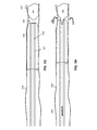
例えば、図1Aは、本明細書に記載の装置の一部を形成し得るカテーテルの一変形例を示している。この例では、カテーテル100が、遠位端105を含む遠位端領域103を備える。この遠位端領域は柔軟性(デュロメータ、例えばショアデュロメータで測定される柔軟性)が高いが、最も遠位の先端(遠位端開口を含む遠位端105)は、その直ぐ近位側の領域よりも実質的に柔らかくなくてもよい。このため、カテーテルの遠位先端領域(例えば、最も遠位の線形寸法x、ここでxは10cm、7cm、5cm、4cm、3cm、2cm、1cm、9mm、8mm、7mm、6mm、5mm、4mm、3mm)は、近位端から遠位端へと柔軟性が高く/硬度が低くなるが、最も遠位の端部領域107(例えば最も遠位の線形寸法zとして測定、ここでzは1cm、9mm、8mm、7mm、6mm、5mm、4mm、3mm、2mm、1mm、0.8mm、0.5mm、0.3mm、0.2mm等であり、zは常にxの少なくとも1/3未満)はそのすぐ近位側の領域より硬度が高く、それは遠位先端領域の最も近位の領域と同じ硬度かより硬くてもよい。
For example, FIG. 1A shows a variant of a catheter that may form part of the device described herein. In this example, the
例えば、図1Aは、本明細書に記載の装置の一部を形成し得る細長い反転支持体のカテーテルの一変形例を示している。この例では、細長い反転支持体がカテーテル100を含み、このカテーテルが、遠位端105を含む遠位端領域103を備える。この遠位端領域は柔軟性(デュロメータ、例えばショアデュロメータで測定される柔軟性)が高いが、最も遠位の先端(遠位端開口を含む遠位端105)は、その直ぐ近位側の領域よりも実質的に柔らかくなくてもよい。このため、カテーテルの遠位先端領域(例えば、最も遠位の線形寸法x、ここでxは10cm、7cm、5cm、4cm、3cm、2cm、1cm、9mm、8mm、7mm、6mm、5mm、4mm、3mm)は、近位端から遠位端へと柔軟性が高く/硬度が低くなるが、最も遠位の端部領域107(例えば最も遠位の線形寸法zとして測定、ここでzは1cm、9mm、8mm、7mm、6mm、5mm、4mm、3mm、2mm、1mm、0.8mm、0.5mm、0.3mm、0.2mm等であり、zは常にxの少なくとも1/3未満)はそのすぐ近位側の領域より硬度が高く、それは遠位先端領域の最も近位の領域と同じ硬度かより硬くてもよい。
For example, FIG. 1A shows a variant of an elongated inverted support catheter that can form part of the device described herein. In this example, the elongated inverted support comprises a
図1Aに示すように、細長い反転支持体は、カテーテルが遠位環状部(遠位端開口)を越えて引っ張られたときに座屈を防止するのに十分な柱強度を有する細長い中空カテーテルである。このため、神経血管用途において、500gまたはそれ未満の圧縮力(例えば、少なくとも約700g、600g、500g、400g、300gなどの圧縮力)が加えられたときに、崩壊(例えば、座屈)しないように、細長い反転支持体を構成することができる。末梢血管用途では、細長い反転支持体が、少なくとも1500gの圧縮力(例えば、少なくとも約2000g、1900g、1800g、1700g、1600g、1500g、1400gなどの圧縮力)に耐えるように選択または構成されるようにしてもよい。一般に、本明細書に記載の装置の何れかは、全長カテーテルではない細長い反転支持体を含むことができるが、典型的には遠位端において、(図7A−図8Dを参照して以下に詳述するように)ロッド、ワイヤまたはハイポチューブなどに連結されたカテーテルの一部を含むことができ、あるいは表面が取り除かれるものであってもよい。このため、本明細書に記載の装置および方法の何れかは、カテーテルに限定されない細長い反転支持体であって、カテーテルの一部を含む細長い反転支持体、あるいは遠位端に環状部を形成するリングまたは他の構造を含む細長い反転支持体とともに使用するように構成されるものであってもよい。図1Aでは、細長い反転支持体のカテーテル100を、任意の適切なタイプのカテーテルまたはカテーテルの一部とすることができ、それには、神経血管への使用に適したマイクロカテーテルが含まれる。
As shown in FIG. 1A, the elongated inversion support is an elongated hollow catheter with sufficient column strength to prevent buckling when the catheter is pulled over the distal annulus (distal end opening). be. Therefore, in neurovascular applications, when a compressive force of 500 g or less (for example, a compressive force of at least about 700 g, 600 g, 500 g, 400 g, 300 g, etc.) is applied, it does not collapse (for example, buckling). In addition, an elongated inverted support can be constructed. For peripheral vascular applications, the elongated inversion support is selected or configured to withstand at least 1500 g of compressive force (eg, at least about 2000 g, 1900 g, 1800 g, 1700 g, 1600 g, 1500 g, 1400 g, etc.). You may. In general, any of the devices described herein can include an elongated inverted support that is not a full length catheter, but typically at the distal end (see FIGS. 7A-8D below). It can include a portion of the catheter connected to a rod, wire, hypotube, etc. (as described in detail), or may have its surface removed. Thus, any of the devices and methods described herein is an elongated inverted support, not limited to a catheter, that forms an elongated inverted support that includes a portion of the catheter, or an annular portion at the distal end. It may be configured for use with an elongated inverted support that includes a ring or other structure. In FIG. 1A, the elongated
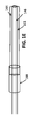
いくつかの変形形態では、細長い反転支持体の遠位端105が、捕捉(拘束、妨害)されることなく、または実質的な摩擦なしに、トラクタがスライドし、またはカテーテルの遠位端で折り返して反転するように適合される。例えば、いくつかの変形例では、遠位先端(端部)が、図1Bに示すように、特に外面(例えば、外径部から内径部への移行部)において、湾曲していてもよいし、またはアール部109としてもよい。
In some variants, the
図1Cは、プラー146に連結された可撓性トラクタ144の一例を示している。この例では、引っ張り可能なトラクタアセンブリ140を形成するために、トラクタがプラーと一体化されて、アセンブリを形成するものとして示されている。図1Cでは、トラクタが、可撓性を有し細長い材料のチューブ(例えば、織られた、編まれた、あるいは編組されたチューブなど)である。トラクタは、第1の構成では、プラーから延びるものとして示されている。この第1の構成の可撓性トラクタの弛緩された外径部が、細長い反転支持体のカテーテルの外径部より大きい外径を有し、反転前にトラクタがその中に配置されることが、特に有益となる場合がある。可撓性で管状のトラクタ144は、細長い反転支持体の遠位開口で容易に折り返して、折り畳むことができるように、十分に柔らかく可撓性を有する(例えば、崩壊強度が低い)ものであってもよい。プラー146は、典型的には、より拡張性が低い(または非拡張性の)構造(チューブ、プラーなど)であってもよい。図1Cに示す例では、トラクタ144が、例えば、形状固定(熱固定など)により、弛緩された第1の構成では、図1Dに示すように、拘束されていないときの細長い反転支持体のカテーテルの内径の直径の1.1〜10倍の半径方向直径に拡張するように構成されている。図1Dでは、図1Cのトラクタが、拡張した弛緩構成で示されている。このため、拡張可能なトラクタは、開くように付勢されるようにしてもよい。トラクタは、メッシュ、織られた、編まれた、編組された、またはシートの材料から形成することができ、通常は、除去される対象物(例えば、血栓)を掴むように構成される。
FIG. 1C shows an example of a
図1Cおよび図1Dでは、トラクタおよびプラーが、2つの部分、すなわちトラクタ144と、プラー146を含む、拡張の小さい(または拡張不可能な)近位部分とを有する。プラーは、ワイヤ、カテーテルまたはハイポチューブなどの別個の領域とすることができ、例えば、遠位端またはその近傍で、トラクタ(例えば、可撓性メッシュ、織物、編組など)の端部領域に連結されている。カテーテルの遠位端開口で折り返されて反転するトラクタの反転領域は、トラクタの遠位対向領域と呼ばれ、折り返し時に血栓を能動的に掴むことができる。
In FIGS. 1C and 1D, the tractor and puller have two parts, namely the
図1Eでは、図1Cの可撓性トラクタが、細長い反転支持体101のカテーテルの遠位端でそれ自体が二重に折り返されたトラクタで示されている。遠位端領域は、例えばプラーおよび細長い反転支持体上で潰れて、潰れた状態で保持される。この例では、細長い反転支持体の外径部上に潰れたトラクタを保持するために、トラクタ保持部188を使用することができる。しかしながら、拘束されていない構成または展開された構成では、図1Fに示すように、この第2の構成のトラクタ(例えば、カテーテルの遠位端で折り返された部分)が、細長い反転支持体のカテーテルの外径部よりも大きい外径を有する。このため、トラクタ144が、装置の細長い反転支持体のカテーテルの内径(ID)より大きい(図1Cに示すような)第1の構成における弛緩した拡張構成と、カテーテルのODよりも大きいODを有する、カテーテルで反転した(図1Fに示す)第2の構成における弛緩した拡張構成とを有するように、トラクタが付勢されるものであってもよい。トラクタは拡張可能であり、プラーに連結することができる。いくつかの変形例では、可撓性トラクタとプラーが同じ材料を含むことができるが、トラクタはより可撓性および/または拡張性があり、あるいはプッシュ/プルワイヤまたはカテーテルに接続することができる。
In FIG. 1E, the flexible tractor of FIG. 1C is shown as a tractor that itself is doubly folded at the distal end of the catheter of the elongated
図1Gおよび図1Hは、図1Aおよび図1Eの構成要素から組み立てられた装置のような装置を使用して血栓を除去することを示している。この例では、装置が、細長い反転支持体101のカテーテルと、当該カテーテルの遠位端領域上に延びてカテーテルの遠位端上でそれ自体が二重に折り返されて反転する可撓性トラクタとを含む血栓除去装置として構成され、外部トラクタの端部領域が、カテーテル内で近位方向に延びてガイドワイヤを通す内部ルーメンを形成する内部の拡張の少ない(この例では、まったく拡張しないものも、拡張の少ないものに含まれる)第2の遠位端領域146(プラー)と連続している。プッシャ/プラー部材は、トラクタの遠位端領域に連続するロッドまたは他の部材であってもよい。図1Gには、装置が、血管160内の血栓155の近くに配置および展開されることが示されている。血栓は、矢印180で示すように、トラクタ140を近位方向にカテーテル101内へと引っ張ることによって、カテーテル内へと引き込まれ、これは、(例えば、図示省略のハンドルを使用して)可撓性トラクタの内側部分の引っ張ることにより、カテーテルの端部開口でトラクタがカテーテルの遠位端内へと折り返されて拡張可能な遠位端領域が反転し、矢印182で示すように、カテーテル内に引き込まれることを示している。カテーテルの外側のトラクタの端部は、カテーテルの外壁に対して「自由」であってもよい。図1Iは、プラー156に連結されたトラクタ144を含むトラクタアセンブリ154の別の例を示している。この例のプラーは、テーパが付けられており(先細り領域161を有し)、その結果、近位端領域とは異なる可撓性を有する遠位端領域を備えることができる。例えば、トラクタが連結される細い直径の遠位端領域195よりも、近位端領域の可撓性を低くすることができる。アセンブリは、放射線不透過性マーカ165を含む。トラクタは、任意の適切な手段によってプラーに取り付けることができる。例えば、トラクタは、プラーに対して、典型的には永久的に、圧着し、接着し、融合し、または他の方法で取り付けることができる。
1G and 1H show that a device such as a device assembled from the components of FIGS. 1A and 1E is used to remove the thrombus. In this example, the device is a catheter with an
これらの装置は、作動前および作動中の両方において、可撓性が高いものであってもよい。例えば、一般に、可撓性トラクタは、特に神経血管系の曲がりくねった血管内での操作性に影響を及ぼさないように、カテーテル、特にカテーテルの遠位端領域の剛性/柔軟性を過度に大きくしないようにしてもよい。本明細書には、カテーテルの最後のycm(例えば、最も遠位の20cm、18cm、15cm、12cm、10cm、9cm、8cm、7cm、6cm、5cm、4cm、3cm、2cm、1cmなど)の剛性の増加が所定のパーセンテージ未満(例えば、10%、12%、15%、18%、20%、25%、30%未満など)である可撓性トラクタチューブ部分が記載されている。例えば、本明細書には、カテーテルを通ってカテーテルの遠位端で二重に折り返される可撓性トラクタチューブ部分が記載されているが、そのカテーテルの遠位5cmの剛性の増加は、カテーテルを通ってカテーテルの遠位端で二重に折り返される可撓性チューブがない場合のカテーテルの遠位5cmの剛性の15%未満である。 These devices may be highly flexible both before and during operation. For example, in general, flexible tractors do not excessively increase the stiffness / flexibility of the catheter, especially the distal end region of the catheter, so as not to affect maneuverability, especially within the winding vessels of the neurovascular system. You may do so. As described herein, the stiffness of the last ycm of the catheter (eg, the most distal 20 cm, 18 cm, 15 cm, 12 cm, 10 cm, 9 cm, 8 cm, 7 cm, 6 cm, 5 cm, 4 cm, 3 cm, 2 cm, 1 cm, etc.) Flexible tractor tube portions where the increase is less than a predetermined percentage (eg, less than 10%, 12%, 15%, 18%, 20%, 25%, 30%, etc.) are described. For example, the present specification describes a flexible tractor tube portion that is doubly folded back at the distal end of the catheter through the catheter, but an increase in rigidity of 5 cm distal to the catheter makes the catheter. Less than 15% of the rigidity of 5 cm distal to the catheter in the absence of a flexible tube that is doubly folded back at the distal end of the catheter through.
トラクタがカテーテルの外面上に延在するようにトラクタがカテーテルの遠位端で少なくとも部分的に反転されている本明細書に記載の装置の何れかにおいては、トラクタがカテーテルの外径部に取り外し可能に連結され、それにより、装置を展開して血栓または他の要素を血管から除去する前に、身体の曲がりくねった血管を含む身体を通して装置を挿入することが可能となっている。トラクタは、織られた、編まれた、あるいは編組された材料のチューブとして、それらをカテーテルの遠位端で折り返すことができ、代替的には、トラクタは、それが通る開口を含む材料のシートから形成されるものであってもよい。 In any of the devices described herein in which the tractor is at least partially inverted at the distal end of the catheter such that the tractor extends over the outer surface of the catheter, the tractor is removed to the outer diameter of the catheter. It is connectable so that it is possible to insert the device through the body, including the winding blood vessels of the body, before deploying the device to remove blood clots or other elements from the blood vessels. The tractor can be folded back at the distal end of the catheter as tubes of woven, woven or braided material, in the alternative the tractor is a sheet of material containing the opening through which it passes. It may be formed from.
本明細書に記載の装置の何れかは、例えばトラクタ保持部(例えば、ハウジング、ロック、クランプなど)などを含むことにより、細長い反転支持体に対しておよび/または相対的に、トラクタの外側端部を固定して、トラクタの早過ぎる展開を防止するように構成されるものであってもよい。例えば、トラクタ保持部は、カテーテルに対してトラクタの外側端部を固定することができ、プラーにより近位方向に引っ張られたときに、トラクタはカテーテル内へと反転する。 Any of the devices described herein includes, for example, a tractor holder (eg, a housing, lock, clamp, etc.) and / or relative to the elongated inverted support and / or relative to the outer edge of the tractor. The portions may be fixed to prevent premature deployment of the tractor. For example, the tractor retainer can secure the lateral end of the tractor to the catheter and the tractor flips into the catheter when pulled proximally by the puller.
早過ぎる展開の一例が、図2A−図2Cに示されている。例えば、図2Aでは、トラクタ200がガイドワイヤ205を介して血栓255へと案内されている(代替的には、ガイドワイヤを使用せずに装置を送達することができる)。この例では、装置が、カテーテル210の上および中に延びるトラクタ203を含む。トラクタの内側端部は、(この例では内側カテーテルとして示される)プラー207に接続されている。カテーテルの外側端部211は拘束されておらず、カテーテルの外径部上に僅かに拡張する状態で示されている。図2Bに示すように、装置が血栓に向かって遠位方向に前進するときに、トラクタが、展開されることにより、カテーテル内に早期に追い込まれ、カテーテルの外側にある、血栓の捕捉のために折り返すことができるトラクタの長さを短くする。さらに、拘束されていないトラクタの外側端部が、装置の正確な位置決めを妨げることもある。図2Cは、トラクタ315のローリングを損なう早過ぎる展開を示している。トラクタの展開が早過ぎると、トラクタを血管内で前後に動かして配置することにより、図2Cに示すように、展開時に血管に接触する可能性のあるトラクタが折れ曲がり、あるいはもつれることがある。
An example of premature deployment is shown in FIGS. 2A-2C. For example, in FIG. 2A, the
一般に、本明細書に記載の装置は、標的位置へのカテーテルのアクセス中に、カテーテルの外側、例えば外径部上でのトラクタの早過ぎる動作を防止するように構成されている。 Generally, the devices described herein are configured to prevent premature movement of the tractor on the outside of the catheter, eg, on the outer diameter, during access of the catheter to a target location.
本明細書に記載の変形例の何れかは、カテーテルの外径部に対して保持されるトラクタの部分にわたり、トラクタ上に、またはトラクタとカテーテルとの間に、粘着性、粘性または接着性の材料を含むトラクタ保持部を含むことができる。例えば、図4A−図4Cに示すように、この装置は、カテーテル上に巻き付けられるトラクタの端部(例えば、トラクタの最も近位側の端部と呼ばれることもあるトラクタの外側端部)に含浸されたシリコーンのような粘着物質を含むことができる。粘着性材料は、トラクタの外側部分の長さに沿ったトラクタの小さい部分(例えば、近位端またはその近傍の局所的領域および/または離散した領域、またはスポット、バンドなどを含むパターン)に含浸されるようにしてもよい。粘着性領域の存在は、カテーテルに対するトラクタ(例えば、織られた、編まれたトラクタなど)の早過ぎる滑りを防止することができる。例えば、トラクタがカテーテルの遠位端開口の周りに引っ張られる前に、親水性のコーティングで覆われていないカテーテルのセクションの上または上方にシリコーン含浸組紐を載置することができ、それが、トラクタが時期尚早にカテーテル上を滑り、あるいはカテーテルから滑り落ちるのを防止する助けとなる。上述したように、粘着性(例えば、接着性、粘性などの)領域は、トラクタ全体において、トラクタの内面(例えば、カテーテルの外径部上に適用されるときのカテーテルを向く面)のみに、トラクタの内面と外面の両方に、かつ/またはカテーテルの外側のトラクタの部分の離散した位置(パターンを含む)に、存在させることができる。例えば、装置は、トラクタの近位端の長さにわたって配置された粘着性材料の複数の領域を含むことができる。いくつかの変形例では、粘着性材料がパターンで配置される。利用される材料は、カテーテルに対して粘着性である(例えば、カテーテルとトラクタとの間に一時的でかつ/または取り外し可能な固定を生じさせるもの)と云うことができる。いくつかの変形例では、粘着性材料をカテーテルの外径部にコーティングまたは塗布することができる。パターンで(例えば、トラクタおよび/またはカテーテルのOD上に)配置される場合、トラクタ(および/またはカテーテル)上の粘着性材料位置のパターンは、トラクタの長さ方向に沿って複数の非連続的な位置に配置されるものであってもよい。パターンには、ストライプ、螺旋、リング、スポットなどが含まれる。 Any of the variants described herein are sticky, viscous or adhesive over the portion of the tractor held against the outer diameter of the catheter, on the tractor or between the tractor and the catheter. A tractor holder containing the material can be included. For example, as shown in FIGS. 4A-4C, the device impregnates the end of the tractor wrapped around the catheter (eg, the outer end of the tractor, sometimes referred to as the most proximal end of the tractor). It can contain a sticky substance such as silicone. The adhesive material impregnates a small portion of the tractor along the length of the outer portion of the tractor (eg, a pattern containing local and / or discrete regions at or near the proximal end, or spots, bands, etc.). It may be done. The presence of the sticky area can prevent the tractor (eg, woven, woven tractor, etc.) from slipping prematurely against the catheter. For example, a silicone impregnated braid can be placed on or above a section of the catheter that is not covered with a hydrophilic coating before the tractor is pulled around the distal end opening of the catheter, which is the tractor. Helps prevent premature slipping on or off the catheter. As mentioned above, the sticky (eg, adhesive, viscous, etc.) region is only on the inner surface of the tractor (eg, the surface facing the catheter when applied over the outer diameter of the catheter) throughout the tractor. It can be present on both the inner and outer surfaces of the tractor and / or at discrete locations (including patterns) on the outer portion of the tractor of the catheter. For example, the device can include multiple regions of adhesive material arranged over the length of the proximal end of the tractor. In some variants, the adhesive material is arranged in a pattern. The material utilized can be said to be sticky to the catheter (eg, one that results in a temporary and / or removable fixation between the catheter and the tractor). In some variations, the adhesive material can be coated or applied to the outer diameter of the catheter. When placed in a pattern (eg, on the OD of the tractor and / or catheter), the pattern of adhesive material positions on the tractor (and / or catheter) is multiple discontinuous along the length of the tractor. It may be arranged at various positions. Patterns include stripes, spirals, rings, spots and the like.
代替的または追加的には、トラクタを他の方法によりカテーテルの外側に一時的に固定して、カテーテルの外径部(OD)に対するトラクタの一時的な固定を提供するようにしてもよい。例えば、トラクタとカテーテルの外径部ODとの間に一時的な固定を与え、ユーザがトラクタを引っ張ってカテーテル先端の周りにトラクタを引っ張るなどして、トラクタに軸方向の張力が加えられるときに、トラクタとカテーテルのODとの間の一時的な固定(一時的な結合、一時的な固定など)を解除して、編組をカテーテルに対してスライドさせることができる。トラクタとカテーテルとの間の粘着性材料の使用に代えて、またはそれに加えて、トラクタとカテーテルのODとの間の一時的な固定は、トラクタおよび/またはカテーテル上の親水性コーティング、および/またはカテーテルとトラクタとの間のスポット(マイクロスポットを含む)結合を含むことができる。 Alternatively or additionally, the tractor may be temporarily fixed to the outside of the catheter by other means to provide temporary fixation of the tractor to the outer diameter (OD) of the catheter. For example, when axial tension is applied to the tractor, for example by providing a temporary fixation between the tractor and the outer diameter OD of the catheter and the user pulling the tractor to pull the tractor around the tip of the catheter. The braid can be slid relative to the catheter by releasing the temporary fixation (temporary coupling, temporary fixation, etc.) between the tractor and the catheter OD. Instead of or in addition to the use of adhesive material between the tractor and the catheter, temporary fixation between the tractor and the catheter OD is a hydrophilic coating on the tractor and / or the catheter, and / or It can include a spot (including microspot) bond between the catheter and the tractor.
例えば、トラクタ(例えば、トラクタの内側面)および/またはカテーテルのOD上の親水性表面をコーティングとして適用することができる。トラクタは、カテーテル上に予め組み立てられていてもよく、親水性/疎水性表面が、カテーテルとトラクタとの間の一時的な固定を提供するようにしてもよい。親水性コーティングの層(または2つの隣接する層)は、トラクタをカテーテルのODに固定することができるとともに、装置が身体の血管/内腔を通って標的位置に至るのを助けることができ、その後、トラクタは、引っ張ってトラクタの表面とカテーテルのODの表面を分離することにより、展開させることができ、トラクタが、血栓と係合して血栓を装置内に引き込むように、遠位端開口を自由に折り返すことを可能にする。いくつかの変形例では、親水性コーティングをトラクタおよび/またはカテーテルに別々に適用することができる。例えば、カテーテルのODおよびトラクタを、別個に親水性コーティングでコーティングした後、組み立てるようにしてもよい。装置が(例えば、カテーテルの遠位端領域でかつカテーテル内で、トラクタを反転させて)組み立てられると、両方のサブアセンブリ(例えば、トラクタとカテーテル)上のコーティングが互いに冷流(cold flow)を生じ得る。アセンブリがカテーテルのアクセス中に体内で濡れたとき、かつ除去すべき標的血栓に近づくとき、ユーザは(トラクタの内側端部に取り付けられたプラーを引っ張ることにより)トラクタを近位方向に引っ張ることができ、それによりカテーテルのODに対してトラクタをスライドさせてトラクタ保持部を解放することができる。 For example, a hydrophilic surface on the tractor (eg, the inner surface of the tractor) and / or the catheter can be applied as a coating. The tractor may be pre-assembled on the catheter and the hydrophilic / hydrophobic surface may provide temporary fixation between the catheter and the tractor. A layer of hydrophilic coating (or two adjacent layers) can secure the tractor to the OD of the catheter and help the device reach the target location through the blood vessels / lumens of the body. The tractor can then be deployed by pulling to separate the surface of the tractor from the surface of the catheter OD so that the tractor engages with the thrombus and pulls the thrombus into the device at the distal end. Allows you to fold back freely. In some variants, the hydrophilic coating can be applied separately to the tractor and / or catheter. For example, the catheter OD and tractor may be separately coated with a hydrophilic coating before assembly. When the device is assembled (eg, in the distal end region of the catheter and within the catheter, with the tractor inverted), the coatings on both subassemblies (eg, the tractor and the catheter) colld flow with each other. Can occur. When the assembly gets wet in the body during catheter access and approaches the target thrombus to be removed, the user can pull the tractor proximally (by pulling on the puller attached to the medial end of the tractor). It can, which allows the tractor to slide relative to the OD of the catheter to release the tractor retainer.
代替的には、トラクタ保持部は、トラクタをカテーテルのODにスポット接合または選択的接合することによって形成することができる。スポット接合またはマイクロ接合は、カテーテルのアクセス中のカテーテルのODに対するトラクタの早過ぎるスライドを防止するのに十分となり得る。例えば、スポット接合または複数のマイクロ接合は、熱接合(溶融)または接着剤を塗布してトラクタをカテーテルのODに付着させることによって形成することができる。マイクロ接合は、上述したように、編組の長さに沿った複数の位置で周方向に、または編組/カテーテルの接触長さに沿って連続的に、または任意の他のパターンで、配置することができる。 Alternatively, the tractor retainer can be formed by spot-joining or selectively joining the tractor to the OD of the catheter. Spot or microjunction may be sufficient to prevent premature sliding of the tractor with respect to catheter OD during catheter access. For example, spot bonding or multiple microbonds can be formed by thermal bonding (melting) or by applying an adhesive to attach the tractor to the OD of the catheter. Microjunctions may be placed at multiple locations along the length of the braid, circumferentially, or continuously along the contact length of the braid / catheter, or in any other pattern, as described above. Can be done.
図4Aは、トラクタ406をカテーテルの外径部に一時的に固定するために使用することができる熱可塑性ポリウレタン(TPU)404の一例を示しており、定位置にあるときに、カテーテルの遠位端(カテーテルの内部)を近位方向に引っ張ることができ、それにより、材料(この例ではペラタン)が破壊されるとともに、トラクタが解放され、その結果、トラクタをカテーテルで遠位方向に折り返して血栓をカテーテル内に引き込むことができる。この例では、壊れ易い(例えば、破壊可能な)材料が、カテーテルおよび/またはトラクタ(この例では、編組トラクタ)上の、親水性コーティングを含まない領域上にコーティングされる。例えば、壊れ易い材料は、親水性コーティングからマスクされた(コーティングされていない)領域にわたって塗布することができる。
FIG. 4A shows an example of a thermoplastic polyurethane (TPU) 404 that can be used to temporarily secure the
図4Bおよび図4Cには、機械的な血栓除去装置400,400’の例が示されており、各々が外側カテーテル409およびトラクタを有し、トラクタが、カテーテルの遠位端領域上に延び、カテーテルの遠位端開口(環状部411)でカテーテル内へと反転して、そこでプラー407に接続される。図4Bに示すように、トラクタの外側端部をカテーテルの外径部上の領域に係合させる粘着性(例えば、親水性)領域414によって、トラクタはカテーテルの外径部に取り外し可能に接着されている。このため、トラクタをカテーテル内で近位方向に引っ張り、上述したように(例えば、図3Cに示すように)トラクタを遠位端開口で内側に折り返すために、初期展開力閾値(例えば、0.5N〜50N)が必要になることがある。力が加えられて、トラクタが展開されることにより、外側面上で遠位方向へと軸方向に動いて、折り返されて、反転して、カテーテル内に入ると、ローリングを継続するのに必要な力が実質的に(例えば、展開力閾値が、装置を折り返すのに必要な力の1.1倍、1.2倍、1.5倍、1.7倍、2倍、3倍、4倍、5倍、10倍またはそれ以上)となり得る。
4B and 4C show examples of
同様に、図4Cに示すように、装置は、トラクタの外側端部に複数のスポット取付部424を含むことができる。上述したように、それらスポットは、トラクタ内(例えば、メッシュ内など)に、またはトラクタとカテーテルの外径部との間に、付着させた接着剤であってもよい。図4Bおよび図4Cの両方に示すように、トラクタは、カテーテルの遠位端領域上に僅かな張力をかけた状態で保持することができ、それによりトラクタの展開および(遠位先端領域での拡張を含む)拡張(図2Aおよび図2Bに示すように、トランペット形状の開口を形成すること)を防止することができる。
Similarly, as shown in FIG. 4C, the device can include a plurality of
代替的または追加的には、本明細書に記載の装置の何れかは、図3A−図3Cおよび図5A−図5Cに示すように、トラクタの外側端部を保持するためのハウジングまたはガレージとして構成されたトラクタ保持部を含むことができる。これらの例では、トラクタ保持部が、カテーテルに沿ってほんの部分的に延び、それにより保持部が、管腔における装置の可撓性および操縦性を増加させることを妨げる可能性がある。図3A−図3Cは、トラクタ保持部303を含む機械的な血栓除去装置300の変形例の使用方法を示している。この例では、トラクタ保持部が、図3Aに示すように、カテーテルの上に配置され、カテーテル307の外径部に対してトラクタ305の外側端部を保持する。トラクタは、プラー309に接続されている。トラクタ保持部は、(例えば、保持部の近位端で)カテーテルに取り付けられてもよいし、カテーテルの上に適用される(例えば、カテーテルおよびトラクタの外側端部の上にシュリンクラップされる)ものであってもよい。装置300は、図示のように、ガイドワイヤ319を介して案内されるようにしてもよく、あるいはガイドワイヤを使用せずに血管360内の血栓355に導かれるようにしてもよい。
Alternatively or additionally, any of the devices described herein can be used as a housing or garage to hold the outer end of the tractor, as shown in FIGS. 3A-3C and 5A-5C. A configured tractor holder can be included. In these examples, the tractor retainer extends only partially along the catheter, which can prevent the retainer from increasing the flexibility and maneuverability of the device in the lumen. 3A-3C show how to use a modified example of the
図3Aに示すように、装置の遠位端が血栓の近くにくると、展開閾値力より大きい力(例えば、図3Cに示すように、トラクタをトラクタ保持部303から引っ張ってトラクタ保持部を後ろに残し、トラクタをカテーテルの遠位端開口で折り返す382のに必要な力)が加えられる。装置は、トラクタの内側端部をプラーで近位方向に引っ張ってトラクタをカテーテル内へと反転させて折り返す間に、遠位方向に前進させることができる。トラクタは、図示のように、血栓を掴み、それをカテーテル内に引き込むことができる。
As shown in FIG. 3A, when the distal end of the device is near the thrombus, a force greater than the deployment threshold force (eg, as shown in FIG. 3C, pulls the tractor from the
同様に、図5A−図5Cに示すように、装置500は、カテーテル509内にある内側端部でプラー507に連結されたトラクタ503を含む。この例では、トラクタの外側端部504が、ガレージまたはハウジングとして構成された保持部501により、カテーテルの外径部に対して固定されている。ハウジングは、所望の展開閾値に応じて、トラクタの端部を軽く保持してもよく、あるいはトラクタをカテーテルに対してよりしっかりと固定してもよい。図5Aに示すように、トラクタ保持部は、1または複数の接合部505によってカテーテルの外径部に固定されている。同様に、図5Bおよび図5Cに示すように、トラクタ保持部は、近位端515で収縮嵌めか、または接着材525の何れかでそれぞれ外径部に固定されている。
Similarly, as shown in FIGS. 5A-5C,
図3A−図3Cおよび図5A−図5Cに示すすべての例において、トラクタ保持部は、カテーテルの長さに沿ってほんの僅かに、例えば数cm(例えば、10cm未満、9cm未満、8cm未満、7cm未満、6cm未満、5cm未満、4cm未満、3cm未満など)延びるものであってもよい。 In all the examples shown in FIGS. 3A-3C and 5A-5C, the tractor retainer is only slightly along the length of the catheter, eg, a few centimeters (eg, less than 10 cm, less than 9 cm, less than 8 cm, 7 cm). It may extend less than, less than 6 cm, less than 5 cm, less than 4 cm, less than 3 cm, etc.).
本明細書に記載の変形例の何れかにおいて、細長い反転支持体は、その軸方向(長手方向)の長さに沿って異なる外径を有することができる。例えば、図1Aに示すカテーテルは、その長さに沿って均一な直径を有するが、他の装置は、図6A−図8Cに示すように、より近位側の領域よりも遠位端領域においてより大きい直径を有するカテーテルを含むことができる。例えば、図6Aに示すように、細長い反転支持体は、近位端よりも遠位端においてより大きい外径を有するカテーテルである。2つの領域間の移行部は、段部605である。このため、環状領域(遠位端開口607)は、遠位端領域と同じ、より大きい外径を有する。図6Bおよび図6Cは、トラクタが外径部上に保持されて、トラクタ保持部により固定されている例を示している。一般に、トラクタがトラクタ上に収縮するように構成されている場合は特に、単純に移行部を有すること、特に、図6Aに示すように、大きい直径の領域と小さい直径の領域との間の急激な移行部(段部を含む)を有することが、トラクタをカテーテル上に固定するのに役立つことがある。図6Bでは、図6Aに示すものと同じカテーテルが、トラクタ603を有し、それが、遠位外径領域に沿って延び、遠位端開口607で反転してカテーテルの内側ルーメン内に入り、そこでプラー609に連結または一体化されている。図6Bに示すように、トラクタの外側端部は、トラクタ保持部613によって定位置に保持され、この例では、トラクタ保持部613が、トラクタを、カテーテルの大きい直径領域への段部に直ぐに隣接するより小さい内径部に対して保持する1または複数のアームとなっている。
In any of the modifications described herein, the elongated inverted support can have different outer diameters along its axial (longitudinal) length. For example, the catheter shown in FIG. 1A has a uniform diameter along its length, whereas other devices, as shown in FIGS. 6A-8C, are in the distal end region rather than the more proximal region. Catheter with a larger diameter can be included. For example, as shown in FIG. 6A, the elongated inverted support is a catheter with a larger outer diameter at the distal end than at the proximal end. The transition between the two regions is the
図6Bに示すように、トラクタ保持部は、近位方向に延びる狭いカテーテル623であり、トラクタが、トラクタ保持部の遠位開口と、より大きい直径のカテーテル601への段部との間で保持されている。トラクタ保持部およびカテーテル601の外側面は、例えば同一の高さを有するように同一面上にあってもよい。図6Bに示すように、トラクタ保持部が、十分に遠くまで(例えば、カテーテルの端部まで、またはカテーテルの端部を越えて)近位方向に延在する場合、それは能動的に係合解除され、展開閾値力を低減し、またはなくすことができる。
As shown in FIG. 6B, the tractor retainer is a
図6Dは、カテーテルに沿って近位方向に一部だけ延びる、図6Cに示したものと同様のトラクタロック633の別の例を示している。これらの変形例の何れかにおいて、トラクタ保持部は、外径部に固定されるようにしてもよく、あるいはカテーテルの外径部に対して移動可能(例えば、スライド可能)であってもよい。
FIG. 6D shows another example of a
図7A−図7Lは、本明細書に記載の装置の何れかの一部として使用することができるカテーテルの様々な変形例を示している。例えば、図7Aは、複数の開口、スロット、穴、窓、スリット709なども含む、より大きい直径の遠位端領域を有するカテーテル700の一例を示している。これらの開口は、後述するように、装置(例えば、細長い反転支持体、プラーおよびトラクタ)が挿入される中間カテーテルとともに使用される場合に特に有用である、使用部位への(薬物を含む)流体の送達、および/または材料の除去、例えば装置を通る真空の利用を可能にする。図7Bは、プラーとトラクタが取り付けられた図7Aの装置を示している。
7A-7L show various variants of the catheter that can be used as part of any of the devices described herein. For example, FIG. 7A shows an example of a
図7Cおよび図7Dは、本明細書に記載の装置の何れかの一部として使用することができるカテーテルの別の変形例を示しており、ここでは複数の切欠領域を有するカテーテルを含む。同様に、図7Eおよび図7Fは、図示のように、大きい近位スカイブ領域を有し、遠位端領域よりも遥かに小さい外径の大部分を残したカテーテルを含む一例を示している。加えて、カテーテルの遠位端は、開口、スロット、切欠領域725などを含むことができる。図7Fは、トラクタ714がプラー713に内側端部で連結された図7Eのカテーテルを示している。プラーは依然としてカテーテルのルーメン内に引き込まれている。同様の例を図7Gおよび図7Hに示すが、細長い反転支持体は、スカイブされる代わりに、ロッド、ポール、ワイヤまたは(図示のような)ハイポチューブに連結される切欠領域725を有するカテーテルから形成される遠位部分を含む。このハイポチューブは、ガイドワイヤルーメンとして、および/または補強部材または支持部材のためのチャネルとして使用することができる。補強部材または支持部材は、トラクタを反転させて折り返すときにトラクタを近位方向に引っ張ることができるように、装置が位置決めされたときに、柱強度を高めることができる。
7C and 7D show another variant of the catheter that can be used as part of any of the devices described herein, including catheters with multiple notched regions. Similarly, FIGS. 7E and 7F show an example including a catheter having a large proximal skive region, leaving most of the outer diameter much smaller than the distal end region, as shown. In addition, the distal end of the catheter can include openings, slots, notched
図7Iおよび図7Jは、カテーテル(図7I)と、カテーテルを含む装置(図7J)の一例を示しており、カテーテルの側面にスロットが設けられ、それにより柱強度を維持しながらも可撓性を高めることが可能となっている。図7Iのカテーテルを含む装置は、トラクタとプラーとともに、図7Jに示されている。 7I and 7J show an example of a catheter (FIG. 7I) and a device containing the catheter (FIG. 7J), which is provided with slots on the sides of the catheter, which is flexible while maintaining column strength. It is possible to increase. The device containing the catheter of FIG. 7I, along with the tractor and puller, is shown in FIG. 7J.
図7Kは、遠位端が、例えばカテーテルの非常に小さい部分から形成された円筒716である細長い反転支持体の一例である。遠位端開口(環状部707)は、図7Lに示すように、トラクタを反転させるために使用されるものであってもよい。細長い反転支持体の細長いシャフト717は、上述したように、ロッド、チューブ、ワイヤなどであってもよい。図7Kの細長い反転支持体を含む図7Lに示す例示的な装置のように、それら装置の何れかに追加の外側カテーテル726を設けることができる。
FIG. 7K is an example of an elongated inverted support whose distal end is, for example, a
また、図8A−図8Dは、ハイポチューブ746(代替的には、ロッド、ワイヤ、小径のカテーテルなどであってもよい)に接合されたリング(例えば、トロイドリング)がこの例では示される、遠位環状部または開口部743を有する細長い反転支持体の別の例を示しており、上述したように、補強部材は、遠位環状部を通って近位方向にトラクタを引っ張る前に、またはその間に、細長い反転支持体の細長い本体内に挿入されるようにしてもよい。図8Bは、図8Aの細長い反転支持体の同様の変形例を示しており、図8Cに示すように、トラクタプラーおよび/またはトラクタを保持することができる支持体の長さ方向に沿って延びる複数のガイド750のみが設けられている。この例では、トラクタ810は、細長い反転支持体の上に延在し、トラクタプラー812によって近位方向に引っ張ることができる。本明細書に記載の装置の何れかにおいて、トラクタプラーは、カテーテルとして示されているが、トラクタプラーは、上述したように、代わりにワイヤ、ハイポチューブなどであってもよい。図8Dは、外側カテーテル809を追加した、図8Cに示すものと同様の装置を示している。
Also, FIGS. 8A-8D show in this example a ring (eg, a toroid ring) attached to a hypotube 746 (alternatively, a rod, wire, small diameter catheter, etc.). Another example of an elongated inverted support with a distal annulus or
解放可能なロック
いくつかの変形例では、トラクタ保持部およびそれが上に適用されるカテーテルの遠位端領域は、上述したトラクタ保持部(例えば、粘着性材料、壊れ易い解放部、ハウジングなど)に加えて、またはその代わりに、解放可能なロックとして構成される(または解放可能なロックを含む)ことができる。例えば、カテーテルは、トラクタの外側(例えば、近位)端部領域上のロック領域(例えば、構造部、内向きの隆起部、粘着性コーティングなど)と係合する、カテーテルの外径部上の摩擦ロック(例えば、隆起、突起、直径拡大部、領域、Oリングなど)を含むトラクタ保持部を含むことができる。トラクタの外側端部上のロック領域は、カテーテルのロック領域がトラクタの下に最初に保持されるように、カテーテルのロック領域(例えば、摩擦隆起部)を近位方向に越えて配置されるものであってもよい。トラクタの内側からトラクタ領域を近位方向に引っ張るために力が加えられると(例えば、ユーザにより展開力が加えられると)、その力は、トラクタロック領域(例えば、くびれ、内向きの突起など)とカテーテルロック領域(例えば、摩擦隆起部、半径方向拡大部、O−リングなど)との間のロック係合に打ち勝つことができ、トラクタを解放して、カテーテルで遠位方向に折り返すことができる。この構成の一例については、図10A−図10Cを参照されたい。この解放可能なロックは、上述した特徴の何れかと組み合わせて使用することができる。図10A−図10Cに示すように、トラクタ1007は、トラクタの外側端部にトラクタロック1006を含む。図10Aは、トラクタとプラー1003のみを示している。図10Bに示す機械的な血栓除去装置1000は、カテーテル1011も含み、カテーテルはトラクタ保持部1009を含む。トラクタ保持部は、トラクタロックと係合し、図10Bに示すように、トラクタ保持部は突起であり、この突起は、トラクタ保持部を越えてトラクタロックを遠位方向に引っ張ることにより、展開閾値を超える十分な力が加えられてトラクタが展開されるまで、トラクタ保持部の近位側にあるトラクタ上のトラクタロックを保持し、展開閾値を超えたときに、トラクタ1007が展開および/または拡張して、カテーテルの遠位端開口で折り返されて血栓を捕獲することを可能にする。
Releasable Lock In some variants, the tractor retainer and the distal end region of the catheter to which it is applied are the tractor retainer described above (eg, adhesive material, fragile release, housing, etc.). In addition to, or instead, can be configured as a releasable lock (or including a releasable lock). For example, the catheter is on the outer diameter of the catheter that engages a locking area (eg, structural, inwardly raised, adhesive coating, etc.) on the outer (eg, proximal) end region of the tractor. It can include a tractor holder that includes friction locks (eg, ridges, protrusions, diameter enlargements, areas, O-rings, etc.). The locking area on the lateral end of the tractor is located proximally beyond the locking area of the catheter (eg, the frictional ridge) so that the locking area of the catheter is initially held under the tractor. It may be. When a force is applied to pull the tractor area proximally from the inside of the tractor (eg, when a deploying force is applied by the user), the force is applied to the tractor lock area (eg, constriction, inward protrusion, etc.). The lock engagement between the and the catheter locking area (eg, frictional ridges, radial enlargements, O-rings, etc.) can be overcome, the tractor can be released and the catheter can be folded distally. .. See FIGS. 10A-10C for an example of this configuration. This releasable lock can be used in combination with any of the features described above. As shown in FIGS. 10A-10C, the
これらの変形例の何れかにおいて、特に本明細書に記載のロックの変形例では、張力は必ずしも必要というわけではないが、トラクタ領域は張力をかけた状態で保持することができる。代替的または追加的には、第2の外側カバーまたはカテーテルが使用されてもよく、または無くてもよい。 In any of these modifications, especially in the lock modifications described herein, tension is not always required, but the tractor region can be held in a tensioned state. Alternatively or additionally, a second outer cover or catheter may or may not be used.
遠位拡張プラーを有する装置
本明細書に記載の変形例の何れかにおいて、プラーは、装置内でトラクタよりも遠位側に延在させることができる。例えば、血栓の捕獲を補助するために、カテーテルまたは装置の残りの部分を越えてより遠位方向に延びるトラクタプラー(例えば、カテーテル、ハイポチューブ、ワイヤなど)の遠位端を有する予め組み立てられた装置を使用することができる。上述したように、これらの変形例の何れかは、例えば血栓を吸引するための真空の使用を含むことができる。真空はプラーを介して加えられるようにしてもよい。吸引を使用して捕獲を開始するときは、血栓をより容易に取り込むことができる。
Device with Distal Expansion Puller In any of the variants described herein, the puller can extend distal to the tractor within the device. For example, pre-assembled with the distal end of a tractor puller (eg, catheter, hypotube, wire, etc.) that extends more distally beyond the rest of the catheter or device to aid in the capture of the thrombus. The device can be used. As mentioned above, any of these variants can include, for example, the use of a vacuum to aspirate the thrombus. Vacuum may be applied via a puller. Thrombi can be more easily taken up when aspiration is used to initiate capture.
例えば、図9Aは、上述したものと同様の機械的な血栓除去装置の一例を示している。トラクタ903はプラー905に接続され、トラクタはカテーテルの外径部901に沿って延びている。いくつかの変形例では、トラクタは、部分的に補強要素と結合、接合または重ね合わせることができ、それにより図9Bおよび図9Cに示すように、ドーザーカテーテルが引っ張られて、アセンブリの遠位端を介して血栓に力/真空を作用させるためにトラクタプラー905の近位端に真空を加えることを許容するときに、トラクタの直径が萎む可能性を低くすることができる。
For example, FIG. 9A shows an example of a mechanical thrombectomy device similar to that described above. The
図9Bに示すように、トラクタは、プラーの遠位端よりも近位側921にあるトラクタプラー905の部分に結合される。このため、プラーを遠位方向に延ばすと、トラクタを反転させる前に、先端がカテーテルの遠位端を越えて延ばすことができる。また、図9Bは(任意選択的な)トラクタ保持部917も示している。
As shown in FIG. 9B, the tractor is coupled to a portion of the
図9Cに示すように、装置は、プラー905の遠位端またはその近傍に取り付けられたストッパ要素を含む。トラクタ上のスライドリング911を使用して、トラクタを引っ張らずにプラーを遠位方向にスライドさせることができる。ストッパ909がスライドリング911と係合するのに十分な距離だけプラーが近位方向に引っ張られたときにのみ、プラーがトラクタを近位方向に引っ張り、カテーテルの遠位端開口でトラクタを反転させ、トラクタを折り返し、血栓物質を引き込むものとなり、それを、プラーを介した真空914の適用によって補助することができる。このため、この構成により、ユーザは、トラクタを遠位方向に引っ張ることなく、カテーテルの遠位端を越える長さでトラクタプラーを遠位方向に延ばすことができる。
As shown in FIG. 9C, the device includes a stopper element attached to or near the distal end of the
図9A−図9Cに示す変形例を含む本明細書に記載の変形例の何れかにおいて、装置は、真空源914に接続するためのバルブ923に連結されるようにしてもよい。図9A−図9Cに示すように、細長い反転支持体(例えば、カテーテル)および/またはプラーに真空を接続することができる。
In any of the modifications described herein, including the modifications shown in FIGS. 9A-9C, the device may be coupled to a valve 923 for connecting to a
本明細書に記載の装置の変形例の何れかは、トラクタのODおよび/またはID、任意のすべてのセクション、および/または細長い反転支持体(例えば、カテーテル)の外径部または内径部に塗布される親水性コーティングなどの潤滑性コーティングを含むことができる。 Any of the modifications of the apparatus described herein are applied to the OD and / or ID of the tractor, any section, and / or the outer or inner diameter of an elongated inverted support (eg, catheter). Lubricating coatings such as hydrophilic coatings to be made can be included.
一般に、本明細書に記載の装置は、外側カテーテルおよびトラクタを介してガイドワイヤおよび/またはより小さいカテーテルの送達を可能にし、それが、(血栓アクセスのための)ガイドワイヤ操作および任意の真空の適用の両方に有用となることがある。さらに、本明細書に記載のトラクタは、軸方向の張力下で外側カテーテルの内側に反転されるときの潰れを最小化し、またはなくすことができ、それにより、カテーテルの遠位先端部における詰まりを防止するとともに、抽出される血栓の量および/または体積を低減することができる。さらに、本明細書に記載のトラクタの何れかは、血栓を掴むのに十分な粗さを有していても、依然として遠位環状部の周りを円滑に折り返すことができる。典型的には、トラクタは、非常に柔軟で滑り易いため、カテーテルトラッキングに悪影響を及ぼすことはない。 In general, the devices described herein allow delivery of guidewires and / or smaller catheters via lateral catheters and tractors, which allow for guidewire operation (for thrombus access) and any vacuum. May be useful for both applications. In addition, the tractors described herein can minimize or eliminate collapse when flipped inward of the lateral catheter under axial tension, thereby clogging the distal tip of the catheter. It can be prevented and the amount and / or volume of thrombus extracted can be reduced. Moreover, any of the tractors described herein can still wrap smoothly around the distal annulus, even if they have sufficient roughness to grab a thrombus. Typically, the tractor is so flexible and slippery that it does not adversely affect catheter tracking.
上述したように、本明細書に記載の予め装着されたトラクタは、血管アクセス中にカテーテルのODに対してスライドしなくてもよい。トラクタは、ユーザがトラクタプラーを引っ張ったときにのみカテーテルのOD上をスライドすることができる。 As mentioned above, the pre-mounted tractors described herein do not have to slide against the OD of the catheter during vascular access. The tractor can slide on the OD of the catheter only when the user pulls on the tractor puller.
一般に、ユーザは、トラクタプラーを固定したまま細長い反転支持体(例えば、カテーテル)を前進させることができ、それにより血栓をカテーテルに引き込むのではなく、血栓を定位置で包み込むことができる。さらに、トラクタは、血栓を効率的に掴み、カテーテルの先端部の周りで良好に折り返されるのを補助するために、望ましい形状に付勢(例えば、熱成形)されるようにしてもよい。一般に、カテーテルの遠位端(先端部)は、(先端部周囲のドーザーの向きを変えることができるようにするために)先端部の直ぐ近位側のカテーテル部分よりも剛性が高くなっている。先端部は、滑らかなコーティングを含むことができる。カテーテル先端部は、トラクタの向きをより容易に変えるために、0.00025インチ超、0.00035インチ超、0.0004インチ超、0.0004インチ超、0.00025インチ超、または0.0005インチ未満の半径を有することができる。例えば、カテーテル先端部の硬度は、72Dより高くてもよく、かつ/または、PTFE、ナイロン、PEEKのようなポリマー材料、ステンレス鋼などで形成されるようにしてもよい。 In general, the user can advance an elongated inverted support (eg, a catheter) with the tractor puller fixed, thereby wrapping the thrombus in place rather than pulling it into the catheter. In addition, the tractor may be urged (eg, thermoformed) into the desired shape to efficiently grab the thrombus and assist in good folding around the tip of the catheter. In general, the distal end (tip) of the catheter is stiffer than the catheter portion just proximal to the tip (to allow the dozer to be oriented around the tip). .. The tip can include a smooth coating. The tip of the catheter is over 0.00025 inches, over 0.00035 inches, over 0.0004 inches, over 0.0004 inches, over 0.00025 inches, or 0.0005 to make it easier to orient the tractor. It can have a radius of less than an inch. For example, the hardness of the catheter tip may be higher than 72D and / or may be made of a polymer material such as PTFE, nylon, PEEK, stainless steel or the like.
いくつかの変形例では、カテーテルの遠位領域(例えば、遠位5cm、10cmなど)が、1/8インチの直径を通るトラッキングを可能にし、また、ドーザー内に引き込んで血栓を掴むときに、例えば100g、200gおよび300gなどの軸方向の圧縮負荷の間、遠位カテーテルの長さの10%未満に制限された軸方向圧縮を有する。 In some variants, when the distal region of the catheter (eg, distal 5 cm, 10 cm, etc.) allows tracking through a diameter of 1/8 inch and also pulls into the dozer to grab a thrombus. It has axial compression limited to less than 10% of the length of the distal catheter during axial compression loads such as 100 g, 200 g and 300 g.
上述したように、これらの装置の何れかは、吸引カテーテルを介したガイドワイヤおよび/またはより小さいカテーテルの送達を可能にすることができる。一般に、トラクタは、張力下にあるときに1.5未満のポアソン比(例えば、1.2未満、1.1未満など)を有するように構成することができる(これは、トラクタがカテーテル先端部に詰まるのを防止するのに役立つ)。 As mentioned above, any of these devices can allow delivery of guide wires and / or smaller catheters via suction catheters. In general, the tractor can be configured to have a Poisson's ratio of less than 1.5 (eg, less than 1.2, less than 1.1, etc.) when under tension (this is because the tractor is at the tip of the catheter). Helps prevent clogging).
本明細書に記載の変形例の何れかにおいて、トラクタおよび/またはカテーテルを放射線不透過性とすることができる。例えば、あるバンドまたは領域を放射線不透過性とすることができる。トラクタ全体を、放射線不透過性とすることができ、例えば、PTまたはタンタル(DFTワイヤ)で満たされたNiTiワイヤを用いてトラクタを形成することができる。代替的には、トラクタの近位端および/または遠位端が、放射線不透過性マーカを有するようにしてもよい。 In any of the variants described herein, the tractor and / or catheter can be radioimpermeable. For example, a band or region can be radioimpermeable. The entire tractor can be radiation opaque and, for example, a NiTi wire filled with PT or tantalum (DFT wire) can be used to form the tractor. Alternatively, the proximal and / or distal ends of the tractor may have radiopaque markers.
本明細書に記載の装置は、脳卒中を予防または治療することを含む、血栓などの物質を除去するために使用され得る。例えば、本明細書に記載の装置は、典型的には非常に曲がりくねった頸動脈のサイホン(siphon)を介して追跡するために使用されるものであってもよい。トラクタは、引っ張られると、依然として血栓を掴んだまま、動きを止めることなく、カテーテルの遠位端の周りを折り返すことができる。上述したように、これらの装置の何れかは、真空と組み合わせて動作するようにしてもよい。真空の使用は不要であることもあるが、特に血栓を最初にトラクタ領域および/またはカテーテルの遠位端に係合させるときに有効となることがある。本明細書に記載の装置の何れかは、カテーテルが血管の内径とほぼ同じ外径を有する場合であっても、あるいはカテーテルが血管内で栓をする場合にも、1.5mm〜3.5mmの範囲のものを含む、多種多様な血管内の血栓を掴むように構成されるものであってもよい。 The devices described herein can be used to remove substances such as thrombi, including preventing or treating stroke. For example, the devices described herein may be those typically used for tracking through a very winding carotid siphon. When pulled, the tractor can fold around the distal end of the catheter, still holding the thrombus and without stopping. As mentioned above, any of these devices may be operated in combination with vacuum. The use of vacuum may not be necessary, but may be particularly effective when the thrombus is first engaged to the tractor region and / or the distal end of the catheter. Any of the devices described herein has a diameter of 1.5 mm to 3.5 mm, even if the catheter has an outer diameter approximately the same as the inner diameter of the blood vessel, or if the catheter plugs in the blood vessel. It may be configured to grab a wide variety of blood clots, including those in the range of.
吸引とともに使用するように構成された装置
上述したように、本明細書に記載の装置の何れかは、血栓を除去するのを補助する吸引力(例えば、吸引)を加えるために真空とともに使用するように構成されるものであってもよい。装置は吸引を使用せずに使用することもできるが、いくつかの例では、本明細書に記載の機械的アテローム切除装置の使用によって血栓除去を補助することができる。さらに、吸引(例えば、単純な可撓性カテーテル、一般に、中間カテーテルと呼ばれる)を使用して血栓を除去するための伝統的な技術は、本明細書に記載の機械的アテローム切除装置の使用によって改善することができる。吸引単独での使用は、しばしば、中間(吸引)カテーテルの詰まりをもたらし、このため、特に曲がりくねった血管においては、血栓全体を除去することが困難となる場合がある。本明細書に記載の装置の何れかは、中間カテーテルとともに使用することができ、また、装置が中間カテーテルのルーメン内にある間に真空を加えることができるようにすることを含む真空血栓除去技術とともに使用することができ、その結果、吸引が中間カテーテルおよび/または装置の遠位端から適用されるとともに、装置が中間カテーテルから遠位方向に延びる間に吸引が適用されるようにすることができる。適用された真空は、最初にガスピングすること、または血栓を掴むことを補助することができる。真空は、装置の遠位端および/または装置とともに使用される中間または外側のカテーテルまたはスリーブ(例えば、細長い反転支持体および反転トラクタ)の遠位端から加えられるようにしてもよい。本明細書には、中間カテーテルまたは外側カテーテルとともに使用するためのものを含む、真空とともに使用するように構成された装置も記載されており、当該装置を、中間カテーテルまたは外側カテーテルを介して血栓へと送達することができる。装置は、外側カテーテル内から血栓を掴むことができ、または中間カテーテルまたは外側カテーテルから遠位方向に拡張することができる。例えば、上述した図7A−図8Dは、以下にさらに詳細に述べるように、上述した任意の装置で使用される細長い反転支持体の例であり、それらの細長い反転支持体は、中間カテーテルから吸引を適用するのに特に適している。
Devices configured for use with suction As mentioned above, any of the devices described herein is used with vacuum to apply a suction force (eg, suction) that assists in removing the thrombus. It may be configured as follows. Although the device can be used without suction, in some cases thrombectomy can be assisted by the use of the mechanical atherectomy device described herein. In addition, traditional techniques for removing thrombi using suction (eg, simple flexible catheters, commonly referred to as intermediate catheters) are by using the mechanical atherectomy device described herein. Can be improved. The use of suction alone often results in clogging of the intermediate (suction) catheter, which can make it difficult to remove the entire thrombus, especially in winding vessels. Any of the devices described herein can be used with an intermediate catheter and is a vacuum thrombectomy technique that allows vacuum to be applied while the device is in the lumen of the intermediate catheter. Can be used with, so that suction is applied from the intermediate catheter and / or the distal end of the device and suction is applied while the device extends distally from the intermediate catheter. can. The applied vacuum can assist in first gasping or grabbing a thrombus. Vacuum may be applied from the distal end of the device and / or the distal end of an intermediate or outer catheter or sleeve (eg, elongated inverted support and inverted tractor) used with the device. Also described herein are devices configured for use with vacuum, including those for use with an intermediate or lateral catheter, which can be transferred to a thrombus via an intermediate or lateral catheter. Can be delivered. The device can grab a thrombus from within the lateral catheter or can be extended distally from the intermediate or lateral catheter. For example, FIGS. 7A-8D described above are examples of elongated inverted supports used in any of the devices described above, as described in more detail below, the elongated inverted supports being aspirated from an intermediate catheter. Especially suitable for applying.
図11Aは、非常に可撓性のある外側/中間カテーテルまたはスリーブが、例えば、ガイドワイヤを用いて装置の遠位端に操作される構成の一例を示している。このため、中間カテーテルは、血栓の近くで、またはそれに隣接して操作されることがある。本明細書に記載のそれら使用方法の何れかと同様に、画像化(蛍光透視法、コントラスト画像化など)を使用することができる。一旦位置決めしたら、ガイドワイヤを除去するか、または定位置に残すことができ、細長い反転支持体および反転トラクタを含む装置を、中間カテーテル/スリーブ内で拡張させることができる。図11Aには、血管4109内で遠位側に配置された中間カテーテル4104が示されている。図面の何れかと同様に、血管内は非常に曲がりくねって分岐している可能性があるが、便宜上、図面では真っ直ぐに示されている。装置4100は、中間カテーテルを通って遠位方向に延び、図示のように、血栓4111を掴むために中間カテーテルの遠位開口の外に延びている。このため、プラー4105を近位方向に(図の左側へ)引っ張って、細長い反転支持体4113のカテーテル部分上からトラクタ4103を引っ張ることができ、それによりトラクタは、反転して細長い反転支持体内へと折り返され、血栓を捕獲して引き込むことができる。血栓は圧縮されるものであってもよい。
FIG. 11A shows an example of a configuration in which a highly flexible outer / intermediate catheter or sleeve is operated, for example, using a guide wire to the distal end of the device. For this reason, the intermediate catheter may be operated near or adjacent to the thrombus. Imaging (fluorescence perspective, contrast imaging, etc.) can be used in the same manner as any of those uses described herein. Once positioned, the guidewire can be removed or left in place and the device, including the elongated inverted support and inverted tractor, can be extended within the intermediate catheter / sleeve. FIG. 11A shows an
このため、この構成は、血管クリーナと呼ぶことができる。血栓を掴んで引っ張るためのトラクタのローリングに加えて、中間カテーテル4121および/または細長い反転支持体4123の一方または両方から加えられる真空によって血栓を引っ張ることができる。真空は、装置が遠位側に(または中間カテーテル内にあっても)配置される前に、または中間カテーテルから遠位方向に拡張された後に、例えば中間カテーテル内に与えることができる。この構成は、図11Aに示すように、外側カテーテルを通してトラクタを血栓の正面に導入することができる。上述したように、機械的な血栓除去装置は、それを遠位方向に押し出すことによって、かつ/または中間カテーテルを引き戻すことによって、中間カテーテルから遠位方向に延ばすことができ、トラクタの全部または一部を図示のように血管内に展開することができる。真空がカテーテルを介して加えられる場合、細長い反転支持体を形成するカテーテルは、このカテーテルを通る吸引を可能にするように覆いを付けるか、またはシールするようにしてもよい。
For this reason, this configuration can be referred to as a vascular cleaner. In addition to rolling the tractor to grab and pull the thrombus, the thrombus can be pulled by a vacuum applied from one or both of the
任意選択的には、外側および/または内側および/またはプラーを介して真空を引くようにしてもよい。その後、前述したように、細長い反転支持体に対してトラクタを近位方向に引っ張って、血栓を引っ張ることができる。その後、血栓を除去したら、中間カテーテルを遠位方向に前進させて、かつ/または機械的な血栓除去装置を近位方向に引き抜いて、装置を取り外すことができる。その後、血栓が除去されたことを確認するために血管造影を行うことができる。 Optionally, a vacuum may be drawn through the outer and / or inner and / or puller. Then, as described above, the tractor can be pulled proximally to the elongated inverted support to pull the thrombus. After removing the thrombus, the intermediate catheter can then be advanced distally and / or the mechanical thrombectomy device can be pulled out proximally to remove the device. Angiography can then be performed to confirm that the thrombus has been removed.
代替的には、図11Bに示すように、中間カテーテルを用いて血栓を除去して、中間カテーテルのルーメン内の(例えば、遠位端の近傍にあるが、遠位端から完全に延びることはない)機械的な血栓除去装置で真空を引くことができる。図11Aで述べたように、図11Bにおいて、中間カテーテルは、遠位端が血栓の近くに配置されるように(例えば、ガイドワイヤを使用して)血管内に挿入されるものであってもよい。吸引は、機械的な血栓除去装置が挿入される前または挿入された後の何れかで、血栓を中間カテーテル内に引き込むために使用することができる。 Alternatively, as shown in FIG. 11B, thrombi can be removed using an intermediate catheter and within the lumen of the intermediate catheter (eg, near the distal end but extending completely from the distal end). No) A mechanical thrombectomy device can be used to draw a vacuum. As mentioned in FIG. 11A, in FIG. 11B, the intermediate catheter is inserted into the blood vessel so that the distal end is located near the thrombus (eg, using a guide wire). good. Aspiration can be used to pull the thrombus into the intermediate catheter either before or after the mechanical thrombectomy device is inserted.
図11Bに示すように、細長い反転支持体4113’は、装置を取り囲む中間カテーテル4104を介して適用される真空とともに使用するのに特に適している。例えば、図11Bでは、細長い反転支持体4113’が、血栓が引き込まれる遠位端開口から数cmだけ延びる遠位カテーテル領域4125を含む。その後、細長い反転支持体は、細長い支持体まで先細りし、細長い支持体は、ワイヤ、ハイポチューブまたはスカイブ領域によって形成することができる。この構成は、カテーテルが中間カテーテルのルーメンを塞ぐことを防止し、それにより、開いた遠位端に到達して血栓を引き込むために吸引を適用する前に、真空の抵抗を増加させることができる。代替的または追加的には、細長い反転支持体のカテーテル部分の外径は、より多くの真空を通過させることができるようなサイズにすることができる。例えば、装置は、カテーテルの外径部と中間カテーテル(「外側カテーテル」)の内径部との間が少なくとも約0.002インチ以上(例えば、0.003,0.004,0.005,0.006インチなど)となるようにサイズ設定することができる。また、これは、細長い反転支持体の遠位端開口上でのトラクタのスムーズなローリングを可能にする。
As shown in FIG. 11B, the elongated inverted support 4113'is particularly suitable for use with vacuum applied via an
操作において、図11Bに示すような血栓を除去する方法は、真空4121を使用して血栓の少なくとも先端部を中間カテーテル内に引き込むステップを含むことができる。典型的には、血栓は中間カテーテル内で詰まる可能性があるが、本明細書に記載の機械的な血栓除去装置は、中間カテーテル内から血栓を除去するために使用することができる。例えば、真空を維持しながら、機械的な血栓除去装置を挿入するようにしてもよく(または、前述したように中間カテーテルに予め組み込むようにしてもよく)、トラクタプラー4105を引っ張って血栓を中間カテーテルおよび血管から引き込み、血栓を圧縮および/または分離して、装置内、すなわち中間カテーテル内に引き込み、そこで、例えば機械的な血栓除去装置を取り除くことによって、血栓を近位方向に引き出すことができる。上述したように、血栓が除去されたことを確認するために、(例えば、より多くの血栓を除去するために機械的な血栓除去装置を再挿入して使用する必要がある場合には、それを定位置に残すことにより)中間カテーテルを介して血管造影を行うことができる。
In operation, the method of removing a thrombus as shown in FIG. 11B can include the step of pulling at least the tip of the thrombus into an intermediate
上述したように、図11Aに示すような完全なカテーテルは、真空が中間容器の遠位端に到達するのを阻止または防止する可能性がある。このため、機械的な血栓除去装置を、図11Bに示すように、中間カテーテルまたはスリーブ内で真空とともに使用できるように構成することが有益となることがある。これは、トラクタが反転する遠位端開口を形成する細長い反転支持体のより大きい直径のカテーテル部分を最小化することによって、上記のように達成することができる。ここで図7A−図8Dを再び参照すると、図7Aにおいては、細長い反転支持体700が、より近位側の領域703よりも大きい直径を有する遠位カテーテル部分701を有し、また、複数の開口、穴、ギャップ、切欠領域、スロット709なども含み、それにより細長い反転支持体を通る真空の流れをより容易なものとすることができる。図示の細長い反転支持体は、図7Bに示すように、トラクタ711が反転する遠位端707も含む。図7Bに示すように、細長い反転支持体が透明であるため、細長い反転支持体内のプラー713およびトラクタを見ることができる。
As mentioned above, a complete catheter as shown in FIG. 11A may prevent or prevent the vacuum from reaching the distal end of the intermediate vessel. For this reason, it may be beneficial to configure the mechanical thrombectomy device for use with vacuum in an intermediate catheter or sleeve, as shown in FIG. 11B. This can be achieved as described above by minimizing the larger diameter catheter portion of the elongated inverted support that forms the distal end opening in which the tractor inverts. Now referring again to FIGS. 7A-8D, in FIG. 7A, the elongated
同様に、図7Bおよび図7Cに示すように、細長い反転支持体の全長は、装置内の真空または他の流体の流れを可能にする能力を高めることができる複数の切欠領域713を含むが、細長い反転支持体が、例えばトラクタを引っ張ることによって加えられる少なくとも500gまでの長手方向の圧縮力に対して潰れに抵抗する柱強度を依然として提供することが可能である。同様に、図7Eおよび図7Fの細長い反転支持体は、その長さ方向に沿って開口709も含む、スカイブされたカテーテルを示している。プラーおよびトラクタ412は、図7Fの細長い反転支持体内に示されている。また、図7Gおよび図7Hは、カテーテルのスカイブされた部分ではなく、細長い反転支持体の遠位カテーテル領域が、カテーテルの遠位端に取り付けられたワイヤ、バー、チューブ721などによって形成される一例を示している。任意選択的には、カテーテルは、開口709も含むことができる。図7Iおよび図7Jの細長い反転支持体は、図示のように、その長さのすべてまたは大部分に沿って(特に、遠位端領域の近傍に)開口709’を含む。
Similarly, as shown in FIGS. 7B and 7C, the overall length of the elongated reversing support includes a plurality of notched
最後に、図7Kに示す細長い反転支持体の変形例は、ワイヤ、バー、チューブ、ハイポチューブ、スカイブ領域717などに接続された最小カテーテル部分(シリンダ716)を含む。
Finally, a variant of the elongated inverted support shown in FIG. 7K includes a minimal catheter portion (cylinder 716) connected to wires, bars, tubes, hypotubes, skive
図8A−図8Dは、同様の最小の細長い反転支持体800の動作を示している。この例では、装置が、細長い支持体を形成するワイヤ、バー、チューブ、ハイポチューブ、スカイブ領域746などにしっかりと結合された遠位開口部743を含む。細長い支持体は、中空であっても(例えば、ガイドワイヤ用のルーメンを含むことができる)、または中実であってもよい。細長い支持体は、図8Bに示すように、1または複数の追加的な支持ガイド750も含むことができる。これらの支持体は、細長い反転支持体内にプラーおよび/またはトラクタを収容するのを助けることができる。本明細書に記載の細長い反転支持体の何れかは、追加的な支持ガイドを含むことができる。図8Bの細長い反転支持体は、図8Cのトラクタ711およびプラー713とともに示されている。上述したように、この変形例は、図8Dに示すように、中間(例えば、「外側」)カテーテル、スリーブ809などとともに使用するのに特によく適している。
8A-8D show the operation of a similar minimal elongated
拡張可能な遠位端
本明細書に記載の機械的な血栓除去装置の何れかは、より小さい直径の開口部(例えば、遠位端開口)からより大きい直径の開口部まで拡張可能な遠位端を有する細長い反転支持体を含むことができる。この拡張は、カテーテル内に血栓を引っ張ることによって行うことができる。例えば、図12A−図12Cは、拡張可能な遠位端を有するカテーテルとして構成された細長い反転支持体の一例の動作を示している。この変形例では、カテーテル遠位端4401は、細長い反転支持体のカテーテルの遠位端において、例えばレーザ切断によって形成または切断されたスロットまたはスリット4403を含むことができる。装置は、上述したように操作されて、図12Bに示すように、血栓の近傍に(例えば、血栓に接触または隣接して)配置されて、プラー上で近位方向に引っ張られてトラクタ4405をカテーテルに引き込むことができる。本明細書に記載の装置は、通常は血栓をかなり圧縮することができるが、半径方向の直径をより緩やかに減少させることによって、圧縮をより簡単にかつ/またはより効率的に行うことができる。図12Bに示すように、トラクタが先端開口部で折り返されて反転すると、トラクタとともに血栓が引き込まれることがある。大きい血栓4413が遠位端開口内に入ると、図12Cに示すように、遠位端開口が拡張して、スロットまたはスリット4403に沿って開くことができ、それにより、遠位端開口がラッパ状に広がる。いくつかの変形例では、エッジがトラクタに引っ掛かるのを防ぐために遠位端を少なくとも部分的に覆うように、弾性スリーブ、ガスケット、リングまたはカバー(図12A−図12Cには図示せず)が含まれるようにしてもよい。例えば、遠位端が開かれて外向きのフレアが形成されるように、弾性層または伸張可能な層が、切断された遠位端を覆うことができる。図12Cには、血栓が引っ張られる漏斗形状を形成する外側に広がった遠位端が示されている。この漏斗形状の開口は、血栓を圧縮して機械的な血栓除去装置内に引き込むのを補助することができる。
Expandable Distal End Any of the mechanical thrombectomy devices described herein is a distal that can be expanded from a smaller diameter opening (eg, a distal end opening) to a larger diameter opening. It can include an elongated inverted support with an end. This dilation can be done by pulling a thrombus into the catheter. For example, FIGS. 12A-12C show the operation of an example of an elongated inverted support configured as a catheter with an expandable distal end. In this variant, the distal end of the
いくつかの変形例では、遠位側を向く端部に漏斗形状を有するか、またはその形状になるように細長い反転支持体を構成することができる。図12A−図12Cに示すように、遠位側を向く端部は、遠位端開口に漏斗形状の口を常に有していてもよく、あるいは遠位端開口は、漏斗形状をとるように構成されるものであってもよい。いくつかの変形例では、細長い反転支持体の遠位端が、直接的に半径方向に弾性であるように構成されているが、近位から遠位の軸に沿って(圧縮荷重において)剛性を維持するように構成されている。例えば、細長い反転支持体の遠位端は、高い圧縮負荷強度を有するが遠位端開口を拡大するために互いに分離してもよい近位から遠位の軸に延びるストランドまたはロッドで構成することができ、例えば、それらがリングによって接続されて、より遠位のリングがより近位のリングよりも弾性/伸縮性の高くなるようにしてもよい。 In some variants, an elongated inverted support can be configured to have or have a funnel shape at the distal end. As shown in FIGS. 12A-12C, the distal end may always have a funnel-shaped mouth at the distal end opening, or the distal end opening should be funnel-shaped. It may be configured. In some variants, the distal end of the elongated inverted support is configured to be directly elastic in the radial direction, but rigid along the proximal to distal axis (at compressive loads). Is configured to maintain. For example, the distal end of an elongated inverted support shall consist of strands or rods extending from the proximal to the distal axis that have high compressive load strength but may be separated from each other to widen the distal end opening. For example, they may be connected by a ring so that the more distal ring is more elastic / elastic than the more proximal ring.
ある構成または要素が別の構成または要素の「上に(on)」あると言及される場合、それは他の構成または要素上に直接存在してもよいし、介在する構成および/または要素が存在してもよい。対照的に、ある構成または要素が別の構成または要素の「上に直接ある」と言及された場合、介在する構成または要素は存在しない。ある構成または要素が他の構成または要素に「接続された」、「取り付けられた」または「結合された」と言及される場合、それは他の構成または要素に直接的に接続、取り付けまたは結合されてもよいし、介在する構成または要素が存在してもよい。対照的に、ある構成または要素が別の構成または要素に「直接的に接続された」、「直接的に接続された」または「直接的に結合された」と言及される場合、介在する構成または要素は存在しない。一実施形態に関して説明または図示された構成および要素は、他の実施形態にも適用することができる。当業者であれば、別の構成に「隣接して」配置された構造または構成への言及は、隣接する構成に重なったり下にある部分を有してもよいことも理解されよう。 When it is mentioned that one configuration or element is "on" in another configuration or element, it may be directly on top of the other configuration or element, and there are intervening configurations and / or elements. You may. In contrast, when one configuration or element is referred to as "directly above" another configuration or element, there are no intervening configurations or elements. When one configuration or element is referred to as "connected," "attached," or "bonded" to another configuration or element, it is directly connected, attached, or combined to another configuration or element. There may be intervening configurations or elements. In contrast, when one configuration or element is referred to as "directly connected," "directly connected," or "directly coupled" to another configuration or element, an intervening configuration. Or the element does not exist. The configurations and elements described or illustrated for one embodiment may also be applied to other embodiments. Those skilled in the art will also appreciate that references to structures or configurations that are "adjacent" to another configuration may have parts that overlap or underlie the adjacent configurations.
本明細書で使用する用語は、特定の実施例のみを説明するためのものであり、本発明を限定するものではない。例えば、本明細書で使用されるように、単数形「a」、「an」および「the」は、文脈がそうでないことを明示しない限り、複数形も含むことが意図される。本明細書で使用される「備える(comprises)」および/または「備えている(comprising)」という用語は、記載された構成、ステップ、動作、要素および/または構成要素の存在を特定するが、他のステップ、動作、要素、構成要素および/またはそれらのグループのうちの1または複数の存在や追加を除外するものではない。本明細書で使用される「および/または」という用語は、関連する列挙された項目の1または複数の任意のおよびすべての組み合わせを含み、「/」と省略することができる。 The terms used herein are for the purpose of describing only specific examples and are not intended to limit the present invention. For example, as used herein, the singular forms "a", "an" and "the" are intended to include the plural unless the context explicitly states otherwise. As used herein, the terms "comprises" and / or "comprising" identify the components, steps, actions, elements and / or the presence of the components described. It does not preclude the existence or addition of one or more of the other steps, actions, elements, components and / or groups thereof. As used herein, the term "and / or" includes any and all combinations of one or more of the related listed items and may be abbreviated as "/".
本明細書では、「下方(under)」、「下(below)」、「より下(lower)」、「上(over)」、「より上(upper)」などのような空間的に相対的な用語は、図示するように、1つの要素や構成の他の要素や構成との関係の説明を容易にするために用いられる。これらの空間的に相対的な用語は、図面に示されている向きに加えて、使用または動作における装置の様々な向きを包含することが意図されていることが理解されよう。例えば、図面内の装置が反転されている場合、他の要素または構成の「下方(under)」や「下(beneath)」と記載された要素は、他の要素または構成の「上に」位置づけられる。したがって、例示的な用語「下方(under)」は、上方および下方の向きの両方を含み得る。装置は他の方向に向いていてもよく(90度または他の向きに回転されてもよい)、本明細書で使用される空間的に相対的な記述子はそれに応じて解釈される。同様に、特に断りのない限り、「上向き」、「下向き」、「垂直」、「水平」などの用語は説明の目的でのみ使用される。 In the present specification, spatially relative such as "under", "below", "lower", "over", "upper", etc. Terms are used to facilitate the explanation of relationships with other elements or configurations of one element or configuration, as illustrated. It will be appreciated that these spatially relative terms are intended to include various orientations of the device in use or operation, in addition to the orientations shown in the drawings. For example, if a device in a drawing is flipped, an element labeled "under" or "beneath" of another element or configuration is positioned "above" the other element or configuration. Be done. Thus, the exemplary term "under" can include both upward and downward orientations. The device may be oriented in the other direction (rotated 90 degrees or in any other direction), and the spatially relative descriptors used herein are interpreted accordingly. Similarly, unless otherwise noted, terms such as "upward", "downward", "vertical", and "horizontal" are used for explanatory purposes only.
「第1の」および「第2の」という用語は、様々な構成/要素(ステップを含む)を説明するために本書で使用されるが、文脈上別段の記載がない限り、これらの構成/要素はこれらの用語によって限定されるべきではない。これらの用語は、ある構成/要素を別の構成/要素と区別するために使用される。したがって、以下に説明する第1の構成/要素は第2の構成/要素とも呼ぶことができ、同様に、以下に説明する第2の構成/要素は本発明の教示から逸脱することなく第1の構成/要素と名付けることができる。 The terms "first" and "second" are used herein to describe various components / elements (including steps), but unless otherwise specified in context, these components / The elements should not be limited by these terms. These terms are used to distinguish one component / element from another. Therefore, the first component / element described below can also be referred to as the second component / element, and similarly, the second component / element described below is the first without departing from the teachings of the present invention. Can be named a component / element of.
本明細書および特許請求の範囲を通じて、文脈上他の意味を要求しない限り、「備える(comprise)」という語および「備える(comprises)」、「備えている(comprising)」などの変形は、様々な構成要素が、方法および物品(デバイスや方法を含む要素および装置)においてともに使用され得ることを意味する。例えば、「備えている(comprising)」という用語は、すべての記載された要素またはステップを含むことを意味するが、他の要素またはステップの除外を意味するものではないと理解される。 Throughout the specification and claims, the word "comprise" and variations such as "comprises" and "comprising" vary, unless contextually requires other meaning. Constituents can be used together in methods and articles (elements and devices including devices and methods). For example, the term "comprising" is understood to mean including all described elements or steps, but not the exclusion of other elements or steps.
一般に、本明細書に記載された装置および方法は何れも包括的であると理解すべきであるが、構成要素および/またはステップのすべてまたはサブセットが代わりに排他的であってもよく、あるいは、様々な構成要素、ステップ、サブコンポーネントまたはサブステップから「なる」または「本質的になる」と表現されるものであってもよい。 In general, all of the devices and methods described herein should be understood to be inclusive, but all or a subset of the components and / or steps may instead be exclusive or, or It may be described as "consisting" or "essentially" consisting of various components, steps, subcomponents or substeps.
本明細書および特許請求の範囲で使用されているように、実施例で使用されているものを含み、そうでないと明記していなければ、特に明記しなくても、すべての数字は、「約」または「およそ」が前にあるものとして解釈される。記載された値および/または位置が、合理的な予想される範囲内の値および/または位置であることを示すために、大きさおよび/または位置を記述するときに、「約」または「およそ」という語句を使用することがある。たとえば、ある数値は、記載された値(または値の範囲)の+/−0.1%、記載された値(または値の範囲)の+/−1%、記載された値(または値の範囲)の+/−2%、記載された値(または値の範囲)の+/−5%、記載された値(または値の範囲)の+/−10%などの値を有しうる。本明細書に記載の様々な値も、文脈が他の意味を示さない限り、約またはおよその値を含むと理解されるべきである。例えば、「10」という値が開示されている場合、「約10」も開示されている。本明細書に列挙された任意の数値範囲は、その中に包含されるすべての下位範囲を含むことが意図される。ある値が開示された場合、当業者によって適切に理解されるように、当該値「以下」、「以上」、および可能性のある値の範囲もまた開示されているものとする。例えば、「X」という値が開示された場合、「X以下」および「X以上」(例えば、Xは数値である)も開示される。また、出願全体を通して、データはいくつかの異なるフォーマットで提供され、このデータはエンドポイントとスタートポイント、およびデータポイントの任意の組み合わせの範囲を表すことも理解される。例えば、特定のデータポイント「10」および特定のデータポイント「15」が開示されている場合、10と15、それ以上、それ以下と同様に、10〜15の間も開示されていると考えられる。また、2つの特定の単位間の各単位も開示されると理解される。例えば、10と15が開示されている場合、11、12、13、および14もまた開示されている。 As used herein and in the claims, all numbers include those used in the Examples, and unless otherwise stated, all numbers are "about." Or "approximately" is interpreted as preceded. When describing the size and / or position to indicate that the value and / or position described is within a reasonable expected range, "about" or "approximately" May be used. For example, a number is +/- 0.1% of the stated value (or range of values), +/- 1% of the stated value (or range of values), the stated value (or of the value range). It can have values such as +/- 2% of the stated value (or range), +/- 5% of the stated value (or range of values), +/- 10% of the stated value (or range of values). The various values described herein should also be understood to include about or approximate values, unless the context indicates other meanings. For example, when the value "10" is disclosed, "about 10" is also disclosed. Any numerical range listed herein is intended to include all subranges contained therein. If a value is disclosed, the value "less than or equal to", "greater than or equal to", and the range of possible values shall also be disclosed, as will be appropriately understood by those skilled in the art. For example, when the value "X" is disclosed, "X or less" and "X or more" (for example, X is a numerical value) are also disclosed. It is also understood that throughout the application, the data is provided in several different formats, and this data represents a range of endpoints and starting points, and any combination of data points. For example, if a particular data point "10" and a particular data point "15" are disclosed, it is believed that they are also disclosed between 10 and 15, as well as above and below. .. It is also understood that each unit between two specific units is also disclosed. For example, if 10 and 15 are disclosed, then 11, 12, 13, and 14 are also disclosed.
様々な例示的な実施形態を記載してきたが、特許請求の範囲に記載された本発明の範囲から逸脱することなく、様々な実施形態に対して多くの変更が可能である。例えば、説明された様々な方法ステップが実行される順序は、代替的な実施形態ではしばしば変更されてもよく、他の代替的な実施形態では、1または複数の方法ステップが完全にスキップされてもよい。様々な装置およびシステムの実施形態の任意の構成は、いくつかの実施形態に含まれてもよく、他の実施形態に含まれなくてもよい。したがって、上記の説明は、主に例示的な目的のために提供され、特許請求の範囲に記載される本発明の範囲を限定するものと解釈されるべきではない。 Although various exemplary embodiments have been described, many modifications can be made to the various embodiments without departing from the scope of the invention described in the claims. For example, the order in which the various method steps described are performed may often change in alternative embodiments, with one or more method steps skipped altogether in other alternative embodiments. May be good. Any configuration of various device and system embodiments may or may not be included in some embodiments. Therefore, the above description is provided primarily for illustrative purposes and should not be construed as limiting the scope of the invention as set forth in the claims.
本明細書に含まれる実施例および図面は、本発明を実施することができる特定の実施例を図示するものであり、限定するものではない。上述したように、本開示の範囲から逸脱することなく、構造的および論理的な置換および変更を行うことができるように、他の実施形態を利用してそこから誘導することができる。本発明の主題のそのような実施形態は、実際に1より多くが開示されていても、本出願の範囲を任意の単一の発明または発明の概念に自発的に限定しようとするものではなく、単に「発明」という用語によって個々にまたは集合的に言及されてもよい。したがって、特定の実施形態を本明細書で図示および説明したが、同じ目的を達成するために計算された任意の構成を、示された特定の実施形態に置き換えることができる。本開示は、様々な実施形態の任意のおよびすべての適合または変形を網羅することを意図している。上記実施形態の組み合わせ、および本明細書に具体的に記載されていない他の実施形態は、上記の説明を検討すると当業者には明らかであろう。
The examples and drawings contained herein illustrate, but are not limited to, specific examples in which the present invention can be practiced. As mentioned above, other embodiments can be utilized to derive from it so that structural and logical substitutions and modifications can be made without departing from the scope of the present disclosure. Such embodiments of the subject matter of the present invention do not attempt to voluntarily limit the scope of the present application to any single invention or concept of the invention, even if more than one is actually disclosed. , May be referred to individually or collectively by the term "invention". Thus, although specific embodiments have been illustrated and described herein, any configuration calculated to achieve the same objective can be replaced with the specific embodiments shown. The present disclosure is intended to cover any and all adaptations or variations of various embodiments. Combinations of the above embodiments, and other embodiments not specifically described herein, will be apparent to those skilled in the art upon examination of the above description.
Claims (5)
近位端、遠位端および遠位端開口を有するカテーテルと、
可撓性チューブを含むトラクタであって、前記可撓性チューブが、前記カテーテル内に延び、前記カテーテルの遠位端開口で反転し、前記カテーテルの遠位端上に延びるものであり、前記トラクタが、前記トラクタの第1の端部が前記カテーテル内で近位方向に引っ張られたときに、前記カテーテルの遠位端開口で折り返されることにより反転するように構成された、トラクタと、
近位端および遠位端を有するプラーであって、前記遠位端よりも近位側にある領域で前記トラクタの第1の端部が連結されるとともに、前記カテーテル内において前記カテーテルの近位端まで延在するプラーと、
前記カテーテル、プラーおよびトラクタを通って延び、ガイドワイヤを通すように構成されたガイドワイヤルーメンとを備え、
前記プラーの遠位端と、前記トラクタの第1の端部が連結される前記プラーの領域との間の距離が2mm以上であることを特徴とする装置。 A mechanical thrombectomy device for removing blood clots from blood vessels.
Catheter with proximal, distal and distal openings,
A tractor comprising a flexible tube, wherein the flexible tube extends into the catheter, flips at the distal end opening of the catheter, and extends over the distal end of the catheter. A tractor configured to flip when the first end of the tractor is pulled proximally within the catheter by folding back at the distal end opening of the catheter.
A puller having a proximal end and a distal end to which the first end of the tractor is connected in a region proximal to the distal end and proximal to the catheter within the catheter. A puller that extends all the way to the end,
With a guidewire lumen configured to extend through the catheter, puller and tractor and to pass the guidewire.
A device characterized in that the distance between the distal end of the puller and the region of the puller to which the first end of the tractor is connected is 2 mm or more.
前記プラーの遠位端と前記遠位端開口との間にストッパをさらに備えることを特徴とする装置。 In the apparatus according to claim 1,
A device further comprising a stopper between the distal end of the puller and the distal end opening.
前記プラーの遠位端と前記トラクタの第1の端部との間の前記プラー上にストッパをさらに備え、前記トラクタの第1の端部が、前記ストッパと係合するまで前記プラー上をスライドするように構成されたスライドリングに結合されていることを特徴とする装置。 In the apparatus according to claim 1,
A stopper is further provided on the puller between the distal end of the puller and the first end of the tractor and slides over the puller until the first end of the tractor engages the stopper. A device characterized in that it is coupled to a slide ring that is configured to do so.
前記プラーの近位端が真空源に結合されるように構成されていることを特徴とする装置。 In the apparatus according to claim 1,
A device characterized in that the proximal end of the puller is configured to be coupled to a vacuum source.
前記プラーの近位端が、Tuohy−Borstバルブ/回転止血バルブ(RHV)を含むことを特徴とする装置。 In the apparatus according to claim 1,
A device characterized in that the proximal end of the puller comprises a Tuohy-Borst valve / rotary hemostatic valve (RHV).
Priority Applications (1)
| Application Number | Priority Date | Filing Date | Title |
|---|---|---|---|
| JP2021125123A JP7271614B2 (en) | 2016-04-25 | 2021-07-30 | Pre-installed inverted tractor thrombectomy apparatus and method |
Applications Claiming Priority (7)
| Application Number | Priority Date | Filing Date | Title |
|---|---|---|---|
| US201662327024P | 2016-04-25 | 2016-04-25 | |
| US62/327,024 | 2016-04-25 | ||
| US201662345152P | 2016-06-03 | 2016-06-03 | |
| US62/345,152 | 2016-06-03 | ||
| US201662357677P | 2016-07-01 | 2016-07-01 | |
| US62/357,677 | 2016-07-01 | ||
| PCT/US2017/029366 WO2017189550A1 (en) | 2016-04-25 | 2017-04-25 | Pre-loaded inverting tractor thrombectomy apparatuses and methods |
Related Child Applications (1)
| Application Number | Title | Priority Date | Filing Date |
|---|---|---|---|
| JP2021125123A Division JP7271614B2 (en) | 2016-04-25 | 2021-07-30 | Pre-installed inverted tractor thrombectomy apparatus and method |
Publications (3)
| Publication Number | Publication Date |
|---|---|
| JP2019519342A JP2019519342A (en) | 2019-07-11 |
| JP2019519342A5 JP2019519342A5 (en) | 2020-05-21 |
| JP6924256B2 true JP6924256B2 (en) | 2021-08-25 |
Family
ID=58664898
Family Applications (3)
| Application Number | Title | Priority Date | Filing Date |
|---|---|---|---|
| JP2019507079A Active JP6873227B2 (en) | 2016-04-25 | 2017-04-25 | Mechanical thrombectomy device that wraps the clot |
| JP2019507075A Active JP6924256B2 (en) | 2016-04-25 | 2017-04-25 | Pre-installed reversing tractor thrombectomy device and method |
| JP2021125123A Active JP7271614B2 (en) | 2016-04-25 | 2021-07-30 | Pre-installed inverted tractor thrombectomy apparatus and method |
Family Applications Before (1)
| Application Number | Title | Priority Date | Filing Date |
|---|---|---|---|
| JP2019507079A Active JP6873227B2 (en) | 2016-04-25 | 2017-04-25 | Mechanical thrombectomy device that wraps the clot |
Family Applications After (1)
| Application Number | Title | Priority Date | Filing Date |
|---|---|---|---|
| JP2021125123A Active JP7271614B2 (en) | 2016-04-25 | 2021-07-30 | Pre-installed inverted tractor thrombectomy apparatus and method |
Country Status (6)
| Country | Link |
|---|---|
| US (6) | US9962178B2 (en) |
| EP (3) | EP3448276B1 (en) |
| JP (3) | JP6873227B2 (en) |
| CN (3) | CN113576607A (en) |
| ES (2) | ES2792100T3 (en) |
| WO (2) | WO2017189615A1 (en) |
Families Citing this family (170)
| Publication number | Priority date | Publication date | Assignee | Title |
|---|---|---|---|---|
| US7686825B2 (en) | 2004-03-25 | 2010-03-30 | Hauser David L | Vascular filter device |
| KR101334502B1 (en) | 2005-10-19 | 2013-12-05 | 펄사 배스큘러, 아이엔씨. | Method and systems for endovascularly clipping and repairing lumen and tissue defects |
| US10517617B2 (en) | 2007-12-20 | 2019-12-31 | Angiodynamics, Inc. | Systems and methods for removing undesirable material within a circulatory system utilizing a balloon catheter |
| US11589880B2 (en) | 2007-12-20 | 2023-02-28 | Angiodynamics, Inc. | System and methods for removing undesirable material within a circulatory system utilizing during a surgical procedure |
| US8070694B2 (en) | 2008-07-14 | 2011-12-06 | Medtronic Vascular, Inc. | Fiber based medical devices and aspiration catheters |
| US9402707B2 (en) | 2008-07-22 | 2016-08-02 | Neuravi Limited | Clot capture systems and associated methods |
| CN102202585B (en) | 2008-09-05 | 2014-04-02 | 帕尔萨脉管公司 | Systems and methods for supporting or occluding a physiological opening or cavity |
| ES2683943T3 (en) | 2010-10-22 | 2018-09-28 | Neuravi Limited | Clot capture and removal system |
| US11259824B2 (en) | 2011-03-09 | 2022-03-01 | Neuravi Limited | Clot retrieval device for removing occlusive clot from a blood vessel |
| ES2871050T3 (en) | 2011-03-09 | 2021-10-28 | Neuravi Ltd | A clot retrieval device to remove the occlusive clot from a blood vessel |
| KR102018035B1 (en) | 2011-06-03 | 2019-09-05 | 펄사 배스큘라, 아이엔씨. | Aneurysm devices with additional anchoring mechanisms and associated systems and methods |
| US9119625B2 (en) | 2011-10-05 | 2015-09-01 | Pulsar Vascular, Inc. | Devices, systems and methods for enclosing an anatomical opening |
| US8784434B2 (en) | 2012-11-20 | 2014-07-22 | Inceptus Medical, Inc. | Methods and apparatus for treating embolism |
| US10603157B2 (en) | 2013-03-13 | 2020-03-31 | DePuy Synthes Products, Inc. | Braid implant delivery and retraction device with distal engagement |
| US10561509B2 (en) | 2013-03-13 | 2020-02-18 | DePuy Synthes Products, Inc. | Braided stent with expansion ring and method of delivery |
| US9433429B2 (en) | 2013-03-14 | 2016-09-06 | Neuravi Limited | Clot retrieval devices |
| US10201360B2 (en) | 2013-03-14 | 2019-02-12 | Neuravi Limited | Devices and methods for removal of acute blockages from blood vessels |
| ES2960917T3 (en) | 2013-03-14 | 2024-03-07 | Neuravi Ltd | Clot retrieval device to remove occlusive clots from a blood vessel |
| WO2015061365A1 (en) | 2013-10-21 | 2015-04-30 | Inceptus Medical, Llc | Methods and apparatus for treating embolism |
| US10285720B2 (en) | 2014-03-11 | 2019-05-14 | Neuravi Limited | Clot retrieval system for removing occlusive clot from a blood vessel |
| US11154302B2 (en) | 2014-03-31 | 2021-10-26 | DePuy Synthes Products, Inc. | Aneurysm occlusion device |
| US11076860B2 (en) | 2014-03-31 | 2021-08-03 | DePuy Synthes Products, Inc. | Aneurysm occlusion device |
| EP3154452A1 (en) | 2014-06-13 | 2017-04-19 | Neuravi Limited | Devices for removal of acute blockages from blood vessels |
| US10265086B2 (en) | 2014-06-30 | 2019-04-23 | Neuravi Limited | System for removing a clot from a blood vessel |
| US9918718B2 (en) | 2014-08-08 | 2018-03-20 | DePuy Synthes Products, Inc. | Embolic coil delivery system with retractable mechanical release mechanism |
| US10206796B2 (en) | 2014-08-27 | 2019-02-19 | DePuy Synthes Products, Inc. | Multi-strand implant with enhanced radiopacity |
| US9782178B2 (en) | 2014-09-19 | 2017-10-10 | DePuy Synthes Products, Inc. | Vasculature occlusion device detachment system with tapered corewire and heater activated fiber detachment |
| US11253278B2 (en) | 2014-11-26 | 2022-02-22 | Neuravi Limited | Clot retrieval system for removing occlusive clot from a blood vessel |
| US10617435B2 (en) | 2014-11-26 | 2020-04-14 | Neuravi Limited | Clot retrieval device for removing clot from a blood vessel |
| EP3682821B1 (en) | 2014-11-26 | 2022-05-11 | Neuravi Limited | A clot retrieval device for removing an occlusive clot from a blood vessel |
| US9463035B1 (en) | 2015-09-28 | 2016-10-11 | GW Medical LLC | Mechanical thrombectomy apparatuses and methods |
| JP7253376B2 (en) | 2015-10-23 | 2023-04-06 | イナリ メディカル, インコーポレイテッド | Endovascular treatment of vascular occlusion and related devices, systems and methods |
| US10716915B2 (en) | 2015-11-23 | 2020-07-21 | Mivi Neuroscience, Inc. | Catheter systems for applying effective suction in remote vessels and thrombectomy procedures facilitated by catheter systems |
| EP3590446B1 (en) | 2016-04-25 | 2021-01-06 | Stryker Corporation | Anti-jamming and macerating thrombectomy apparatuses |
| ES2792100T3 (en) | 2016-04-25 | 2020-11-10 | Stryker Corp | Clot retention mechanical thrombectomy appliances |
| US11896247B2 (en) | 2016-04-25 | 2024-02-13 | Stryker Corporation | Inverting mechanical thrombectomy apparatuses |
| US11497512B2 (en) | 2016-04-25 | 2022-11-15 | Stryker Corporation | Inverting thrombectomy apparatuses and methods |
| WO2017189591A1 (en) | 2016-04-25 | 2017-11-02 | Stryker Corporation | Inverting mechanical thrombectomy apparatuses and methods of use in the vasculature |
| US10285710B2 (en) | 2016-06-01 | 2019-05-14 | DePuy Synthes Products, Inc. | Endovascular detachment system with flexible distal end and heater activated detachment |
| EP3463114B1 (en) | 2016-06-03 | 2022-06-22 | Stryker Corporation | Inverting thrombectomy apparatuses |
| MX2019001899A (en) | 2016-08-17 | 2019-09-18 | Neuravi Ltd | A clot retrieval system for removing occlusive clot from a blood vessel. |
| US10076428B2 (en) | 2016-08-25 | 2018-09-18 | DePuy Synthes Products, Inc. | Expansion ring for a braided stent |
| ES2867599T3 (en) | 2016-09-06 | 2021-10-20 | Neuravi Ltd | A clot retrieval device to remove the occlusive clot from a blood vessel |
| JP2019526381A (en) | 2016-09-12 | 2019-09-19 | ストライカー コーポレイションStryker Corporation | Self-rolling thrombectomy device and method |
| US10292851B2 (en) | 2016-09-30 | 2019-05-21 | DePuy Synthes Products, Inc. | Self-expanding device delivery apparatus with dual function bump |
| CN116421266A (en) | 2016-10-24 | 2023-07-14 | 伊纳里医疗有限公司 | Devices and methods for treating vascular occlusion |
| US10517708B2 (en) | 2016-10-26 | 2019-12-31 | DePuy Synthes Products, Inc. | Multi-basket clot capturing device |
| US10905853B2 (en) | 2017-01-17 | 2021-02-02 | DePuy Synthes Products, Inc. | System and method for delivering a catheter |
| US10881497B2 (en) | 2017-01-26 | 2021-01-05 | DePuy Synthes Products, Inc. | Composite vascular flow diverter |
| EP3585275A1 (en) | 2017-02-23 | 2020-01-01 | DePuy Synthes Products, Inc. | Aneurysm device and delivery system |
| US10478535B2 (en) | 2017-05-24 | 2019-11-19 | Mivi Neuroscience, Inc. | Suction catheter systems for applying effective aspiration in remote vessels, especially cerebral arteries |
| US11234723B2 (en) * | 2017-12-20 | 2022-02-01 | Mivi Neuroscience, Inc. | Suction catheter systems for applying effective aspiration in remote vessels, especially cerebral arteries |
| US10945746B2 (en) | 2017-06-12 | 2021-03-16 | Covidien Lp | Tools for sheathing treatment devices and associated systems and methods |
| US10478322B2 (en) * | 2017-06-19 | 2019-11-19 | Covidien Lp | Retractor device for transforming a retrieval device from a deployed position to a delivery position |
| EP3678731A4 (en) | 2017-09-06 | 2021-06-09 | Inari Medical, Inc. | Hemostasis valves and methods of use |
| US20220104839A1 (en) | 2017-10-16 | 2022-04-07 | Retriever Medical, Inc. | Clot Removal Methods and Devices with Multiple Independently Controllable Elements |
| AU2021362245A1 (en) | 2017-10-16 | 2023-05-25 | Retriever Medical, Inc. | Clot removal methods and devices with multiple independently controllable elements |
| US20190110804A1 (en) | 2017-10-16 | 2019-04-18 | Michael Bruce Horowitz | Catheter based retrieval device with proximal body having axial freedom of movement |
| CN111343932B (en) * | 2017-11-09 | 2023-05-30 | 斯瑞克公司 | Inverted thrombectomy device with enhanced tracking |
| US10806462B2 (en) | 2017-12-21 | 2020-10-20 | DePuy Synthes Products, Inc. | Implantable medical device detachment system with split tube and cylindrical coupling |
| US10751065B2 (en) | 2017-12-22 | 2020-08-25 | DePuy Synthes Products, Inc. | Aneurysm device and delivery system |
| US10905430B2 (en) | 2018-01-24 | 2021-02-02 | DePuy Synthes Products, Inc. | Aneurysm device and delivery system |
| US11154314B2 (en) | 2018-01-26 | 2021-10-26 | Inari Medical, Inc. | Single insertion delivery system for treating embolism and associated systems and methods |
| US10918390B2 (en) | 2018-03-30 | 2021-02-16 | DePuy Synthes Products, Inc. | Helical balloon assist device and method for using the same |
| US10786259B2 (en) | 2018-03-30 | 2020-09-29 | DePuy Synthes Products, Inc. | Split balloon assist device and method for using the same |
| US10806461B2 (en) | 2018-04-27 | 2020-10-20 | DePuy Synthes Products, Inc. | Implantable medical device detachment system with split tube |
| JP2021522952A (en) | 2018-05-14 | 2021-09-02 | ストライカー コーポレイションStryker Corporation | Inverted thrombectomy device and how to use |
| US11058430B2 (en) | 2018-05-25 | 2021-07-13 | DePuy Synthes Products, Inc. | Aneurysm device and delivery system |
| US11596412B2 (en) | 2018-05-25 | 2023-03-07 | DePuy Synthes Products, Inc. | Aneurysm device and delivery system |
| US10939915B2 (en) | 2018-05-31 | 2021-03-09 | DePuy Synthes Products, Inc. | Aneurysm device and delivery system |
| US10667833B2 (en) | 2018-06-08 | 2020-06-02 | Neuravi Limited | Guidewire with an atraumatic clot-circumventing configured distal end for use in an endovascular medical system |
| US10898216B2 (en) | 2018-06-13 | 2021-01-26 | DePuy Synthes Products, Inc. | Vasculature obstruction capture device |
| US20200030002A1 (en) * | 2018-07-24 | 2020-01-30 | Covidien Lp | Instruments and methods for myoma retraction |
| AU2019204522A1 (en) | 2018-07-30 | 2020-02-13 | DePuy Synthes Products, Inc. | Systems and methods of manufacturing and using an expansion ring |
| US10905431B2 (en) | 2018-08-03 | 2021-02-02 | DePuy Synthes Products, Inc. | Spiral delivery system for embolic braid |
| US10456280B1 (en) | 2018-08-06 | 2019-10-29 | DePuy Synthes Products, Inc. | Systems and methods of using a braided implant |
| US10278848B1 (en) | 2018-08-06 | 2019-05-07 | DePuy Synthes Products, Inc. | Stent delivery with expansion assisting delivery wire |
| US11051825B2 (en) | 2018-08-08 | 2021-07-06 | DePuy Synthes Products, Inc. | Delivery system for embolic braid |
| US10813780B2 (en) | 2018-08-08 | 2020-10-27 | DePuy Synthes Products, Inc. | Intraluminal implant delivery system and method |
| WO2020036809A1 (en) | 2018-08-13 | 2020-02-20 | Inari Medical, Inc. | System for treating embolism and associated devices and methods |
| US11253291B2 (en) | 2018-09-10 | 2022-02-22 | Stryker Corporation | Laser slotted grabbing device |
| ES2908031T3 (en) | 2018-09-10 | 2022-04-27 | Stryker Corp | Reversal Thrombectomy Apparatus |
| US10842498B2 (en) | 2018-09-13 | 2020-11-24 | Neuravi Limited | Systems and methods of restoring perfusion to a vessel |
| JP2020044335A (en) | 2018-09-20 | 2020-03-26 | デピュイ・シンセス・プロダクツ・インコーポレイテッド | Stent with shaped wire |
| US11123077B2 (en) | 2018-09-25 | 2021-09-21 | DePuy Synthes Products, Inc. | Intrasaccular device positioning and deployment system |
| US11406416B2 (en) | 2018-10-02 | 2022-08-09 | Neuravi Limited | Joint assembly for vasculature obstruction capture device |
| US11253287B2 (en) | 2018-10-04 | 2022-02-22 | Neuravi Limited | Retrograde blood flow occlusion flushing device |
| US11076861B2 (en) | 2018-10-12 | 2021-08-03 | DePuy Synthes Products, Inc. | Folded aneurysm treatment device and delivery method |
| US11147562B2 (en) | 2018-12-12 | 2021-10-19 | DePuy Synthes Products, Inc. | Systems and methods for embolic implant detachment |
| US11406392B2 (en) | 2018-12-12 | 2022-08-09 | DePuy Synthes Products, Inc. | Aneurysm occluding device for use with coagulating agents |
| US11272939B2 (en) | 2018-12-18 | 2022-03-15 | DePuy Synthes Products, Inc. | Intrasaccular flow diverter for treating cerebral aneurysms |
| US11039944B2 (en) | 2018-12-27 | 2021-06-22 | DePuy Synthes Products, Inc. | Braided stent system with one or more expansion rings |
| US11134953B2 (en) | 2019-02-06 | 2021-10-05 | DePuy Synthes Products, Inc. | Adhesive cover occluding device for aneurysm treatment |
| US11273285B2 (en) | 2019-02-07 | 2022-03-15 | DePuy Synthes Products, Inc. | Ancillary device for detaching implants |
| JP2020142074A (en) | 2019-03-04 | 2020-09-10 | ニューラヴィ・リミテッド | Actuated clot retrieval catheter |
| US11382633B2 (en) | 2019-03-06 | 2022-07-12 | DePuy Synthes Products, Inc. | Strut flow diverter for cerebral aneurysms and methods for preventing strut entanglement |
| US11337706B2 (en) | 2019-03-27 | 2022-05-24 | DePuy Synthes Products, Inc. | Aneurysm treatment device |
| US11185334B2 (en) | 2019-03-28 | 2021-11-30 | DePuy Synthes Products, Inc. | Single lumen reduced profile occlusion balloon catheter |
| US11051928B2 (en) | 2019-04-11 | 2021-07-06 | Neuravi Limited | Floating carotid filter |
| US11957855B2 (en) | 2019-05-09 | 2024-04-16 | Neuravi Limited | Balloon guide catheter with positive venting of residual air |
| US11571553B2 (en) | 2019-05-09 | 2023-02-07 | Neuravi Limited | Balloon guide catheter with thermally expandable material |
| US11607531B2 (en) | 2019-05-09 | 2023-03-21 | Neuravi Limited | Balloon catheter with venting of residual air in a proximal direction |
| US11931522B2 (en) | 2019-05-09 | 2024-03-19 | Neuravi Limited | Inflation lumen kink protection and balloon profile |
| USD959659S1 (en) | 2019-05-10 | 2022-08-02 | DePuy Synthes Products, Inc. | Implant release handle |
| US11602350B2 (en) | 2019-12-05 | 2023-03-14 | DePuy Synthes Products, Inc. | Intrasaccular inverting braid with highly flexible fill material |
| US11672542B2 (en) | 2019-05-21 | 2023-06-13 | DePuy Synthes Products, Inc. | Aneurysm treatment with pushable ball segment |
| US11413046B2 (en) | 2019-05-21 | 2022-08-16 | DePuy Synthes Products, Inc. | Layered braided aneurysm treatment device |
| US11607226B2 (en) | 2019-05-21 | 2023-03-21 | DePuy Synthes Products, Inc. | Layered braided aneurysm treatment device with corrugations |
| US10653425B1 (en) | 2019-05-21 | 2020-05-19 | DePuy Synthes Products, Inc. | Layered braided aneurysm treatment device |
| US11497504B2 (en) | 2019-05-21 | 2022-11-15 | DePuy Synthes Products, Inc. | Aneurysm treatment with pushable implanted braid |
| US11278292B2 (en) | 2019-05-21 | 2022-03-22 | DePuy Synthes Products, Inc. | Inverting braided aneurysm treatment system and method |
| US11406403B2 (en) | 2019-06-14 | 2022-08-09 | Neuravi Limited | Visibility of mechanical thrombectomy device during diagnostic imaging |
| US11109939B2 (en) | 2019-06-14 | 2021-09-07 | DePuy Synthes Products, Inc. | Intravascular devices with radiopaque body markers |
| US11253265B2 (en) | 2019-06-18 | 2022-02-22 | DePuy Synthes Products, Inc. | Pull wire detachment for intravascular devices |
| US11426174B2 (en) | 2019-10-03 | 2022-08-30 | DePuy Synthes Products, Inc. | Medical device delivery member with flexible stretch resistant mechanical release |
| US11207494B2 (en) | 2019-07-03 | 2021-12-28 | DePuy Synthes Products, Inc. | Medical device delivery member with flexible stretch resistant distal portion |
| US11266427B2 (en) | 2019-07-10 | 2022-03-08 | Neuravi Limited | Self-expanding intravascular medical device |
| US11266426B2 (en) | 2019-07-10 | 2022-03-08 | DePuy Synthes Products, Inc. | Streamlined treatment of clot removal, angioplasty and prevention of restenosis using a single integrated intravascular device |
| US11395675B2 (en) | 2019-07-11 | 2022-07-26 | DePuy Synthes Products, Inc. | Clot retriever cleaning for reinsertion |
| EP3791815A1 (en) | 2019-09-11 | 2021-03-17 | Neuravi Limited | Expandable mouth catheter |
| US11439403B2 (en) | 2019-09-17 | 2022-09-13 | DePuy Synthes Products, Inc. | Embolic coil proximal connecting element and stretch resistant fiber |
| AU2020368528A1 (en) | 2019-10-16 | 2022-04-21 | Inari Medical, Inc. | Systems, devices, and methods for treating vascular occlusions |
| US11712231B2 (en) | 2019-10-29 | 2023-08-01 | Neuravi Limited | Proximal locking assembly design for dual stent mechanical thrombectomy device |
| US11376013B2 (en) | 2019-11-18 | 2022-07-05 | DePuy Synthes Products, Inc. | Implant delivery system with braid cup formation |
| US11628282B2 (en) | 2019-11-25 | 2023-04-18 | Neuravi Limited | No preparation balloon guide catheter |
| US11839725B2 (en) | 2019-11-27 | 2023-12-12 | Neuravi Limited | Clot retrieval device with outer sheath and inner catheter |
| US11779364B2 (en) | 2019-11-27 | 2023-10-10 | Neuravi Limited | Actuated expandable mouth thrombectomy catheter |
| US11517340B2 (en) | 2019-12-03 | 2022-12-06 | Neuravi Limited | Stentriever devices for removing an occlusive clot from a vessel and methods thereof |
| US11457926B2 (en) | 2019-12-18 | 2022-10-04 | DePuy Synthes Products, Inc. | Implant having an intrasaccular section and intravascular section |
| US11457922B2 (en) | 2020-01-22 | 2022-10-04 | DePuy Synthes Products, Inc. | Medical device delivery member with flexible stretch resistant distal portion |
| US11617865B2 (en) | 2020-01-24 | 2023-04-04 | Mivi Neuroscience, Inc. | Suction catheter systems with designs allowing rapid clearing of clots |
| US11648020B2 (en) | 2020-02-07 | 2023-05-16 | Angiodynamics, Inc. | Device and method for manual aspiration and removal of an undesirable material |
| US11957354B2 (en) | 2020-02-10 | 2024-04-16 | DePuy Synthes Products, Inc. | Aneurysm implant support device |
| EP4103076A1 (en) | 2020-02-11 | 2022-12-21 | Stryker Corporation | Anti-locking thrombectomy apparatuses and methods |
| US11432822B2 (en) | 2020-02-14 | 2022-09-06 | DePuy Synthes Products, Inc. | Intravascular implant deployment system |
| WO2021167594A1 (en) | 2020-02-18 | 2021-08-26 | Stryker Corporation | Systems and methods for removing material from a vessel |
| US11633198B2 (en) | 2020-03-05 | 2023-04-25 | Neuravi Limited | Catheter proximal joint |
| US11944327B2 (en) | 2020-03-05 | 2024-04-02 | Neuravi Limited | Expandable mouth aspirating clot retrieval catheter |
| US11883043B2 (en) | 2020-03-31 | 2024-01-30 | DePuy Synthes Products, Inc. | Catheter funnel extension |
| US11759217B2 (en) | 2020-04-07 | 2023-09-19 | Neuravi Limited | Catheter tubular support |
| US11717308B2 (en) | 2020-04-17 | 2023-08-08 | Neuravi Limited | Clot retrieval device for removing heterogeneous clots from a blood vessel |
| US11730501B2 (en) | 2020-04-17 | 2023-08-22 | Neuravi Limited | Floating clot retrieval device for removing clots from a blood vessel |
| US11871946B2 (en) | 2020-04-17 | 2024-01-16 | Neuravi Limited | Clot retrieval device for removing clot from a blood vessel |
| US11523831B2 (en) | 2020-04-30 | 2022-12-13 | DePuy Synthes Products, Inc. | Intrasaccular flow diverter |
| US11737771B2 (en) | 2020-06-18 | 2023-08-29 | Neuravi Limited | Dual channel thrombectomy device |
| US11937836B2 (en) | 2020-06-22 | 2024-03-26 | Neuravi Limited | Clot retrieval system with expandable clot engaging framework |
| US11439418B2 (en) | 2020-06-23 | 2022-09-13 | Neuravi Limited | Clot retrieval device for removing clot from a blood vessel |
| US11395669B2 (en) | 2020-06-23 | 2022-07-26 | Neuravi Limited | Clot retrieval device with flexible collapsible frame |
| US11951026B2 (en) | 2020-06-30 | 2024-04-09 | DePuy Synthes Products, Inc. | Implantable medical device detachment system with flexible braid section |
| CN113197618A (en) * | 2020-08-05 | 2021-08-03 | 田华 | Self-adaptive thrombus granulation treatment platform |
| US11864781B2 (en) | 2020-09-23 | 2024-01-09 | Neuravi Limited | Rotating frame thrombectomy device |
| US11826520B2 (en) | 2020-12-08 | 2023-11-28 | DePuy Synthes Products, Inc. | Catheter designs for enhanced column strength |
| US11786698B2 (en) | 2020-12-08 | 2023-10-17 | DePuy Synthes Products, Inc. | Catheter with textured surface |
| US11937837B2 (en) | 2020-12-29 | 2024-03-26 | Neuravi Limited | Fibrin rich / soft clot mechanical thrombectomy device |
| US11471183B1 (en) | 2021-02-18 | 2022-10-18 | Boston Scientific Scimed, Inc. | Thrombectomy methods |
| US11504151B2 (en) | 2021-02-18 | 2022-11-22 | Boston Scientific Scimed, Inc. | Thrombectomy apparatuses |
| US11872354B2 (en) | 2021-02-24 | 2024-01-16 | Neuravi Limited | Flexible catheter shaft frame with seam |
| US20220296262A1 (en) * | 2021-03-18 | 2022-09-22 | Neuravi Limited | Vascular obstruction retrieval device having sliding cages pinch mechanism |
| WO2022256512A1 (en) | 2021-06-02 | 2022-12-08 | Boston Scientific Scimed, Inc. | Introducer lock apparatus |
| US11937839B2 (en) | 2021-09-28 | 2024-03-26 | Neuravi Limited | Catheter with electrically actuated expandable mouth |
| WO2023054658A1 (en) * | 2021-09-30 | 2023-04-06 | テルモ株式会社 | Medical device and method for collecting object |
| US11751881B2 (en) | 2021-11-26 | 2023-09-12 | DePuy Synthes Products, Inc. | Securement wire withstanding forces during deployment of implantable intravascular treatment device using a delivery and detachment system |
| US11844490B2 (en) | 2021-12-30 | 2023-12-19 | DePuy Synthes Products, Inc. | Suture linkage for inhibiting premature embolic implant deployment |
| US11937824B2 (en) | 2021-12-30 | 2024-03-26 | DePuy Synthes Products, Inc. | Implant detachment systems with a modified pull wire |
| US11937825B2 (en) | 2022-03-02 | 2024-03-26 | DePuy Synthes Products, Inc. | Hook wire for preventing premature embolic implant detachment |
| US20230285041A1 (en) * | 2022-03-04 | 2023-09-14 | Surdonics MD, LLC | Thrombectomy manipulation controller and methods for same |
| US11937826B2 (en) | 2022-03-14 | 2024-03-26 | DePuy Synthes Products, Inc. | Proximal link wire for preventing premature implant detachment |
| WO2023250108A1 (en) | 2022-06-24 | 2023-12-28 | Boston Scientific Scimed, Inc. | Thrombectomy apparatuses |
| WO2024015330A1 (en) | 2022-07-11 | 2024-01-18 | Boston Scientific Scimed, Inc. | Introducer lock apparatus |
| US20240016512A1 (en) | 2022-07-12 | 2024-01-18 | Boston Scientific Scimed, Inc. | Thrombectomy Apparatuses and Methods |
Family Cites Families (153)
| Publication number | Priority date | Publication date | Assignee | Title |
|---|---|---|---|---|
| US1013038A (en) | 1910-04-14 | 1911-12-26 | John Mitchell | Construction of buildings. |
| US1001626A (en) | 1910-05-05 | 1911-08-29 | Thomas E Dockery | Device for making expansion-joints in concrete-work. |
| US1001033A (en) | 1910-11-25 | 1911-08-22 | Harold P Mcentee | Railway-car-moving device. |
| US1002875A (en) | 1911-04-06 | 1911-09-12 | Peter Jacob Adolph Schnoor | Swivel. |
| US1027186A (en) | 1911-12-04 | 1912-05-21 | Margaret S Dambach | Smoke-bell. |
| US3515137A (en) | 1966-10-26 | 1970-06-02 | Deseret Pharma | Intravenous catheter unit with inserter means for sequential feeding of catheter |
| GB1588072A (en) | 1977-02-11 | 1981-04-15 | Beecher W H | Extracting device for removing objects from human body passages |
| US4222380A (en) | 1977-12-02 | 1980-09-16 | Olympus Optical Co., Ltd. | Celiac injector |
| US4324262A (en) | 1979-01-02 | 1982-04-13 | University Of Virginia Alumni Patents Foundation | Aspirating culture catheter and method of use |
| US4243040A (en) * | 1979-09-17 | 1981-01-06 | Beecher William H | Extracting device for removing objects from human body passages |
| US4469100A (en) | 1983-03-14 | 1984-09-04 | Hardwick Charles W | Intussuscepting balloon catheter for stone extraction |
| US4604094A (en) | 1984-09-06 | 1986-08-05 | The United States Of America As Represented By The Secretary Of The Department Of Health And Human Services | Toposcopic catheter and method of fabrication |
| US4646736A (en) | 1984-09-10 | 1987-03-03 | E. R. Squibb & Sons, Inc. | Transluminal thrombectomy apparatus |
| US4863440A (en) | 1985-12-23 | 1989-09-05 | Thomas J. Fogarty | Pressurized manual advancement dilatation catheter |
| US4946440A (en) | 1988-10-05 | 1990-08-07 | Hall John E | Evertible membrane catheter and method of use |
| US5329923A (en) | 1991-02-15 | 1994-07-19 | Lundquist Ingemar H | Torquable catheter |
| US5364345A (en) | 1991-10-18 | 1994-11-15 | Imagyn Medical, Inc. | Method of tubal recanalization and catheter system therefor |
| US5389100A (en) | 1991-11-06 | 1995-02-14 | Imagyn Medical, Inc. | Controller for manipulation of instruments within a catheter |
| WO1996032078A1 (en) | 1995-04-14 | 1996-10-17 | Schneider (Usa) Inc. | Rolling membrane stent delivery device |
| US5971938A (en) * | 1996-04-02 | 1999-10-26 | Hart; Charles C. | Access device with expandable containment member |
| US5814064A (en) | 1997-03-06 | 1998-09-29 | Scimed Life Systems, Inc. | Distal protection device |
| EP0934092A4 (en) | 1997-03-06 | 2008-03-26 | Boston Scient Scimed Inc | Distal protection device and method |
| JP4083241B2 (en) | 1997-04-23 | 2008-04-30 | アーテミス・メディカル・インコーポレイテッド | Bifurcated stent and distal protection system |
| US5908435A (en) * | 1997-10-23 | 1999-06-01 | Samuels; Shaun L. W. | Expandable lumen device and method of use |
| US20100030256A1 (en) | 1997-11-12 | 2010-02-04 | Genesis Technologies Llc | Medical Devices and Methods |
| ATE404123T1 (en) | 1997-11-12 | 2008-08-15 | Genesis Technologies Llc | DEVICE FOR REMOVAL OF OCCLUSIONS IN BIOLOGICAL PASSAGES |
| US20040199202A1 (en) * | 1997-11-12 | 2004-10-07 | Genesis Technologies Llc | Biological passageway occlusion removal |
| WO1999039648A1 (en) | 1998-02-10 | 1999-08-12 | Dubrul William R | Entrapping apparatus and method for use |
| ES2343228T3 (en) | 1998-02-10 | 2010-07-26 | Ethicon Endo-Surgery, Inc. | OCLUSION, ANCHORAGE, TENSIONING OR STEERING EQUIPMENT BY FLOW. |
| US6544278B1 (en) | 1998-11-06 | 2003-04-08 | Scimed Life Systems, Inc. | Rolling membrane stent delivery system |
| WO2000032119A1 (en) | 1998-12-01 | 2000-06-08 | Atropos Limited | A medical device comprising an evertable sleeve |
| US6156055A (en) | 1999-03-23 | 2000-12-05 | Nitinol Medical Technologies Inc. | Gripping device for implanting, repositioning or extracting an object within a body vessel |
| JP3533107B2 (en) | 1999-04-26 | 2004-05-31 | ペンタックス株式会社 | Endoscope snare |
| US6620179B2 (en) | 1999-08-10 | 2003-09-16 | Neurovasx, Inc. | Clot disrupting wire/catheter assembly |
| US20030153873A1 (en) | 2000-03-13 | 2003-08-14 | Luther Ronald B. | Hard tip over-the-needle intravenous catheter |
| US7766921B2 (en) | 2000-06-29 | 2010-08-03 | Concentric Medical, Inc. | Systems, methods and devices for removing obstructions from a blood vessel |
| US8298257B2 (en) * | 2000-06-29 | 2012-10-30 | Concentric Medical, Inc. | Systems, methods and devices for removing obstructions from a blood vessel |
| CA2411699A1 (en) * | 2000-06-29 | 2002-01-10 | Ivan Sepetka | Systems, methods and devices for removing obstructions from a blood vessel |
| CA2421370A1 (en) | 2000-09-05 | 2002-03-14 | Medevert Limited | Body cavity liner |
| US6569181B1 (en) | 2000-12-20 | 2003-05-27 | Advanced Cardiovascular Systems, Inc. | Stent retrieval system |
| ATE245389T1 (en) | 2001-05-03 | 2003-08-15 | Radi Medical Systems | GUIDING TOOL FOR WOUND CLOSURE |
| US6635070B2 (en) | 2001-05-21 | 2003-10-21 | Bacchus Vascular, Inc. | Apparatus and methods for capturing particulate material within blood vessels |
| JP2003038500A (en) | 2001-08-03 | 2003-02-12 | Mti Kk | Shaft with brush for foreign matter removal in tubular organ |
| US6846029B1 (en) | 2001-08-09 | 2005-01-25 | Gary Dean Ragner | Torus-shaped mechanical gripper |
| US7063714B2 (en) * | 2001-08-22 | 2006-06-20 | Gore Enterprise Holdings, Inc. | Apparatus and methods for treating stroke and controlling cerebral flow characteristics |
| JP4043216B2 (en) | 2001-10-30 | 2008-02-06 | オリンパス株式会社 | Stent |
| US7147656B2 (en) | 2001-12-03 | 2006-12-12 | Xtent, Inc. | Apparatus and methods for delivery of braided prostheses |
| US20030176884A1 (en) * | 2002-03-12 | 2003-09-18 | Marwane Berrada | Everted filter device |
| US6866679B2 (en) | 2002-03-12 | 2005-03-15 | Ev3 Inc. | Everting stent and stent delivery system |
| US8070769B2 (en) | 2002-05-06 | 2011-12-06 | Boston Scientific Scimed, Inc. | Inverted embolic protection filter |
| US6830561B2 (en) | 2002-05-08 | 2004-12-14 | Scimed Life Systems, Inc. | Catheter with protective sleeve |
| US7232452B2 (en) | 2002-07-12 | 2007-06-19 | Ev3 Inc. | Device to create proximal stasis |
| US7736300B2 (en) | 2003-04-14 | 2010-06-15 | Softscope Medical Technologies, Inc. | Self-propellable apparatus and method |
| US8388630B2 (en) | 2003-09-18 | 2013-03-05 | Boston Scientific Scimed, Inc. | Medical retrieval devices and methods |
| US20050085826A1 (en) | 2003-10-21 | 2005-04-21 | Scimed Life Systems, Inc. | Unfolding balloon catheter for proximal embolus protection |
| US20050245876A1 (en) | 2003-12-24 | 2005-11-03 | Accessclosure, Inc. | Apparatus and methods for facilitating access through a puncture including sealing compound therein |
| NL1027728C2 (en) | 2003-12-24 | 2005-07-05 | Kedge Holding Bv | Safety device installed on roof of object e.g. house, comprises flexible fastening flap that extends laterally between flange portions, for firm and durable connection to object |
| US7637903B2 (en) | 2004-02-09 | 2009-12-29 | Cryocor, Inc. | Catheter articulation segment with alternating cuts |
| DE602005011575D1 (en) | 2004-02-19 | 2009-01-22 | Applied Med Resources | Embolectomy CATCH LOCK |
| JP4638683B2 (en) * | 2004-03-25 | 2011-02-23 | テルモ株式会社 | Intravascular foreign body removal aspiration catheter |
| US7686825B2 (en) | 2004-03-25 | 2010-03-30 | Hauser David L | Vascular filter device |
| US20050228417A1 (en) | 2004-03-26 | 2005-10-13 | Teitelbaum George P | Devices and methods for removing a matter from a body cavity of a patient |
| US20160022293A1 (en) | 2004-04-15 | 2016-01-28 | Genesis Technologies Llc | Medical device and method |
| US20050283166A1 (en) | 2004-06-17 | 2005-12-22 | Secant Medical, Llc | Expandible snare |
| CN100529637C (en) | 2004-09-01 | 2009-08-19 | 鸿富锦精密工业(深圳)有限公司 | Heat pipe and its manufacturing method |
| US20060173525A1 (en) | 2005-02-02 | 2006-08-03 | Percutaneous Systems, Inc. | Methods and systems for deploying luminal prostheses |
| US7632296B2 (en) | 2005-03-03 | 2009-12-15 | Boston Scientific Scimed, Inc. | Rolling membrane with hydraulic recapture means for self expanding stent |
| EP1871286A2 (en) | 2005-04-18 | 2008-01-02 | Salviac Limited | A retrieval catheter |
| US8663312B2 (en) | 2005-05-27 | 2014-03-04 | Hlt, Inc. | Intravascular cuff |
| WO2007022055A1 (en) | 2005-08-12 | 2007-02-22 | Massicotte J Mathieu | Method and device for extracting objects from the body |
| US20070123798A1 (en) | 2005-10-07 | 2007-05-31 | Tsion Israel Medical Systems Ltd. | Contamination protection device and method for use |
| US8252017B2 (en) * | 2005-10-18 | 2012-08-28 | Cook Medical Technologies Llc | Invertible filter for embolic protection |
| US20070149996A1 (en) * | 2005-12-28 | 2007-06-28 | Medtronic Vascular, Inc. | Low profile filter |
| WO2008088371A2 (en) | 2006-06-16 | 2008-07-24 | Xcellerex, Inc. | Gas delivery configurations, foam control systems, and bag molding methods and articles for collapsible bag vessels and bioreactors |
| EP2054527A2 (en) | 2006-08-07 | 2009-05-06 | Nsure Holding B.V. | Genomics-based quality diagnostics for fresh agricultural products |
| US7722568B2 (en) | 2007-01-29 | 2010-05-25 | Onset Medical Corporation | Expandable intra-aortic balloon pump sheath |
| US9125683B2 (en) | 2007-06-26 | 2015-09-08 | Roxwood Medical Inc. | Method and apparatus for placing a catheter within a vasculature |
| US9358037B2 (en) | 2007-06-26 | 2016-06-07 | Roxwood Medical, Inc. | Method and apparatus for centering a microcatheter within a vasculature |
| US20090076417A1 (en) | 2007-08-08 | 2009-03-19 | Gregory Allen Jones | Glide Clip |
| CN201079423Y (en) | 2007-09-29 | 2008-07-02 | 成正辉 | Shaver for thrombus and embolus in blood vessel |
| US8066757B2 (en) | 2007-10-17 | 2011-11-29 | Mindframe, Inc. | Blood flow restoration and thrombus management methods |
| US8545526B2 (en) | 2007-12-26 | 2013-10-01 | Lazarus Effect, Inc. | Retrieval systems and methods for use thereof |
| US9034008B2 (en) | 2008-08-29 | 2015-05-19 | Rapid Medical Ltd. | Device and method involving stabilization during clot removal |
| US8721714B2 (en) | 2008-09-17 | 2014-05-13 | Medtronic Corevalve Llc | Delivery system for deployment of medical devices |
| CA2737653C (en) * | 2008-09-22 | 2018-02-27 | Hotspur Technologies, Inc. | Flow restoration systems and methods for use |
| US8057496B2 (en) | 2008-10-06 | 2011-11-15 | Cook Medical Technologies Llc | Mechanical thrombectomy device |
| US8986291B2 (en) | 2008-12-01 | 2015-03-24 | Percutaneous Systems, Inc. | Methods and systems for capturing and removing urinary stones from body cavities |
| GB0823658D0 (en) | 2008-12-30 | 2009-02-04 | Angiomed Ag | Stent delivery device |
| US8672835B2 (en) | 2009-02-16 | 2014-03-18 | Fujifilm Corporation | Propellable apparatus and related methods |
| EP2403583B1 (en) | 2009-03-06 | 2016-10-19 | Lazarus Effect, Inc. | Retrieval systems |
| US20100249815A1 (en) * | 2009-03-25 | 2010-09-30 | Cook Incorporated | Everted sheath thrombectomy device |
| AU2015210338B2 (en) | 2009-06-24 | 2018-02-01 | Shifamed Holdings, Llc | Steerable medical delivery devices and methods of use |
| US20110034987A1 (en) | 2009-08-04 | 2011-02-10 | Kennedy Kenneth C | Roll sleeve mechanism for proximal release stent |
| US20110118817A1 (en) | 2009-11-17 | 2011-05-19 | Boston Scientific Scimed, Inc. | Stent delivery system |
| US8801748B2 (en) | 2010-01-22 | 2014-08-12 | Lazarus Effect, Inc. | Retrieval systems and methods for use thereof |
| US9126016B2 (en) * | 2010-05-19 | 2015-09-08 | Nfusion Vascular Systems Llc | Augmented delivery catheter and method |
| JP4846044B1 (en) | 2010-06-30 | 2011-12-28 | テルモ株式会社 | Medical device |
| WO2012009675A2 (en) * | 2010-07-15 | 2012-01-19 | Lazarus Effect, Inc. | Retrieval systems and methods for use thereof |
| US10039900B2 (en) | 2010-09-07 | 2018-08-07 | Angiodynamics, Inc. | Fluid delivery and treatment device and method of use |
| US9039749B2 (en) | 2010-10-01 | 2015-05-26 | Covidien Lp | Methods and apparatuses for flow restoration and implanting members in the human body |
| US9795408B2 (en) * | 2010-10-06 | 2017-10-24 | Cruzar Medsystems, Inc. | Catheter with vessel lining and methods for using same |
| WO2012049652A1 (en) | 2010-10-15 | 2012-04-19 | Endogrowth (Proprietary) Limited | An inversible tubular member and a gripping device including such a member |
| ES2871050T3 (en) * | 2011-03-09 | 2021-10-28 | Neuravi Ltd | A clot retrieval device to remove the occlusive clot from a blood vessel |
| WO2012132725A1 (en) | 2011-03-25 | 2012-10-04 | 富士フイルム株式会社 | Self-propelled device |
| US9107576B2 (en) | 2011-04-20 | 2015-08-18 | Fujifilm Corporation | Endoscope insertion assisting device |
| EP3398539B1 (en) * | 2011-05-23 | 2020-08-26 | Covidien LP | Retrieval systems |
| US11026708B2 (en) * | 2011-07-26 | 2021-06-08 | Thrombx Medical, Inc. | Intravascular thromboembolectomy device and method using the same |
| US8784442B2 (en) | 2011-08-19 | 2014-07-22 | Empirilon Technology, Llc | Methods and systems for performing thrombectomy procedures |
| GB2498349B (en) * | 2012-01-10 | 2013-12-11 | Cook Medical Technologies Llc | Object capture device |
| US9445828B2 (en) | 2012-07-05 | 2016-09-20 | Cognition Medical Corp. | Methods, devices, and systems for postconditioning with clot removal |
| EP2879598B1 (en) * | 2012-07-29 | 2018-10-17 | V.V.T. Med Ltd. | Ablation catheter for blood vessel ablation and methods of using thereof |
| EP2879617A4 (en) * | 2012-08-03 | 2016-03-23 | J D Franco&Company | Devices and methods for treating occlusion of the ophthalmic artery |
| US9308007B2 (en) | 2012-08-14 | 2016-04-12 | W. L. Gore & Associates, Inc. | Devices and systems for thrombus treatment |
| CN202988096U (en) | 2012-11-28 | 2013-06-12 | 信发科技开发有限公司 | Novel scraper blade of scraper |
| WO2014164541A1 (en) | 2013-03-11 | 2014-10-09 | Boston Scientific Scimed, Inc. | Medical device handles and related methods of use |
| US20140276403A1 (en) | 2013-03-13 | 2014-09-18 | DePuy Synthes Products, LLC | Ischemic stroke device |
| ES2960917T3 (en) | 2013-03-14 | 2024-03-07 | Neuravi Ltd | Clot retrieval device to remove occlusive clots from a blood vessel |
| CN104068910A (en) * | 2013-03-26 | 2014-10-01 | 上海微创医疗器械(集团)有限公司 | Blood vessel thrombus extracting system |
| EP2983614A4 (en) | 2013-04-12 | 2016-12-14 | Michael Anthony T Don | Apparatus and procedure for trapping embolic debris |
| US10188411B2 (en) | 2013-04-16 | 2019-01-29 | Calcula Technologies, Inc. | Everting balloon for medical devices |
| US20140330286A1 (en) | 2013-04-25 | 2014-11-06 | Michael P. Wallace | Methods and Devices for Removing Obstructing Material From the Human Body |
| US20140364896A1 (en) | 2013-06-07 | 2014-12-11 | Abott Cardiovascular Systems, Inc. | Device, system, and method for thrombus retrieval |
| KR101455630B1 (en) | 2013-06-30 | 2014-10-28 | 안지용 | Manual thrombectomy device |
| US9259237B2 (en) | 2013-07-12 | 2016-02-16 | Inceptus Medical, Llc | Methods and apparatus for treating pulmonary embolism |
| US9782186B2 (en) | 2013-08-27 | 2017-10-10 | Covidien Lp | Vascular intervention system |
| US9814477B2 (en) * | 2013-09-24 | 2017-11-14 | Cook Medical Technologies Llc | Clot retrieval system with inverted sleeve |
| US10383644B2 (en) | 2013-10-17 | 2019-08-20 | Covidien Lp | Mechanical thrombectomy with proximal occlusion |
| US9101391B2 (en) | 2013-11-11 | 2015-08-11 | Cross Bay Medical, Inc. | Apparatus and methods for accessing and sealing bodily vessels and cavities |
| US10327883B2 (en) * | 2013-11-28 | 2019-06-25 | Innovations Ltd. | Filtration and entrapment apparatus and method of use |
| CN105899990B (en) | 2014-01-02 | 2019-08-16 | Lg伊诺特有限公司 | Lens driver and camera module including the lens driver |
| US9155552B2 (en) | 2014-01-03 | 2015-10-13 | Legacy Ventures LLC | Clot retrieval system |
| JP2017516584A (en) | 2014-06-04 | 2017-06-22 | エンフィニアム バスキュラー テクノロジーズ, エルエルシー | Low radial force vascular device and method of occlusion |
| US10792056B2 (en) | 2014-06-13 | 2020-10-06 | Neuravi Limited | Devices and methods for removal of acute blockages from blood vessels |
| EP3154452A1 (en) * | 2014-06-13 | 2017-04-19 | Neuravi Limited | Devices for removal of acute blockages from blood vessels |
| US9801643B2 (en) | 2014-09-02 | 2017-10-31 | Cook Medical Technologies Llc | Clot retrieval catheter |
| US9351747B2 (en) * | 2014-09-10 | 2016-05-31 | Vascular Solutions, Inc. | Capture assembly and method |
| EP3194003A4 (en) | 2014-09-15 | 2018-06-20 | OrbusNeich Medical, Inc. | Vascular re-entry catheter |
| GB2534193A (en) | 2015-01-16 | 2016-07-20 | Cook Medical Technologies Llc | Ablation Apparatus with Thrombus Detachment Mechanism |
| US10524810B2 (en) | 2015-03-04 | 2020-01-07 | Gyrus Acmi, Inc. | Medical device for capturing stone fragments |
| US10179046B2 (en) | 2015-08-14 | 2019-01-15 | Edwards Lifesciences Corporation | Gripping and pushing device for medical instrument |
| US9463035B1 (en) | 2015-09-28 | 2016-10-11 | GW Medical LLC | Mechanical thrombectomy apparatuses and methods |
| US20170100142A1 (en) | 2015-10-09 | 2017-04-13 | Incuvate, Llc | Systems and methods for management of thrombosis |
| US9700332B2 (en) | 2015-10-23 | 2017-07-11 | Inari Medical, Inc. | Intravascular treatment of vascular occlusion and associated devices, systems, and methods |
| ES2792100T3 (en) | 2016-04-25 | 2020-11-10 | Stryker Corp | Clot retention mechanical thrombectomy appliances |
| EP3590446B1 (en) | 2016-04-25 | 2021-01-06 | Stryker Corporation | Anti-jamming and macerating thrombectomy apparatuses |
| WO2017189591A1 (en) | 2016-04-25 | 2017-11-02 | Stryker Corporation | Inverting mechanical thrombectomy apparatuses and methods of use in the vasculature |
| EP3463114B1 (en) | 2016-06-03 | 2022-06-22 | Stryker Corporation | Inverting thrombectomy apparatuses |
| JP2019526381A (en) | 2016-09-12 | 2019-09-19 | ストライカー コーポレイションStryker Corporation | Self-rolling thrombectomy device and method |
| CN116421266A (en) | 2016-10-24 | 2023-07-14 | 伊纳里医疗有限公司 | Devices and methods for treating vascular occlusion |
| EP3585468A1 (en) | 2017-02-23 | 2020-01-01 | Boston Scientific Scimed, Inc. | Loading tools for use with medical devices |
| EP3648686B1 (en) | 2017-07-06 | 2021-09-15 | Stryker Corporation | Inverting thrombectomy apparatuses |
| CN111343932B (en) | 2017-11-09 | 2023-05-30 | 斯瑞克公司 | Inverted thrombectomy device with enhanced tracking |
| JP2021522952A (en) | 2018-05-14 | 2021-09-02 | ストライカー コーポレイションStryker Corporation | Inverted thrombectomy device and how to use |
-
2017
- 2017-04-25 ES ES17721036T patent/ES2792100T3/en active Active
- 2017-04-25 ES ES17722277T patent/ES2925057T3/en active Active
- 2017-04-25 JP JP2019507079A patent/JP6873227B2/en active Active
- 2017-04-25 WO PCT/US2017/029472 patent/WO2017189615A1/en active Application Filing
- 2017-04-25 US US15/496,668 patent/US9962178B2/en active Active
- 2017-04-25 CN CN202110902457.1A patent/CN113576607A/en active Pending
- 2017-04-25 JP JP2019507075A patent/JP6924256B2/en active Active
- 2017-04-25 EP EP17721036.6A patent/EP3448276B1/en active Active
- 2017-04-25 CN CN201780039367.6A patent/CN109310446B/en active Active
- 2017-04-25 US US15/497,092 patent/US10512478B2/en active Active
- 2017-04-25 EP EP17722277.5A patent/EP3448277B1/en active Active
- 2017-04-25 WO PCT/US2017/029366 patent/WO2017189550A1/en active Application Filing
- 2017-04-25 EP EP22179701.2A patent/EP4091557A1/en active Pending
- 2017-04-25 CN CN201780039656.6A patent/CN109561904B/en active Active
- 2017-10-26 US US15/795,097 patent/US10561431B2/en active Active
-
2019
- 2019-12-09 US US16/707,045 patent/US20200107842A1/en active Pending
-
2020
- 2020-02-14 US US16/790,744 patent/US11497514B2/en active Active
-
2021
- 2021-07-30 JP JP2021125123A patent/JP7271614B2/en active Active
-
2022
- 2022-11-14 US US17/986,700 patent/US20230069925A1/en active Pending
Also Published As
| Publication number | Publication date |
|---|---|
| US20170303942A1 (en) | 2017-10-26 |
| EP4091557A1 (en) | 2022-11-23 |
| US20230069925A1 (en) | 2023-03-09 |
| CN109561904A (en) | 2019-04-02 |
| EP3448276A1 (en) | 2019-03-06 |
| US20180042626A1 (en) | 2018-02-15 |
| US10512478B2 (en) | 2019-12-24 |
| CN113576607A (en) | 2021-11-02 |
| ES2792100T3 (en) | 2020-11-10 |
| ES2925057T3 (en) | 2022-10-13 |
| US10561431B2 (en) | 2020-02-18 |
| JP2021183151A (en) | 2021-12-02 |
| CN109310446B (en) | 2021-08-27 |
| WO2017189550A1 (en) | 2017-11-02 |
| US9962178B2 (en) | 2018-05-08 |
| US11497514B2 (en) | 2022-11-15 |
| JP2019519342A (en) | 2019-07-11 |
| JP2019514649A (en) | 2019-06-06 |
| CN109310446A (en) | 2019-02-05 |
| CN109561904B (en) | 2021-09-14 |
| EP3448277B1 (en) | 2022-07-06 |
| EP3448276B1 (en) | 2020-03-04 |
| US20200107842A1 (en) | 2020-04-09 |
| EP3448277A1 (en) | 2019-03-06 |
| US20200178991A1 (en) | 2020-06-11 |
| JP7271614B2 (en) | 2023-05-11 |
| WO2017189615A1 (en) | 2017-11-02 |
| JP6873227B2 (en) | 2021-05-19 |
| US20170303947A1 (en) | 2017-10-26 |
Similar Documents
| Publication | Publication Date | Title |
|---|---|---|
| JP6924256B2 (en) | Pre-installed reversing tractor thrombectomy device and method | |
| JP7170116B2 (en) | Inverting thrombectomy device | |
| US20210077134A1 (en) | Devices and methods for removal of acute blockages from blood vessels | |
| US11806033B2 (en) | Devices and methods for treating vascular occlusion | |
| US11446045B2 (en) | Devices and methods for removal of acute blockages from blood vessels | |
| CN108113734B (en) | Device and method for removing acute obstructions from blood vessels | |
| CN107920827B (en) | Axially elongated thrombus capture system | |
| US10136906B2 (en) | Catheter with occluding cuff | |
| WO2017097616A1 (en) | Devices and methods for removal of acute blockages from blood vessels |
Legal Events
| Date | Code | Title | Description |
|---|---|---|---|
| A521 | Request for written amendment filed |
Free format text: JAPANESE INTERMEDIATE CODE: A523 Effective date: 20200410 |
|
| A621 | Written request for application examination |
Free format text: JAPANESE INTERMEDIATE CODE: A621 Effective date: 20200410 |
|
| A131 | Notification of reasons for refusal |
Free format text: JAPANESE INTERMEDIATE CODE: A131 Effective date: 20210209 |
|
| TRDD | Decision of grant or rejection written | ||
| A01 | Written decision to grant a patent or to grant a registration (utility model) |
Free format text: JAPANESE INTERMEDIATE CODE: A01 Effective date: 20210706 |
|
| A61 | First payment of annual fees (during grant procedure) |
Free format text: JAPANESE INTERMEDIATE CODE: A61 Effective date: 20210730 |
|
| R150 | Certificate of patent or registration of utility model |
Ref document number: 6924256 Country of ref document: JP Free format text: JAPANESE INTERMEDIATE CODE: R150 |