JP7440496B2 - Inversion thrombectomy device and method of use - Google Patents
Inversion thrombectomy device and method of use Download PDFInfo
- Publication number
- JP7440496B2 JP7440496B2 JP2021512841A JP2021512841A JP7440496B2 JP 7440496 B2 JP7440496 B2 JP 7440496B2 JP 2021512841 A JP2021512841 A JP 2021512841A JP 2021512841 A JP2021512841 A JP 2021512841A JP 7440496 B2 JP7440496 B2 JP 7440496B2
- Authority
- JP
- Japan
- Prior art keywords
- funnel
- catheter
- distal end
- flexible tube
- everting
- Prior art date
- Legal status (The legal status is an assumption and is not a legal conclusion. Google has not performed a legal analysis and makes no representation as to the accuracy of the status listed.)
- Active
Links
- 238000000034 method Methods 0.000 title description 30
- 238000013151 thrombectomy Methods 0.000 title description 28
- 208000007536 Thrombosis Diseases 0.000 claims description 132
- 239000000463 material Substances 0.000 claims description 90
- 239000012530 fluid Substances 0.000 claims description 26
- 210000004204 blood vessel Anatomy 0.000 description 35
- 206010003210 Arteriosclerosis Diseases 0.000 description 18
- 208000037260 Atherosclerotic Plaque Diseases 0.000 description 18
- 238000005520 cutting process Methods 0.000 description 9
- 239000004809 Teflon Substances 0.000 description 7
- 229920006362 Teflon® Polymers 0.000 description 7
- 238000005096 rolling process Methods 0.000 description 6
- 230000001732 thrombotic effect Effects 0.000 description 6
- 238000004891 communication Methods 0.000 description 5
- 210000005166 vasculature Anatomy 0.000 description 5
- 230000004323 axial length Effects 0.000 description 4
- 210000000746 body region Anatomy 0.000 description 4
- 239000011248 coating agent Substances 0.000 description 4
- 238000000576 coating method Methods 0.000 description 4
- 239000004744 fabric Substances 0.000 description 4
- 238000003698 laser cutting Methods 0.000 description 4
- 229920001343 polytetrafluoroethylene Polymers 0.000 description 4
- 239000004810 polytetrafluoroethylene Substances 0.000 description 4
- 210000003484 anatomy Anatomy 0.000 description 3
- 239000002184 metal Substances 0.000 description 3
- 230000002093 peripheral effect Effects 0.000 description 3
- 230000000452 restraining effect Effects 0.000 description 3
- 230000009286 beneficial effect Effects 0.000 description 2
- 230000017531 blood circulation Effects 0.000 description 2
- 230000006835 compression Effects 0.000 description 2
- 238000007906 compression Methods 0.000 description 2
- 238000010586 diagram Methods 0.000 description 2
- 230000009977 dual effect Effects 0.000 description 2
- 229920000642 polymer Polymers 0.000 description 2
- 230000007704 transition Effects 0.000 description 2
- 230000002792 vascular Effects 0.000 description 2
- 208000005189 Embolism Diseases 0.000 description 1
- 230000006978 adaptation Effects 0.000 description 1
- 230000015572 biosynthetic process Effects 0.000 description 1
- 210000004351 coronary vessel Anatomy 0.000 description 1
- 230000008878 coupling Effects 0.000 description 1
- 238000010168 coupling process Methods 0.000 description 1
- 238000005859 coupling reaction Methods 0.000 description 1
- 201000010099 disease Diseases 0.000 description 1
- 208000037265 diseases, disorders, signs and symptoms Diseases 0.000 description 1
- 230000007717 exclusion Effects 0.000 description 1
- 239000000835 fiber Substances 0.000 description 1
- 238000009998 heat setting Methods 0.000 description 1
- 230000008676 import Effects 0.000 description 1
- 238000010348 incorporation Methods 0.000 description 1
- 208000014674 injury Diseases 0.000 description 1
- 238000003780 insertion Methods 0.000 description 1
- 230000037431 insertion Effects 0.000 description 1
- 230000003993 interaction Effects 0.000 description 1
- 230000001788 irregular Effects 0.000 description 1
- 238000004519 manufacturing process Methods 0.000 description 1
- 239000012528 membrane Substances 0.000 description 1
- 208000010125 myocardial infarction Diseases 0.000 description 1
- 238000012856 packing Methods 0.000 description 1
- 239000004033 plastic Substances 0.000 description 1
- 230000008569 process Effects 0.000 description 1
- 230000000717 retained effect Effects 0.000 description 1
- 239000007787 solid Substances 0.000 description 1
- 238000003860 storage Methods 0.000 description 1
- 238000006467 substitution reaction Methods 0.000 description 1
- 238000001356 surgical procedure Methods 0.000 description 1
- 239000003356 suture material Substances 0.000 description 1
- 230000008733 trauma Effects 0.000 description 1
Images


Classifications
-
- A—HUMAN NECESSITIES
- A61—MEDICAL OR VETERINARY SCIENCE; HYGIENE
- A61B—DIAGNOSIS; SURGERY; IDENTIFICATION
- A61B17/00—Surgical instruments, devices or methods, e.g. tourniquets
- A61B17/22—Implements for squeezing-off ulcers or the like on the inside of inner organs of the body; Implements for scraping-out cavities of body organs, e.g. bones; Calculus removers; Calculus smashing apparatus; Apparatus for removing obstructions in blood vessels, not otherwise provided for
- A61B17/22031—Gripping instruments, e.g. forceps, for removing or smashing calculi
-
- A—HUMAN NECESSITIES
- A61—MEDICAL OR VETERINARY SCIENCE; HYGIENE
- A61B—DIAGNOSIS; SURGERY; IDENTIFICATION
- A61B17/00—Surgical instruments, devices or methods, e.g. tourniquets
- A61B17/22—Implements for squeezing-off ulcers or the like on the inside of inner organs of the body; Implements for scraping-out cavities of body organs, e.g. bones; Calculus removers; Calculus smashing apparatus; Apparatus for removing obstructions in blood vessels, not otherwise provided for
- A61B17/221—Gripping devices in the form of loops or baskets for gripping calculi or similar types of obstructions
-
- A—HUMAN NECESSITIES
- A61—MEDICAL OR VETERINARY SCIENCE; HYGIENE
- A61B—DIAGNOSIS; SURGERY; IDENTIFICATION
- A61B17/00—Surgical instruments, devices or methods, e.g. tourniquets
- A61B17/32—Surgical cutting instruments
- A61B17/3205—Excision instruments
- A61B17/3207—Atherectomy devices working by cutting or abrading; Similar devices specially adapted for non-vascular obstructions
- A61B17/320725—Atherectomy devices working by cutting or abrading; Similar devices specially adapted for non-vascular obstructions with radially expandable cutting or abrading elements
-
- A—HUMAN NECESSITIES
- A61—MEDICAL OR VETERINARY SCIENCE; HYGIENE
- A61B—DIAGNOSIS; SURGERY; IDENTIFICATION
- A61B17/00—Surgical instruments, devices or methods, e.g. tourniquets
- A61B17/32—Surgical cutting instruments
- A61B17/3205—Excision instruments
- A61B17/3207—Atherectomy devices working by cutting or abrading; Similar devices specially adapted for non-vascular obstructions
- A61B17/32075—Pullback cutting; combined forward and pullback cutting, e.g. with cutters at both sides of the plaque
-
- A—HUMAN NECESSITIES
- A61—MEDICAL OR VETERINARY SCIENCE; HYGIENE
- A61M—DEVICES FOR INTRODUCING MEDIA INTO, OR ONTO, THE BODY; DEVICES FOR TRANSDUCING BODY MEDIA OR FOR TAKING MEDIA FROM THE BODY; DEVICES FOR PRODUCING OR ENDING SLEEP OR STUPOR
- A61M25/00—Catheters; Hollow probes
- A61M25/0043—Catheters; Hollow probes characterised by structural features
-
- A—HUMAN NECESSITIES
- A61—MEDICAL OR VETERINARY SCIENCE; HYGIENE
- A61M—DEVICES FOR INTRODUCING MEDIA INTO, OR ONTO, THE BODY; DEVICES FOR TRANSDUCING BODY MEDIA OR FOR TAKING MEDIA FROM THE BODY; DEVICES FOR PRODUCING OR ENDING SLEEP OR STUPOR
- A61M25/00—Catheters; Hollow probes
- A61M25/0067—Catheters; Hollow probes characterised by the distal end, e.g. tips
- A61M25/0074—Dynamic characteristics of the catheter tip, e.g. openable, closable, expandable or deformable
-
- A—HUMAN NECESSITIES
- A61—MEDICAL OR VETERINARY SCIENCE; HYGIENE
- A61M—DEVICES FOR INTRODUCING MEDIA INTO, OR ONTO, THE BODY; DEVICES FOR TRANSDUCING BODY MEDIA OR FOR TAKING MEDIA FROM THE BODY; DEVICES FOR PRODUCING OR ENDING SLEEP OR STUPOR
- A61M25/00—Catheters; Hollow probes
- A61M25/0067—Catheters; Hollow probes characterised by the distal end, e.g. tips
- A61M25/0082—Catheter tip comprising a tool
-
- A—HUMAN NECESSITIES
- A61—MEDICAL OR VETERINARY SCIENCE; HYGIENE
- A61M—DEVICES FOR INTRODUCING MEDIA INTO, OR ONTO, THE BODY; DEVICES FOR TRANSDUCING BODY MEDIA OR FOR TAKING MEDIA FROM THE BODY; DEVICES FOR PRODUCING OR ENDING SLEEP OR STUPOR
- A61M25/00—Catheters; Hollow probes
- A61M25/01—Introducing, guiding, advancing, emplacing or holding catheters
- A61M25/06—Body-piercing guide needles or the like
- A61M25/0662—Guide tubes
-
- A—HUMAN NECESSITIES
- A61—MEDICAL OR VETERINARY SCIENCE; HYGIENE
- A61B—DIAGNOSIS; SURGERY; IDENTIFICATION
- A61B17/00—Surgical instruments, devices or methods, e.g. tourniquets
- A61B17/22—Implements for squeezing-off ulcers or the like on the inside of inner organs of the body; Implements for scraping-out cavities of body organs, e.g. bones; Calculus removers; Calculus smashing apparatus; Apparatus for removing obstructions in blood vessels, not otherwise provided for
- A61B17/22031—Gripping instruments, e.g. forceps, for removing or smashing calculi
- A61B2017/22034—Gripping instruments, e.g. forceps, for removing or smashing calculi for gripping the obstruction or the tissue part from inside
-
- A—HUMAN NECESSITIES
- A61—MEDICAL OR VETERINARY SCIENCE; HYGIENE
- A61B—DIAGNOSIS; SURGERY; IDENTIFICATION
- A61B17/00—Surgical instruments, devices or methods, e.g. tourniquets
- A61B17/22—Implements for squeezing-off ulcers or the like on the inside of inner organs of the body; Implements for scraping-out cavities of body organs, e.g. bones; Calculus removers; Calculus smashing apparatus; Apparatus for removing obstructions in blood vessels, not otherwise provided for
- A61B17/221—Gripping devices in the form of loops or baskets for gripping calculi or similar types of obstructions
- A61B2017/2215—Gripping devices in the form of loops or baskets for gripping calculi or similar types of obstructions having an open distal end
-
- A—HUMAN NECESSITIES
- A61—MEDICAL OR VETERINARY SCIENCE; HYGIENE
- A61B—DIAGNOSIS; SURGERY; IDENTIFICATION
- A61B17/00—Surgical instruments, devices or methods, e.g. tourniquets
- A61B17/32—Surgical cutting instruments
- A61B2017/320004—Surgical cutting instruments abrasive
- A61B2017/320008—Scrapers
-
- A—HUMAN NECESSITIES
- A61—MEDICAL OR VETERINARY SCIENCE; HYGIENE
- A61B—DIAGNOSIS; SURGERY; IDENTIFICATION
- A61B17/00—Surgical instruments, devices or methods, e.g. tourniquets
- A61B17/34—Trocars; Puncturing needles
- A61B17/3417—Details of tips or shafts, e.g. grooves, expandable, bendable; Multiple coaxial sliding cannulas, e.g. for dilating
- A61B17/3421—Cannulas
- A61B2017/3435—Cannulas using everted sleeves
Description
本明細書に記載の装置および方法は、体内からの対象物の機械的除去に関する。特に、本明細書には、機械的な血栓除去装置および方法が記載されている。 The devices and methods described herein relate to mechanical removal of objects from the body. In particular, mechanical thrombectomy devices and methods are described herein.
関連出願の相互参照
本特許出願は、2018年9月10日に出願された米国仮特許出願第62/729,276号「INVERTING THROMBECTOMY APPARATUSES FOR REMOVAL OF LARGE CLOTS」の優先権を主張するものであり、その全体が引用により本明細書に援用されるものとする。
Cross-reference to related applications This patent application claims priority to U.S. Provisional Patent Application No. 62/729,276 “INVERTING THROMBECTOMY APPARATUSES FOR REMOVAL OF LARGE CLOTS” filed on September 10, 2018. , which is hereby incorporated by reference in its entirety.
引用による援用
本明細書に記載のすべての刊行物および特許出願は、個々の刊行物または特許出願が引用により援用されることが具体的かつ個別に示されている場合と同様に、その全体が引用により本明細書に援用されるものとする。
INCORPORATION BY REFERENCE All publications and patent applications mentioned herein are incorporated by reference in their entirety, as if each individual publication or patent application is specifically and individually indicated to be incorporated by reference. Incorporated herein by reference.
多くの血管に係る問題は、血管を通る不十分な血流に起因する。不十分または不規則な血流の原因の1つは、血栓または塞栓と呼ばれる血管内の閉塞である。血栓は多くの理由により生じ、それには外科手術のような外傷の後や他の原因によるものが含まれる。例えば、米国における120万を超える心臓発作の大部分は、冠状動脈内に形成される血栓(塞栓)によって引き起こされる。多くの場合、他の組織に損傷を与えないように、できるだけ低侵襲的な方法で身体から組織を除去することが望ましい。例えば、患者の血管系からの血栓などの組織の除去は、患者の疾病および生活の質を改善し得る。 Many vascular problems result from insufficient blood flow through the blood vessels. One cause of insufficient or irregular blood flow is a blockage within a blood vessel called a thrombus or embolus. Blood clots occur for many reasons, including after trauma, such as surgery, and from other causes. For example, the majority of over 1.2 million heart attacks in the United States are caused by blood clots (emboli) that form within the coronary arteries. It is often desirable to remove tissue from the body in the least invasive way possible so as not to damage other tissues. For example, removal of tissue, such as a blood clot, from a patient's vasculature can improve the patient's disease and quality of life.
機械的な血栓除去装置は特に有利となり得る。血栓除去デバイス、特に末梢および中枢血管系のしばしば曲がりくねった解剖学的構造を介して容易かつ正確に送達された後、確実に展開されて血栓物質を除去することができる機械的な血栓除去デバイスが明らかに必要とされている。さらに、操作が容易で直感的なデバイスが求められている。 Mechanical thrombectomy devices can be particularly advantageous. Thrombectomy devices, particularly mechanical thrombectomy devices that can be easily and precisely delivered through the often tortuous anatomies of the peripheral and central vasculature and then reliably deployed to remove thrombotic material. clearly needed. Furthermore, there is a need for devices that are easy to operate and intuitive.
最後に、低プロファイルであるが、比較的大径の血管内に挿入することができる機械的な血栓除去装置に対する明確な必要性がある。本明細書には、上述した必要性や問題に対処することができる装置(デバイス、システムおよびキット)およびそれらを使用する方法が記載されている。 Finally, there is a clear need for a mechanical thrombectomy device that is low profile but can be inserted into relatively large diameter blood vessels. Described herein are devices, systems and kits and methods of using the same that can address the needs and problems discussed above.
本明細書には、機械的な血栓除去装置(デバイス、システムなど)と、それらを使用および製造する方法が記載されている。それらの装置は、反転する機械的な血栓除去装置および/または反転チューブ血栓除去装置と呼ばれることもある。特に、本明細書には、1または複数の大きな血栓を効率的に取り込むために、非常に大きな血管内でも展開することができる反転チューブ血栓除去装置が記載されている。例えば、本明細書に記載の装置は、可撓性チューブ(例えば、トラクタチューブ)を使用して、小さいまたは遥かに小さい直径(例えば、5mm、4mm、3mm、2mmなど)のカテーテル内に、例えば、10mmを超える長さおよび/または5mmを超える直径の長くて大径の血栓をも取り込んで除去するために、高い引き込み効率を提供するように構成することができる。いくつかの態様では、可撓性チューブを、血栓の長さの5倍よりも長くすることができる(例えば、代替的には、6倍、7倍、8倍よりも長いトラクタチューブを必要とする)。 Described herein are mechanical thrombectomy devices (devices, systems, etc.) and methods of using and manufacturing them. The devices may also be referred to as everting mechanical thrombectomy devices and/or everting tube thrombectomy devices. In particular, described herein is an everted tube thrombectomy device that can be deployed even within very large blood vessels to efficiently entrap one or more large blood clots. For example, the devices described herein use flexible tubing (e.g., a tractor tube) to accommodate e.g. , can be configured to provide high retraction efficiency to entrain and remove even long and large diameter thrombi, greater than 10 mm in length and/or in diameter greater than 5 mm. In some embodiments, the flexible tube can be longer than 5 times the length of the thrombus (e.g., alternatively requiring a tractor tube that is 6 times, 7 times, 8 times longer). do).
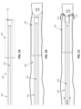
特に、本明細書には、可撓性チューブ(例えば、トラクタチューブまたは単にトラクタ)が回り込んで反転する反転支持カテーテルの端部に拡張可能なファネルを含むことができる装置が記載されている。可撓性チューブは、編まれた材料または織られた材料であってもよい。可撓性チューブは、一般に、プラー(細長いワイヤ、チューブ、カニューレなど)の遠位端領域に結合された第1の端部を有することができ、可撓性チューブは、ファネルのある反転支持カテーテルの遠位端で反転し、可撓性チューブの外側部分が反転支持カテーテル上で近位方向に延びるように構成されており、可撓性チューブの内側の(反転した)部分がファネル内に引き込まれる際に、可撓性チューブにより保持された(例えば、掴まれた)血栓を圧縮して血栓から流体を除去するものであり、血栓全体が捕捉され、圧縮され、外側カテーテル内に引き込まれるまで、反転支持カテーテル内に反転した可撓性チューブを引き込むようになっている。本明細書に記載の装置の構成は、遠位端に拡張可能なファネルを含む反転支持カテーテルを使用することにより、血栓、特に大径の血栓を掴んで除去するのに特に適している。折り畳み可能/拡張可能なファネルは、可撓性チューブが反転支持カテーテル内に反転して血栓を捕捉するように、反転支持カテーテル内に可撓性チューブを引っ張ることにより加えられる圧縮力で作動するように構成することができる。折り畳み可能/拡張可能なファネルは、可撓性チューブがファネルの遠位端面に横方向の圧縮力を加えたときに、完全に拡張されたロックされた(例えば、「詰まった」)形態をとるように構成することができる。さらに、ファネルは、血栓が反転支持カテーテルのより細い直径のルーメン内に移動して血栓を圧縮する際に、血栓から絞り出された流体がファネルから横方向に流出することができる開口部(本明細書では、多孔質構造を有すると記載されている)を含むことができる。例えば、血栓が圧縮されるときに流体がファネル壁から横方向に流出することを可能にする、折り畳み可能/拡張可能なファネル(本明細書では単に拡張可能なファネルと呼ぶことがある)を貫通する開口部は、血栓の目詰まりまたは詰りを防止することもできる。 In particular, devices are described herein that can include an expandable funnel at the end of an everting support catheter around which a flexible tube (eg, a tractor tube or simply a tractor) is wrapped around and everted. The flexible tube may be a braided or woven material. The flexible tube can generally have a first end coupled to the distal end region of a puller (elongated wire, tube, cannula, etc.), and the flexible tube can be attached to a funneled inversion support catheter. is inverted at its distal end, the outer portion of the flexible tube is configured to extend proximally over the inverted support catheter, and the inner (inverted) portion of the flexible tube is retracted into the funnel. the thrombus, which is held (e.g., grabbed) by the flexible tube, is compressed and fluid is removed from the thrombus until the entire thrombus is captured, compressed, and drawn into the outer catheter. , adapted to draw the everted flexible tube into the everted support catheter. The configuration of the device described herein is particularly suited for grasping and removing thrombi, particularly large diameter thrombi, by using an everting support catheter that includes an expandable funnel at its distal end. The collapsible/expandable funnel is actuated by compressive force applied by pulling the flexible tube into the everting support catheter such that the flexible tube inverts into the everting support catheter and captures the thrombus. It can be configured as follows. The collapsible/expandable funnel assumes a fully expanded locked (e.g., "stuck") configuration when the flexible tube applies a lateral compressive force to the distal end surface of the funnel. It can be configured as follows. In addition, the funnel has an opening (the main described in the specification as having a porous structure). For example, through a collapsible/expandable funnel (sometimes referred to herein simply as an expandable funnel) that allows fluid to exit laterally from the funnel wall when the thrombus is compressed. The opening may also prevent thrombus clogging or clogging.
一般に、本明細書に記載のこれら装置(例えば、システム)は何れも、細長い可撓性本体を有する反転支持カテーテルを含むことができ、この反転支持カテーテルは、細長い可撓性本体の遠位端に拡張可能なファネルを有し、例えば細長い可撓性本体に隣接する、拡張可能なファネルの近位端における拡張可能なファネルの少なくとも一部が、ファネル壁から横方向に血栓からの流体を通過させるための開口部を含む(例えば、ファネルは、多孔質であっても、部分的に多孔質であってもよい)。本装置は、可撓性チューブ(例えば、「トラクタ」)も含むことができる。トラクタは、織られたものまたは編まれたものであってもよい。いくつかの態様では、本装置が、反転支持カテーテルのルーメン内にプラーを含み、遠位端またはその近傍にあるプラーの第1の領域が、可撓性チューブに取り付けられる。可撓性チューブの第2の領域は、細長い可撓性本体の外面上に延在させることができる。システムは、可撓性チューブを反転支持カテーテル内に近位方向に引っ張ることにより(例えば、プラーを引っ張ることにより、または可撓性チューブの第1の端部を引っ張ることにより)、可撓性チューブが拡張可能なファネルの遠位端で反転する際に、ファネルは、ロックされた(詰まった)形態まで完全に拡張することができ、それにより、可撓性チューブが、拡張可能なファネルの開放された遠位端(例えば、遠位エッジ)で回り込んで(ローリングして)反転するように構成されている。可撓性チューブのこのローリング運動は、可撓性チューブの構造(例えば、織られた構造、編まれた構造など)と同様に、血栓を捕捉し、反転支持カテーテルのルーメン内に引き込み、ルーメン内に引き込む際に、血栓を圧縮して、血栓から流体を除去することができる。可撓性チューブの第1の領域は、可撓性チューブの端部領域であってもよい。可撓性チューブの第2の端部領域は、端部領域であってもよい。 Generally, any of these devices (e.g., systems) described herein can include an everting support catheter having an elongate flexible body, the everting support catheter having a distal end of the elongate flexible body. at least a portion of the expandable funnel at the proximal end of the expandable funnel, e.g., adjacent to the elongated flexible body, passes fluid from the thrombus laterally from the funnel wall. (eg, the funnel may be porous or partially porous). The device can also include a flexible tube (eg, a "tractor"). The tractor may be woven or knitted. In some embodiments, the device includes a puller within the lumen of the everting support catheter, and a first region of the puller at or near the distal end is attached to the flexible tube. A second region of flexible tubing can extend over the outer surface of the elongate flexible body. By pulling the flexible tube proximally into the inversion support catheter (e.g., by pulling a puller or by pulling a first end of the flexible tube), the system is inverted at the distal end of the expandable funnel, the funnel can be fully expanded to a locked (stuck) configuration, thereby allowing the flexible tube to open the expandable funnel. The distal end (e.g., the distal edge) is configured to roll and flip at the distal end (eg, distal edge). This rolling motion of the flexible tube, as well as the structure of the flexible tube (e.g., woven, braided, etc.), traps and draws the thrombus into the lumen of the everting support catheter, allowing it to flow through the lumen. The thrombus can be compressed and fluid removed from the thrombus during retraction. The first region of the flexible tube may be an end region of the flexible tube. The second end region of the flexible tube may be an end region.
これら装置の何れにおいても、反転支持カテーテルおよび可撓性チューブアセンブリを、除去する1または複数の血栓を含む血管系の領域に展開するのを助けるために、送達カテーテル(本明細書では中間カテーテルとも称する)を使用することができる。例えば、システムは、中間カテーテルと、中間カテーテル内の反転支持カテーテルであって、反転支持カテーテルが細長い可撓性本体を有し、反転支持カテーテルが細長い可撓性本体の遠位端に拡張可能なファネルを有し、拡張可能なファネルが、細長い可撓性本体に隣接する拡張可能なファネルの近位端に多孔質領域を有する、反転支持カテーテルと、反転支持カテーテルのルーメン内のプラーと、織られた可撓性チューブであって、反転支持カテーテル内でプラーに取り付けられた第1の領域と、細長い可撓性本体の外面上に延びる第2の領域とを有する可撓性チューブとを含むことができ、可撓性チューブは、拡張可能なファネルの遠位端で反転し、さらに、可撓性チューブは、プラーを近位方向に引っ張ることにより反転支持カテーテル内に近位方向に引き込まれ、反転支持カテーテル内に引き込まれる際に、第2の領域が拡張可能なファネルの遠位端で回り込んで反転するように構成されている。 In any of these devices, a delivery catheter (also referred to herein as an intermediate catheter) is used to assist in deploying the everting support catheter and flexible tube assembly to the area of the vasculature containing the thrombus or thrombus to be removed. ) can be used. For example, the system includes an intermediate catheter and an inversion support catheter within the intermediate catheter, the inversion support catheter having an elongated flexible body, and the inversion support catheter expandable at a distal end of the elongated flexible body. an everting support catheter having a funnel, the expandable funnel having a porous region at a proximal end of the expandable funnel adjacent the elongate flexible body; a puller within a lumen of the everting support catheter; a flexible tube having a first region attached to a puller within the inversion support catheter and a second region extending over an outer surface of the elongated flexible body. The flexible tube can be everted at the distal end of the expandable funnel, and the flexible tube can be pulled proximally into the everting support catheter by pulling the puller proximally. , the second region is configured to wrap around and evert at the distal end of the expandable funnel upon being drawn into the everting support catheter.
これらのシステムの何れかは、細長い可撓性本体の外径上に延びる可撓性チューブの第2の領域の内径を、拡張した形態の拡張可能なファネルの最大外径よりも大きくすることができる。これら請求項の何れかのシステムは、細長い可撓性本体の遠位端に隣接する拡張可能なファネルの基部領域が多孔質であってもよい。例えば、拡張可能なファネルは、細長い可撓性本体の遠位端に隣接する拡張可能なファネルの基部に周方向の多孔質領域を含むことができる。 Any of these systems may have an inner diameter of the second region of the flexible tube extending over the outer diameter of the elongate flexible body that is greater than the maximum outer diameter of the expandable funnel in the expanded configuration. can. The system of any of these claims may be such that the base region of the expandable funnel adjacent the distal end of the elongate flexible body is porous. For example, the expandable funnel can include a circumferential porous region at the base of the expandable funnel adjacent the distal end of the elongate flexible body.
これらのシステムの何れかにおいて、折り畳まれた形態は、細長い可撓性本体の外径の約0.3倍未満の最大外径、および/または約8mm未満の最大外径を有することができる。 In any of these systems, the folded configuration can have a maximum outer diameter that is less than about 0.3 times the outer diameter of the elongate flexible body, and/or a maximum outer diameter that is less than about 8 mm.
拡張した形態は、細長い可撓性本体の外径の約2倍よりも大きい最小外径を有することができる。例えば、拡張した形態は、約2mm~約26mmの外径を有することができる。 The expanded configuration can have a minimum outer diameter that is greater than about twice the outer diameter of the elongated flexible body. For example, the expanded configuration can have an outer diameter of about 2 mm to about 26 mm.
本明細書に記載のシステムの何れかにおいては、可撓性チューブが、編まれたチューブを含むことができる。いくつかの態様では、可撓性チューブを、織られた材料または材料のシート(例えば、レーザカットされたもの)で形成することができる。チューブは、ストランドまたはフィラメント(例えば、モノフィラメントまたはマルチフィラメント)から形成することができる。例えば、可撓性チューブは、編まれたチューブの長軸に沿って、編まれたチューブの横断面あたり10よりも多いループを有する編まれたチューブを含むことができる。 In any of the systems described herein, the flexible tube can include a braided tube. In some embodiments, the flexible tube can be formed from a woven material or a sheet of material (eg, laser cut). The tube can be formed from strands or filaments (eg, monofilament or multifilament). For example, the flexible tube can include a braided tube having more than 10 loops per cross-section of the braided tube along the long axis of the braided tube.
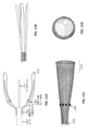
一般に、拡張可能なファネルは、シート状の材料、織られた材料、編組材料および/または編まれた材料で形成することができ、1または複数の支持体(アーム、ストラットなど)を含むことができる。例えば、拡張可能なファネルは、拡張可能なファネルの遠位端でそれ自体の上に反転するメッシュであってもよい。 Generally, expandable funnels can be formed of sheeted, woven, braided and/or knitted materials and can include one or more supports (arms, struts, etc.). can. For example, the expandable funnel may be a mesh that flips onto itself at the distal end of the expandable funnel.
いくつかの態様では、拡張可能なファネルが、細長い可撓性本体と連続する複数の長手方向のタインを含む。拡張可能なファネルは、自己拡張するものであってもよく(例えば、少なくとも部分的に開くようにバイアスがかかっており)、代替的または追加的には、拡張可能なファネルは、可撓性チューブの第1の領域が近位方向に引っ張られたときに拡張するように構成されるものであってもよい。いくつかの態様では、拡張可能なファネルは、自己拡張するように構成され、拘束されていない形態において、自己拡張した形態を達成するように構成されるものであってもよい。 In some aspects, the expandable funnel includes a plurality of longitudinal tines continuous with the elongated flexible body. The expandable funnel may be self-expanding (e.g., biased at least partially open); alternatively or additionally, the expandable funnel may be made of a flexible tube. The first region may be configured to expand when pulled in a proximal direction. In some aspects, the expandable funnel is configured to self-expand and may be configured to achieve a self-expanding configuration in an unconstrained configuration.
一般に、拡張可能なファネルは、反転支持カテーテルの残りの部分に一体化されており、それらが部分を形成する。このため、拡張可能なファネルの内部は、典型的には、カテーテルの残りの部分のルーメンと流体的に連通しており、カテーテルのルーメンは、ファネルの内部を含むことができる。同様に、カテーテル本体の外面は、文脈が別段の指定をしない限り、拡張可能なファネルの外面を含み、かつ包含する。 Generally, the expandable funnel is integrated with and forms part of the remaining portions of the inversion support catheter. As such, the interior of the expandable funnel is typically in fluid communication with the lumen of the remainder of the catheter, and the lumen of the catheter may include the interior of the funnel. Similarly, the outer surface of the catheter body includes and encompasses the outer surface of the expandable funnel, unless the context dictates otherwise.
これらの装置の何れかは、拡張可能なファネルの少なくとも一部を覆う潤滑性スリーブを含むことができる。例えば、潤滑性スリーブは、拡張可能なファネルの内部の遠位端領域を覆うことができる。いくつかの態様では、潤滑性スリーブが、ファネルの遠位端の上に延びる。いくつかの態様では、潤滑性スリーブが1または複数の開口部を含み、それら開口部が、近位部分(例えば、拡張可能なファネルの基部の近く)にある。 Any of these devices can include a lubricious sleeve covering at least a portion of the expandable funnel. For example, a lubricious sleeve can cover the interior distal end region of the expandable funnel. In some embodiments, a lubricious sleeve extends over the distal end of the funnel. In some embodiments, the lubricious sleeve includes one or more openings in a proximal portion (eg, near the base of the expandable funnel).
一般に、拡張可能なファネルは、拡張した形態において、任意の適切なサイズであってもよく、例えば、2~26mmの最大外径を有する。例えば、拡張した形態では、16mmよりも大きい(例えば、約2mm、3mm、4mm、5mm、6mm、7mm、8mm、9mm、10mm、12mm、14mm、16mm、18mm、20mmなどよりも大きい)最大外径を有することができる。ユーザは、一般に、デバイスが使用される血管の内径(例えば、代替的または追加的には、除去される血栓の外径)の約60%(例えば、約70%、約75%、約80%、約85%、約90%、約95%など)またはそれ以上の範囲内にある最大サイズを有する反転支持カテーテルを選択することができる。 Generally, the expandable funnel may be of any suitable size in the expanded configuration, for example having a maximum outer diameter of 2 to 26 mm. For example, in the expanded configuration, a maximum outer diameter greater than 16mm (e.g., greater than about 2mm, 3mm, 4mm, 5mm, 6mm, 7mm, 8mm, 9mm, 10mm, 12mm, 14mm, 16mm, 18mm, 20mm, etc.) can have. Users generally select a diameter that is about 60% (e.g., about 70%, about 75%, about 80%) of the inner diameter of the blood vessel in which the device is used (e.g., alternatively or additionally, the outer diameter of the blood clot being removed). , about 85%, about 90%, about 95%, etc.) or more.
本明細書に記載の装置(例えば、システム)の何れかは、少なくとも部分的に反転支持カテーテルを取り囲む中間カテーテル、および/または反転支持カテーテルのルーメン内のプラーを含むことができる。例えば、可撓性チューブの第2の端部は、プラーの遠位端領域に結合される。第1の領域は、プラーの遠位端領域よりも近位側に結合される。 Any of the devices (eg, systems) described herein can include an intermediate catheter that at least partially surrounds the everting support catheter, and/or a puller within a lumen of the everting support catheter. For example, the second end of the flexible tube is coupled to the distal end region of the puller. The first region is coupled more proximally than the distal end region of the puller.
一般に、本明細書に記載の拡張可能なファネルは、可撓性チューブを反転させて回り込ませ、ファネル内に血栓を(非常に大きな直径の血栓であっても)引き込み、血栓を圧縮し(例えば、血栓の流体の多くを除去し)、圧縮した血栓を反転支持カテーテル本体内に引き込むのに十分な引張力に耐えるように構成することができる。例えば、拡張可能なファネルは、圧縮力が軸方向(例えば、近位方向)に向けられたときに潰れることなく、約500gより大きい(例えば、約600gより大きい、約700gより大きい、約750gより大きい、約800gより大きい、約900gより大きい、約1000gより大きい、約1100gより大きい、約1200gより大きい、約1300gより大きい、約1400gより大きい、約1500g等より大きい)圧縮力に耐えるように構成することができる。例えば、拡張可能なファネルは、1200gを超える圧縮力にも潰れることなく耐えるように構成することができる。いくつかの態様では、圧縮力によって、ファネルが織られた材料、編まれた材料または編組材料で作られている場合には特に、ファネルを一緒にロックするか、または積み重ねることができる。例えば、織られたファネルの場合、圧縮力がファネル材料の織り目を軸方向に詰まらせ、遠位(より広い)領域の編組角度を増加させ、ファネルのカラム強度を増加させることができる。 In general, the expandable funnels described herein are constructed by inverting and wrapping a flexible tube to draw a thrombus (even a very large diameter thrombus) into the funnel and compress the thrombus (e.g. , removing much of the fluid in the thrombus) and can be configured to withstand tensile forces sufficient to pull the compressed thrombus into the everting support catheter body. For example, an expandable funnel may be larger than about 500 g (e.g., greater than about 600 g, greater than about 700 g, greater than about 750 g) without collapsing when a compressive force is directed in an axial direction (e.g., proximally). large, greater than about 800 g, greater than about 900 g, greater than about 1000 g, greater than about 1100 g, greater than about 1200 g, greater than about 1300 g, greater than about 1400 g, greater than about 1500 g, etc.) configured to withstand compressive forces. can do. For example, the expandable funnel can be configured to withstand compressive forces in excess of 1200 g without collapsing. In some embodiments, compressive forces can lock or stack the funnels together, especially when the funnels are made of woven, knitted, or braided materials. For example, in the case of a woven funnel, compressive forces can axially close the weave of the funnel material, increasing the braid angle in the distal (wider) region and increasing the column strength of the funnel.
例えば、血栓除去システムは、細長い可撓性のカテーテル本体と、カテーテルルーメンと、カテーテル本体の遠位端に配置された拡張可能なファネルとを有する反転支持カテーテルであって、ファネルの遠位端が、ファネルの内部およびカテーテルルーメンとそれぞれ連通する遠位開口部を規定する、反転支持カテーテルと、ファネルの内部に少なくとも部分的に配置される第1の領域と、ファネルの外部に少なくとも部分的に延在する第2の領域とを有するように、ファネルの遠位端で反転する可撓性チューブとを備えることができ、可撓性チューブが、第1の領域を近位方向に引っ張ることにより、カテーテルルーメン内に近位方向に引き込まれるように構成され、可撓性チューブがカテーテルルーメン内に引き込まれる際に、第2の領域がファネルの遠位端で回り込むようになっている。 For example, a thrombectomy system includes an inverted support catheter having an elongated flexible catheter body, a catheter lumen, and an expandable funnel disposed at a distal end of the catheter body, the distal end of the funnel being an inverted support catheter defining a distal opening in communication with the interior of the funnel and the catheter lumen, respectively; a first region disposed at least partially within the funnel; and a first region extending at least partially outside the funnel. a flexible tube that is everted at the distal end of the funnel so as to have a second region located therein, the flexible tube pulling the first region in a proximal direction so as to The second region is configured to be drawn proximally into the catheter lumen such that the second region wraps around the distal end of the funnel as the flexible tube is drawn into the catheter lumen.
いくつかの態様では、血栓除去システムは、細長い可撓性のカテーテル本体と、カテーテルルーメンと、カテーテル本体の遠位端に配置された拡張可能なファネルとを有する反転支持カテーテルであって、ファネルの遠位端が、ファネルの内部およびカテーテルルーメンとそれぞれ連通する遠位開口部を規定し、カテーテル本体に隣接するファネルの少なくとも近位部分が、流体を通過させるように構成された開口部を含む、反転支持カテーテルと、カテーテルルーメン内に配置されたプラーと、編まれた材料または織られた材料で形成された可撓性チューブであって、ファネルの遠位端で反転し、かつプラーに連結された第1の領域と、ファネルの外面上に少なくとも部分的に延在する第2の領域とを有する可撓性チューブとを備えることができ、可撓性チューブは、プラーを近位方向に引っ張ることによって、カテーテルルーメン内に近位方向に引き込まれ、それにより可撓性チューブの第2の領域がファネルの内部を通過してカテーテルルーメン内に入るように構成されている。 In some embodiments, the thrombectomy system is an inverted support catheter having an elongated flexible catheter body, a catheter lumen, and an expandable funnel disposed at a distal end of the catheter body, the funnel the distal end defines a distal opening in communication with the interior of the funnel and the catheter lumen, respectively, and at least a proximal portion of the funnel adjacent the catheter body includes an opening configured to pass fluid therethrough; an inverted support catheter, a puller disposed within the catheter lumen, and a flexible tube formed of a braided or woven material that is inverted at a distal end of the funnel and connected to the puller. and a second region extending at least partially over the outer surface of the funnel, the flexible tube pulling the puller in a proximal direction. The second region of flexible tubing is configured to be drawn proximally into the catheter lumen such that the second region of the flexible tube passes through the interior of the funnel and into the catheter lumen.
血栓除去システムは、細長い可撓性のカテーテル本体と、カテーテルルーメンと、カテーテル本体の遠位端に配置された拡張可能なファネルとを有する反転支持カテーテルであって、ファネルの遠位端が、ファネルの内部およびカテーテルルーメンとそれぞれ連通する遠位開口部を規定し、カテーテル本体に隣接するファネルの少なくとも近位部分が、流体を通過させるように構成された開口部を含む、反転支持カテーテルと、編まれた可撓性チューブであって、ファネルの遠位端で反転し、かつファネルの内部に少なくとも部分的に配置される第1の領域と、ファネルの外面上に少なくとも部分的に延在する第2の領域とを有する可撓性チューブとを備えることができ、可撓性チューブが、可撓性チューブの第1の領域を近位方向に引っ張ることにより、カテーテルルーメン内に近位方向に引き込まれるように構成され、可撓性チューブがファネルの内部およびカテーテルルーメン内にそれぞれ引き込まれる際に、可撓性チューブの第2の領域がファネルの遠位端で回り込むようになっており、ファネルは、可撓性チューブの第1の領域を近位方向に引っ張ることによって、ファネルを拡張して詰まった形態に拡張させる軸方向の荷重をファネルに加えるように構成されている。 The thrombectomy system is an inverted support catheter having an elongated flexible catheter body, a catheter lumen, and an expandable funnel disposed at a distal end of the catheter body, the distal end of the funnel an inverted support catheter, wherein at least a proximal portion of the funnel adjacent the catheter body includes an opening configured to pass fluid therethrough; a first region inverted at the distal end of the funnel and disposed at least partially within the funnel; and a first region extending at least partially over an exterior surface of the funnel. a flexible tube having a second region, the flexible tube being pulled proximally into the catheter lumen by pulling the first region of the flexible tube proximally. the second region of the flexible tube wraps around the distal end of the funnel as the flexible tube is drawn into the funnel and into the catheter lumen, respectively; , is configured to apply an axial load to the funnel causing the funnel to expand into a plugged configuration by pulling the first region of the flexible tube in a proximal direction.
また、本明細書には、本明細書に記載の装置の何れかを使用して血管から血栓を除去する方法も記載されている。例えば、血管から血栓を除去する方法は、反転チューブ装置の遠位端が血栓に近接するまで、反転チューブ装置を血管を通して前進させるステップであって、反転チューブ装置は、細長い可撓性本体の遠位端に配置された拡張可能なファネルを有する反転支持カテーテルと、反転支持カテーテル内の第1の領域および反転支持カテーテルの外面上に延在する第2の領域を有する可撓性チューブとを備える、ステップと、血管内で、拡張可能なファネルを折り畳まれた形態から拡張した形態に拡張させるステップと、可撓性チューブの第1の領域を近位方向に引っ張って、反転支持カテーテルの拡張可能なファネルの遠位端で可撓性チューブを回し込み、それにより可撓性チューブが拡張可能なファネルの遠位端で反転して、血栓を捕捉し、血栓を反転支持カテーテル内に近位方向に引き込むステップとを備えることができ、血栓を反転支持カテーテル内に近位方向に引き込むことは、血栓を圧縮して、血栓から流体を反転支持カテーテルの外に横方向に排出することを含む。 Also described herein is a method of removing a blood clot from a blood vessel using any of the devices described herein. For example, a method of removing a thrombus from a blood vessel may include advancing an everting tube device through the blood vessel until a distal end of the everting tube device is proximate the thrombus, the everting tube device disposed at a distal end of an elongate flexible body. an everting support catheter having an expandable funnel disposed distally; and a flexible tube having a first region within the everting support catheter and a second region extending over an outer surface of the everting support catheter. , expanding the expandable funnel from a collapsed configuration to an expanded configuration within the blood vessel; and pulling the first region of the flexible tube in a proximal direction to expand the inversion support catheter. the flexible tube at the distal end of the expandable funnel, thereby inverting the flexible tube at the distal end of the expandable funnel to capture the thrombus and invert the thrombus proximally into the support catheter. and drawing the thrombus proximally into the everting support catheter includes compressing the thrombus and expelling fluid from the thrombus laterally out of the everting support catheter.
例えば、血管から血栓を除去する方法は、反転チューブ装置の遠位端部が血栓に近接して位置するまで、反転チューブ装置を血管を通して前進させるステップであって、反転チューブ装置は、細長い可撓性のカテーテル本体と、内部のカテーテルルーメンと、カテーテル本体の遠位端に配置された拡張可能なファネルとを有する反転支持カテーテルであって、ファネルの遠位端が、ファネルの内部およびカテーテルルーメンとそれぞれ連通する開口部を規定する、反転支持カテーテルを備え、反転チューブ装置は、拡張可能なファネルの遠位端で反転し、かつファネルの内部に少なくとも部分的に配置される第1の領域と、ファネルの外面上に少なくとも部分的に延在する第2の領域とを有する可撓性チューブをさらに備える、ステップと、血栓に近接する血管内で、ファネルを折り畳まれた送達形態から拡張した形態へと拡張させるステップと、可撓性チューブの第1の領域を近位方向に引っ張って、ファネルの遠位端で可撓性チューブの第2の領域を回し込み、それにより可撓性チューブが血栓を捕捉し、血栓をファネルの内部およびカテーテルルーメン内に近位方向に引き込むステップとを備えることができる。 For example, a method of removing a thrombus from a blood vessel includes advancing an everting tube device through the blood vessel until a distal end of the everting tube device is positioned proximate the thrombus, the everting tube device comprising an elongated flexible an inverted support catheter having a flexible catheter body, an interior catheter lumen, and an expandable funnel disposed at a distal end of the catheter body, the distal end of the funnel being in contact with the interior of the funnel and the catheter lumen; an everting support catheter each defining a communicating opening, the everting tube device everting at a distal end of the expandable funnel and a first region disposed at least partially within the funnel; and a second region extending at least partially over an exterior surface of the funnel; converting the funnel from a collapsed delivery configuration to an expanded configuration within the blood vessel proximate the thrombus. and expanding the flexible tube by pulling the first region of the flexible tube proximally and passing the second region of the flexible tube at the distal end of the funnel, thereby causing the flexible tube to dislodge the thrombus. and drawing the thrombus proximally into the funnel and into the catheter lumen.
本明細書に記載の血管から血栓を除去する方法の何れかは、それら装置の何れかを使用することを含むことができる。例えば、血管から血栓を除去する方法は、反転チューブ装置の遠位端が血栓に近接するまで、反転チューブ装置を血管を通して前進させるステップであって、反転チューブ装置は、細長い可撓性本体の遠位端に配置された拡張可能なファネルを有する反転支持カテーテルと、反転支持カテーテル内の第1の領域および反転支持カテーテルの外面上に延在する第2の領域を有する可撓性チューブとを備える、ステップと、血管内で、拡張可能なファネルを折り畳まれた送達形態から拡張形態へと拡張させるステップと、可撓性チューブの第1の領域を近位方向に引っ張って、反転支持カテーテルの拡張可能なファネルの遠位端で可撓性チューブをローリングさせ、それにより可撓性チューブが拡張可能なファネルの遠位端で反転して、血栓を捕捉し、血栓を反転支持カテーテル内に近位方向に引き込むステップとを備えることができ、血栓を反転支持カテーテル内に近位方向に引き込むことは、血栓を圧縮して、血栓から流体を反転支持カテーテルの外に横方向に排出することを含む。 Any of the methods of removing a blood clot from a blood vessel described herein can include using any of these devices. For example, a method of removing a thrombus from a blood vessel may include advancing an everting tube device through the blood vessel until a distal end of the everting tube device is proximate the thrombus, the everting tube device disposed at a distal end of an elongate flexible body. an everting support catheter having an expandable funnel disposed distally; and a flexible tube having a first region within the everting support catheter and a second region extending over an outer surface of the everting support catheter. , expanding the expandable funnel from the collapsed delivery configuration to the expanded configuration within the blood vessel; and pulling the first region of the flexible tube in a proximal direction to expand the everting support catheter. rolling the flexible tube at the distal end of the expandable funnel such that the flexible tube is everted at the distal end of the expandable funnel to capture the thrombus and invert the thrombus proximally into the support catheter. and drawing the thrombus proximally into the everting support catheter includes compressing the thrombus and expelling fluid from the thrombus laterally out of the everting support catheter. .
これらの方法の何れかは、上述したように、血管のサイズに基づいて反転チューブ装置のサイズを選択するステップを含むことができる。したがって、ユーザは、血管および/または血栓のサイズに基づいて、中間カテーテルおよび/または可撓性チューブの様々な異なるサイズのなかから選択することができる。 Any of these methods can include selecting the size of the everting tube device based on the size of the blood vessel, as described above. Accordingly, a user can choose between a variety of different sizes of intermediate catheters and/or flexible tubes based on the size of the blood vessel and/or thrombus.
これらの方法の何れかにおいて、拡張させることは、拡張可能なファネルを、血栓の外径の少なくとも1/3よりも大きい外径(例えば、血栓のODおよび/または血管のIDの33%よりも大きい、40%よりも大きい、50%よりも大きい、60%よりも大きい、70%よりも大きい、80%よりも大きい、90%よりも大きい外径など)に拡張させることを含むことができる。例えば、拡張させることは、拡張可能なファネルを、血栓の外径の少なくとも50%よりも大きい外径に拡張させることを含むことができる。 In any of these methods, expanding the expandable funnel includes an outer diameter that is greater than at least 1/3 of the outer diameter of the thrombus (e.g., greater than 33% of the OD of the thrombus and/or the ID of the vessel). larger, greater than 40%, greater than 50%, greater than 60%, greater than 70%, greater than 80%, greater than 90%, etc.) . For example, expanding can include expanding the expandable funnel to an outer diameter that is greater than at least 50% of the outer diameter of the thrombus.
いくつかの態様は、血栓を近位方向に引っ張ることは、500g~3000gの力を加えることを含むことができる。 In some embodiments, pulling the thrombus proximally can include applying a force of 500 g to 3000 g.
いくつかの態様では、拡張可能なファネルを拡張させることは、拡張可能なファネルを血管内で自己拡張可能とすることを含み、かつ/または拡張可能なファネルを拡張させることは、可撓性チューブの第1の領域を近位方向に引っ張ることによって、拡張可能なファネルに軸方向の圧縮力を加えることを含むことができる。自己拡張可能なファネルは、可撓性チューブを近位方向に引っ張って拡張可能なファネルに軸方向の圧縮力を加えることにより、さらに拡張させることができる。例えば、いくつかの態様では、拡張可能なファネルが、拘束されていないとき、例えば第2のカテーテル(例えば、ガイドカテーテル、中間カテーテルなどの)内の拘束された形態から解放されたときに、自己拡張した形態に自己拡張するように構成されるものであってもよい。 In some embodiments, expanding the expandable funnel includes making the expandable funnel self-expandable within the blood vessel, and/or expanding the expandable funnel includes making the expandable funnel self-expandable within the blood vessel. may include applying an axial compressive force to the expandable funnel by pulling the first region of the expandable funnel in a proximal direction. The self-expandable funnel can be further expanded by pulling the flexible tube proximally to apply an axial compressive force to the expandable funnel. For example, in some embodiments, the expandable funnel self-grows when unconstrained, e.g., when released from a constrained configuration within a second catheter (e.g., guide catheter, intermediate catheter, etc.). It may be configured to self-expand into an expanded form.
これらの方法の何れかは、可撓性チューブを反転支持カテーテル内から除去するステップと、新しい可撓性チューブを反転支持カテーテル内に再装填するステップとを含むことができる。 Any of these methods can include the steps of removing the flexible tube from within the everting support catheter and reloading a new flexible tube within the everting support catheter.
例えば、本明細書に記載のシステムは、血栓除去システムを含む。これらのシステムの何れかは、細長い可撓性本体を有する反転支持カテーテルであって、細長い可撓性本体の遠位端に拡張可能なファネルを有する反転支持カテーテルと、反転支持カテーテル内の第1の領域および細長い可撓性本体の外面上に延在する第2の領域を有する可撓性チューブとを含むことができ、可撓性チューブが拡張可能なファネルの遠位端で反転し、さらに、可撓性チューブが、第1の領域を近位方向に引っ張ることによって、反転支持カテーテル内に近位方向に引き込まれ、反転支持カテーテル内に引き込まれる際に、第2の領域が拡張可能なファネルの遠位端で回り込んで反転するように構成されている。 For example, the systems described herein include thrombectomy systems. Any of these systems includes an inversion support catheter having an elongate flexible body, the inversion support catheter having an expandable funnel at a distal end of the elongate flexible body; a flexible tube having a region of , the flexible tube is drawn proximally into the everting support catheter by pulling the first region proximally, and the second region is expandable as the flexible tube is drawn into the everting support catheter. It is configured to wrap around and invert at the distal end of the funnel.
これらのシステムの何れかは、細長い可撓性本体を有するとともに、この細長い可撓性本体の遠位端に拡張可能なファネルを有する反転支持カテーテルであって、細長い可撓性本体に隣接する拡張可能なファネルの少なくとも近位端が、流体を通過させるように構成された開口部を含む、反転支持カテーテルと、反転支持カテーテルのルーメン内に配置されたプラーと、編まれた材料または織られた材料で形成された可撓性チューブであって、反転支持カテーテル内でプラーに連結された第1の領域と、細長い可撓性本体の外面上に延在する第2の領域とを有する可撓性チューブとを含むことができ、可撓性チューブが拡張可能なファネルの遠位端で反転し、さらに、可撓性チューブが、プラーを近位方向に引っ張ることによって、反転支持カテーテル内に近位方向に引き込まれ、反転支持カテーテル内に引き込まれる際に、可撓性チューブが拡張可能なファネルの遠位端で回り込んで反転するように構成されている。 Any of these systems includes an inversion support catheter having an elongated flexible body and an expandable funnel at a distal end of the elongated flexible body, the expansion support catheter having an expandable funnel adjacent to the elongated flexible body. an everting support catheter, at least a proximal end of the possible funnel including an opening configured to allow fluid to pass therethrough; a puller disposed within the lumen of the everting support catheter; and a braided or woven material. a flexible tube formed of a material having a first region connected to a puller within the inversion support catheter and a second region extending over an outer surface of the elongated flexible body; a flexible tube, the flexible tube being everted at the distal end of the expandable funnel, and the flexible tube being proximally inserted into the everting support catheter by pulling the puller proximally. The flexible tube is configured to wrap around and evert at the distal end of the expandable funnel as it is pulled into the inversion support catheter.
例えば、システムは、細長い可撓性本体を有するとともに、この細長い可撓性本体の遠位端に拡張可能なファネルを有する反転支持カテーテルであって、細長い可撓性本体に隣接する拡張可能なファネルの少なくとも近位端が、流体を通過させるように構成された開口部を含む、反転支持カテーテルと、反転支持カテーテルのルーメン内にあるプラーと、編まれた可撓性チューブであって、反転支持カテーテル内でプラーに連結された第1の領域と、細長い可撓性本体の外面上に延在する第2の領域とを有する可撓性チューブとを含むことができ、可撓性チューブが拡張可能なファネルの遠位端で反転し、さらに、可撓性チューブが、プラーを近位方向に引っ張ることによって、反転支持カテーテル内に近位方向に引き込まれ、反転支持カテーテル内に引き込まれる際に、可撓性チューブが拡張可能なファネルの遠位端で回り込んで反転し、それによりファネルに軸方向の荷重を加えてファネルを拡張形態に拡張させるように構成されている。 For example, the system includes an inversion support catheter having an elongated flexible body and an expandable funnel at a distal end of the elongated flexible body, the expandable funnel adjacent the elongated flexible body. an inversion support catheter, at least a proximal end of which includes an opening configured to allow fluid to pass therethrough; a puller within a lumen of the inversion support catheter; and a braided flexible tube comprising: an inversion support catheter; and a flexible tube having a first region coupled to a puller within the catheter and a second region extending on an outer surface of the elongate flexible body, the flexible tube being expanded. The flexible tube is then pulled proximally into the everting support catheter by pulling the puller proximally, and as the flexible tube is pulled into the everting support catheter. , the flexible tube is configured to wrap around and invert at the distal end of the expandable funnel, thereby applying an axial load to the funnel to expand the funnel to an expanded configuration.
これらのシステムの何れかにおいて、細長い可撓性本体の外径上に延びる可撓性チューブの第2の領域の内径は、拡張形態における拡張可能なファネルの最大外径よりも小さくてもよい。このため、可撓性チューブは、反転支持カテーテルのより近位側の本体上のより細い弛緩した直径から反転支持カテーテルのファネル部分の上に引っ張られるときに、拡張されるようにしてもよい。本明細書に記載の装置の何れかにおいて、可撓性チューブは、反転部分(反転支持カテーテル内にあるとき)が自己拡張するように(または拡張するように形状設定されるように)、例えば、反転支持カテーテルの細長い本体の内径よりも40%以上大きい(例えば、50%以上、60%以上、70%以上、75%以上、または80%以上大きい)外径を有するように、バイアスがかけられるものであってもよい。 In any of these systems, the inner diameter of the second region of the flexible tube that extends over the outer diameter of the elongate flexible body may be less than the maximum outer diameter of the expandable funnel in the expanded configuration. To this end, the flexible tube may be expanded when pulled from a narrower relaxed diameter on the more proximal body of the inversion support catheter over the funnel portion of the inversion support catheter. In any of the devices described herein, the flexible tube is configured such that the everting portion (when within the everting support catheter) is self-expanding (or configured to expand), e.g. , biased to have an outer diameter that is 40% or more (e.g., 50% or more, 60% or more, 70% or more, 75% or more, or 80% or more) larger than the inner diameter of the elongated body of the inversion support catheter. It may be something that can be done.
上述したように、細長い可撓性本体の遠位端に隣接する拡張可能なファネルの基部領域は、流体を通過させるように構成された開口部を含むことができる(例えば、多孔質と称する場合もある)。いくつかの態様では、開口部または孔が、織られたファネル本体を形成する1または複数のストランド間の開口部によって形成されるものであってもよい。例えば、拡張可能なファネルは、細長い可撓性本体の遠位端に隣接する拡張可能なファネルの基部に周方向の多孔質領域を含むことができる。 As mentioned above, the base region of the expandable funnel adjacent the distal end of the elongate flexible body can include an opening configured to pass fluid (e.g., when referred to as porous). ). In some embodiments, the openings or holes may be formed by openings between one or more strands forming the woven funnel body. For example, the expandable funnel can include a circumferential porous region at the base of the expandable funnel adjacent the distal end of the elongated flexible body.
拡張可能なファネルの折り畳まれた形態は、細長い可撓性本体の外径の0.3倍(例えば、30%)未満の最大外径を有することができる。いくつかの型では、折り畳まれた形態は、拡張可能なファネルの遠位端を、反転支持カテーテルの細長い可撓性本体の外径(例えば、平均外径、またはファネルよりも近位側の反転支持カテーテルの領域)の30%以下、40%以下、50%以下、60%以下、70%以下、75%以下、80%以下等に折り畳むように構成されるものであってもよい。いくつかの態様では、折り畳まれた形態は、8mm未満の最大外径を有する。 The collapsed configuration of the expandable funnel can have a maximum outer diameter that is less than 0.3 times (eg, 30%) the outer diameter of the elongated flexible body. In some versions, the collapsed configuration connects the distal end of the expandable funnel to the outer diameter of the elongated flexible body of the inversion support catheter (e.g., the average outer diameter, or the inversion proximal to the funnel). It may be configured to fold up to 30% or less, 40% or less, 50% or less, 60% or less, 70% or less, 75% or less, 80% or less of the area of the support catheter. In some aspects, the folded configuration has a maximum outer diameter of less than 8 mm.
いくつかの態様では、拡張した形態が、細長い可撓性本体の外径の2倍を超える(例えば、2.5倍を超える、3倍を超える、3.5倍を超えるなど)最小外径を有することができる。最大外径は、通常はファネルの遠位面の直径であり、この遠位面は、遠位開口部または遠位エッジと呼ぶ場合もある。例えば、拡張した形態は、2~26mmの外径を有することができる。 In some aspects, the expanded configuration has a minimum outer diameter that is more than twice (e.g., more than 2.5 times, more than 3 times, more than 3.5 times, etc.) the outer diameter of the elongate flexible body. can have. The maximum outer diameter is typically the diameter of the distal face of the funnel, sometimes referred to as the distal opening or edge. For example, the expanded configuration can have an outer diameter of 2 to 26 mm.
上述したように、一般に、可撓性チューブは、編まれたチューブを含むことができ、例えば、可撓性チューブは、編まれたチューブの長軸に沿って、編まれたチューブの横断面あたり10を超えるループを有する編まれたチューブとして構成するようにしてもよい。 As mentioned above, in general, a flexible tube can include a braided tube, e.g., a flexible tube can be formed along the long axis of the braided tube, per cross-section of the braided tube. It may be configured as a braided tube with more than 10 loops.
後でさらに詳細に述べるように、拡張可能なファネルは、細長い可撓性本体と連続する複数の長手方向のタイン(例えば、ストラット)を含むことができる。それらのタインは、遠位方向(例えば、長手方向)に延びることができ、例えば、ファネルの口内の内側表面およびファネルの外側の外側表面を形成するためにそれ自体の上に折り畳まれたメッシュ材料(例えば、いくつかの態様では、織られた材料または編まれた材料)によって覆われるようにしてもよい。タインは、内側表面と外側表面との間に挿入することができ、内側表面と外側表面に対して長手方向に相対的に移動することができる。例えば、拡張可能なファネルは、拡張可能なファネルの遠位端でそれ自体の上に反転したメッシュを含むことができる。 As discussed in further detail below, the expandable funnel can include a plurality of longitudinal tines (eg, struts) that are continuous with the elongated flexible body. The tines may extend in a distal direction (e.g., longitudinally), e.g., a mesh material folded over itself to form the intraoral inner surface of the funnel and the outer outer surface of the funnel. (eg, in some embodiments, a woven or knitted material). The tines can be inserted between the inner and outer surfaces and can be moved longitudinally relative to the inner and outer surfaces. For example, the expandable funnel can include a mesh that is inverted onto itself at the distal end of the expandable funnel.
一般に、拡張可能なファネルは、少なくとも部分的に自己拡張するようにバイアスがかけられるようにしてもよい。いくつかの態様では、拡張可能なファネルが、可撓性チューブの第1の領域が近位方向に引っ張られたときに完全に拡張するように構成されている。 Generally, an expandable funnel may be biased to at least partially self-expand. In some aspects, the expandable funnel is configured to fully expand when the first region of the flexible tube is pulled proximally.
本明細書に記載の装置の何れかにおいて、潤滑性スリーブは、拡張可能なファネルの少なくとも一部を覆うことができ、例えば、内側表面および/または外側表面を覆い、かつ/または反転する遠位端領域を覆うことができる。 In any of the devices described herein, the lubricious sleeve can cover at least a portion of the expandable funnel, e.g., cover the inner surface and/or the outer surface, and/or cover the everted distal The edge area can be covered.
ファネルは、任意の適切な直径に開くように構成することができる。例えば、いくつかの態様では、拡張可能なファネルは、16mmを超える最大外径を有することができる。 The funnel can be configured to open to any suitable diameter. For example, in some aspects, the expandable funnel can have a maximum outer diameter greater than 16 mm.
本明細書に記載の装置の何れかは、反転支持カテーテルのルーメン内にプラー(ロッド、カテーテル、ワイヤなど)を含むことができ、可撓性チューブの第2の端部はプラーの遠位端領域に結合され、いくつかの態様では、可撓性チューブの第1の領域が、プラーの遠位端よりも近位側に取り付けられる。 Any of the devices described herein can include a puller (rod, catheter, wire, etc.) within the lumen of the inversion support catheter, with the second end of the flexible tube at the distal end of the puller. In some embodiments, a first region of the flexible tube is attached proximal to the distal end of the puller.
いくつかの態様では、血栓除去装置は、可撓性の細長い本体の遠位端に拡張可能なファネルを有する反転支持カテーテルを含むことができ、拡張可能なファネルは、それ自体の上に反転して内側ファネル表面および外側ファネル表面を形成する編まれた材料または織られた材料からなる第1のチューブにより形成されるファネル表面と、内側ファネル表面と外側ファネル表面との間で遠位方向に延在する複数の支持タインであって、ファネル表面が、複数の支持タインに対して軸方向に相対的にスライドするように構成されている、複数の支持タインと、カテーテル本体の外面に沿って遠位方向に延び、拡張可能なファネルでファネルの内部および反転支持カテーテルのルーメン内へと反転する編まれた材料または織られた材料からなる第2の可撓性チューブとを含み、拡張可能なファネルは、第2の可撓性チューブが反転支持カテーテル内に近位方向に引き込まれるときに、詰まった形態に拡張するように構成されている。上述したように、ファネル表面は、織られた材料を含むことができる。ある態様では、ファネル表面が、詰まった形態において、90度を超える編組角度を有する。 In some embodiments, a thrombectomy device can include an inverted support catheter having an expandable funnel at a distal end of a flexible elongate body, the expandable funnel inverted onto itself. a funnel surface formed by a first tube of braided or woven material forming an inner funnel surface and an outer funnel surface; and a funnel surface extending distally between the inner funnel surface and the outer funnel surface. a plurality of support tines, the plurality of support tines being configured to slide axially relative to the plurality of support tines, the funnel surface being configured to slide relative to the plurality of support tines; a second flexible tube of braided or woven material extending in the expandable funnel and everting at the expandable funnel into the interior of the funnel and into the lumen of the inversion support catheter; is configured to expand into a plugged configuration when the second flexible tube is drawn proximally into the everting support catheter. As mentioned above, the funnel surface can include a woven material. In some embodiments, the funnel surface has a braid angle of greater than 90 degrees in the packed configuration.
すなわち、本明細書に記載の拡張可能なファネルのいくつかの態様において、拡張可能なファネルは、例えばトラクタ(例えば、可撓性チューブ)を近位方向に引っ張ってトラクタがファネル上で反転支持カテーテルの外側から反転支持カテーテルのルーメン内に回り込んで反転することにより、軸方向に圧縮力が加えられたときに、詰まった形態をとるように構成することができる。詰まった形態は、拡張可能なファネルが詰まっていない形態よりも剛性の高い圧縮された形態をもたらすことができる。また、詰まった形態は、より大きなカラム強度も有する。拡張可能なファネルの壁が織られた材料から形成されている態様では、詰まった形態は、詰まった角度とも呼ばれる最大編組角度を有する織り目によってもたらされる。 That is, in some embodiments of the expandable funnels described herein, the expandable funnel can, for example, pull a tractor (e.g., a flexible tube) in a proximal direction so that the tractor inverts the supported catheter over the funnel. By wrapping around the lumen of the inversion support catheter from the outside and inverting it, it can be configured to assume a clogged configuration when compressive force is applied in the axial direction. The packed configuration can provide a compressed configuration in which the expandable funnel is more rigid than the unfilled configuration. The packed morphology also has greater column strength. In embodiments where the walls of the expandable funnel are formed from a woven material, the packed configuration is provided by the weave having a maximum braid angle, also referred to as the packed angle.
上述したように、複数のタインは、可撓性の細長い本体から形成(例えば、レーザカットなどのように切断)されるものであってもよい。また、拡張可能なファネルは、ファネル表面の周りに放射状に延び、拡張可能なファネルの外径を拘束する1または複数の周方向支持体を含むことができる。1または複数の周方向支持体は、フィラメント、例えば、織り糸、ワイヤ、縫合糸および糸のうちの1または複数を含むことができる。例えば、1または複数の周方向支持体は、縫合材料を含むことができる。1または複数の周方向支持体は、内側ファネル表面と外側ファネル表面とを接続することができる。1または複数の周方向支持体は、1本のフィラメントとして、または場合によっては複数本のフィラメントとして、拡張可能なファネルの周りに螺旋状に延びるものであってもよい。 As mentioned above, the plurality of tines may be formed (e.g., cut, such as by laser cutting) from a flexible elongate body. The expandable funnel can also include one or more circumferential supports that extend radially around the funnel surface and constrain the outer diameter of the expandable funnel. The one or more circumferential supports can include one or more of filaments, such as yarns, wires, sutures, and threads. For example, one or more circumferential supports can include suture material. One or more circumferential supports can connect the inner funnel surface and the outer funnel surface. The one or more circumferential supports may extend helically around the expandable funnel as a single filament, or optionally as multiple filaments.
いくつかの態様では、タインがそれ自体の上に折り返されて、一緒に圧着されるようにしてもよい。いくつかの態様では、各タインが、例えば、遠位端領域で、フィラメントによって連結される。このフィラメントは、タインフィラメントと称する場合もあり、異なるタインの間で力を分散することができる。複数の異なるタインフィラメントを使用することができる。いくつかの態様では、タインフィラメントが、タインの遠位を向く端部からタインの遠位端近傍(例えば、1mm、2mm、3mm等の範囲内)でタインに固定されるようにしてもよい。いくつかの態様では、1または複数のタインフィラメントが、タインの折り返された部分によって形成される空洞内に固定される。 In some embodiments, the tines may be folded back on themselves and crimped together. In some embodiments, each tine is connected by a filament, eg, at the distal end region. This filament is sometimes referred to as a tine filament and can distribute forces between different tines. Several different tine filaments can be used. In some embodiments, the tine filament may be secured to the tine proximate the distal end of the tine (eg, within 1 mm, 2 mm, 3 mm, etc.) from the distally facing end of the tine. In some embodiments, one or more tine filaments are secured within the cavity formed by the folded portions of the tines.
本明細書に記載の拡張可能なファネルの何れかにおいて、ファネルが詰まって拡張した形態にあるとき、ファネル表面は、タインの遠位端から相対的に短い距離、延出するようにしてもよい。例えば、外側表面および内側表面を形成するメッシュは、互いに固定されていてもよいが、タインには固定されておらず、メッシュは、拡張可能なファネルが詰まった形態に拡張されるときに、複数のタインの遠位端から5mm以下(例えば、4mm以下、3mm以下、2mm以下、1mm以下など)を超えるように拡張した形態のタインから遠位方向に延出するようにしてもよい。例えば、拡張可能なファネルが詰まった形態に拡張されたときに、ファネル表面は、複数のタインの遠位端から1mm以下、延出するようにしてもよい。 In any of the expandable funnels described herein, the funnel surface may extend a relatively short distance from the distal end of the tines when the funnel is in the packed and expanded configuration. . For example, the meshes forming the outer and inner surfaces may be fixed to each other, but not to the tines, and the meshes, when expanded into an expandable funnel-filled configuration, may The expanded tine may extend distally beyond 5 mm or less (for example, 4 mm or less, 3 mm or less, 2 mm or less, 1 mm or less) from the distal end of the tine. For example, when the expandable funnel is expanded into a packed configuration, the funnel surface may extend no more than 1 mm from the distal end of the plurality of tines.
上述したように、第2の可撓性チューブは、編まれた材料で形成することができる。さらに、本明細書に記載の装置の何れかは、反転支持カテーテルを通って延び、遠位端で第2の可撓性チューブの第1の端部に結合されたプラーを含むことができる。ファネルの表面は、内側表面と外側表面との間に複数のタインのための空間を形成するために、内側表面が外側表面の内径よりも小さい外径を有するように形状設定することができる。 As mentioned above, the second flexible tube can be formed from a braided material. Additionally, any of the devices described herein can include a puller extending through the everting support catheter and coupled at the distal end to the first end of the second flexible tube. The surface of the funnel can be shaped such that the inner surface has an outer diameter that is smaller than the inner diameter of the outer surface to create space for a plurality of tines between the inner and outer surfaces.
例えば、本明細書に記載の血栓除去装置は、可撓性の細長い本体の遠位端に拡張可能なファネルを有する反転支持カテーテルを含み、拡張可能なファネルは、それ自体の上に反転して内側ファネル表面および外側ファネル表面を形成する織られた材料からなる第1のチューブにより形成されるファネル表面と、内側ファネル表面と外側ファネル表面との間で遠位方向に延在する複数の支持タインであって、ファネル表面が、複数の支持タインに対して軸方向に相対的にスライドするように構成されている、複数の支持タインと、ファネル表面の周りに放射状に延びて、拡張可能なファネルの最大外径を拘束する1または複数の周方向支持体と、反転支持カテーテルの外面に沿って遠位方向に延び、第2の可撓性チューブの第1の端部が反転支持カテーテル内に近位方向に引き込まれるときに、拡張可能なファネルでファネルの内部および反転支持カテーテルのルーメン内へと反転する編まれた材料または織られた材料からなる第2の可撓性チューブとを含む。 For example, the thrombectomy devices described herein include an inverted support catheter having an expandable funnel at the distal end of a flexible elongated body, the expandable funnel being inverted onto itself. a funnel surface formed by a first tube of woven material forming an inner funnel surface and an outer funnel surface; and a plurality of support tines extending distally between the inner funnel surface and the outer funnel surface. a plurality of support tines and an expandable funnel extending radially around the funnel surface, the funnel surface being configured to slide axially relative to the plurality of support tines; one or more circumferential supports constraining the maximum outer diameter of the inversion support catheter; and one or more circumferential supports extending distally along the outer surface of the inversion support catheter, the first end of the second flexible tube being within the inversion support catheter. and a second flexible tube of braided or woven material that, when retracted proximally, everts with the expandable funnel into the funnel and into the lumen of the everting support catheter.
血栓除去装置は、可撓性の細長い本体の遠位端に拡張可能なファネルを有する反転支持カテーテルを含むことができ、拡張可能なファネルは、それ自体の上に反転して内側ファネル表面および外側ファネル表面を形成する織られた材料からなる第1のチューブにより形成されるファネル表面と、内側ファネル表面と外側ファネル表面との間で遠位方向に延在する複数の支持タインであって、ファネル表面が、複数の支持タインに対して軸方向に相対的にスライドするように構成されている、複数の支持タインと、ファネル表面の周りに放射状に延びて、拡張可能なファネルの最大外径を拘束し、内側ファネル表面と外側ファネル表面とを連結する1または複数の周方向支持体と、反転支持カテーテルの外面に沿って遠位方向に延び、第2の可撓性チューブの第1の端部が反転支持カテーテル内に近位方向に引き込まれるときに、拡張可能なファネルでファネルの内部および反転支持カテーテルのルーメン内へと反転する編まれた材料または織られた材料からなる第2の可撓性チューブとを含む。 The thrombus removal device can include an inverted support catheter having an expandable funnel at the distal end of a flexible elongate body, the expandable funnel inverted onto itself to form an inner funnel surface and an outer funnel surface. a funnel surface formed by a first tube of woven material forming a funnel surface; a plurality of support tines extending distally between an inner funnel surface and an outer funnel surface; a plurality of support tines, the surface configured to slide axially relative to the plurality of support tines and extending radially around the funnel surface to define a maximum outer diameter of the expandable funnel; one or more circumferential supports constraining and connecting the inner funnel surface and the outer funnel surface; and a first end of the second flexible tube extending distally along the outer surface of the everting support catheter. a second flexible material of braided or woven material that everts with the expandable funnel into the funnel and into the lumen of the inversion support catheter as the section is drawn proximally into the inversion support catheter; a flexible tube.
いくつかの態様では、血栓除去装置が、可撓性の細長いカテーテル本体の遠位端に拡張可能なファネルを有する反転支持カテーテルを含むことができ、ファネルは、それ自体の上に反転して内側ファネル表面および外側ファネル表面を形成する編まれた材料または織られた材料からなる第1の可撓性チューブであって、内側ファネル表面が、カテーテル本体を貫通するカテーテルのルーメンと連通するファネルの内部を規定する、第1の可撓性チューブと、内側ファネル表面と外側ファネル表面との間でカテーテル本体の遠位端から遠位方向に延びる複数の支持タインであって、内側ファネル表面および外側ファネル表面が、支持タインに対して軸方向に相対的にスライドするようにそれぞれ構成されている、複数の支持タインと、カテーテル本体の外面の少なくとも一部および外側ファネル表面に沿ってそれぞれ遠位方向に延び、ファネルの遠位端でファネルの内部およびカテーテルルーメン内へと反転する編まれた材料または織られた材料からなる第2の可撓性チューブとを備え、ファネルは、第2の可撓性チューブがカテーテルルーメン内に近位方向に引っ張られたときに、詰まった形態に拡張するように構成されている。 In some embodiments, a thrombectomy device can include an inverted support catheter having an expandable funnel at the distal end of a flexible elongated catheter body, the funnel inverted onto itself and inside out. a first flexible tube of braided or woven material forming a funnel surface and an outer funnel surface, the inner funnel surface communicating with a lumen of a catheter passing through the catheter body; a first flexible tube defining a first flexible tube and a plurality of support tines extending distally from the distal end of the catheter body between an inner funnel surface and an outer funnel surface; a plurality of support tines each having a surface configured to slide axially relative to the support tine and each distally along at least a portion of the outer surface of the catheter body and the outer funnel surface; a second flexible tube of braided or woven material that extends and inverts into the funnel and into the catheter lumen at the distal end of the funnel; The tube is configured to expand into a plugged configuration when the tube is pulled proximally into the catheter lumen.
本明細書に記載の装置は、血栓除去術を実行するためのキットまたはシステムとして構成することができ、構成部品を予め装填することを含めて一緒にパッケージ化することができ、あるいは別個に販売することができる。例えば、本明細書に記載の血栓除去システムは、細長い可撓性本体、および細長い可撓性本体の遠位端にある拡張可能なファネルを有する反転支持カテーテルと、反転支持カテーテルの外面に沿って遠位方向に延び、拡張可能なファネルでファネルの内部および反転支持カテーテルのルーメン内へと反転して拡張可能なファネルを拡張させるように構成された編まれた材料または織られた材料からなる可撓性チューブと、可撓性チューブおよび反転支持カテーテルの上に延びる引き裂きスリーブであって、反転支持カテーテルおよび可撓性チューブが送達カテーテル内に装填される際に、引き裂きスリーブの長さ方向に沿って引き裂くことによって、可撓性チューブの上から取り外されるように構成された引き裂きスリーブとを含むことができる。 The devices described herein can be configured as a kit or system for performing thrombectomy and can be packaged together, including preloaded with components, or sold separately. can do. For example, the thrombus removal systems described herein include an everting support catheter having an elongated flexible body and an expandable funnel at a distal end of the elongated flexible body; A braided or woven material extending distally and configured to invert and expand the expandable funnel into the interior of the funnel and into the lumen of the inversion support catheter. a flexible tube and a tear sleeve extending over the flexible tube and the everting support catheter, the tear sleeve extending along the length of the tear sleeve when the everting support catheter and flexible tube are loaded into the delivery catheter; and a tear sleeve configured to be removed from over the flexible tube by tearing the flexible tube.
血栓除去システムは、細長い可撓性本体、および細長い可撓性本体の遠位端にある拡張可能なファネルを有する反転支持カテーテルと、反転支持カテーテルの外面に沿って遠位方向に延び、拡張可能なファネルでファネルの内部および反転支持カテーテルのルーメン内へと反転して拡張可能なファネルを拡張させるように構成された編まれた材料または織られた材料からなる可撓性チューブと、装填スリーブとを含むことができ、ファネルが折り畳まれた形態で拘束されるように、反転支持カテーテルの遠位端が装填スリーブ内に装填され、さらに、装填スリーブが、反転支持カテーテルから装填スリーブを取り外すために装填スリーブを分解するように構成された引き裂き線を備えている。 The thrombus removal system includes an everting support catheter having an elongate flexible body and an expandable funnel at a distal end of the elongate flexible body and extending distally along an outer surface of the everting support catheter and expandable. a flexible tube of braided or woven material configured to invert and expand the expandable funnel into the interior of the funnel and into the lumen of the inversion support catheter; the distal end of the inversion support catheter is loaded into the loading sleeve such that the funnel is constrained in the collapsed configuration, and the loading sleeve is configured to remove the loading sleeve from the inversion support catheter. A tear line configured to disassemble the loading sleeve is provided.
いくつかの態様では、血栓除去システムが、細長い可撓性本体、および細長い可撓性本体の遠位端にある拡張可能なファネルを有する反転支持カテーテルと、反転支持カテーテルの外面に沿って遠位方向に延び、拡張可能なファネルでファネルの内部および反転支持カテーテルのルーメン内へと反転して拡張可能なファネルを拡張させるように構成された編まれた材料からなる可撓性チューブと、装填スリーブであって、拡張可能なファネルが折り畳まれた形態で拘束されるように、反転支持カテーテルの遠位端が装填スリーブ内に装填され、さらに、装填スリーブが、反転支持カテーテルから装填スリーブを取り外すために装填スリーブを分解するように構成された引き裂き線を備える、装填スリーブと、可撓性チューブおよび反転支持カテーテルの上に延びる引き裂きスリーブであって、反転支持カテーテルおよび可撓性チューブが送達カテーテル内に装填される際に、引き裂きスリーブの長さ方向に沿って引き裂くことによって、可撓性チューブの上から取り外されるように構成された引き裂きスリーブとを含むことができる。 In some embodiments, the thrombectomy system includes an everting support catheter having an elongated flexible body and an expandable funnel at a distal end of the elongated flexible body; a flexible tube of braided material extending in the direction of the expandable funnel and configured to invert and expand the expandable funnel into the funnel and into the lumen of the inversion support catheter; and a loading sleeve; the distal end of the everting support catheter is loaded into the loading sleeve such that the expandable funnel is constrained in a collapsed configuration, and the loading sleeve is configured to remove the loading sleeve from the everting support catheter. a loading sleeve and a tearing sleeve extending over the flexible tube and the everting support catheter, the tearing sleeve being configured to disassemble the loading sleeve when the everting support catheter and the flexible tube are within the delivery catheter; and a tear sleeve configured to be removed from over the flexible tube by tearing along the length of the tear sleeve when loaded into the flexible tube.
このように、本明細書に記載されたシステムの何れかは、装填スリーブを含むことができ、反転支持カテーテルの遠位端は、拡張可能なファネルが折り畳まれた形態で拘束されるように装填スリーブ内に装填される。 As such, any of the systems described herein can include a loading sleeve, and the distal end of the inversion support catheter is loaded such that the expandable funnel is constrained in the collapsed configuration. loaded into the sleeve.
これらのシステムの何れかは、送達カテーテルを含むことができ、装填スリーブは、反転支持カテーテルおよび編まれた材料または織られた材料からなる可撓性チューブが送達カテーテル内で遠位方向に駆動されるように、送達カテーテルの近位端に挿入されるように構成される。 Any of these systems can include a delivery catheter, where the loading sleeve includes an inverted support catheter and a flexible tube of braided or woven material that is driven distally within the delivery catheter. The delivery catheter is configured to be inserted into the proximal end of the delivery catheter.
さらに、これらのシステムの何れかは、反転支持カテーテル内に挿入されるように構成された編まれた材料または織られた材料からなる第2の可撓性チューブを含むことができる。このため、システムは、例えば、医師、看護師、医療技師などによって、(例えば、装填スリーブを用いて)反転支持カテーテル内に少なくとも部分的に挿入するように構成された第2の可撓性チューブの展開を可能にするように構成されるものであってもよい。 Additionally, any of these systems can include a second flexible tube of braided or woven material configured to be inserted into the everting support catheter. To this end, the system includes a second flexible tube configured to be inserted at least partially into the inversion support catheter (e.g., using a loading sleeve), e.g., by a physician, nurse, medical technician, etc. It may be configured to enable the expansion of
本明細書に記載された反転支持カテーテルの何れかは、反転支持カテーテルの近位端領域に設けられたストッパを含むことができ、このストッパは、編まれた材料または織られた材料からなる可撓性チューブが、ストッパを近位方向に超えて反転支持カテーテルの外面上に延びることを防止するように構成されている。これは、可撓性チューブが(例えば、ユーザによって)反転支持カテーテル上に装着されて、送達カテーテル内に挿入される場合に特に有用となる場合があり、反転支持カテーテルおよび可撓性チューブが送達カテーテル内に遠位方向に押し込まれる際に可撓性チューブ(例えば、編まれたチューブ)が近位方向に押されるのを防ぐ引き裂きスリーブを備えるようにしてもよい。 Any of the inversion support catheters described herein may include a stopper located in the proximal end region of the inversion support catheter, which stopper may be made of a braided or woven material. The flexible tube is configured to prevent the flexible tube from extending proximally beyond the stopper onto the outer surface of the everting support catheter. This may be particularly useful when the flexible tube is mounted (e.g., by a user) onto the inverted support catheter and inserted into the delivery catheter, and the inverted support catheter and the flexible tube are inserted into the delivery catheter. A tear sleeve may be included to prevent the flexible tube (eg, a braided tube) from being pushed proximally as it is pushed distally into the catheter.
いくつかの態様では、可撓性チューブが、編まれた材料または織られた材料からなる可撓性チューブの近位端に弾性カフを含み、この弾性カフが、反転支持カテーテルのストッパと相互作用して(例えば、係合して)、ストッパを越えて延びるのを防止するようにしてもよい。 In some embodiments, the flexible tube includes an elastic cuff at the proximal end of the flexible tube of braided or woven material, the elastic cuff interacting with a stopper of the inversion support catheter. (e.g., engage) to prevent it from extending beyond the stop.
既に述べたように、システムは、反転支持カテーテル内にプラーを含むことができ、このプラーに、編まれた材料または織られた材料からなる可撓性チューブの遠位端が結合される。 As previously mentioned, the system can include a puller within the everting support catheter to which is coupled the distal end of a flexible tube of braided or woven material.
いくつかの態様では、システムが、反転支持カテーテルを送達カテーテルに固定するように構成されたロックを含むことができる。ロックは、送達カテーテルおよび反転支持カテーテルの両方と係合することができ、それにより両者を一緒に、例えば片手で移動させることができる。 In some embodiments, the system can include a lock configured to secure the everting support catheter to the delivery catheter. The lock can engage both the delivery catheter and the everting support catheter, thereby allowing them to be moved together, eg, with one hand.
血栓除去システムは、細長い可撓性のカテーテル本体と、カテーテルルーメンと、カテーテル本体の遠位端に配置された拡張可能なファネルとを有する反転支持カテーテルであって、ファネルの遠位端が、ファネルの内部およびカテーテルルーメンとそれぞれ連通する開口部を規定する、反転支持カテーテルと、カテーテル本体の外面の少なくとも一部およびファネルの外面に沿って遠位方向に延びる、編まれた材料または織られた材料からなる第1の可撓性チューブであって、第1の可撓性チューブの少なくとも一部が、ファネルの遠位端でファネルの内部およびカテーテルルーメン内へと反転する、第1の可撓性チューブと、第1の可撓性チューブおよび反転支持カテーテルの少なくとも遠位部分の上に延びる引き裂きスリーブであって、反転支持カテーテルおよび第1の可撓性チューブが送達カテーテル内に装填される際に、引き裂きスリーブの長さ方向に沿って引き裂くことによって、第1の可撓性チューブの上から取り外されるように構成された引き裂きスリーブとを含むことができる。 The thrombectomy system is an inverted support catheter having an elongated flexible catheter body, a catheter lumen, and an expandable funnel disposed at a distal end of the catheter body, the distal end of the funnel and a braided or woven material extending distally along at least a portion of the exterior surface of the catheter body and the exterior surface of the funnel, defining an opening in communication with the interior of the catheter body and the catheter lumen, respectively. a first flexible tube comprising a first flexible tube, wherein at least a portion of the first flexible tube is everted into the funnel and into the catheter lumen at the distal end of the funnel; a tear sleeve extending over at least a distal portion of the tube and the first flexible tube and the inversion support catheter, the tear sleeve extending over at least a distal portion of the inversion support catheter and the first flexible tube when the inversion support catheter and the first flexible tube are loaded into the delivery catheter; , a tear sleeve configured to be removed from over the first flexible tube by tearing along the length of the tear sleeve.
例えば、血栓除去システムは、細長い可撓性のカテーテル本体と、カテーテルルーメンと、カテーテル本体の遠位端に配置された拡張可能なファネルとを有する反転支持カテーテルであって、ファネルの遠位端が、ファネルの内部およびカテーテルルーメンとそれぞれ連通する開口部を規定する、反転支持カテーテルと、カテーテル本体の外面の少なくとも一部およびファネルの外面に沿って遠位方向に延びる、編まれた材料または織られた材料からなる第1の可撓性チューブであって、第1の可撓性チューブの少なくとも一部が、ファネルの遠位端でファネルの内部およびカテーテルルーメン内へと反転する、第1の可撓性チューブと、装填スリーブであって、ファネルが折り畳まれた形態で拘束された状態で、反転支持カテーテルの遠位部分が装填スリーブ内に装填され、装填スリーブが、装填スリーブを分解して反転支持カテーテル上から取り外すように構成された引き裂き線を含む、装填スリーブとを含むことができる。 For example, a thrombectomy system includes an inverted support catheter having an elongated flexible catheter body, a catheter lumen, and an expandable funnel disposed at a distal end of the catheter body, the distal end of the funnel being an inverted support catheter defining an opening in communication with the interior of the funnel and the catheter lumen, respectively; and a braided or woven material extending distally along at least a portion of the exterior surface of the catheter body and the exterior surface of the funnel. a first flexible tube made of a material made of a material such that at least a portion of the first flexible tube is everted into the funnel and into the catheter lumen at a distal end of the funnel; The distal portion of the inversion support catheter is loaded into the flexible tube and the loading sleeve with the funnel constrained in the collapsed configuration, and the loading sleeve disassembles and inverts the loading sleeve. and a loading sleeve that includes a tear line configured to be removed over the support catheter.
本明細書に記載されるような拡張可能なファネルを有する反転支持カテーテルは、血栓除去術(またはいくつかの態様ではアテローム除去術)を実行するための装置の一部として含むことができるが、これらの反転支持カテーテルの何れかは、システムの他の構成要素(例えば、可撓性チューブ)無しで、それ自体で使用を見出すことができる。例えば、本明細書には、可撓性の細長い本体の遠位端に拡張可能なファネルを有する支持カテーテルが記載され、拡張可能なファネルが、それ自体の上に反転して内側ファネル表面および外側ファネル表面を形成する編まれた材料または織られた材料からなる第1のチューブにより形成されたファネル表面と、内側ファネル表面と外側ファネル表面との間で遠位方向に延びる複数の支持タインとを備え、ファネル表面が、複数の支持タインに対して軸方向に相対的にスライドするように構成されている。 An inversion support catheter with an expandable funnel as described herein can be included as part of a device for performing thrombectomy (or in some aspects atherectomy), Either of these inversion support catheters can find use on their own without other components of the system (eg, flexible tubing). For example, a support catheter is described herein that has an expandable funnel at the distal end of a flexible elongate body, the expandable funnel being inverted onto itself to form an inner funnel surface and an outer funnel surface. a funnel surface formed by a first tube of braided or woven material forming a funnel surface; and a plurality of support tines extending distally between the inner funnel surface and the outer funnel surface. The funnel surface is configured to slide axially relative to the plurality of support tines.
また、上述したように、本明細書には、本明細書に記載されているような装置の何れかを使用してアテローム除去術を実施して、アテロームを除去する方法も記載されている。一般に、反転チューブ装置は、アテロームのコアを切断するために使用されるリングストリッパまたは二重リングカッタ(例えば、MollRingカッタ)などの1または複数のリングカッタを含むか、またはそれらと組み合わせて使用することができ、その後、ステントを挿入することができる。 Also described herein is a method of performing an atherectomy using any of the devices described herein to remove atheroma. Generally, the everting tube device includes or is used in combination with one or more ring cutters, such as a ring stripper or a dual ring cutter (e.g., a MollRing cutter) used to cut the core of the atheroma. and then a stent can be inserted.
例えば、本明細書に記載されているアテローム除去方法は、反転チューブ装置の遠位端がアテロームに近接するまで血管を介して反転チューブ装置を前進させるステップであって、反転チューブ装置が、細長い可撓性本体の遠位端に拡張可能なファネルを有する反転支持カテーテルであって、拡張可能なファネルが、折り畳まれた形態および拡張した形態を有する、反転支持カテーテルと、反転支持カテーテル内の第1の領域および反転支持カテーテルの外面上に延在する第2の領域を有する可撓性チューブとを備える、ステップと、アテロームに近接する血管内で、拡張可能なファネルを折り畳まれた形態から拡張した形態に拡張させるステップと、反転チューブ装置を遠位方向に進めながら、可撓性チューブの第1の領域を近位方向に引っ張って、反転支持カテーテルの拡張可能なファネルの遠位端で可撓性チューブを回し込み、それにより可撓性チューブを拡張可能なファネルの遠位端で反転させるステップと、移動する可撓性チューブから壁に軸方向の剪断力を適用して、血管からアテロームを切り取るステップとを含む。 For example, the atheroma removal methods described herein include advancing an everting tube device through a blood vessel until a distal end of the everting tube device is proximate to the atheroma, the everting tube device being an elongated flexible tube. an everting support catheter having an expandable funnel at a distal end of a flexible body, the expandable funnel having a collapsed configuration and an expanded configuration; and a flexible tube having a second region extending over the outer surface of the inversion support catheter; expanding the flexible tube at the distal end of the expandable funnel of the inversion support catheter by pulling the first region of the flexible tube proximally while advancing the inversion tube device distally; rotating the flexible tube, thereby inverting the flexible tube at the distal end of the expandable funnel, and applying an axial shear force from the moving flexible tube to the wall to remove the atheroma from the blood vessel. and cutting.
軸方向の剪断力を加えることは、可撓性チューブから延びる複数の突起でアテロームを切除することをさらに含むことができる。 Applying an axial shear force can further include ablating the atheroma with a plurality of protrusions extending from the flexible tube.
これらの方法の何れかは、反転チューブ装置がアテロームと係合した後に、反転チューブ装置の上でリングカッタ(またはデュアルリングカッタ/ストリッパ)をアテローム内へと前進させるステップをさらに含むことができる。この方法は、第2のリングカッタを近位方向に後退させることにより、第2のリングカッタでアテロームを、血管の長軸を横切る方向に切断するステップをさらに含むことができる。 Any of these methods can further include advancing a ring cutter (or dual ring cutter/stripper) over the everting tube device into the atheroma after the everting tube device engages the atheroma. The method can further include cutting the atheroma with the second ring cutter in a direction transverse to the longitudinal axis of the blood vessel by retracting the second ring cutter in a proximal direction.
例えば、本明細書に記載の装置(例えば、システム、デバイスなど)および方法は、アテローム除去術を実行することを含む、アテローム物質の除去にも適合させることができる。アテローム除去デバイスとして構成された本明細書に記載されるような装置は、細長い可撓性本体を有するとともに、この細長い可撓性本体の遠位端に(折り畳まれた形態と拡張した形態とを有する)拡張可能なファネルを有する反転支持カテーテルと、反転支持カテーテル内の第1の領域と、細長い可撓性本体の外面上に延びる第2の領域とを有する可撓性チューブとを含むことができ、可撓性チューブが、拡張可能なファネルの遠位端で反転し、さらに、可撓性チューブが、第1の領域を近位方向に引っ張ることによって、反転支持カテーテル内に近位方向に引き込まれ、反転支持カテーテル内に引き込まれる際に、第2の領域が拡張可能なファネルの遠位端で回り込んで反転するように構成されている。可撓性チューブは、可撓性チューブがファネルでファネル内に回り込む際に、可撓性チューブから延出するアテローム捕捉または切断突起を含むことができる。例えば、可撓性チューブがファネルの外側の傾斜状の側面に沿って移動するときに、突起が、アテロームと係合するように可撓性チューブから延出することができる。いくつかの態様では、可撓性チューブが、拡張可能なファネルの内外に往復運動して、アテロームを切断および/または除去することができる。 For example, the apparatus (eg, systems, devices, etc.) and methods described herein can also be adapted to remove atheroma material, including performing atherectomy. An apparatus as described herein configured as an atherectomy device has an elongated flexible body and a distal end of the elongated flexible body that has a collapsed configuration and an expanded configuration. an everting support catheter having an expandable funnel; and a flexible tube having a first region within the everting support catheter and a second region extending over an outer surface of the elongate flexible body. and the flexible tube is everted at the distal end of the expandable funnel, and the flexible tube is proximally inserted into the everting support catheter by pulling the first region proximally. The second region is configured to wrap around and evert at the distal end of the expandable funnel as it is retracted and pulled into the everting support catheter. The flexible tube can include an atheroma capture or cutting protrusion that extends from the flexible tube as the flexible tube is routed into the funnel. For example, protrusions can extend from the flexible tube to engage the atheroma as the flexible tube moves along the outer sloped side of the funnel. In some embodiments, a flexible tube can be reciprocated in and out of an expandable funnel to cut and/or remove atheroma.
本発明の新規な特徴は、特許請求の範囲に具体的に記載されている。本発明の特徴および利点のより良い理解は、本発明の原理が利用される例示的な実施形態を記載した以下の詳細な説明と、添付の図面を参照することによって得られるであろう。
全体として、本明細書には、より大きな直径の血栓および/またはアテロームの除去に特に適した反転チューブ装置(例えば、デバイスおよびシステム)が記載されている。反転チューブ装置は何れも、本体の遠位端に拡張可能なファネルを有する細長い可撓性本体を有する反転支持カテーテルと、可撓性チューブが反転支持カテーテル内に近位方向に引き込まれたときに、拡張可能なファネルを含む反転支持カテーテルで回り込んで反転する可撓性チューブとを含むことができる。反転支持カテーテルは、可撓性チューブの有無にかかわらず使用することができる。 Overall, described herein are everting tube apparatuses (eg, devices and systems) that are particularly suited for the removal of larger diameter thrombi and/or atheroma. Both everting tube devices include an everting support catheter having an elongated flexible body with an expandable funnel at the distal end of the body; , a flexible tube that is wrapped around and everted with an everting support catheter that includes an expandable funnel. Inversion support catheters can be used with or without flexible tubing.
以前述べた機械的反転チューブ装置(「機械的血栓除去装置」とも呼ばれる)は、図1A~図1Cに示すように、血栓を効果的に除去するように構成されていた。本明細書に記載の装置およびこれを使用する方法は、(例えば、血栓が引き込まれる反転支持カテーテルの最大内径に対して)相対的に大きな外径の血栓での使用を含む、末梢血管系での使用に特に効果的であり得る。 The previously described mechanical everting tube device (also referred to as a "mechanical thrombectomy device") was configured to effectively remove thrombi, as shown in FIGS. 1A-1C. The devices and methods of using the same described herein can be used in peripheral vasculature, including use with relatively large outer diameter thrombi (e.g., relative to the maximum inner diameter of the inversion support catheter into which the thrombus is drawn). may be particularly effective for use in
例えば、図1Aは、反転トラクタ機械式血栓除去装置100の一例を示している(この装置は、例えば、米国特許出願第15/496,570号および米国特許出願第15/043,996号に記載されているようなものであり、それら出願の各々は、その全体が引用により本明細書に援用されるものとする)。
For example, FIG. 1A shows an example of an inverting tractor
図1Bでは、反転トラクタ機械的血栓除去装置100が、血管内の血栓109の近くに配置されていることが示されている。展開された形態では、プラー101(ここではプラーマイクロカテーテルとして示されているが、代替的にはプラーはワイヤであってもよい)は、細長い反転支持カテーテル107内に保持され、その結果、可撓性トラクタチューブ103は、プラー101の端部から延び、細長い反転支持カテーテル107の内側半径に向かって拡張し、細長い反転支持カテーテルの遠位端開口111で、トラクタチューブはそれ自体裏返しになって、反転形態で細長い反転支持カテーテルの遠位端上を近位方向に延びる。図1Cに示すように、プラーを近位方向に引っ張ることにより、トラクタチューブは、細長い反転支持カテーテルの遠位端開口でローリングして(113、113’)表裏反転し、図示のように、隣接する血栓を細長い反転支持カテーテル内に引き込むことができる。
In FIG. 1B, an inverted tractor
図1Aの細長い反転支持カテーテルは、反転支持カテーテルの近位長さ部分と同じサイズの内径を持つ遠位端を有する細長いチューブである。反転支持カテーテル107は、トラクタチューブ(例えば、可撓性チューブ103)とプラー101との間に配置された状態で示されており、プラーを引っ張ってトラクタチューブを反転させるように細長い反転支持カテーテル内に回り込ませる(ローリングさせる)ことにより、トラクタチューブを近位方向に引っ張ることができる。細長い反転支持カテーテルの遠位端で反転されるトラクタチューブの部分は、細長い反転支持カテーテルの外径よりも大きい外径を有する。トラクタは、細長い反転支持カテーテルの外径(OD)よりも大きい直径を有する弛緩した拡張形態を有するようにバイアスをかけるようにしてもよい。加えて、トラクタチューブを裏返しにして遠位端開口で細長い反転支持カテーテル内に回し込んだときに、細長い反転支持カテーテル内のトラクタチューブの外径が、細長い反転支持カテーテルの内径の約y倍の(例えば、yは、細長い反転支持カテーテルの内径、IDの0.1倍、0.5倍、0.6倍、0.7倍、0.75倍、0.8倍、0.9倍、1倍などよりも大きい)外径を有するように、(例えば、ヒートセットなどにより)トラクタチューブが構成されるようにしてもよい。こうした細長い反転支持カテーテルのODの直径よりも大きいトラクタチューブの非反転直径と、細長い反転支持カテーテルのIDの例えば0.7倍よりも大きいトラクタチューブの反転直径との組合せは、装置の展開時と、トラクタを細長い反転支持カテーテルの遠位端開口でローリングさせて血栓を捕らえる時の両方において、装置の引っ掛かりを防止するのに驚くほど有用である。トラクタは、拡張可能であり、図示のようにプラーに連結されるものであってもよい。いくつかの態様では、可撓性トラクタとプラーは同じ材料を含むことができるが、トラクタはより可撓性および/または拡張性があり、あるいは細長いプラー(例えば、プッシュ/プルワイヤまたはカテーテル)に接続されるものであってもよい。
The elongated inversion support catheter of FIG. 1A is an elongated tube having a distal end with an inner diameter the same size as the proximal length of the inversion support catheter. An
図1Cにおいて、血栓は、矢印113、113’で示すように、トラクタを近位方向に細長い反転支持カテーテルの遠位端内へと引っ張ることによって、細長い反転支持カテーテル内へと引き込まれ、これは、可撓性トラクタの内側部分を引っ張ることにより、カテーテルの端部開口でトラクタがカテーテルの遠位端内へと折り返されて拡張可能な遠位端領域が反転し、矢印で示すように、カテーテル内に引き込まれる様子を示している。カテーテルの外側のトラクタの端部は、カテーテルの外壁から「解放された」ものであってもよい。
In FIG. 1C, the thrombus is drawn into the elongate everting support catheter by pulling the tractor proximally into the distal end of the elongate everting support catheter, as shown by
図2は、図1Aに示したものと同様の反転チューブ装置201の一例を示している。この例では、反転チューブ装置は、反転支持カテーテルの内径の2倍よりも大きい直径の血栓を有する大きな血管内にある。より細い直径の反転支持カテーテルを有する反転チューブ装置201によって血栓を取り込んで除去することができるが、反転の効率が低く、例えば、血栓全体を捕捉するために血栓チューブの約12倍の長さを有する可撓性チューブを必要とする場合がある。この図は、本明細書に記載の装置によって対処される問題、具体的には、長くて大径(例えば、10mmより大きい)の血栓を、相対的に小径の反転チューブ装置内に効率的に取り込む方法を例示している。この例では、10mm以上の直径の血栓を、反転チューブ装置の直径3mm(例えば、8フレンチ)の反転支持カテーテル内に引き込むことができるが、血栓の全長を捕捉するために使用する必要がある可撓性チューブの長さが非常に長くなるため、効率が低くなる。具体的には、直径10mmで長さ1cmの血栓を、3mmのカテーテル内に反転させて引き込む場合に、12cmの可撓性チューブが必要となり、よって長さが5cmの血栓には、60cmの可撓性チューブが必要になる。本明細書に記載の反転チューブ装置は、いくつかの方法でこの効率性に対処し、改善することができる。
FIG. 2 shows an example of an
特に、本明細書に記載の方法および反転チューブ装置は、血栓が反転チューブ装置内に引き込まれる際に、血栓を脱水することができる。血栓は、硬くて部分的に石灰化したものであっても、本明細書に記載の反転チューブ装置によって圧縮されて除去される多量の流体を含む場合がある。例えば、可撓性チューブは、典型的には多孔質であり、例えば、編まれた材料であってもよい。さらに、いくつかの態様では、反転支持チューブの遠位端領域は、特に遠位端領域(例えば、遠位5mm、遠位4mm、遠位3mm、遠位2mm、遠位1mm、遠位0.9mm、遠位0.8mm、遠位0.75mm、遠位0.7mm、遠位0.6mm、遠位0.5mm、遠位0.4mmなど)は、血栓が細長い反転支持カテーテル内に引き込まれる際に、血栓から反転支持カテーテルの外に流体が横方向に逃げることを可能にすべく多孔質であってもよく、それにより、血栓を伸長させ又は引き延ばすのではなく、より効率的に圧縮することができる。特に、本明細書には、反転支持カテーテルに漏斗状の遠位端を含む装置および方法が記載されており、漏斗状の遠位端は(特に、ファネルの基部近傍の領域において)多孔質であり、可撓性チューブ(例えば、トラクタ)の回り込みにより血栓が反転支持カテーテル内に近位方向に引き込まれる際に、血栓物質を圧縮することが可能であるとともに、反転支持カテーテルの側部から外に横方向に血栓からの流体を排出/除去することが可能である。ファネルは、拡張可能(本明細書では折り畳み可能ともいう)であってもよく、反転支持カテーテルの遠位端と一体的であるか、または、反転支持カテーテルの遠位端に取り付けられるものであってもよい。ファネルは、折り畳まれて、シース/ガイドカテーテル(例えば、中間カテーテル)を介して導入されるようにしてもよく、折り畳まれた状態で、6フレンチ、8フレンチ、10フレンチ、12フレンチ、14フレンチ、16フレンチ、28フレンチ、20フレンチ、および/または24フレンチのシースに適合することができる。拡張可能なファネルは、自己拡張することができる。代替的または追加的には、反転支持カテーテルの遠位端の拡張可能なファネルは、可撓性チューブの作動によって拡張されるものであってもよく、例えば、可撓性チューブを反転支持カテーテル内に近位方向に引っ張って、可能性チューブを反転支持カテーテルの遠位端で回し込むことにより、近位方向に向けられた圧縮力を適用し、それにより拡張可能なファネルを引っ張って拡張させることができる。ファネルは、折り畳まれた形態の最大外径の2倍より大きい(例えば、2.5倍より大きい、3倍より大きい、3.5倍より大きい、4倍より大きい、4.5倍より大きい、5倍より大きい)最大外径を有することができ、折り畳まれた形態のファネルの最大外径は、反転支持カテーテルの本体領域の最大外径とほぼ同じか、またはそれより僅かに大きい(例えば、反転支持カテーテルの近位部分の外径の1倍、1.01倍、1.1倍、1.2倍などである)。いくつかの態様では、ファネルが2~26mmの外径を有する。 In particular, the methods and inversion tube devices described herein can dehydrate the thrombus as it is drawn into the inversion tube device. Even if the thrombus is hard and partially calcified, it may contain a large amount of fluid that is compressed and removed by the everting tube device described herein. For example, the flexible tube is typically porous and may be, for example, a braided material. Additionally, in some embodiments, the distal end region of the everting support tube is particularly limited to the distal end region (e.g., distal 5 mm, distal 4 mm, distal 3 mm, distal 2 mm, distal 1 mm, distal 0. 9 mm, distal 0.8 mm, distal 0.75 mm, distal 0.7 mm, distal 0.6 mm, distal 0.5 mm, distal 0.4 mm, etc.), the thrombus is drawn into the elongated inversion support catheter. It may be porous to allow fluid to escape laterally from the thrombus and out of the everting support catheter when the thrombus is removed, thereby more effectively compressing the thrombus rather than stretching or stretching it. can do. In particular, devices and methods are described herein that include a funnel-shaped distal end in an inversion support catheter, the funnel-shaped distal end being porous (particularly in a region near the base of the funnel). , which allows the thrombus material to be compressed as the thrombus is drawn proximally into the everting support catheter by wrapping around a flexible tube (e.g., a tractor) and allows the thrombus material to be compressed and removed from the side of the everting support catheter. It is possible to drain/remove fluid from the thrombus laterally. The funnel may be expandable (also referred to herein as collapsible) and may be integral with or attached to the distal end of the everting support catheter. It's okay. The funnel may be folded to be introduced through a sheath/guide catheter (e.g., an intermediate catheter), and in the folded state may be 6 French, 8 French, 10 French, 12 French, 14 French, It can fit 16 French, 28 French, 20 French, and/or 24 French sheaths. Expandable funnels can be self-expanding. Alternatively or additionally, the expandable funnel at the distal end of the everting support catheter may be expanded by actuation of a flexible tube, e.g., by inserting the flexible tube into the everting support catheter. Applying a proximally directed compressive force by pulling proximally on the tube and rotating the potential tube at the distal end of the inversion support catheter, thereby pulling and expanding the expandable funnel. I can do it. The funnel is greater than two times the maximum outer diameter of the collapsed configuration (e.g., greater than 2.5 times, greater than 3 times, greater than 3.5 times, greater than 4 times, greater than 4.5 times, The maximum outer diameter of the funnel in the collapsed configuration may be approximately the same as, or slightly greater than, the maximum outer diameter of the body region of the inversion support catheter (e.g., greater than 5 times). 1 times, 1.01 times, 1.1 times, 1.2 times, etc., the outer diameter of the proximal portion of the inversion support catheter). In some embodiments, the funnel has an outer diameter of 2-26 mm.
これら態様の何れにおいても、大径の血栓をより良好に取り込んで圧縮するように可撓性チューブを適合させることができる。例えば、反転支持カテーテルの外側(例えば、血管内)にあるときの非反転形態の可撓性チューブは、ファネルの拡張形態の最大外径とほぼ同じか、またはそれよりも大きくなるように選択された外径を有することができる。 In any of these embodiments, the flexible tube can be adapted to better entrap and compress large diameter thrombi. For example, the flexible tube in the non-inverted configuration when outside the inverted support catheter (e.g., within a blood vessel) is selected to be approximately the same as, or larger than, the maximum outer diameter in the expanded configuration of the funnel. It can have a different outer diameter.
拡張可能なファネルは、可撓性チューブ(例えば、織られたトラクタ)が、血栓の中心部よりもむしろ断面のエッジで血栓を捕えることを可能にすることができ、それによってより効率的な血栓の取り込みを可能することができる。 The expandable funnel can allow the flexible tube (e.g., a woven tractor) to capture the thrombus at the edges of the cross-section rather than the center of the thrombus, thereby allowing more efficient thrombus formation. can be taken in.
本明細書に記載の可撓性チューブの態様(例えば、トラクタの態様)において、可撓性チューブの拡張された非反転外径(例えば、カテーテル内に引き込まれて反転される前の反転支持カテーテルの外側にある可撓性チューブの部分)を、拡張したファネルの最大外径よりも大きな直径(OD)に、好ましくは血栓のODに対して可能な限り大きな直径(OD)にヒートセットすることが有益である可能性がある。より大きなODの可撓性チューブは、血栓を捕えて圧縮するのに高い効率を有することができる。これは、反転支持カテーテルの遠位端にファネルがあるかどうかに依存しない可能性がある。例えば、織られた材料で形成された可撓性チューブ(例えば、トラクタ)の場合、反転していない可撓性チューブのODは、血栓のOD(または血管ID)の少なくともl/3であるように選択することができ、例えば、反転していない拡張した可撓性チューブは、血栓のOD(または血管ID)の約50%、約60%、約70%、約80%、約90%、約100%または約110%以上であるODを有することができる。 In embodiments of the flexible tubes described herein (e.g., tractor embodiments), an expanded non-inverting outer diameter of the flexible tube (e.g., an inverting support catheter before being pulled into a catheter and inverted) (the portion of the flexible tube that is external to the tube) to a diameter (OD) greater than the maximum outer diameter of the expanded funnel, preferably as large as possible relative to the OD of the thrombus. may be beneficial. A larger OD flexible tube can have higher efficiency in capturing and compressing thrombi. This may be independent of whether there is a funnel at the distal end of the inversion support catheter. For example, in the case of flexible tubes (e.g. tractors) formed of woven materials, the OD of the uninverted flexible tube should be at least 1/3 of the OD (or vessel ID) of the thrombus. For example, a non-inverted expanded flexible tube can be selected to be about 50%, about 60%, about 70%, about 80%, about 90%, It can have an OD that is about 100% or about 110% or more.
上述したように、反転支持カテーテルの遠位端、特に遠位端の拡張可能なファネルは、多孔質であってもよい。圧縮された血栓からの流体がファネル内径の側壁の外(例えば、遠位端および近位端だけからではなく、反転支持カテーテルの壁に対して横方向)から出ることを可能にする能力は、血栓から除去された流体が行く場所を提供することができるとともに、装置の効率を改善することができ、それにより、同等の長さの血栓を除去するために遙かに短い可撓性チューブを使用することができる。血栓が横方向に逃げることができない場合(例えば、非多孔質のファネルを使用する場合)、除去された流体はファネルの基部に溜まり、血栓の効率を低下させる可能性がある。このため、いくつかの態様では、ファネルは、多孔質であるか、または、例えば、血栓の圧縮比が最も高くなるファネルの基部付近では、少なくとも部分的に多孔質である。 As mentioned above, the distal end of the everting support catheter, particularly the distal end expandable funnel, may be porous. The ability to allow fluid from a compressed thrombus to exit outside the sidewalls of the funnel inner diameter (e.g., lateral to the walls of the everting support catheter, rather than just from the distal and proximal ends) It can provide a place for the fluid removed from the thrombus to go and improve the efficiency of the device, thereby requiring a much shorter flexible tube to remove an equivalent length of thrombus. can be used. If the thrombus is unable to escape laterally (eg, when using a non-porous funnel), the dislodged fluid can pool at the base of the funnel and reduce the efficiency of the thrombus. Thus, in some embodiments, the funnel is porous or at least partially porous, eg, near the base of the funnel where the compression ratio of the thrombus is highest.
本明細書に記載の何れの態様においても、反転支持カテーテルは、比較的大きいものであってもよく、その場合、血栓をそれほど圧縮する必要はない。末梢血管系では、例えば、反転支持カテーテルは、1mmより大きい外径、例えば、1mm、1.2mm、1.4mm、1.5mm、2mm、2.5mm、3mm、3.5mm、4mm、4.5mm、5mmよりも大きい外径を有することができる。 In any of the embodiments described herein, the everting support catheter may be relatively large, in which case it is not necessary to compress the thrombus as much. In the peripheral vasculature, for example, inverted support catheters may have an outer diameter greater than 1 mm, such as 1 mm, 1.2 mm, 1.4 mm, 1.5 mm, 2 mm, 2.5 mm, 3 mm, 3.5 mm, 4 mm, 4. 5 mm, and can have an outer diameter larger than 5 mm.
一般に、本明細書に記載の装置は何れも、血栓を除去するために必要な力を減少させることにより、血栓を除去するための装置の効率も向上させることができる。例えば、本明細書に記載の方法および装置は、反転支持カテーテルの遠位端(例えば、ファネル)上に潤滑性材料を含むことができる。例えば、これらの装置の何れかにおいて、ファネルを滑り易い材料(例えば、PTFEライナ)で裏打ちすることができ、それにより取り込み力が低くなり、かつ/または取り込み効率が低くなる可能性がある。滑り易いファネルは、血栓物質をカテーテル内に引っ張るのではなく、ファネルの口に取り込むことを可能にすることができる。 In general, any of the devices described herein can also increase the efficiency of the device for removing thrombus by reducing the force required to remove the thrombus. For example, the methods and devices described herein can include a lubricious material on the distal end (eg, funnel) of the everting support catheter. For example, in any of these devices, the funnel can be lined with a slippery material (eg, a PTFE liner), which can result in lower uptake forces and/or lower uptake efficiency. A slippery funnel can allow thrombotic material to be drawn into the mouth of the funnel rather than being pulled into the catheter.
いくつかの態様では、ファネルは、血栓を圧縮および/または脱水する効率を高めるのに役立ち、かつ必要とされる力の大きさを低減するのに役立つ特定の形状(例えば、テーパ)を有するように構成することができる。例えば、いくつかの態様では、より長いファネルは、同じ最大OD/最小IDのより短いファネルと比較して、より低い取り込み力を有し、より良好な血栓取り込み効率を有することができる。例示的なファネルは、例えば、3mm、5mm、6mm、8mm、10mm、12mm、15mm、20mm、25mmなどの最大ODを有することができる。例示的なファネルの長さは、例えば、5cm、10cm、15cm、20cm、25cm、30cm、40cm、50cm、100cmなどであってもよい。細長い可撓性反転カテーテルの本体部分は、例えば、3フレンチ(F)、4F、5F、6F、7F、8F、9F、10F、11F、12F、14F、16F、18F、20F、25Fなどのカテーテルであってもよい。 In some embodiments, the funnel has a particular shape (e.g., a taper) that helps increase the efficiency of compressing and/or dehydrating the thrombus and reduces the amount of force required. It can be configured as follows. For example, in some aspects, longer funnels can have lower uptake forces and better thrombus uptake efficiency compared to shorter funnels of the same maximum OD/minimum ID. Exemplary funnels can have a maximum OD of, for example, 3mm, 5mm, 6mm, 8mm, 10mm, 12mm, 15mm, 20mm, 25mm, etc. Exemplary funnel lengths may be, for example, 5 cm, 10 cm, 15 cm, 20 cm, 25 cm, 30 cm, 40 cm, 50 cm, 100 cm, etc. The body portion of the elongated flexible inversion catheter may be, for example, a 3 French (F), 4F, 5F, 6F, 7F, 8F, 9F, 10F, 11F, 12F, 14F, 16F, 18F, 20F, 25F, etc. catheter. There may be.
可撓性チューブが織られた材料からなる態様では、織り目が粗いほど効率が高くなる可能性がある。例えば、チューブの横断方向における(織物外周あたりの)織物「フィンガ」(例えば、ループ)の数が多いほど、血栓の取り込み効率が高くなる。例えば、捕えるフィンガの数は、管状の織物外周あたり少なくとも10、20、20、40、50、60、100等とすることができる。 In embodiments where the flexible tube is made of woven material, the looser the weave, the higher the efficiency may be. For example, the greater the number of fabric "fingers" (eg, loops) in the transverse direction of the tube (per fabric perimeter), the higher the efficiency of thrombus entrapment. For example, the number of captured fingers can be at least 10, 20, 20, 40, 50, 60, 100, etc. per circumference of the tubular fabric.
通常、本明細書に記載の反転チューブ装置は、作動前および作動中の両方において、可撓性が非常に高いものであってもよい。例えば、可撓性チューブ(例えば、トラクタ)は、操作性に影響を及ぼさないように、細長い反転支持体のカテーテル、特にカテーテルの遠位端領域の剛性/柔軟性を大幅に大きくしないようにしてもよい。本明細書には、カテーテルの最後のycm(例えば、最も遠位の20cm、18cm、15cm、12cm、10cm、9cm、8cm、7cm、6cm、5cm、4cm、3cm、2cm、1cmなど)の剛性の増加が所定のパーセンテージ未満(例えば、10%、12%、15%、18%、20%、25%、30%未満など)である可撓性トラクタチューブ部分が記載されている。例えば、本明細書には、カテーテルを通ってカテーテルの遠位端で二重に折り返される可撓性トラクタチューブ部分が記載されているが、そのカテーテルの遠位側5cmの剛性の増加は、カテーテルを通ってカテーテルの遠位端で二重に折り返される可撓性チューブがない場合のカテーテルの遠位側5cmの剛性の15%未満である。 Typically, the inversion tube devices described herein may be highly flexible, both before and during operation. For example, flexible tubing (e.g., tractors) should not significantly increase the stiffness/flexibility of the elongated inversion support catheter, particularly the distal end region of the catheter, so as not to affect maneuverability. Good too. The stiffness of the last ycm of the catheter (e.g., the most distal 20cm, 18cm, 15cm, 12cm, 10cm, 9cm, 8cm, 7cm, 6cm, 5cm, 4cm, 3cm, 2cm, 1cm, etc.) Flexible tractor tube sections are described in which the increase is less than a predetermined percentage (eg, less than 10%, 12%, 15%, 18%, 20%, 25%, 30%, etc.). For example, although a flexible tractor tube section is described herein that is passed through a catheter and double-folded at the distal end of the catheter, the increased stiffness of the distal 5 cm of the catheter It is less than 15% of the stiffness of the distal 5 cm of the catheter without the flexible tubing passed through and double folded back at the distal end of the catheter.
可撓性チューブ(例えば、トラクタ)は、織られた材料、編まれた材料、および/または編組材料であってもよい。反転チューブを形成するために織られた複数の繊維または編組された複数の繊維を含むことができる織られた材料および編組材料については、それらの構造を調整して、引っ掛かりを防止し、かつ/またはトラクタを引いてカテーテル先端で反転させるのに必要な力を低減することができる。例えば、機械式アテローム除去装置は、編組構造の1または複数を調整すること、編組角度を最小化すること、カテーテルの外径部(OD)または編組(例えば、トラクタ)の内径部(ID)の遠位側面に親水性コーティングを含むこと、カテーテルにアール壁を含むこと、および/または隣接する近位領域に対する遠位先端領域の剛性を増加させることによって、曲がりくねった解剖学的構造であっても、血栓を捕らえるときに、カテーテルの先端の周りで自由に折り返すことができる編まれたまたは織られた可撓性チューブを含むことができる。 代替的には、1、3、5、10または15cmの遠位IDまたはカテーテルID全体に親水性コーティングを施すことが有利である場合もある。 The flexible tube (eg, tractor) may be a woven, knitted, and/or braided material. For woven and braided materials that can include woven or braided fibers to form inverted tubes, their structure can be adjusted to prevent snags and/or Alternatively, the force required to pull the tractor and flip the catheter tip can be reduced. For example, a mechanical atherectomy device may be configured to adjust one or more of the braided structures, minimize the braid angle, adjust the outer diameter (OD) of the catheter or the inner diameter (ID) of the braid (e.g., tractor). Even in tortuous anatomies by including a hydrophilic coating on the distal side, including a radiused wall in the catheter, and/or increasing the stiffness of the distal tip region relative to the adjacent proximal region. , can include a braided or woven flexible tube that can be folded freely around the tip of the catheter when capturing a thrombus. Alternatively, it may be advantageous to apply a hydrophilic coating over 1, 3, 5, 10 or 15 cm of the distal ID or catheter ID.
前述したように、可撓性チューブ(例えば、トラクタ)は、編組、織ったもの、編んだもの等とすることができ、カテーテルの内径部(ID)内になるべく小さく折り畳まれるように構成することができる。例えば、トラクタがカテーテル内径(ID)/カテーテル先端のODの90%、85%、75%、70%、65%、60%または50%以上または未満のIDに折り畳むことができる。何故なら、このIDが反転支持カテーテルの細長い本体領域に基づくものである場合、トラクタがカテーテル先端の周りに引っ張られると、トラクタ(例えば、編組、編まれたものなど)に軸方向の張力が生じ、トラクタが不用意にかつ望ましくないことにカテーテル先端で引っ掛かる可能性があるからである。トラクタがカテーテル先端の周りに引っ張られると、トラクタがカテーテルIDを通って引っ張られる際に、トラクタが軸方向に引っ張られて、トラクタ構造体に軸方向の張力を生じさせる。カテーテルID(またはいくつかの態様では、OD)の90%、85%、75%、70%、65%、60%または50%以上のIDでトラクタ要素を詰め込むことにより、軸方向に張力が加えられるときに、トラクタがカテーテル先端を捕らえ/同期する可能性が低くなり、ユーザにより加えられる小さい軸方向の力で、編組がカテーテル先端の周りで折り返すのを補助することができる。ユーザがトラクタ構造体を先端の周りで引っ張るのに必要な軸方向の力がより小さい場合、カテーテル先端が、トラクタを引き込む際に座屈したり撓んだりする可能性が低くなる。カテーテル先端が座屈する可能性を最小限に抑えることが有利となる場合がある。トラクタは、特定の数の編組端部を選択すること、編組端部のサイズ/直径を選択すること、編組材料(例えば、マルチフィラメントまたはモノフィラメント)を選択すること、編組上でバイアス(例えば、編組の直径)をヒートセットすること、編組パターン、例えば1×2、1×1または他の任意のパターンを選択すること、のうちの何れかの変数を任意の組合せで制御することによって、特定のIDで「詰め込む」ように調整することができる。 As previously mentioned, the flexible tube (e.g., tractor) can be braided, woven, braided, etc., and is configured to fold as compactly as possible within the inner diameter (ID) of the catheter. I can do it. For example, the tractor can fold the catheter to an ID greater or less than 90%, 85%, 75%, 70%, 65%, 60%, or 50% of the catheter inner diameter (ID)/OD of the catheter tip. This is because if this ID is based on the elongated body region of the inversion support catheter, axial tension will be created in the tractor (e.g., braided, braided, etc.) when the tractor is pulled around the catheter tip. , since the tractor may become inadvertently and undesirably caught on the catheter tip. When the tractor is pulled around the catheter tip, it is pulled axially, creating axial tension in the tractor structure as the tractor is pulled through the catheter ID. Axial tension is applied by packing the tractor element at an ID of 90%, 85%, 75%, 70%, 65%, 60%, or 50% or more of the catheter ID (or OD, in some embodiments). The tractor is less likely to catch/synchronize the catheter tip when the catheter tip is pulled, and a small axial force applied by the user can assist the braid to fold back around the catheter tip. If less axial force is required for the user to pull the tractor structure around the tip, the catheter tip is less likely to buckle or flex when retracting the tractor. It may be advantageous to minimize the possibility of catheter tip buckling. The tractor can select a specific number of braid ends, select the size/diameter of the braid ends, select the braid material (e.g. multifilament or monofilament), bias on the braid (e.g. diameter), selecting a braid pattern, e.g. 1×2, 1×1 or any other pattern, in any combination. It can be adjusted to "stuff" with ID.
編組角度は、カテーテルの端部開口部でのトラクタのローリングのロックアップを防止するために最小化される。典型的には、編組角度が低いほど(例えば、45度以下、40度以下、35度以下、30度以下、25度以下、20度以下など)、編組の交差部分がカテーテル先端に引っ掛かる可能性が低くなる。 The braid angle is minimized to prevent tractor rolling lock-up at the catheter end opening. Typically, the lower the braid angle (e.g., less than 45 degrees, less than 40 degrees, less than 35 degrees, less than 30 degrees, less than 25 degrees, less than 20 degrees, etc.), the more likely it is that the braid intersection will get caught on the catheter tip. becomes lower.
本明細書に記載の態様の何れかにおいては、カテーテルの遠位端領域でのローリングを促進するために、カテーテルおよび/またはトラクタの表面をコーティングすることができる。トラクタがカテーテルの内部を通って引っ張られるときにカテーテルの遠位端でカテーテルの先端の周りをより容易にスライドできるように、カテーテルODまたはトラクタIDの遠位側面に親水性コーティングを有することが有用となることがある。 In any of the embodiments described herein, the surface of the catheter and/or tractor can be coated to facilitate rolling in the distal end region of the catheter. It is useful to have a hydrophilic coating on the distal side of the catheter OD or tractor ID so that the distal end of the catheter can more easily slide around the tip of the catheter as the tractor is pulled through the interior of the catheter. This may happen.
細長い反転支持カテーテルの遠位部の剛性は、トラクタが引っ張られるときに、潰れるのを防止するのに十分な剛性であり、(例えば、コーティングまたは材料の特性によって)カテーテルの遠位部を滑らかなものとすることもできる。細長い反転支持カテーテル先端の最も遠位の部分(例えば、最後の5mm)は、編組構造体がカテーテル先端の周りでローリングしているときに、カテーテルの遠位先端が潰れたり内向きに座屈したりしないように、十分に剛性が有りかつ滑らかな材料で製造することができる。このため、遠位先端は、カテーテルの遠位端におけるより近位側の領域よりも大きい剛性を有するようにしてもよい。 The stiffness of the distal portion of the elongated inversion support catheter is sufficient to prevent collapse when the tractor is pulled, and (e.g., by coating or material properties) to make the distal portion of the catheter smooth. It can also be taken as a thing. The most distal portion (e.g., the last 5 mm) of the elongated inversion support catheter tip is designed to prevent the distal tip of the catheter from collapsing or buckling inward as the braided structure rolls around the catheter tip. It can be made of a material that is sufficiently rigid and smooth to prevent it. To this end, the distal tip may have greater stiffness than more proximal regions at the distal end of the catheter.
図3Aおよび図3B、および図4Aおよび図4Bは、それぞれが反転支持カテーテルの遠位端にファネル領域を含む反転チューブ装置の例を示している。例えば、図3Aは、遠位端に拡張可能なファネル308を有する細長い可撓性の反転支持カテーテル307を含む反転チューブ装置300の第1の態様を示しており、拡張可能なファネルは、中間(例えば、送達)カテーテル309内で、図3Aの折り畳まれた形態となり、中間カテーテルから解放された後、図3Bの拡張した形態となることが示されている。ファネルは、織られた材料で形成することができ、かつ多孔質とすることができ、特に、ファネルが反転支持カテーテルの細長い本体から延びる基部領域313では多孔質とすることができる。可撓性チューブ305は、反転支持カテーテルの遠位端(ファネルを含む)を越えて延び、ファネルの遠位開口部で反転する。可撓性チューブは、例えば、編まれた材料であってもよく、拡張した形態においてファネル308のODよりも大きい外径(OD)に拡張するようにバイアスがかけられるようにしてもよい。可撓性チューブは、プラー303の遠位端領域に取り付けられている。図3Aおよび図3Bに示す例では、図示のように、プラーが、ファネルの遠位端よりも遠位方向315に延在している。可撓性チューブ(例えば、トラクタ)は、プラーの遠位端領域に取り付けられているが、この例では、可撓性チューブの端部が、デバイスの遠位端よりも近位側に取り付けられている。
3A and 3B and 4A and 4B each illustrate an example of an everting tube device that includes a funnel region at the distal end of the everting support catheter. For example, FIG. 3A shows a first embodiment of an
図4Aおよび図4Bに示す反転チューブ装置400の例では、可撓性チューブ405が、プラーの遠位端近傍のプラー403の遠位端領域に、またはプラーの遠位端に取り付けられている。図3Aは、中間カテーテル(例えば、送達カテーテル)409内の反転チューブ装置400を示しており、中間カテーテル内の反転支持カテーテル407の遠位端にファネル408が、折り畳まれた形態で取り付けられている。ファネルは、基部413の領域に1または複数の(例えば、周方向に配列された複数の)開口部または孔を含むことができ、それにより、回り込む可撓性チューブ405(例えば、トラクタ領域)によって血栓が反転支持カテーテル内に引き込まれる際に、血栓からの流体が反転支持カテーテルから流出することが可能となっている。図4Bは、装置が中間カテーテル409の外に少なくとも部分的に展開され、拡張可能なファネル408が拡張された状態を示している。
In the example of the
図4Cは、プロトタイプの装置400’の写真であり、この装置は、反転支持カテーテル407’が拡張可能なファネル408’(拡張した状態で示されている)を含み、血栓除去デバイスとして使用される場合に、ファネルで可撓性チューブ405’が回り込んで反転し、血栓物質を捕捉することができる。図4Cでは、可撓性チューブは編まれたチューブとして示されており、装置の遠位方向を向く端部に、血栓物質を捕捉するのを補助する複数の(例えば、15本より多い)ループまたはフィンガを形成している。これは、図5Aおよび図5Bにさらに詳細に示されている。 FIG. 4C is a photograph of a prototype device 400' in which an everting support catheter 407' includes an expandable funnel 408' (shown in an expanded state) and is used as a thrombus removal device. In this case, the funnel allows the flexible tube 405' to wrap around and invert to capture thrombotic material. In FIG. 4C, the flexible tube is shown as a braided tube, with multiple (e.g., more than 15) loops at the distally facing end of the device to assist in capturing thrombotic material. or forming fingers. This is shown in more detail in Figures 5A and 5B.
図5Aおよび図5Bには、反転支持カテーテル507の遠位端を形成する多孔質ファネル508が示され、可撓性チューブがファネル内へと近位方向に引っ張られたときに、編んだ可撓性チューブ505がファネルで反転してファネル内に入ることが示されている。
5A and 5B, a
いくつかの態様では、拡張可能なファネルを、図6A~図6Dに示すように、織られた材料および/または編組材料で形成することができる。例えば、図6Aでは、ファネルは、血栓をデバイス内に引き込む際に、大径の血栓を圧縮および/または脱水するのに必要とされる相対的に大きな圧縮荷重を処理するように構成されている。図6Aでは、ファネル608は折り畳まれた形態で示されているが、ファネルは、図示のように、例えば漏斗形状を細長くすることによって、より小さなODに折り畳んで、小さなIDのシースを介して導入することができる。ファネルは、図6Bに示すように、例えば、血管内で送達カテーテルから解放されたときに、完全にまたは部分的に拡張した形態に、自己拡張するようにしてもよい。いくつかの態様では、ファネルは、図6Cに示すように、血栓に押し込まれるか、または体609に押し付けられたときに、さらに(より完全に)拡張することができ、その結果、後述する図12でより詳細に示すように、圧縮力611がファネルに近位方向に加えられて、より高い強度の形態に詰めることができる。図6Dは、反転支持カテーテルのファネル端部の遠位斜視図であり、編まれたトラクタ(編まれた可撓性チューブ)603がファネル内に反転している様子を示している。この例では、ファネルが、拡張した形態において、5mmのIDから8mmのIDへと外向きに広がっている。
In some aspects, the expandable funnel can be formed from woven and/or braided materials, as shown in FIGS. 6A-6D. For example, in FIG. 6A, the funnel is configured to handle the relatively large compressive loads required to compress and/or dehydrate a large diameter thrombus as it is drawn into the device. . Although funnel 608 is shown in a collapsed configuration in FIG. 6A, the funnel can be folded into a smaller OD and introduced through a smaller ID sheath, for example by elongating the funnel shape, as shown. can do. The funnel may be self-expanding, eg, to a fully or partially expanded configuration when released from the delivery catheter within the blood vessel, as shown in FIG. 6B. In some aspects, the funnel can expand further (more fully) when pushed into the thrombus or pressed against the
図7Aおよび図7Bは、可撓性チューブ(例えば、編まれたトラクタチューブ703)と、血栓711を取り込む拡張可能なファネル708を含む反転支持チューブ705とを有する反転チューブ装置の一例を示している。図7Aは、取り込む前の血栓および装置を示している。図7Bは、可撓性チューブが反転支持カテーテル内から取り外された後の、反転支持カテーテルに取り込んだ可撓性チューブ内の血栓を示している(編まれた可撓性チューブが、プラー709に取り付けられていることが示されている)。同様に、図8Aおよび図8Bは、反転チューブ装置800の別の例を示しており、ここでは、織られた可撓性チューブ(トラクタチューブ)が血栓811のODとほぼ等しい外径を有するように先端にファネルの無い反転支持カテーテル807がヒートセットされ、その結果、装置から除去された後の捕捉された血栓811’を示している図8Bに示すように、相対的に高い血栓効率がもたらされている。
7A and 7B illustrate an example of an everting tube device having a flexible tube (e.g., a braided tractor tube 703) and an
図9A~図8Cに示すように、一般に、血栓除去効率は、可撓性チューブの外径の大きさとともに増加し得る。図9Aは、反転支持カテーテル907および織られた可撓性チューブ905を含む反転チューブ装置(血栓除去装置)900の一例を示している。図9Bは、外径15mmで長さ5cmの血栓を完全に捕捉するために必要な装置の編まれた可撓性チューブ(トラクタチューブ)の長さ(cm単位)を示すグラフである。図示のように、例えば反転支持カテーテルの外側にある、反転されていない拡張形態の可撓性チューブの外径が大きいほど、編まれた可撓性チューブの必要な長さは小さくなる。図9Cは、様々な反転チューブ装置と、その例示的な寸法を示している。
As shown in FIGS. 9A-8C, thrombus removal efficiency may generally increase with increasing outer diameter of the flexible tube. FIG. 9A shows an example of an everting tube device (thrombus removal device) 900 that includes an
任意の適切な拡張可能な漏斗状の遠位端を使用することができる。例えば、図10A~図10Cは、漏斗状の遠位端の様々な態様を示している。図3Aには、ファネル1013が示されており、中実であるか、または流体の通過を可能にする開口部を含むことができ(例えば、多孔質であり)、その表面全体が多孔質であってもよい。図10Bは、拡張可能なファネルの一部のみが多孔質である一例を示している。図10Bでは、基部領域1023が多孔質であり、ファネル1013の基部領域の外周に周方向に配置された複数の開口部を含む。
Any suitable expandable funnel-shaped distal end can be used. For example, FIGS. 10A-10C illustrate various embodiments of funnel-shaped distal ends. In FIG. 3A, a
図10Cに示す拡張可能なファネル1013の態様は、その全長にわたって多孔質であり、漏斗形状を形成するためにそれ自体の上に二重に折り返された織られた材料(例えば、金属またはポリマー繊維)で形成されていることが示されている。図10Dは、図10Cの態様の断面図であり、細長い可撓性の反転支持カテーテル1007の本体領域の外側に対する、ファネルを形成するチューブ状織物の取付部1021と、ファネルの口内にあるファネル部分の第2の端部1025とを示している。これらの態様は何れも、潤滑性スリーブ(例えば、テフロンスリーブ)を含むことができる。
The embodiment of the
図11A~図11Dは、ファネルを含む反転支持カテーテルの遠位端の一例を示している。この例では、ファネルが、反転支持カテーテルの本体と一体的に形成されている。図11Aの概略図で示すように、ファネルの形状は、反転支持カテーテル1107の本体の遠位端を切断(例えば、レーザカット)することによって形成された複数のフィンガまたはストラット1111によって形成されたフレームワークを含む。図11Aでは、編組または織られたファネル本体1118がストラットに取り付けられており、織られた本体は、一端が反転支持カテーテルの本体に取り付けられ(1105)、他端1109がストラット上の定位置に固定されている。図11Bは、複数のストラットまたはフィンガに切断された細長い支持カテーテルの本体の一例を示しており、その上には、図11Cに示すように、ファネル本体が支持される。ファネル1131の遠位端は、開放されており、ストラットを越えて延びることができ、かつ詰まっていて、下側のストラットまたはフィンガが存在しない場合でも、高い圧縮強度を有する固定された開放形態を形成することができる。図11Dは、装置のファネルの開放された遠位端の一例を示している。
11A-11D illustrate an example of a distal end of an everting support catheter that includes a funnel. In this example, the funnel is integrally formed with the body of the inversion support catheter. As shown in the schematic diagram of FIG. 11A, the shape of the funnel is formed by a frame formed by a plurality of fingers or struts 1111 formed by cutting (e.g., laser cutting) the distal end of the body of the inversion support catheter 1107. Including work. In FIG. 11A, a braided or woven
図12は、図11Cに示すファネルの遠位端の拡大版であり、軸方向の圧縮力の適用により、装置の遠位端を「詰まらせて」、詰まっていないより近位の端部と比較して、より大きな編組角度
![]()
![]()
図13A~図13Dは、潤滑性スリーブ(例えば、テフロンスリーブ)を含む、反転支持カテーテルのファネル部分の別の態様を示している。図13Aは、ファネルが複数のアーム1303から形成され、編組されたファネル本体1305が、反転支持カテーテル1307の本体から形成されたアーム(図11A~図11Dに示す態様と同様のアーム)の上に結合される様子を概略的に示している。編組された本体は、カテーテル本体1316に結合するようにしてもよい。さらに、テフロンスリーブ1309が、図示のように、編組された本体領域のODに沿った1または複数の位置で取り付けられるようにしてもよい。図13Aでは、基部領域がテフロンスリーブに覆われておらず、流体がファネルの基部付近で横方向にファネルから出ることが可能となっている。
13A-13D illustrate another embodiment of a funnel portion of an inversion support catheter that includes a lubricious sleeve (eg, a Teflon sleeve). FIG. 13A shows that the funnel is formed from a plurality of
図13Bは、折り畳まれた(拡張してない)形態で側面斜視図により示す、図13Aの反転支持カテーテルのプロトタイプの側面図である。図13Cは、拡張した形態のファネルを示している。テフロンスリーブ1309は、拡張したファネルの外側に、ファネルの長さ方向に沿って部分的に取り付けられている。図13Dは、図13Bおよび図13Cの反転支持カテーテルのファネルの遠位端の端面図を示している。
FIG. 13B is a side view of the prototype inversion support catheter of FIG. 13A shown in side perspective view in a collapsed (unexpanded) configuration. FIG. 13C shows the funnel in expanded form. A
図14A~図14Cは、図示の装置の何れかが含むことができる潤滑性スリーブの異なる例を示している。図14Aでは、テフロンスリーブ(PTFEチューブ)がファネルの口の中に取り付けられ、マットが遠位端に取り付けられているが、近位端では浮かせることが可能となっている。代替的には、図14Bでは、潤滑性スリーブ(PTFEスリーブ)が、漏斗形状を形成する織られた本体の下に取り付けられ、近位端で結合されるか、または浮かせることが可能となっている。図14Cでは、潤滑性スリーブが、外側に取り付けられて漏斗形状の遠位端で反転しており、近位方向に浮かせることが可能となっている(または近位方向に取り付けることが可能となっている)。 14A-14C illustrate different examples of lubricious sleeves that any of the illustrated devices may include. In Figure 14A, a Teflon sleeve (PTFE tube) is installed in the mouth of the funnel and a mat is attached to the distal end, but allowed to float at the proximal end. Alternatively, in FIG. 14B, a lubricious sleeve (PTFE sleeve) is attached below the woven body forming a funnel shape and is bonded or allowed to float at the proximal end. There is. In FIG. 14C, the lubricious sleeve is mounted on the outside and inverted at the funnel-shaped distal end, allowing it to float proximally (or to allow it to be mounted proximally). ing).
図15Aおよび図15Bは、ファネルを含む反転支持カテーテルの他の態様を示している。図15Aでは、ファネルが、レーザカットされたフィンガのセットから形成されて、漏斗形状とされ、ファネル本体材料が、上述したように、漏斗形状の内側および/またはそれら形状の上に取り付けられる。図15Bでは、カテーテル本体の端部が、漏斗形状を形成する複数の湾曲したアームにレーザカットされている。 15A and 15B illustrate another embodiment of an inversion support catheter that includes a funnel. In FIG. 15A, a funnel is formed from a set of laser cut fingers into a funnel shape, and funnel body material is attached inside and/or over the funnel shape, as described above. In FIG. 15B, the end of the catheter body has been laser cut into a plurality of curved arms forming a funnel shape.
前述したように、様々な異なる形態およびサイズを使用することができ、ユーザは、装置が使用される血管の寸法に基づいて、それらの中から選択することができる。例えば、図16A~図16Dは、使用され得る反転チューブ装置の4つのバリエーションを示している。図16Aでは、反転支持カテーテルの遠位端にファネルを含まない5フレンチ装置が示されている。図16Bは、拡張可能なファネルを有する反転支持カテーテルを含む一例(6Fシステム用のサイズ)を示している。図16Cおよび図16Dは、8Fおよび10Fの装置をそれぞれ示している。 As previously mentioned, a variety of different configurations and sizes can be used and the user can choose among them based on the dimensions of the blood vessel in which the device will be used. For example, FIGS. 16A-16D illustrate four variations of inversion tube devices that may be used. In FIG. 16A, a 5 French device is shown that does not include a funnel at the distal end of the inversion support catheter. FIG. 16B shows an example (sized for a 6F system) including an inversion support catheter with an expandable funnel. Figures 16C and 16D show the 8F and 10F devices, respectively.
図17A~図17Cは、可撓性チューブが拡張された(例えば、圧縮されていない)形態を有するように構成された態様を示しており、それが、狭く(図17A)、例えば、拡張したファネルの最大ODよりも小さいか、または広く(図17Bおよび図17C)、例えば、拡張したファネルの最大ODよりも大きい。図17Cでは、可撓性チューブの第1の端部を反転支持カテーテル内で近位方向に引っ張ることにより、反転支持カテーテルの遠位端のファネルで可撓性チューブを回し込む際に、可撓性チューブを遠位方向に駆動するために(例えば、張力を防ぐために)送達カテーテル1705を使用することができる。 17A-17C illustrate embodiments in which the flexible tube is configured to have an expanded (e.g., uncompressed) configuration; smaller than the maximum OD of the funnel or wider (FIGS. 17B and 17C), eg, larger than the maximum OD of the expanded funnel. In FIG. 17C, pulling the first end of the flexible tube proximally within the everting support catheter allows the flexible tube to be threaded through the funnel at the distal end of the everting support catheter. A delivery catheter 1705 can be used to drive the sex tube distally (eg, to prevent tension).
また、本明細書には、アテローム切除術用に構成された反転チューブ装置も記載されている。いくつかの態様では、反転チューブ装置は、可撓性チューブおよび反転支持カテーテル(例えば、遠位端に拡張可能なファネルを有するもの)を含み、さらに、血管内のアテロームの中および/または周囲を切断するための1または複数のリングカッタを含むことができる。例えば、図18Aは、アテロームを横方向に切断するために使用される一対のリングカッタ(例えば、MollRingカッタ)を含む反転チューブ装置の一例を示している。リングカッタは、反転支持カテーテルの外側を通過することができる。いくつかの態様における回り込む反転可撓性チューブは、石灰化した物質および/または組織と係合して切断することができる鋭いエッジを有するように、垂直に対してある角度をつけて切断されるレーザカット材料(例えば、金属、ポリマーなど)のシートなどの鋭い材料または切断材料で形成することができる。切断リングは、高密度のプラーク物質の中に、プラーク物質を通って切断することをさらに可能にするようにしてもよい。 Also described herein is an everting tube device configured for atherectomy. In some embodiments, the everting tube device includes a flexible tube and an everting support catheter (e.g., one with an expandable funnel at the distal end) and further includes an inverting tube in and/or around an atheroma in a blood vessel. One or more ring cutters can be included for cutting. For example, FIG. 18A shows an example of an everting tube device that includes a pair of ring cutters (eg, MollRing cutters) that are used to laterally cut an atheroma. A ring cutter can be passed outside the everting support catheter. The wraparound inverted flexible tube in some embodiments is cut at an angle to the vertical so that it has sharp edges that can engage and cut calcified material and/or tissue. It can be formed from a sharp or cut material, such as a sheet of laser-cut material (eg, metal, polymer, etc.). The cutting ring may further enable cutting through the plaque material into dense plaque material.
遠位端に拡張可能/折り畳み可能なファネルを含む本明細書に記載の反転支持カテーテルは何れも、可撓性チューブ(例えば、トラクタ)がファネルの周囲に予め装填される場合を含めて、カテーテルおよび/またはシース内への挿入を容易にするために小径に折り畳まれるように構成することができる。使用時には、イントロデューサシースのようなツールを使用して、可撓性チューブが取り付けられているか否かにかかわらず、反転支持カテーテルの遠位端(例えば、ファネル)を折り畳んだ形態で保持することができ、それにより、体内に既に配置されている送達カテーテル、または挿入される反転支持カテーテルおよび可撓性チューブアセンブリとともに体内に装着される送達カテーテルのルーメン内に容易に挿入することができる。遠位端のファネルをより小さい直径に折り畳むことは、「装填された」反転支持カテーテルを送達カテーテル内に、ひいては体内に通すのに役立つ場合がある。イントロデューサシースのようなツールが使用される場合、それは、装填中または装填後に取り外すことができ、イントロデューサシースは、長さ方向に沿って延びるスリット、穿孔または引き裂き領域を有するポリマー(例えば、プラスチック)製の先細りチューブであってもよい。ファネルは、折り畳んで、イントロデューサシースのより広い端部内に挿入することができ、反転支持カテーテルは、イントロデューサシース内で狭くなった端部に向けて遠位方向にスライドするように押し込むことができる。その後、狭い方の端部は、送達カテーテル内に装填することができ、反転支持カテーテルは、イントロデューサシースから送達カテーテル内に遠位方向に押し込むことができ、その後、イントロデューサシースは、反転支持カテーテルの周囲から除去するために、その長さ部分を(例えば、予め形成された引き裂き線に沿って)取り壊すことができる。イントロデューサシースの一例が図25に示されており、後でより詳細に説明する。 Any inversion support catheter described herein that includes an expandable/collapsible funnel at the distal end, including when a flexible tube (e.g., a tractor) is preloaded around the funnel, and/or can be configured to collapse to a small diameter to facilitate insertion into a sheath. In use, a tool such as an introducer sheath is used to hold the distal end (e.g., funnel) of the everting support catheter in a collapsed configuration, whether or not a flexible tube is attached. and thereby can be easily inserted into the lumen of a delivery catheter that is already placed within the body or that is worn within the body along with an inversion support catheter and flexible tube assembly to be inserted. Collapsing the funnel at the distal end to a smaller diameter may aid in passing a "loaded" inversion support catheter into the delivery catheter and thus into the body. If a tool such as an introducer sheath is used, which can be removed during or after loading, the introducer sheath is made of a polymer (e.g. plastic ) may be a tapered tube. The funnel can be folded and inserted into the wider end of the introducer sheath, and the everting support catheter can be pushed to slide distally toward the narrowed end within the introducer sheath. can. The narrow end can then be loaded into the delivery catheter, and the inverted supported catheter can be pushed distally from the introducer sheath into the delivery catheter, and then the introducer sheath is inverted supported To remove the catheter from its circumference, a length thereof can be torn apart (eg, along a preformed tear line). An example of an introducer sheath is shown in FIG. 25 and will be described in more detail below.
反転支持カテーテルのファネル部分は、少なくとも遠位端領域を、反転支持カテーテルの残りの部分、例えばファネルよりも近位側の領域の直径よりも小さくなるまで折り畳むように構成されるようにしてもよい。例えば、ファネルは、3F、4F、5F、6F、7F、8F、9F、10F、12F、14F、16F、18F、20F、24F、30Fなどのシースまたはガイドカテーテル(本明細書では送達カテーテルとも呼ばれる)に適合するように折り畳まれるように構成することができる。 The funnel portion of the everting support catheter may be configured to collapse at least the distal end region to a diameter that is smaller than the diameter of the remainder of the everting support catheter, e.g., a region proximal to the funnel. . For example, the funnel may include a sheath or guide catheter (also referred to herein as a delivery catheter) such as 3F, 4F, 5F, 6F, 7F, 8F, 9F, 10F, 12F, 14F, 16F, 18F, 20F, 24F, 30F, etc. It can be configured to fold to fit.
反転支持カテーテルのファネル部分は、ファネル部分を形成する構成要素の特徴部に限定されるものではないが、それを含む様々な方法で、この目的に適合させることができる。例えば、いくつかの態様では、ファネル部分の外側表面および内側表面を、編組のようなメッシュ材料で形成することができる。特定のメッシュまたは編組構造は、編組を形成するフィラメントの数(例えば、端部の数)、フィラメントのサイズ(例えば、端部のサイズ)、編組角度など、ファネルを折り畳むことができる量に寄与することができる。ファネルが、メッシュまたは他の材料によって形成された内側表面と外側表面との間に複数の長手方向のタインを含むいくつかの態様では、ファネル部分を折り畳む能力が、(例えば、ファネルの壁を形成するメッシュまたは織られた材料の)内側表面および外側表面内で移動するタインの能力によって部分的に決定される。例えば、ファネルの壁を形成する編組チューブは、導入のためにファネルが小径に折り畳まれることを可能にするために、タインに対して相対的にスライドすることができる。 The funnel portion of the everting support catheter can be adapted for this purpose in a variety of ways including, but not limited to, features of the components forming the funnel portion. For example, in some embodiments, the outer and inner surfaces of the funnel portion can be formed from a mesh material, such as a braid. The particular mesh or braid structure contributes to the amount by which the funnel can be folded, including the number of filaments forming the braid (e.g., number of ends), the size of the filaments (e.g., end size), and the braid angle. be able to. In some embodiments where the funnel includes a plurality of longitudinal tines between the inner and outer surfaces formed by mesh or other material, the ability to fold the funnel portions (e.g., to form the walls of the funnel) determined in part by the ability of the tines to move within the inner and outer surfaces (of the mesh or woven material). For example, the braided tube forming the walls of the funnel can be slid relative to the tines to allow the funnel to be folded to a smaller diameter for introduction.
図19は、遠位端にファネルを有する反転支持カテーテルの一例の一部を示している。ファネルは、反転支持カテーテルの遠位端から延びる複数のタイン1905によって部分的に形成することができる。例えば、反転支持カテーテルの遠位端領域は、例えば、レーザカットによって横方向に切断されてタインを形成する金属製のハイポチューブで形成することができる。図19には、6本のタインが示されている。タインは、例えば(図20Aに示すように)マンドレル上で、互いに外向きに広がるようにしてもよい。いくつかの態様では、図19に示すように、タインは、遠位端1909が尖らないようにまたは丸みを帯びるように、切断されたアームをそれ自体の上に折り返すことによって形成されるものであってもよい。この例では、図示のように、タイン1907の折り返された部分が、内側に折り畳まれて、一緒に圧着されている。いくつかの態様では、複数のタインのうちの各タインを放射状に接続するために、フィラメントを含むことができる。これは、図20Aおよび図20Bに示されている。この例では、フィラメント2007は、タイン2005の遠位端(それ自体に折り返される部分)に通された縫合糸である。典型的には、フィラメントは、タインの遠位端またはその近傍(例えば、遠位端から1mm、2mm、3mm、4mm等の範囲内)に取り付けられている。図示される各タイン2005は、フィラメント2007によって放射状に隣接するタインに接続されている。タイン(それらの遠位端を含む)をそれらの長さ方向に沿って互いに接続することは、タインを倒してかつ/または曲げて反転支持カテーテルの機能を損なう可能性がある力を分散させるのに役立つ可能性がある。
FIG. 19 shows a portion of an example inversion support catheter having a funnel at the distal end. The funnel may be formed in part by a plurality of
図21Aおよび図21Bは、ファネルの外側表面および内側表面(例えば、壁)を形成するために使用されるメッシュ材料の一例を示している。図21Aには、メッシュ(例えば、織られた)材料のチューブ2100が示されており、これは、図示のようにそれ自体の上に折り返して、内側表面2103および外側表面2104を形成している。ファネルを形成するために、それら内側表面と外側表面の間にタインが挿入され、外側端部が反転支持カテーテルの近位領域の外側に取り付けられる。壁を形成する材料(例えば、編組)は、この二重層に形状設定(例えば、ヒートセット)される。具体的には、詰まった形態において、内側の層が外側の層の内径(ID)よりも小さい外径(OD)を有するように材料を形状設定することができ、それによりタインがスライドするための空間を形成することができる。
21A and 21B illustrate an example of a mesh material used to form the outer and inner surfaces (eg, walls) of the funnel. FIG. 21A shows a
図21Bは、図21Aの編組壁材料の一部の拡大図である。図21Bでは、編組材料が、フラットワイヤの編組として示され、編組材料を形成するために、円形および/またはフラット断面のワイヤが使用される。上述したように、編組角度は、ファネルの圧縮を可能にするとともに、ファネルが最も拡張されるときの詰まった形態を設定するように選択することができる。 FIG. 21B is an enlarged view of a portion of the braided wall material of FIG. 21A. In FIG. 21B, the braided material is shown as a braid of flat wires, where circular and/or flat cross-section wires are used to form the braided material. As mentioned above, the braid angle can be selected to allow for compression of the funnel and to set the plugged configuration when the funnel is most expanded.
図22A~図22Cは、図19の例に示すような反転支持カテーテルの遠位端のタインに、図21Aに示すような編組壁材料を適用することによって形成されたファネル2200を示している。図22Aでは、ファネルを形成する織られた材料の内壁および外壁は、ファネルの周りに放射状に配置された縫合糸であって、上述したように、さらに拡大することを拘束する縫合糸2221によって一緒に縫合されている。タインは、内壁および外壁に対して軸方向に相対的にスライドすることができる。本明細書に記載されたファネルの何れにおいても、内壁および外壁を形成するメッシュ材料が、タインの遠位端よりもさらに遠位方向に延在するようにしてもよい。図22Aに示すような弛緩した形態では、タイン2214の遠位端よりも遠位側の編組の長さは、距離X1mmとして示されている。図22Bは、トラクタ(例えば、可撓性チューブ)がファネルの上に搭載されて、反転支持カテーテル内に近位方向に引っ張られた場合のように、編組が詰まったファネル2213を示している。この形態では、タインの先端を越えて延びる編組壁の軸方向長さがX2mmとなる。図22Cは、折り畳まれた(かつイントロデューサシース2217内に装填された)状態を示し、この場合、タインの先端を越えて延びる編組壁の軸方向長さがX3mmとなる。
22A-22C illustrate a
いくつかの態様では、完全に拡張された(例えば、詰まった)形態において、タインの先端を超えて延びる編組壁の軸方向長さを制限することが有益である場合がある。これにより、不安定性、特に横方向の不安定性を防ぐことができる。例えば、完全に展開された(例えば、詰まった)形態において、タインの先端を越えて延びる編組壁の軸方向長さを10mm以下(例えば、8mm以下、7mm以下、6mm以下、5mm以下、4mm以下、3mm以下、2mm以下、例えば、1mm~10mm、1mm~8mm、1mm~7mm、1mm~6mm、1mm~5mm、1mm~4mmなど)に制限することが有益である場合がある。特に、5mm以下に限定することが有益である場合がある。 In some embodiments, it may be beneficial to limit the axial length of the braided wall that extends beyond the tips of the tines in the fully expanded (eg, packed) configuration. This makes it possible to prevent instability, especially lateral instability. For example, in the fully deployed (e.g., packed) configuration, the axial length of the braided wall extending beyond the tip of the tine should be no more than 10 mm (e.g., no more than 8 mm, no more than 7 mm, no more than 6 mm, no more than 5 mm, no more than 4 mm). , 3 mm or less, 2 mm or less, such as 1 mm to 10 mm, 1 mm to 8 mm, 1 mm to 7 mm, 1 mm to 6 mm, 1 mm to 5 mm, 1 mm to 4 mm, etc.). In particular, it may be advantageous to limit it to 5 mm or less.
図23は、上述したようなファネルを含む反転カテーテルの別の例を示している。この例では、ファネル2300は、内側および外側の編組材料壁の間でタイン2318のスライドを可能にしながら、内側および外側の編組層の相対的なスライドを防止するために、ファネルの内側と外側の層(例えば、壁)の間に一体化された縫合糸2413(例えば、拘束フィラメント)を含み、編組が先端で詰まっている。縫合糸は、図示のように、拡張した形態におけるファネルの直径2305、2307を制限する。
FIG. 23 shows another example of an everting catheter that includes a funnel as described above. In this example, the
いくつかの態様では、ファネルの長さに沿った様々な位置におけるファネルの外径を、縫合糸、ワイヤなどの拘束フィラメントの使用によって制限または設定することができる。拘束フィラメントは、本明細書では、ファネルの表面の周りに放射状に延び、拡張可能なファネルの最大外径を拘束する周方向支持体と称することもある。拘束フィラメントは、ファネル壁を形成するメッシュ(例えば、織られた)材料に縫合することによって定位置に保持されるようにしてもよい。すなわち、フィラメントは、所望の直径/プロファイルにファネルのODを拘束することができる。 In some embodiments, the outer diameter of the funnel at various locations along the length of the funnel can be limited or set through the use of restraining filaments, such as sutures, wires, and the like. Constraining filaments may also be referred to herein as circumferential supports that extend radially around the surface of the funnel and constrain the maximum outer diameter of the expandable funnel. The restraining filament may be held in place by suturing to the mesh (eg, woven) material that forms the funnel wall. That is, the filament can constrain the OD of the funnel to a desired diameter/profile.
上述したように、それらファネルの各々は、流体がファネルの側面を通って滲み出ることを可能にすることにより、ファネルの基部を通って引き込まれたときに、血栓または組織を部分的に脱水することを可能にする多孔質構造を含む。本明細書に記載のファネルは、ファネルIDからカテーテルIDへの滑らかな遷移部を有することができる。これは、図示のように、カテーテルの遠位部でタインをレーザカットすることによって達成することができる。多孔質構造および/または滑らかな遷移部は、壁を形成する多孔質金属メッシュ(例えば、編組)構造によって、それらの例においても提供することができる。 As discussed above, each of these funnels partially dehydrates the clot or tissue when drawn through the base of the funnel by allowing fluid to seep through the sides of the funnel. Contains a porous structure that allows for The funnels described herein can have a smooth transition from the funnel ID to the catheter ID. This can be accomplished by laser cutting the tines at the distal end of the catheter, as shown. Porous structures and/or smooth transitions can also be provided in those instances by porous metal mesh (eg, braided) structures forming the walls.
本明細書に記載および図示した反転支持カテーテルは、血栓物質の有無にかかわらず、可撓性チューブによって力が加えられた場合でも、潰れるのを防止するように適合させることができる。これらの態様の何れにおいても、ファネルは、可撓性チューブ(例えば、トラクタ)がファネルの先端の周りを回り込んで反転支持カテーテル内に入ることを可能にしながら、例えば、血栓を取り込む抵抗があるときに、潰れることなく、例えば、1、2、3、4、5、10、15および/または20kgを超える軸方向荷重(例えば、カテーテルシャフトの長さ方向の軸に沿って加えられる荷重)を処理できるようにする必要がある。軸方向の剛性は、少なくとも部分的に、ファネルの編組壁が上述したように先端に詰まった形態を有するように構成することによって、達成することができる。また、軸方向の剛性は、詰まった形態において、タインの遠位先端を超えて延びる編組壁の長さを制限することによって(例えば、5mm以下に制限することによって)改善され得る。いくつかの形態では、軸方向の剛性は、上述したように、タインの間に周方向の支持体(例えば、フィラメント)を含むことによって改善することもでき、この支持体は、トラクタからファネル先端にかかる荷重を分散させて、ファネル先端が丸い状態を維持し、フィンガが1本も孤立して倒れることがないようにすることができる。 The inversion support catheter described and illustrated herein can be adapted to prevent collapse when forces are applied by the flexible tube, with or without thrombotic material. In any of these embodiments, the funnel is resistant to entrainment of, e.g., thrombi, while allowing a flexible tube (e.g., a tractor) to wrap around the tip of the funnel and enter the everting support catheter. Sometimes, for example, axial loads in excess of 1, 2, 3, 4, 5, 10, 15 and/or 20 kg (e.g., loads applied along the longitudinal axis of a catheter shaft) can be carried out without collapsing. need to be able to process it. Axial stiffness can be achieved, at least in part, by configuring the braided walls of the funnel to have a tipped configuration as described above. Also, axial stiffness may be improved by limiting the length of the braided wall that extends beyond the distal tip of the tine in the packed configuration (eg, by limiting it to 5 mm or less). In some configurations, axial stiffness can also be improved by including circumferential supports (e.g., filaments) between the tines, as described above, that extend from the tractor to the funnel tip. By dispersing the load applied to the funnel, the tip of the funnel can be maintained in a rounded state, and no single finger can be isolated and fall down.
一般に、これらの同じ要因により、半径方向の剛性も向上する可能性がある。また、好ましくは、ファネルの端部は、トラクタが先端の周りを回り込むときにファネルが半径方向に潰れないように十分な剛性を有することができる。ファネルの半径方向の剛性は、少なくとも部分的に、ファネルの編組壁が上述したように先端に詰まった形態を有するように構成することにより、達成することができる。また、半径方向の剛性は、詰まった形態のタインの遠位先端を超えて延びる編組壁の長さを(例えば、5mm以下に)制限することによって改善することもできる。いくつかの形態では、半径方向の剛性は、上述したように、タインの間に周方向の支持体(例えば、フィラメント)を含むことによって改善することもでき、この支持体は、トラクタからファネル先端にかかる荷重を分散させて、ファネル先端が丸い状態を維持し、フィンガが1本も孤立して倒れることがないようにすることができる。 In general, these same factors can also improve radial stiffness. Also, preferably, the end of the funnel can have sufficient rigidity to prevent the funnel from collapsing radially when the tractor wraps around the tip. Radial stiffness of the funnel can be achieved, at least in part, by configuring the braided walls of the funnel to have a tipped configuration as described above. Radial stiffness can also be improved by limiting the length of the braided wall (eg, to 5 mm or less) that extends beyond the distal tip of the tines in the packed configuration. In some configurations, radial stiffness can also be improved by including circumferential supports (e.g., filaments) between the tines, as described above, which support extends from the tractor to the funnel tip. By dispersing the load applied to the funnel, the tip of the funnel can be maintained in a rounded state, and no single finger can be isolated and fall down.
本明細書に記載のファネルの何れかにおいて、ファネルは、軸方向荷重が加えられたとき、例えば、可撓性チューブ(例えば、トラクタ)を近位方向に引っ張って反転支持カテーテル内に回り込ませるときにのみ、完全に拡張するように構成されるようにしてもよい。これにより、ファネルが作動する前に、より小さな血管内でファネルを前進させることができる。 In any of the funnels described herein, the funnel is activated when an axial load is applied, e.g., when the flexible tube (e.g., a tractor) is pulled proximally into the inversion support catheter. It may be configured to fully expand only when This allows the funnel to be advanced through smaller blood vessels before it is actuated.
例えば、図24Aは、上述したようにファネルを有する反転支持カテーテルを含むアセンブリの一例を示しており、図示のように、ファネルの内部に反転する前に、可撓性チューブ(トラクタ)が反転支持カテーテルの外側に沿ってファネルの上に延びるように、可撓性チューブが反転支持カテーテルの上および中に装填されている。図24Aでは、ファネル2405は完全に拡張されておらず、編まれた可撓性チューブ2403は反転支持カテーテル内に引き込まれていない。図24Bでは、可撓性チューブ2403は、カテーテル内に回り込むように反転支持カテーテル内に引き込まれ、その際に、可撓性チューブ/トラクタは、軸方向の荷重を加えるとともに、ファネル2405を完全に拡張させて、詰まった形態にする。図24Aに示す弛緩した形態においてタインを越えて延びるファネル壁の部分2407は、図24Bに示す詰まった形態においてタインを越えて延びるファネル壁の長さ2409よりも大きい。
For example, FIG. 24A shows an example of an assembly including an everting support catheter having a funnel as described above, in which a flexible tube (tractor) is inserted into the everting support catheter prior to being everted inside the funnel, as shown. A flexible tube is loaded over and into the everting support catheter so as to extend along the outside of the catheter and over the funnel. In FIG. 24A,
上述したように、本明細書に記載の装置は何れも、例えば血栓を除去するためのキットを形成するために、パッケージ化されるか、または他の方法で一緒に含まれるようにしてもよい。例えば、図25は、一緒にパッケージ化された、血栓除去術を実行するためのシステムの一例を示している。図25において、システム2500は、トラクタ(可撓性チューブ)が予め装填された反転支持カテーテル2512のような予め装填されたコンポーネントを含み、可撓性チューブおよび反転支持カテーテルのアセンブリは、送達カテーテル(図示省略)に装填するための装填シース2503(予備の装填シース2522も示されている)に封入されている。また、可撓性チューブおよび反転支持カテーテルのアセンブリは、引き裂きスリーブ2511にも近位方向に覆われており、この引き裂きスリーブは、可撓性チューブおよび反転支持カテーテルの上に延びるとともに、反転支持カテーテルおよび可撓性チューブが送達カテーテルに装填される際に引き裂きスリーブの長さ方向に沿って引き裂くことによって、可撓性チューブの上から取り外されるように構成されている。また、一対のロック2514も、図25においてキットの一部として示されている。図25では、プラーに接続された一対の追加のトラクタ2520(可撓性チューブ)も含まれている。これらの追加の可撓性チューブは、事前に装填されたトラクタを完全に除去した後に、反転支持カテーテルに装填することができる。
As mentioned above, any of the devices described herein may be packaged or otherwise included together, e.g., to form a kit for removing a blood clot. . For example, FIG. 25 shows an example of a system for performing thrombectomy that is packaged together. In FIG. 25, the
例えば、追加の可撓性チューブは、例えば血栓を除去するときに、反転支持カテーテルのルーメンを介して元の反転支持カテーテルを引き抜いた後、反転支持カテーテルに装填することができる。いくつかの態様では、追加の可撓性チューブがプラーに取り付けられ、プラーおよび追加の可撓性チューブの一部(例えば、第1の部分)が、反転支持カテーテルの遠位端(ファネル端部)を介して引っ張られる一方、第2の部分が、反転支持カテーテルの外側に引っ張られる。 For example, additional flexible tubing can be loaded into the everting support catheter after withdrawal of the original everting support catheter through the lumen of the everting support catheter, such as when removing a thrombus. In some embodiments, an additional flexible tube is attached to the puller, and the puller and a portion (e.g., a first portion) of the additional flexible tube are attached to the distal end (funnel end) of the everting support catheter. ), while the second portion is pulled outside the everting support catheter.
本明細書に記載の反転支持カテーテル2601は何れも、図26に示すように、ストッパ2607を含むことができる。ストッパは、例えば、上述したように、可撓性チューブおよび反転支持カテーテルのアセンブリを送達カテーテル内に装填するとき、および/または可撓性チューブを反転支持カテーテルに装填するときに、トラクタ(可撓性チューブ)の近位端2603がストッパを越えて近位方向に押し出されるのを防止することができる。例えば、ストッパは、トラクタの端部に設けられたカフ(例えば、弾性カフ)2609と係合することができる。引き裂きスリーブは、これを低減または防止するのにも役立つ場合がある。
Any of the
図27Aおよび図27Bは、反転支持カテーテル2711を送達カテーテル2713に固定して両者を一緒に移動させるために使用することができるロック2701の一例を示している。図27Aに示すように、ロックは、反転支持カテーテルの外側に接続するための環状クランプ2703と、送達カテーテルの端部に結合するためのL字形またはJ字形のロック2705とを含むことができる。環状クランプを緩めたり締めたりすることにより、反転支持カテーテルを、別個にスライドさせたり、送達カテーテルと結合させたりすることができる。
27A and 27B illustrate an example of a
本明細書に記載の方法(ユーザインターフェースに関連するものを含む)は何れも、ソフトウェア、ハードウェアまたはファームウェアとして実装することができ、プロセッサ(例えば、コンピュータ、タブレット、スマートフォンなどのプロセッサ)によって実行可能な命令のセットを格納する非一時的なコンピュータ可読記憶媒体として記載することができ、これは、プロセッサにより実行されると、表示、ユーザとの遣り取り、分析、パラメータ(タイミング、頻度、強度などを含む)の変更、決定、警告などに限定されるものではないが、これらを含む何れかのステップの実行をプロセッサに制御させる。 Any of the methods described herein (including those related to user interfaces) can be implemented as software, hardware, or firmware and can be executed by a processor (e.g., a processor in a computer, tablet, smartphone, etc.) may be described as a non-transitory computer-readable storage medium that stores a set of instructions that, when executed by a processor, display, user interaction, analysis, parameters (timing, frequency, intensity, etc.). The processor controls the execution of any steps including, but not limited to, changing (including, but not limited to) changes, decisions, warnings, etc.
ある構成または要素が別の構成または要素の「上に(on)」あると言及される場合、それは他の構成または要素上に直接存在してもよいし、介在する構成および/または要素が存在してもよい。対照的に、ある構成または要素が別の構成または要素の「上に直接ある」と言及された場合、介在する構成または要素は存在しない。ある構成または要素が他の構成または要素に「接続された」、「取り付けられた」または「結合された」と言及される場合、それは他の構成または要素に直接的に接続、取り付けまたは結合されてもよいし、介在する構成または要素が存在してもよい。対照的に、ある構成または要素が別の構成または要素に「直接的に接続された」、「直接的に取り付けられた」または「直接的に結合された」と言及される場合、介在する構成または要素は存在しない。一実施形態に関して説明または図示されていても、それら説明または図示された構成および要素は、他の実施形態にも適用することができる。当業者であれば、別の構成に「隣接して」配置された構造または構成への言及は、隣接する構成に重なったり下にある部分を有してもよいことも理解されよう。 When a structure or element is referred to as being "on" another structure or element, it may be present directly on the other structure or element, or it may be present without intervening structures or elements. You may. In contrast, when one structure or element is referred to as "directly on" another structure or element, there are no intervening structures or elements. When a structure or element is referred to as "connected," "attached," or "coupled" to another structure or element, it does not mean that it is directly connected, attached, or coupled to another structure or element. There may also be intervening structures or elements present. In contrast, when one configuration or element is referred to as "directly connected," "directly attached," or "directly coupled" to another configuration or element, the intervening configuration or the element does not exist. Although described or illustrated with respect to one embodiment, the structures and elements described or illustrated may be applied to other embodiments. Those skilled in the art will also understand that references to a structure or configuration disposed “adjacent” to another configuration may include portions that overlap or underlie the adjacent configuration.
本明細書で使用する用語は、特定の実施例のみを説明するためのものであり、本発明を限定するものではない。例えば、本明細書で使用されるように、単数形「a」、「an」および「the」は、文脈がそうでないことを明示しない限り、複数形も含むことが意図される。本明細書で使用される「備える(comprises)」および/または「備えている(comprising)」という用語は、記載された構成、ステップ、動作、要素および/または構成要素の存在を特定するが、他の構成、ステップ、動作、要素、構成要素および/またはそれらのグループのうちの1または複数の存在や追加を除外するものではない。本明細書で使用される「および/または」という用語は、関連する列挙された項目の1または複数の任意のおよびすべての組合せを含み、「/」と省略することができる。 The terminology used herein is for the purpose of describing particular embodiments only and is not intended to limit the invention. For example, as used herein, the singular forms "a," "an," and "the" are intended to include the plural forms unless the context clearly dictates otherwise. The terms "comprises" and/or "comprising" as used herein specify the presence of the described features, steps, acts, elements and/or components, but It does not exclude the presence or addition of one or more other structures, steps, acts, elements, components and/or groups thereof. The term "and/or" as used herein includes any and all combinations of one or more of the associated listed items and may be abbreviated as "/".
本明細書では、「下方(under)」、「下(below)」、「より下(lower)」、「上(over)」、「より上(upper)」などのような空間的に相対的な用語は、図示するように、1つの要素や構成の他の要素や構成との関係の説明を容易にするために用いられる。これらの空間的に相対的な用語は、図面に示されている向きに加えて、使用または動作における装置の様々な向きを包含することが意図されていることが理解されよう。例えば、図面内の装置が反転されている場合、他の要素または構成の「下方(under)」や「下(beneath)」と記載された要素は、他の要素または構成の「上に」位置づけられる。したがって、例示的な用語「下方(under)」は、上方および下方の向きの両方を含むことができる。装置は他の方向に向いていてもよく(90度または他の向きに回転されてもよい)、本明細書で使用される空間的に相対的な記述子はそれに応じて解釈される。同様に、特に断りのない限り、「上向き」、「下向き」、「垂直」、「水平」などの用語は説明の目的でのみ使用される。 As used herein, spatially relative terms such as "under," "below," "lower," "over," "upper," etc. Terminology is used to facilitate describing the relationship of one element or structure to other elements or structures as illustrated. It will be understood that these spatially relative terms are intended to encompass various orientations of the device in use or operation in addition to the orientation shown in the figures. For example, when the device is inverted in the drawings, elements labeled ``under'' or ``beneath'' other elements or features may be positioned ``above'' other elements or features. It will be done. Thus, the exemplary term "under" can include both an upward and downward orientation. The device may be oriented in other directions (rotated 90 degrees or other orientations) and the spatially relative descriptors used herein are interpreted accordingly. Similarly, unless otherwise specified, terms such as "upward," "downward," "vertical," "horizontal," and the like are used for descriptive purposes only.
「第1の」および「第2の」という用語は、様々な構成/要素(ステップを含む)を説明するために本明細書で使用されるが、文脈上別段の記載がない限り、これらの構成/要素はこれらの用語によって限定されるべきではない。これらの用語は、ある構成/要素を別の構成/要素と区別するために使用される。したがって、後述する第1の構成/要素は第2の構成/要素とも呼ぶことができ、同様に、後述する第2の構成/要素は本発明の教示から逸脱することなく第1の構成/要素と名付けることができる。 The terms "first" and "second" are used herein to describe various components/elements (including steps), unless the context dictates otherwise. The structures/elements should not be limited by these terms. These terms are used to distinguish one structure/element from another structure/element. Accordingly, a first component/element described below may also be referred to as a second component/element, and similarly, a second component/element described below may be referred to as a first component/element without departing from the teachings of the present invention. can be named.
本明細書および特許請求の範囲を通じて、文脈上他の意味を要求しない限り、「備える(comprise)」という語および「備える(comprises)」、「備えている(comprising)」などの変形は、様々な構成要素が、方法および物品(デバイスや方法を含む要素および装置)においてともに使用され得ることを意味する。例えば、「備えている(comprising)」という用語は、すべての記載された要素またはステップを含むことを意味するが、他の要素またはステップの除外を意味するものではないと理解される。 Throughout this specification and the claims, the word "comprise" and its variations such as "comprises" and "comprising" are used in various ways, unless the context requires otherwise. means that the components can be used together in methods and articles (elements and apparatuses including devices and methods). For example, the term "comprising" is understood to mean including all listed elements or steps, but not to the exclusion of other elements or steps.
一般に、本明細書に記載の装置および方法は何れも包括的であると理解すべきであるが、構成要素および/またはステップのすべてまたはサブセットが代わりに排他的であってもよく、代替的には、様々な構成要素、ステップ、サブコンポーネントまたはサブステップから「なる」または「本質的になる」と表現されるものであってもよい。 In general, while any apparatus and methods described herein should be understood to be inclusive, all or a subset of the components and/or steps may instead be exclusive; may be described as "consisting of" or "consisting essentially of" various components, steps, subcomponents, or substeps.
本明細書および特許請求の範囲で使用されているように、実施例で使用されているものを含み、そうでないと明記していなければ、特に明記しなくても、すべての数字は、「約」または「およそ」が前にあるものとして解釈される。記載された値および/または位置が、合理的な予想される範囲内の値および/または位置であることを示すために、大きさおよび/または位置を記述するときに、「約」または「およそ」という語句を使用することがある。例えば、ある数値は、記載された値(または値の範囲)の+/-0.1%、記載された値(または値の範囲)の+/-1%、記載された値(または値の範囲)の+/-2%、記載された値(または値の範囲)の+/-5%、記載された値(または値の範囲)の+/-10%などの値を有しうる。本明細書に記載の様々な値も、文脈が他の意味を示さない限り、約またはおよその値を含むと理解されるべきである。例えば、「10」という値が開示されている場合、「約10」も開示されている。本明細書に列挙された任意の数値範囲は、その中に包含されるすべての部分的な範囲を含むことが意図される。ある値が開示された場合、当業者によって適切に理解されるように、当該値「以下」、「以上」、および可能性のある値の範囲もまた開示されているものとする。例えば、「X」という値が開示された場合、「X以下」および「X以上」(例えば、Xは数値である)も開示される。また、出願全体を通して、データはいくつかの異なるフォーマットで提供され、このデータはエンドポイントとスタートポイント、およびデータポイントの任意の組合せの範囲を表すことも理解される。例えば、特定のデータポイント「10」および特定のデータポイント「15」が開示されている場合、10と15、それを超える、それ以上、それ未満、それ以下と同様に、10~15の間も開示されていると考えられる。また、2つの特定の単位間の各単位も開示されると理解される。例えば、10と15が開示されている場合、11、12、13、14もまた開示されている。 As used in the specification and claims, including those used in the examples and unless otherwise specified, all numbers refer to "about" ” or “approximately.” When describing a size and/or location, "about" or "approximately" is used to indicate that the stated value and/or location is within a reasonably expected range of values and/or locations. ” may be used. For example, a numerical value may be +/-0.1% of the stated value (or range of values), +/-1% of the stated value (or range of values), or +/-1% of the stated value (or range of values). +/-2% of the stated value (or range of values), +/-5% of the stated value (or range of values), +/-10% of the stated value (or range of values), and so on. The various values described herein should also be understood to include about or approximate values, unless the context indicates otherwise. For example, if a value of "10" is disclosed, "about 10" is also disclosed. Any numerical range recited herein is intended to include all subranges subsumed therein. Where a value is disclosed, "less than," "greater than," and possible ranges of values are also disclosed, as would be properly understood by one of ordinary skill in the art. For example, if the value "X" is disclosed, "less than or equal to X" and "greater than or equal to X" (eg, where X is a numerical value) are also disclosed. It is also understood that throughout the application, data is provided in several different formats, and that this data represents endpoints and starting points, and ranges of any combination of data points. For example, if a particular data point "10" and a particular data point "15" are disclosed, then between 10 and 15, as well as greater than, greater than, less than, and less than, considered to have been disclosed. It is also understood that each unit between two specific units is also disclosed. For example, if 10 and 15 are disclosed, then 11, 12, 13, and 14 are also disclosed.
様々な例示的な実施形態を記載してきたが、特許請求の範囲によって規定される本発明の範囲から逸脱することなく、様々な実施形態に対して任意の数の変更が可能である。例えば、代替的な実施形態では、記載の種々の方法のステップを実行する順序がしばしば変更されることがあり、他の代替的な実施形態では、1または複数の方法のステップが完全にスキップされることもある。様々な装置およびシステムの実施形態の任意の構成は、いくつかの実施形態に含まれてもよく、他の実施形態に含まれなくてもよい。したがって、上記の説明は、主に例示的な目的のために提供され、特許請求の範囲に記載される本発明の範囲を限定するものと解釈されるべきではない。 Although various exemplary embodiments have been described, any number of changes can be made to the various embodiments without departing from the scope of the invention as defined by the claims. For example, in alternative embodiments, the order in which steps of the various methods described may be performed is often changed, and in other alternative embodiments, one or more method steps may be skipped entirely. Sometimes. Any configuration of the various apparatus and system embodiments may be included in some embodiments and not in other embodiments. Accordingly, the above description is provided primarily for illustrative purposes and should not be construed as limiting the scope of the invention as claimed.
本明細書に含まれる実施例および図面は、本発明を実施することができる特定の実施例を説明するものであり、限定するものではない。上述したように、本開示の範囲から逸脱することなく、構造的および論理的な置換および変更を行うことができるように、他の実施形態を利用してそこから誘導することができる。本発明の主題のそのような実施形態は、実際に複数開示されている場合に、本出願の範囲を任意の単一の発明または発明の概念に自発的に限定しようとするものではなく、単に「発明」という用語によって個々にまたは集合的に言及されてもよい。したがって、特定の実施形態を本明細書で図示および説明したが、同じ目的を達成するために計算された任意の構成を、示された特定の実施形態に置き換えることができる。本開示は、様々な実施形態のありとあらゆる適応または変形を網羅することを意図している。上記実施形態、および本明細書に具体的に記載されていない他の実施形態の組合せは、上述した説明を検討することにより、当業者に明らかとなるであろう。 The examples and drawings contained herein are illustrative of particular embodiments in which the invention may be practiced, and are not intended to be limiting. As mentioned above, other embodiments may be utilized and derived therefrom, such that structural and logical substitutions and changes may be made without departing from the scope of this disclosure. Such embodiments of the present subject matter are not intended to voluntarily limit the scope of this application to any single invention or inventive concept, if in fact more than one is disclosed. May be referred to individually or collectively by the term "invention". Thus, while particular embodiments have been illustrated and described herein, any arrangement calculated to accomplish the same purpose may be substituted for the particular embodiments shown. This disclosure is intended to cover any and all adaptations or variations of various embodiments. Combinations of the above embodiments, and other embodiments not specifically described herein, will be apparent to those skilled in the art upon reviewing the above description.
Claims (17)
細長い可撓性のカテーテル本体と、カテーテルルーメンと、前記カテーテル本体の遠位端に配置された拡張可能なファネルとを有する反転支持カテーテルであって、前記ファネルが、前記カテーテル本体の遠位端から延びる複数の長手方向のストラットを含み、各長手方向のストラットが遠位端を有しており、前記複数の長手方向のストラットを放射状に接続するように前記複数の長手方向のストラットの遠位端またはその近傍に取り付けられたフィラメントを備え、前記ファネルの遠位端が、前記ファネルの内部および前記カテーテルルーメンとそれぞれ連通する遠位開口部を規定する、反転支持カテーテルと、
前記ファネルの内部に配置される第1の領域と、前記ファネルの外部に延在する第2の領域とを有するように、前記ファネルの遠位端で反転する可撓性チューブとを備え、
前記可撓性チューブが、前記第1の領域を近位方向に引っ張ることにより、前記カテーテルルーメン内に近位方向に引き込まれるように構成され、前記可撓性チューブが前記カテーテルルーメン内に引き込まれる際に、前記第2の領域が前記ファネルの遠位端で回り込むようになっていることを特徴とする血栓除去システム。 A thrombus removal system, comprising:
An inverted support catheter having an elongated flexible catheter body, a catheter lumen, and an expandable funnel disposed at a distal end of the catheter body , the funnel extending from the distal end of the catheter body. a plurality of longitudinal struts extending, each longitudinal strut having a distal end, a distal end of the plurality of longitudinal struts so as to radially connect the plurality of longitudinal struts; an inverted support catheter comprising a filament attached at or near the funnel, the distal end of the funnel defining a distal opening communicating with the interior of the funnel and the catheter lumen, respectively;
a flexible tube that is everted at a distal end of the funnel to have a first region disposed within the funnel and a second region extending outside the funnel;
The flexible tube is configured to be drawn proximally into the catheter lumen by pulling the first region proximally, the flexible tube being drawn into the catheter lumen. A thrombus removal system, wherein the second region wraps around a distal end of the funnel.
前記可撓性チューブの第2の領域が、前記ファネルよりも近位側の前記カテーテル本体の外面上に延在しており、前記カテーテル本体の外面上に延在する前記第2の領域の内径が、前記ファネルが拡張した形態にあるときの前記ファネルの最大外径よりも小さいことを特徴とするシステム。 The system according to claim 1,
a second region of the flexible tube extends on an outer surface of the catheter body proximal to the funnel, the second region extending on the outer surface of the catheter body; A system characterized in that an inner diameter is smaller than a maximum outer diameter of the funnel when the funnel is in an expanded configuration.
前記カテーテル本体の遠位端に隣接する前記ファネルの基部領域が、流体を通過させるように構成された開口部を含むことを特徴とするシステム。 The system according to claim 1 or 2,
A system wherein a base region of the funnel adjacent a distal end of the catheter body includes an opening configured to allow fluid to pass therethrough.
前記ファネルが、前記カテーテル本体の遠位端に隣接する前記ファネルの基部に周方向の多孔質領域を含み、前記多孔質領域が流体を通過させるように構成されていることを特徴とするシステム。 The system according to claim 1 or 2,
The system wherein the funnel includes a circumferential porous region at a base of the funnel adjacent a distal end of the catheter body, the porous region configured to allow fluid to pass therethrough.
前記ファネルが、前記ファネルよりも近位側の前記カテーテル本体の外径の0.3倍未満の最大外径を有する折り畳まれた形態を有することを特徴とするシステム。 The system according to any one of claims 1 to 4,
The system wherein the funnel has a collapsed configuration having a maximum outer diameter that is less than 0.3 times the outer diameter of the catheter body proximal to the funnel.
前記ファネルが、前記ファネルよりも近位側の前記カテーテル本体の外径の2倍より大きい最小外径を有する拡張した形態を有することを特徴とするシステム。 The system according to any one of claims 1 to 5,
The system wherein the funnel has an expanded configuration having a minimum outer diameter greater than twice the outer diameter of the catheter body proximal to the funnel.
前記ファネルが、前記拡張した形態において、2~26mmの外径を有することを特徴とするシステム。 The system according to claim 6,
A system characterized in that said funnel has an outer diameter of 2 to 26 mm in said expanded configuration.
前記可撓性チューブが、編まれたチューブを含むことを特徴とするシステム。 The system according to any one of claims 1 to 7,
The system wherein the flexible tube comprises a braided tube.
前記編まれたチューブが、複数のループを規定する編組材料または織られた材料を含み、前記編まれたチューブの長さ方向に沿って、前記編まれたチューブの横断面あたり10を超えるループを有することを特徴とするシステム。 The system according to claim 8,
The braided tube includes a braided or woven material defining a plurality of loops, more than 10 loops per cross-section of the braided tube along the length of the braided tube. A system characterized by having.
前記ファネルが、前記長手方向のストラットの上に配置された編組材料または織られた材料を含み、前記編組材料または織られた材料が、前記可撓性チューブの第1の領域が近位方向に引っ張られて、前記ファネルの遠位端に軸方向の圧縮力が作用すると、圧縮された形態をとるように構成されていることを特徴とするシステム。 The system according to any one of claims 1 to 9,
The funnel includes a braided or woven material disposed over the longitudinal struts, the braided or woven material including a first region of the flexible tube in a proximal direction. The system is configured to assume a compressed configuration when pulled and an axial compressive force is applied to the distal end of the funnel.
前記圧縮された形態において、前記ファネルは、前記圧縮された形態ではないときよりも高い剛性を有することを特徴とするシステム。 The system according to claim 10,
In the compressed configuration, the funnel has a higher stiffness than when not in the compressed configuration.
前記圧縮された形態において、前記ファネルは、潰れることなく、1200gを超える圧縮力に耐えるように構成されていることを特徴とするシステム。 The system according to claim 10,
In the compressed configuration, the funnel is configured to withstand compressive forces in excess of 1200 g without collapsing.
前記長手方向のストラットが、前記ファネルよりも近位側の前記カテーテル本体と連続することを特徴とするシステム。 The system according to any one of claims 1 to 12,
The system wherein the longitudinal strut is continuous with the catheter body proximal to the funnel.
前記ファネルが、前記ファネルの遠位端でそれ自体の上に反転するメッシュをさらに含み、前記メッシュの第1の部分が前記ファネルの内部に配置されて内側ファネル表面を形成し、前記メッシュの第2の部分が前記ファネルの外部に配置されて外側ファネル表面を形成し、前記複数の長手方向のストラットが、前記内側ファネル表面と前記外側ファネル表面との間に配置されていることを特徴とするシステム。 The system according to claim 13,
The funnel further includes a mesh that flips over itself at a distal end of the funnel, a first portion of the mesh being disposed within the funnel to form an inner funnel surface, and a first portion of the mesh being disposed within the funnel to form an inner funnel surface; two portions are disposed on the exterior of the funnel to form an outer funnel surface, and the plurality of longitudinal struts are disposed between the inner funnel surface and the outer funnel surface. system.
前記ファネルの少なくとも一部分の上に配置された潤滑性スリーブをさらに含むことを特徴とするシステム。 The system according to any one of claims 1 to 14,
A system further comprising a lubricious sleeve disposed over at least a portion of the funnel.
中間カテーテルをさらに含み、前記反転支持カテーテルが、前記中間カテーテルのルーメン内に少なくとも部分的にスライド可能に配置されていることを特徴とするシステム。 The system according to any one of claims 1 to 15,
A system further comprising an intermediate catheter, the inversion support catheter being slidably disposed at least partially within a lumen of the intermediate catheter.
前記カテーテルルーメン内に配置されたプラーをさらに含み、前記可撓性チューブの第1の領域が前記プラーの遠位端領域に結合されていることを特徴とするシステム。 The system according to any one of claims 1 to 16,
A system further comprising a puller disposed within the catheter lumen, wherein a first region of the flexible tube is coupled to a distal end region of the puller.
Applications Claiming Priority (3)
| Application Number | Priority Date | Filing Date | Title |
|---|---|---|---|
| US201862729276P | 2018-09-10 | 2018-09-10 | |
| US62/729,276 | 2018-09-10 | ||
| PCT/US2019/050467 WO2020055908A1 (en) | 2018-09-10 | 2019-09-10 | Inverting thrombectomy apparatuses and methods of use |
Related Child Applications (1)
| Application Number | Title | Priority Date | Filing Date |
|---|---|---|---|
| JP2024021232A Division JP2024050921A (en) | 2018-09-10 | 2024-02-15 | Reversal Thrombectomy Device and Method of Use - Patent application |
Publications (3)
| Publication Number | Publication Date |
|---|---|
| JP2022500116A JP2022500116A (en) | 2022-01-04 |
| JPWO2020055908A5 JPWO2020055908A5 (en) | 2022-10-12 |
| JP7440496B2 true JP7440496B2 (en) | 2024-02-28 |
Family
ID=68000154
Family Applications (1)
| Application Number | Title | Priority Date | Filing Date |
|---|---|---|---|
| JP2021512841A Active JP7440496B2 (en) | 2018-09-10 | 2019-09-10 | Inversion thrombectomy device and method of use |
Country Status (6)
| Country | Link |
|---|---|
| US (3) | US11771450B2 (en) |
| EP (3) | EP4257064A3 (en) |
| JP (1) | JP7440496B2 (en) |
| CN (1) | CN112969420A (en) |
| ES (1) | ES2908031T3 (en) |
| WO (1) | WO2020055908A1 (en) |
Families Citing this family (6)
| Publication number | Priority date | Publication date | Assignee | Title |
|---|---|---|---|---|
| CN111281482B (en) * | 2015-09-28 | 2023-03-28 | 斯瑞克公司 | Mechanical embolectomy device |
| US20220104839A1 (en) | 2017-10-16 | 2022-04-07 | Retriever Medical, Inc. | Clot Removal Methods and Devices with Multiple Independently Controllable Elements |
| US10258357B1 (en) | 2017-10-16 | 2019-04-16 | Michael Bruce Horowitz | Catheter based retrieval device with proximal body having axial freedom of movement |
| AU2021362245A1 (en) | 2017-10-16 | 2023-05-25 | Retriever Medical, Inc. | Clot removal methods and devices with multiple independently controllable elements |
| US20220257269A1 (en) | 2021-02-18 | 2022-08-18 | Boston Scientific Scimed, Inc. | Thrombectomy apparatuses and methods |
| WO2023087455A1 (en) * | 2021-11-17 | 2023-05-25 | 上海腾复医疗科技有限公司 | Vascular recanalization device |
Citations (4)
| Publication number | Priority date | Publication date | Assignee | Title |
|---|---|---|---|---|
| JP2007522881A (en) | 2004-02-19 | 2007-08-16 | アプライド メディカル リソーシーズ コーポレイション | Embolization capture sheath |
| JP2016515464A (en) | 2013-04-16 | 2016-05-30 | カルキュラ テクノロジーズ, インコーポレイテッド | Device for removing kidney stones |
| US20170189535A1 (en) | 2016-01-05 | 2017-07-06 | National Chiao Tung University | Compound prescription colloidal eyedrop gel and methods of making the same |
| WO2017189535A2 (en) | 2016-04-25 | 2017-11-02 | Stryker Corporation | Anti-jamming and macerating thrombectomy apparatuses and methods |
Family Cites Families (148)
| Publication number | Priority date | Publication date | Assignee | Title |
|---|---|---|---|---|
| US3515137A (en) | 1966-10-26 | 1970-06-02 | Deseret Pharma | Intravenous catheter unit with inserter means for sequential feeding of catheter |
| GB1588072A (en) | 1977-02-11 | 1981-04-15 | Beecher W H | Extracting device for removing objects from human body passages |
| US4222380A (en) | 1977-12-02 | 1980-09-16 | Olympus Optical Co., Ltd. | Celiac injector |
| US4324262A (en) | 1979-01-02 | 1982-04-13 | University Of Virginia Alumni Patents Foundation | Aspirating culture catheter and method of use |
| US4243040A (en) | 1979-09-17 | 1981-01-06 | Beecher William H | Extracting device for removing objects from human body passages |
| US4469100A (en) | 1983-03-14 | 1984-09-04 | Hardwick Charles W | Intussuscepting balloon catheter for stone extraction |
| US4604094A (en) | 1984-09-06 | 1986-08-05 | The United States Of America As Represented By The Secretary Of The Department Of Health And Human Services | Toposcopic catheter and method of fabrication |
| US4646736A (en) | 1984-09-10 | 1987-03-03 | E. R. Squibb & Sons, Inc. | Transluminal thrombectomy apparatus |
| US4863440A (en) | 1985-12-23 | 1989-09-05 | Thomas J. Fogarty | Pressurized manual advancement dilatation catheter |
| US4946440A (en) | 1988-10-05 | 1990-08-07 | Hall John E | Evertible membrane catheter and method of use |
| US5011488A (en) * | 1988-12-07 | 1991-04-30 | Robert Ginsburg | Thrombus extraction system |
| US5329923A (en) | 1991-02-15 | 1994-07-19 | Lundquist Ingemar H | Torquable catheter |
| US5364345A (en) | 1991-10-18 | 1994-11-15 | Imagyn Medical, Inc. | Method of tubal recanalization and catheter system therefor |
| US5389100A (en) | 1991-11-06 | 1995-02-14 | Imagyn Medical, Inc. | Controller for manipulation of instruments within a catheter |
| AU4632196A (en) | 1995-04-14 | 1996-10-30 | Schneider (Usa) Inc. | Rolling membrane stent delivery device |
| US5971938A (en) * | 1996-04-02 | 1999-10-26 | Hart; Charles C. | Access device with expandable containment member |
| EP0934092A4 (en) | 1997-03-06 | 2008-03-26 | Boston Scient Scimed Inc | Distal protection device and method |
| US5814064A (en) | 1997-03-06 | 1998-09-29 | Scimed Life Systems, Inc. | Distal protection device |
| EP1011532B1 (en) | 1997-04-23 | 2014-05-07 | Ethicon Endo-Surgery, Inc. | Bifurcated stent and distal protection system |
| EP1030603B1 (en) | 1997-11-12 | 2008-08-13 | Genesis Technologies LLC. | Biological passageway occlusion removal |
| US20040199202A1 (en) | 1997-11-12 | 2004-10-07 | Genesis Technologies Llc | Biological passageway occlusion removal |
| US20100030256A1 (en) | 1997-11-12 | 2010-02-04 | Genesis Technologies Llc | Medical Devices and Methods |
| JP2002502626A (en) | 1998-02-10 | 2002-01-29 | アーテミス・メディカル・インコーポレイテッド | Supplementary device and method of using the same |
| ES2343228T3 (en) | 1998-02-10 | 2010-07-26 | Ethicon Endo-Surgery, Inc. | OCLUSION, ANCHORAGE, TENSIONING OR STEERING EQUIPMENT BY FLOW. |
| US6544278B1 (en) | 1998-11-06 | 2003-04-08 | Scimed Life Systems, Inc. | Rolling membrane stent delivery system |
| AU1405400A (en) | 1998-12-01 | 2000-06-19 | Atropos Limited | A medical device comprising an evertable sleeve |
| US6156055A (en) * | 1999-03-23 | 2000-12-05 | Nitinol Medical Technologies Inc. | Gripping device for implanting, repositioning or extracting an object within a body vessel |
| JP3533107B2 (en) | 1999-04-26 | 2004-05-31 | ペンタックス株式会社 | Endoscope snare |
| JP4225697B2 (en) * | 1999-05-19 | 2009-02-18 | インナーダイン, インコーポレイテッド | System for establishing access to vessels |
| US6620179B2 (en) | 1999-08-10 | 2003-09-16 | Neurovasx, Inc. | Clot disrupting wire/catheter assembly |
| US20030153873A1 (en) | 2000-03-13 | 2003-08-14 | Luther Ronald B. | Hard tip over-the-needle intravenous catheter |
| US7766921B2 (en) | 2000-06-29 | 2010-08-03 | Concentric Medical, Inc. | Systems, methods and devices for removing obstructions from a blood vessel |
| US8298257B2 (en) | 2000-06-29 | 2012-10-30 | Concentric Medical, Inc. | Systems, methods and devices for removing obstructions from a blood vessel |
| WO2002002162A2 (en) | 2000-06-29 | 2002-01-10 | Concentric Medical, Inc. | Systems, methods and devices for removing obstructions from a blood vessel |
| DE60119343T2 (en) | 2000-09-05 | 2006-09-07 | Medevert Ltd., Lymington | Body cavity lining |
| US6569181B1 (en) | 2000-12-20 | 2003-05-27 | Advanced Cardiovascular Systems, Inc. | Stent retrieval system |
| ES2202269T3 (en) | 2001-05-03 | 2004-04-01 | Radi Medical Systems Ab | GUIDE TOOL FOR WOUND CLOSURE. |
| US6635070B2 (en) | 2001-05-21 | 2003-10-21 | Bacchus Vascular, Inc. | Apparatus and methods for capturing particulate material within blood vessels |
| JP2003038500A (en) | 2001-08-03 | 2003-02-12 | Mti Kk | Shaft with brush for foreign matter removal in tubular organ |
| US6846029B1 (en) | 2001-08-09 | 2005-01-25 | Gary Dean Ragner | Torus-shaped mechanical gripper |
| JP4043216B2 (en) | 2001-10-30 | 2008-02-06 | オリンパス株式会社 | Stent |
| US7147656B2 (en) | 2001-12-03 | 2006-12-12 | Xtent, Inc. | Apparatus and methods for delivery of braided prostheses |
| US6866679B2 (en) | 2002-03-12 | 2005-03-15 | Ev3 Inc. | Everting stent and stent delivery system |
| US20030176884A1 (en) | 2002-03-12 | 2003-09-18 | Marwane Berrada | Everted filter device |
| US8070769B2 (en) | 2002-05-06 | 2011-12-06 | Boston Scientific Scimed, Inc. | Inverted embolic protection filter |
| US6830561B2 (en) | 2002-05-08 | 2004-12-14 | Scimed Life Systems, Inc. | Catheter with protective sleeve |
| US7232452B2 (en) * | 2002-07-12 | 2007-06-19 | Ev3 Inc. | Device to create proximal stasis |
| US7736300B2 (en) | 2003-04-14 | 2010-06-15 | Softscope Medical Technologies, Inc. | Self-propellable apparatus and method |
| US8388630B2 (en) | 2003-09-18 | 2013-03-05 | Boston Scientific Scimed, Inc. | Medical retrieval devices and methods |
| US20050085826A1 (en) | 2003-10-21 | 2005-04-21 | Scimed Life Systems, Inc. | Unfolding balloon catheter for proximal embolus protection |
| NL1027728C2 (en) | 2003-12-24 | 2005-07-05 | Kedge Holding Bv | Safety device installed on roof of object e.g. house, comprises flexible fastening flap that extends laterally between flange portions, for firm and durable connection to object |
| US20050245876A1 (en) * | 2003-12-24 | 2005-11-03 | Accessclosure, Inc. | Apparatus and methods for facilitating access through a puncture including sealing compound therein |
| US7637903B2 (en) | 2004-02-09 | 2009-12-29 | Cryocor, Inc. | Catheter articulation segment with alternating cuts |
| WO2005094283A2 (en) | 2004-03-25 | 2005-10-13 | Hauser David L | Vascular filter device |
| US20050228417A1 (en) | 2004-03-26 | 2005-10-13 | Teitelbaum George P | Devices and methods for removing a matter from a body cavity of a patient |
| US20160022293A1 (en) * | 2004-04-15 | 2016-01-28 | Genesis Technologies Llc | Medical device and method |
| US20050283166A1 (en) | 2004-06-17 | 2005-12-22 | Secant Medical, Llc | Expandible snare |
| CN100529637C (en) | 2004-09-01 | 2009-08-19 | 鸿富锦精密工业(深圳)有限公司 | Heat pipe and its manufacturing method |
| US20060173525A1 (en) | 2005-02-02 | 2006-08-03 | Percutaneous Systems, Inc. | Methods and systems for deploying luminal prostheses |
| US7632296B2 (en) | 2005-03-03 | 2009-12-15 | Boston Scientific Scimed, Inc. | Rolling membrane with hydraulic recapture means for self expanding stent |
| EP1871286A2 (en) | 2005-04-18 | 2008-01-02 | Salviac Limited | A retrieval catheter |
| US8663312B2 (en) | 2005-05-27 | 2014-03-04 | Hlt, Inc. | Intravascular cuff |
| WO2007022055A1 (en) | 2005-08-12 | 2007-02-22 | Massicotte J Mathieu | Method and device for extracting objects from the body |
| US20070123798A1 (en) * | 2005-10-07 | 2007-05-31 | Tsion Israel Medical Systems Ltd. | Contamination protection device and method for use |
| US8252017B2 (en) | 2005-10-18 | 2012-08-28 | Cook Medical Technologies Llc | Invertible filter for embolic protection |
| US20070149996A1 (en) | 2005-12-28 | 2007-06-28 | Medtronic Vascular, Inc. | Low profile filter |
| US20080068920A1 (en) | 2006-06-16 | 2008-03-20 | Xcellerex, Inc. | Gas delivery configurations, foam control systems, and bag molding methods and articles for collapsible bag vessels and bioreactors |
| US20100190156A1 (en) | 2006-08-07 | 2010-07-29 | Nsure Holding B.V. | Quality control of agricultural products based on gene expression |
| DE102006044831A1 (en) | 2006-09-20 | 2008-04-03 | Phenox Gmbh | Device for removing thrombi from blood vessels |
| US7722568B2 (en) | 2007-01-29 | 2010-05-25 | Onset Medical Corporation | Expandable intra-aortic balloon pump sheath |
| US9125683B2 (en) | 2007-06-26 | 2015-09-08 | Roxwood Medical Inc. | Method and apparatus for placing a catheter within a vasculature |
| US9358037B2 (en) | 2007-06-26 | 2016-06-07 | Roxwood Medical, Inc. | Method and apparatus for centering a microcatheter within a vasculature |
| US20090076417A1 (en) | 2007-08-08 | 2009-03-19 | Gregory Allen Jones | Glide Clip |
| CN201079423Y (en) | 2007-09-29 | 2008-07-02 | 成正辉 | Shaver for thrombus and embolus in blood vessel |
| US8066757B2 (en) | 2007-10-17 | 2011-11-29 | Mindframe, Inc. | Blood flow restoration and thrombus management methods |
| CN102036611B (en) | 2007-12-26 | 2015-01-28 | 拉撒路效应公司 | Retrieval systems and methods for use thereof |
| US9034008B2 (en) | 2008-08-29 | 2015-05-19 | Rapid Medical Ltd. | Device and method involving stabilization during clot removal |
| US8721714B2 (en) | 2008-09-17 | 2014-05-13 | Medtronic Corevalve Llc | Delivery system for deployment of medical devices |
| CA2737653C (en) | 2008-09-22 | 2018-02-27 | Hotspur Technologies, Inc. | Flow restoration systems and methods for use |
| US8057496B2 (en) | 2008-10-06 | 2011-11-15 | Cook Medical Technologies Llc | Mechanical thrombectomy device |
| EP2355717B1 (en) | 2008-12-01 | 2014-02-19 | Percutaneous Systems, Inc. | Systems for capturing and removing urinary stones from body cavities |
| GB0823658D0 (en) | 2008-12-30 | 2009-02-04 | Angiomed Ag | Stent delivery device |
| US8672835B2 (en) | 2009-02-16 | 2014-03-18 | Fujifilm Corporation | Propellable apparatus and related methods |
| WO2010102307A1 (en) | 2009-03-06 | 2010-09-10 | Lazarus Effect, Inc. | Retrieval systems and methods for use thereof |
| US20100249815A1 (en) | 2009-03-25 | 2010-09-30 | Cook Incorporated | Everted sheath thrombectomy device |
| AU2015210338B2 (en) | 2009-06-24 | 2018-02-01 | Shifamed Holdings, Llc | Steerable medical delivery devices and methods of use |
| WO2011017189A1 (en) | 2009-08-04 | 2011-02-10 | Wilson-Cook Medical Inc. | Roll sleeve mechanism for proximal release stent delivery device |
| US20110118817A1 (en) | 2009-11-17 | 2011-05-19 | Boston Scientific Scimed, Inc. | Stent delivery system |
| WO2011091383A1 (en) | 2010-01-22 | 2011-07-28 | Lazarus Effect, Inc. | Retrieval systems and methods for use thereof |
| CN102933161A (en) | 2010-02-08 | 2013-02-13 | 萨帕斯医药有限公司 | Method and device for treating cerebrovascular pathologies and delivery system therefor |
| US9126016B2 (en) | 2010-05-19 | 2015-09-08 | Nfusion Vascular Systems Llc | Augmented delivery catheter and method |
| JP4846044B1 (en) | 2010-06-30 | 2011-12-28 | テルモ株式会社 | Medical device |
| WO2012009675A2 (en) | 2010-07-15 | 2012-01-19 | Lazarus Effect, Inc. | Retrieval systems and methods for use thereof |
| US10039900B2 (en) | 2010-09-07 | 2018-08-07 | Angiodynamics, Inc. | Fluid delivery and treatment device and method of use |
| US9039749B2 (en) | 2010-10-01 | 2015-05-26 | Covidien Lp | Methods and apparatuses for flow restoration and implanting members in the human body |
| US9795408B2 (en) | 2010-10-06 | 2017-10-24 | Cruzar Medsystems, Inc. | Catheter with vessel lining and methods for using same |
| WO2012049652A1 (en) | 2010-10-15 | 2012-04-19 | Endogrowth (Proprietary) Limited | An inversible tubular member and a gripping device including such a member |
| US9301769B2 (en) | 2011-03-09 | 2016-04-05 | Neuravi Limited | Clot retrieval device for removing clot from a blood vessel |
| WO2012132725A1 (en) | 2011-03-25 | 2012-10-04 | 富士フイルム株式会社 | Self-propelled device |
| US9107576B2 (en) | 2011-04-20 | 2015-08-18 | Fujifilm Corporation | Endoscope insertion assisting device |
| EP3741314B1 (en) | 2011-05-23 | 2022-12-21 | Covidien LP | Retrieval systems |
| US11026708B2 (en) | 2011-07-26 | 2021-06-08 | Thrombx Medical, Inc. | Intravascular thromboembolectomy device and method using the same |
| US8784442B2 (en) | 2011-08-19 | 2014-07-22 | Empirilon Technology, Llc | Methods and systems for performing thrombectomy procedures |
| US10010437B2 (en) | 2011-10-17 | 2018-07-03 | W. L. Gore & Associates, Inc. | Endoluminal device retrieval devices and related systems and methods |
| GB2498349B (en) * | 2012-01-10 | 2013-12-11 | Cook Medical Technologies Llc | Object capture device |
| US9445828B2 (en) | 2012-07-05 | 2016-09-20 | Cognition Medical Corp. | Methods, devices, and systems for postconditioning with clot removal |
| US9204887B2 (en) | 2012-08-14 | 2015-12-08 | W. L. Gore & Associates, Inc. | Devices and systems for thrombus treatment |
| CN104000635B (en) | 2013-02-21 | 2018-02-16 | 微创神通医疗科技(上海)有限公司 | Take bolt device and take pin device |
| US20140257253A1 (en) | 2013-03-11 | 2014-09-11 | Boston Scientific Scimed, Inc. | Medical device handles and related methods of use |
| US20140276403A1 (en) | 2013-03-13 | 2014-09-18 | DePuy Synthes Products, LLC | Ischemic stroke device |
| CN109157304B (en) | 2013-03-14 | 2021-12-31 | 尼尔拉维有限公司 | A clot retrieval device for removing a clogged clot from a blood vessel |
| CN104068910A (en) | 2013-03-26 | 2014-10-01 | 上海微创医疗器械(集团)有限公司 | Blood vessel thrombus extracting system |
| US10258455B2 (en) | 2013-04-12 | 2019-04-16 | Don Michael International, Llc | Apparatus and procedure for trapping embolic debris |
| US10188411B2 (en) | 2013-04-16 | 2019-01-29 | Calcula Technologies, Inc. | Everting balloon for medical devices |
| US20140330286A1 (en) | 2013-04-25 | 2014-11-06 | Michael P. Wallace | Methods and Devices for Removing Obstructing Material From the Human Body |
| US20140364896A1 (en) | 2013-06-07 | 2014-12-11 | Abott Cardiovascular Systems, Inc. | Device, system, and method for thrombus retrieval |
| KR101455630B1 (en) | 2013-06-30 | 2014-10-28 | 안지용 | Manual thrombectomy device |
| US20150018860A1 (en) | 2013-07-12 | 2015-01-15 | Inceptus Medical, Llc | Methods and apparatus for treating small vessel thromboembolisms |
| US9782186B2 (en) | 2013-08-27 | 2017-10-10 | Covidien Lp | Vascular intervention system |
| US9814477B2 (en) | 2013-09-24 | 2017-11-14 | Cook Medical Technologies Llc | Clot retrieval system with inverted sleeve |
| US10383644B2 (en) | 2013-10-17 | 2019-08-20 | Covidien Lp | Mechanical thrombectomy with proximal occlusion |
| US9028401B1 (en) | 2013-11-11 | 2015-05-12 | Cross Bay Medical, Inc. | Apparatus and methods for accessing and sealing bodily vessels and cavities |
| CN105813601B (en) | 2013-11-28 | 2019-10-01 | 创新股份有限公司 | The device and application method of filtering and encapsulating |
| US9173668B2 (en) | 2014-01-03 | 2015-11-03 | Legacy Ventures LLC | Clot retrieval system |
| EP3151904A4 (en) * | 2014-06-04 | 2018-02-14 | Nfinium Vascular Technologies, LLC | Low radial force vascular device and method of occlusion |
| US10441301B2 (en) * | 2014-06-13 | 2019-10-15 | Neuravi Limited | Devices and methods for removal of acute blockages from blood vessels |
| US10792056B2 (en) * | 2014-06-13 | 2020-10-06 | Neuravi Limited | Devices and methods for removal of acute blockages from blood vessels |
| US9801643B2 (en) | 2014-09-02 | 2017-10-31 | Cook Medical Technologies Llc | Clot retrieval catheter |
| CA2955841C (en) | 2014-09-10 | 2017-06-27 | Vascular Solutions, Inc. | Capture assembly and method |
| JP2017532104A (en) | 2014-09-15 | 2017-11-02 | オーバスネイチ メディカル、インコーポレイテッド | Revascularization catheter |
| CN104523320A (en) | 2015-01-12 | 2015-04-22 | 上海英诺伟医疗器械有限公司 | Disposable calculus removal net basket |
| GB2534193A (en) | 2015-01-16 | 2016-07-20 | Cook Medical Technologies Llc | Ablation Apparatus with Thrombus Detachment Mechanism |
| US10524810B2 (en) | 2015-03-04 | 2020-01-07 | Gyrus Acmi, Inc. | Medical device for capturing stone fragments |
| CN107920827B (en) * | 2015-08-06 | 2021-06-01 | Kp万科公司 | Axially elongated thrombus capture system |
| US10179046B2 (en) | 2015-08-14 | 2019-01-15 | Edwards Lifesciences Corporation | Gripping and pushing device for medical instrument |
| CN111281482B (en) | 2015-09-28 | 2023-03-28 | 斯瑞克公司 | Mechanical embolectomy device |
| US20170100142A1 (en) | 2015-10-09 | 2017-04-13 | Incuvate, Llc | Systems and methods for management of thrombosis |
| EP3364891B1 (en) * | 2015-10-23 | 2023-08-09 | Inari Medical, Inc. | Device for intravascular treatment of vascular occlusion |
| US9700332B2 (en) * | 2015-10-23 | 2017-07-11 | Inari Medical, Inc. | Intravascular treatment of vascular occlusion and associated devices, systems, and methods |
| WO2017189591A1 (en) | 2016-04-25 | 2017-11-02 | Stryker Corporation | Inverting mechanical thrombectomy apparatuses and methods of use in the vasculature |
| ES2925057T3 (en) | 2016-04-25 | 2022-10-13 | Stryker Corp | Preloaded Inverter Tractor Thrombectomy Sets |
| CN109561903B (en) | 2016-06-03 | 2021-07-27 | 斯瑞克公司 | Overturning thrombus resection device |
| CN109922744B (en) | 2016-09-12 | 2022-08-19 | 斯瑞克公司 | Self-rolling thrombus excision device and method |
| CN110312481B (en) | 2016-10-24 | 2023-04-11 | 伊纳里医疗有限公司 | Devices and methods for treating vascular occlusions |
| JP2020508153A (en) | 2017-02-23 | 2020-03-19 | ボストン サイエンティフィック サイムド,インコーポレイテッドBoston Scientific Scimed,Inc. | Loading device for use with medical devices |
| CN110913778B (en) | 2017-07-06 | 2023-04-14 | 斯瑞克公司 | Inverted thrombectomy device and method |
| US10856894B2 (en) | 2017-11-09 | 2020-12-08 | Stryker Corporation | Inverting thrombectomy apparatuses having enhanced tracking |
| US11103265B2 (en) | 2018-05-14 | 2021-08-31 | Stryker Corporation | Inverting thrombectomy apparatuses and methods of use |
-
2019
- 2019-09-10 WO PCT/US2019/050467 patent/WO2020055908A1/en unknown
- 2019-09-10 ES ES19773315T patent/ES2908031T3/en active Active
- 2019-09-10 EP EP23184925.8A patent/EP4257064A3/en active Pending
- 2019-09-10 JP JP2021512841A patent/JP7440496B2/en active Active
- 2019-09-10 EP EP21211363.3A patent/EP3984477B1/en active Active
- 2019-09-10 EP EP19773315.7A patent/EP3849439B1/en active Active
- 2019-09-10 CN CN201980073948.0A patent/CN112969420A/en active Pending
- 2019-10-07 US US16/594,259 patent/US11771450B2/en active Active
- 2019-10-07 US US16/594,256 patent/US10835269B1/en active Active
-
2023
- 2023-10-02 US US18/375,913 patent/US20240023985A1/en active Pending
Patent Citations (4)
| Publication number | Priority date | Publication date | Assignee | Title |
|---|---|---|---|---|
| JP2007522881A (en) | 2004-02-19 | 2007-08-16 | アプライド メディカル リソーシーズ コーポレイション | Embolization capture sheath |
| JP2016515464A (en) | 2013-04-16 | 2016-05-30 | カルキュラ テクノロジーズ, インコーポレイテッド | Device for removing kidney stones |
| US20170189535A1 (en) | 2016-01-05 | 2017-07-06 | National Chiao Tung University | Compound prescription colloidal eyedrop gel and methods of making the same |
| WO2017189535A2 (en) | 2016-04-25 | 2017-11-02 | Stryker Corporation | Anti-jamming and macerating thrombectomy apparatuses and methods |
Also Published As
| Publication number | Publication date |
|---|---|
| EP3984477B1 (en) | 2023-07-19 |
| US20210068854A1 (en) | 2021-03-11 |
| JP2022500116A (en) | 2022-01-04 |
| WO2020055908A1 (en) | 2020-03-19 |
| EP3849439A1 (en) | 2021-07-21 |
| EP4257064A3 (en) | 2024-01-10 |
| EP4257064A2 (en) | 2023-10-11 |
| EP3849439B1 (en) | 2022-01-26 |
| CN112969420A (en) | 2021-06-15 |
| US20230029447A9 (en) | 2023-01-26 |
| EP3984477A1 (en) | 2022-04-20 |
| US10835269B1 (en) | 2020-11-17 |
| US11771450B2 (en) | 2023-10-03 |
| ES2908031T3 (en) | 2022-04-27 |
| US20240023985A1 (en) | 2024-01-25 |
Similar Documents
| Publication | Publication Date | Title |
|---|---|---|
| JP7440496B2 (en) | Inversion thrombectomy device and method of use | |
| JP7239254B2 (en) | Anti-occlusion and dissection thrombectomy device and method | |
| JP7170116B2 (en) | Inverting thrombectomy device | |
| US11806033B2 (en) | Devices and methods for treating vascular occlusion | |
| JP7224308B2 (en) | Inverted thrombectomy device and method | |
| US10687834B2 (en) | Ischemic stroke device | |
| US10729459B2 (en) | Flow restoration systems and methods for use | |
| JP2019526381A (en) | Self-rolling thrombectomy device and method | |
| JP2021183151A (en) | Pre-loaded inverting tractor thrombectomy apparatuses and methods | |
| AU2014232401B2 (en) | Embolic protection device | |
| US8568465B2 (en) | Device for rechanneling a cavity, organ path or vessel | |
| CN112384152A (en) | Device and method for removing substance from a patient | |
| US20220387053A1 (en) | Anti-locking thrombectomy apparatuses and methods | |
| JP2024050921A (en) | Reversal Thrombectomy Device and Method of Use - Patent application | |
| EP4333735A1 (en) | Axial lengthening thrombus capture system, tensioning system and expandable funnel catheter |
Legal Events
| Date | Code | Title | Description |
|---|---|---|---|
| A521 | Request for written amendment filed |
Free format text: JAPANESE INTERMEDIATE CODE: A523 Effective date: 20220912 |
|
| A621 | Written request for application examination |
Free format text: JAPANESE INTERMEDIATE CODE: A621 Effective date: 20220912 |
|
| RD03 | Notification of appointment of power of attorney |
Free format text: JAPANESE INTERMEDIATE CODE: A7423 Effective date: 20220912 |
|
| RD04 | Notification of resignation of power of attorney |
Free format text: JAPANESE INTERMEDIATE CODE: A7424 Effective date: 20220916 |
|
| A521 | Request for written amendment filed |
Free format text: JAPANESE INTERMEDIATE CODE: A821 Effective date: 20220912 |
|
| A977 | Report on retrieval |
Free format text: JAPANESE INTERMEDIATE CODE: A971007 Effective date: 20230623 |
|
| A131 | Notification of reasons for refusal |
Free format text: JAPANESE INTERMEDIATE CODE: A131 Effective date: 20230627 |
|
| A601 | Written request for extension of time |
Free format text: JAPANESE INTERMEDIATE CODE: A601 Effective date: 20230927 |
|
| A521 | Request for written amendment filed |
Free format text: JAPANESE INTERMEDIATE CODE: A523 Effective date: 20231225 |
|
| TRDD | Decision of grant or rejection written | ||
| A01 | Written decision to grant a patent or to grant a registration (utility model) |
Free format text: JAPANESE INTERMEDIATE CODE: A01 Effective date: 20240116 |
|
| A61 | First payment of annual fees (during grant procedure) |
Free format text: JAPANESE INTERMEDIATE CODE: A61 Effective date: 20240215 |
|
| R150 | Certificate of patent or registration of utility model |
Ref document number: 7440496 Country of ref document: JP Free format text: JAPANESE INTERMEDIATE CODE: R150 |