EP4414532B1 - Verfahren zur ökologischen wiederherstellung von minengetariatin mit simulationsloam - Google Patents
Verfahren zur ökologischen wiederherstellung von minengetariatin mit simulationsloam Download PDFInfo
- Publication number
- EP4414532B1 EP4414532B1 EP24150517.1A EP24150517A EP4414532B1 EP 4414532 B1 EP4414532 B1 EP 4414532B1 EP 24150517 A EP24150517 A EP 24150517A EP 4414532 B1 EP4414532 B1 EP 4414532B1
- Authority
- EP
- European Patent Office
- Prior art keywords
- stirring
- barrel
- rod
- wall
- soaking barrel
- Prior art date
- Legal status (The legal status is an assumption and is not a legal conclusion. Google has not performed a legal analysis and makes no representation as to the accuracy of the status listed.)
- Active
Links
Images
Classifications
-
- E—FIXED CONSTRUCTIONS
- E21—EARTH OR ROCK DRILLING; MINING
- E21C—MINING OR QUARRYING
- E21C41/00—Methods of underground or surface mining; Layouts therefor
- E21C41/32—Reclamation of surface-mined areas
-
- E—FIXED CONSTRUCTIONS
- E02—HYDRAULIC ENGINEERING; FOUNDATIONS; SOIL SHIFTING
- E02D—FOUNDATIONS; EXCAVATIONS; EMBANKMENTS; UNDERGROUND OR UNDERWATER STRUCTURES
- E02D17/00—Excavations; Bordering of excavations; Making embankments
- E02D17/20—Securing of slopes or inclines
Definitions
- the application relates to the field of soil protection, and in particular, to a method for ecological restoration of mine vegetation with loam-like material.
- WO 2021/012537A1 discloses a slope restoration method, which comprises: (1) pretreating a slope surface so that the concave-convex degree per linear meter of the pre-treated slope surface does not exceed ⁇ 8 to 12 cm on average; (2) hanging a hard protective net on the pre-treated slope surface, the distance between the hard protective net and the slope surface being 3 to 4 cm, and the diameter of the holes in the hard protective net being 4 to 6 cm; and (3) spraying a loam-like matrix on the slope surface where the hard protective net is hung, the loam-like matrix comprising plant seeds, the mass of the plant seeds in the loam-like matrix being no less than 0.04 kg/m2 and the plant seeds being calculated according to the mass ratio of tree seeds: shrub seeds: herbaceous seeds, as 2.5-3.5:4-6:1.5-2.5.
- a proportioning equipment suitable for a method for ecological restoration of mine vegetation with loam-like material includes the following steps:
- the adhesion ability of the loam-like material on the slope surface of mine is improved with the hanging net, so as to reduce the loss of the loam-like material, so that it is easier for plant seeds to survive on the mine surface, thereby improving the survival rate of plants.
- Two layers of loam-like material are used to simulate the soil layer of normal land, to improve the survival rate of plants after planting in the loam-like material.
- the root systems of the shrubs anchor the loam-like material to the mine surface, which improves the adhesive force of the loam-like material on the slope surface and facilitates the growth of other plants on the slope surface. Trees grow slowly, is deeply rooted, and can survive the winter.
- the trees replace the shrubs to anchor the loam-like material, thereby further improving the fixation effect on the loam-like material and soil, so as to improve the survival rate of the shrubs after winter, and in turn improve the survival rate of all plants and increase plant diversity.
- the pests and diseases of seeds can be reduced, the survival rate of plants after the plant seeds are planted can be improved, and the germination efficiency of seeds can be improved.
- the plant seeds are automatically transported to the stirring barrel through the adjustment assembly and automatically proportioned.
- the proportioned plant seeds are stirred in the stirring barrel and mixed evenly for easy sowing.
- the adjustment assembly includes an adjustment ring and a transmission wheel
- the outer wall of the soaking barrel is configured with a chute
- the adjustment ring is arranged in the chute
- the adjustment ring is configured with a throughhole
- the throughhole is in communication with the discharge hole
- the transmission wheel is coupled with the adjustment ring to take the adjustment ring to slide in the chute
- the outer wall the soaking barrel is provided with a first driving motor for driving the transmission wheel to rotate.
- the first driving motor drives the transmission wheel to rotate, and in turn drives the adjustment ring to slide in the chute, to adjust the communication area of the throughhole and the discharge hole, and control the discharge speed of the plant seeds.
- a pressure regulating cavity is defined in the soaking barrel, an installation cavity in communication with the pressure regulating cavity is defined in the soaking barrel, a first piston block is arranged in the pressure regulating cavity, and a second piston block is arranged in the installation cavity;
- a bottom surface of the adjustment ring is configured with locking teeth, an aperture is defined in an inner wall of the chute facing the locking teeth, a slider is arranged in the aperture, and limiting teeth are configured on a side of the slider facing the locking teeth, the limiting teeth are configured to be engagable with the locking teeth, one end of the slider away from the limiting teeth is coupled with the second piston block;
- a groove in communication with the pressure regulating cavity is defined in the outer wall of the soaking barrel, a driven block is arranged in the groove, the driven block is coupled with the first piston block, and the driven block is coupled with the opening and closing assembly.
- the opening and closing assembly is opened and closed, such that the driven block slides in the groove, thereby controling the engagement or disengagement of the limiting teeth and the locking teeth.
- the adjustment ring can be prevented from sliding in the chute, thereby improving the stability of the adjustment ring after positioning.
- the opening and closing assembly includes a lifting plate, a guide rod and a lifting screw rod
- the guide rod is arranged on the outer wall of the soaking barrel
- the lifting screw rod is arranged on the outer wall of the soaking barrel and is parallel to the guide rod
- a first end of the lifting plate is screwed to the lifting screw rod
- a second end of the lifting plate is penetrated by the guide rod
- a second driving motor for driving the lifting screw rod to rotate is arranged on the outer wall of the soaking barrel.
- the second driving motor is started, to drive the lifting screw rod to rotate, thereby driving the lifting plate to rise and sink, so as to automatically control the opening and closing of the discharge hole.
- a bottom of the soaking barrel is configured with a discharge outlet, a filter is arranged in the discharge outlet, a sealing plate is arranged in the discharge outlet, one end of the sealing plate is articulated with an inner wall of the soaking barrel, an air cylinder is arranged at the bottom of the soaking barrel, and a piston rod of the air cylinder is articulated with the sealing plate;
- a top surface of the soaking barrel is provided with a fixing plate, a bottom of the fixing plate is configured with a connecting rod, the connecting rod is provided with a stirring blade, a third driving motor for driving the connecting rod to rotate is arranged on the fixing plate, and an inner wall of the soaking barrel is provided with a guide ring.
- the third driving motor is started, to drive the connecting rod to rotate, thereby driving the stirring blade to stir the seeds in the soaking barrel, and lifting the plant seeds upward, so that the plant seeds that have not been successfully soaked float on the water surface.
- the plant seeds sink After the plant seeds sink, the plant seeds with pests and diseases will accumulate at the top. The survival rate of plant seeds at the bottom and in the middle are improved.
- the stirring assembly includes a stirring rod and a stirring paddle, the stirring paddle is arranged on a side wall of the stirring rod, a fourth driving motor for driving the stirring rod to rotate is arranged at a top of the stirring rod, and the fourth driving motor is coupled with the lifting assembly.
- the fourth driving motor is started, to drive the stirring rod and the stirring paddle to stir the plant seeds, so as to evenly mix different types of plant seeds, so that after the plant seeds are sown, the plants diversity in an area is improved.
- the stirring rod is provided with a driving wheel
- the stirring rod is provided with a supporting plate
- a plurality of driven rods are arranged in the stirring barrel
- a side wall of each of the plurality of driven rods is provided with a plurality of stirring plates
- each of the plurality of driven rods is provided with a driven wheel
- the driven wheel is configured to be coupled with the driving wheel
- a transmission ring is arranged at a top of the stirring barrel
- the driven wheel is coupled with the transmission ring in a transmission way
- a communicating cavity is defined in each of the plurality of driven rods, a relief cavity in communication with the communicating cavity is defined in each of the plurality of stirring plates
- a side wall of each of the plurality of stirring plates is configured with a plurality of liquid outlets in communication with the relief cavity
- a feeding barrel in communication with the communicating cavity is arranged at a top of each of the plurality of driven rods.
- the driven rod rotates on its axis while rotating around the stirring rod, to drive the stirring plate to stir the plant seeds more sufficiently, so that the plant seeds are mixed more evenly, and the mixing efficiency of the plant seeds is improved.
- the nutrient solution is introduced into the communicating cavity and transported to the plant seeds in the stirring barrel through the relief cavity. During the continuous stirring, the nutrient solution can be evenly attached to the surface of the plant seeds, so that the survival rate of the plant seeds is further improved.
- the lifting assembly includes a lifting oil cylinder and a connecting arm, the connecting arm is arranged on a piston rod of the lifting oil cylinder, and the connecting arm is coupled with the stirring assembly.
- the piston rod of the lifting oil cylinder extends and retracts, to drive the connecting arm to rise and sink, and thus drive the stirring assembly to rise and sink, which facilitates the removal of the stirring assembly from the stiring barrel and the maintenance of the stirring assembly.
- a method for ecological restoration of mine vegetation with loam-like material includes the following steps:
- sowing seeds on the second layer of loam-like material After the completion of the soaking, sowing seeds on the second layer of loam-like material.
- the shrubs grow faster and take root faster, such that the surface soil layer can be quickly anchored and fixed, which reduces soil erosion and improves the survival rate of other plants.
- the trees are planted on the second layer of loam-like material, there should be gaps between adjacent trees when planting trees, which is convenient for trees to take root and reduce the competition for nutrients between trees. The trees are deeply rooted, which can better anchor and fix the soil layer, so as to further reduce soil and water erosion, and improve the survival rate of plants.
- the growth speed of trees is different from that of shrubs.
- Shrubs grow faster, but they are easy to die in winter.
- the dead shrubs form food for the slow-growing trees, so that the trees can get sufficient nutrients when growing up, which accelerates the growth efficiency of the trees and improves the survival rate of trees.
- the soil layer is fixed by the trees, and nutrients are not easily lost.
- Shrubs can easily sprout and grow in spring. A new cycle is started.
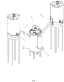
- the embodiment of the present application further discloses a proportioning equipment.
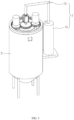
- the proportioning equipment includes a plurality of soaking barrels 1 and a stirring barrel 2.
- the side wall of each soaking barrel 1 is penetrated by a discharge hole 8.
- the discharge hole 8 is defined at the bottom of the soaking barrel 1.
- the first end of the conveying pipe 3 is fixed on the outer wall of the soaking barrel 1 and is in communication with the discharge hole 8.
- the second end of the conveying pipe is in communication with the stirring barrel 2.
- the plant seeds conveyed from different soaking barrels 1 are stirred and mixed in the stirring barrel 2 to facilitate sowing.
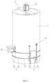
- an adjustment assembly 4 is provided on the outer wall of the soaking barrel 1.
- the adjustment assembly 4 includes an adjustment ring 41 and a transmission wheel 42.
- the outer wall of the soaking barrel 1 is configured with an annular chute 10.
- the adjustment ring 41 is arranged in the chute 10.
- the adjustment ring 41 is penetrated by a throughhole 9.
- the top surface of the adjustment ring 41 is integrally formed with transmission teeth.
- the transmission wheel 42 is arranged in the chute 10.
- the transmission wheel 42 is a gear.
- the transmission wheel 42 is meshed with the transmission teeth.
- a first driving motor 43 is fixed on the outer wall of the soaking barrel 1, the output shaft of the first driving motor 43 is coaxially and fixedly connected to the transmission wheel 42.
- the first driving motor 43 drives the transmission wheel 42 to rotate, which in turn drives the adjustment ring 41 to rotate.
- the throughhole 9 and the discharge hole 8 are gradually communicated.
- the discharge speed of seeds in the soaking barrel 1 is controlled.
- the proportioning of plant seeds is facilitated.
- the outer wall of the soaking barrel 1 is provided with an opening and closing assembly 5.
- the opening and closing assembly 5 is arranged in the conveying pipe 3.
- the opening and closing assembly 5 includes a lifting plate 51, a guide rod 52 and a lifting screw rod 53.
- the guide rod 52 is vertically fixed on the outer wall of the soaking barrel 1.
- the lifting screw rod 53 is vertically fixed on the outer wall of the soaking barrel 1.
- the first end of the lifting plate 51 is screwed to the lifting screw rod 53.
- the second end of the lifting plate is penetrated by a socket for the guide rod 52.
- a second driving motor 54 is fixed on the outer wall of the soaking barrel 1.
- the output shaft of the second driving motor 54 is coaxially and fixedly connected to the lifting screw rod 53.
- the second driving motor 54 drives the lifting screw rod 53 to rotate and in turn drives the lifting plate 51 to lift.
- the initial conveying speed of the seeds in a plurality of soaking barrels 1 is the same.
- the conveying speed of the seeds in the soaking barrels 1 no longer changes, the conveying speed of the seeds in the plurality of soaking barrels 1 are no longer the same, which leads to errors in the proportion of the plant seeds at the beginning.
- the lifting plate 51 After the lifting plate 51 is attached to the outer wall of the adjustment ring 41 and the adjustment ring 41 is adjusted, the lifting plate 51 rises, to connect the throughhole 9 with the conveying pipe 3, so that the initial conveying speeds of the plant seeds are different from each other, thereby improving the accuracy of proportion of plant seeds.
- a pressure regulating cavity 29 is configured in the soaking barrel 1.
- An installation cavity 30 in communication with the pressure regulating cavity 29 is configured in the soaking barrel 1.
- a first piston block 31 is arranged in the pressure regulating cavity 29.
- a second piston block 32 is arranged in the installation cavity 30.
- the side wall of the first piston block 31 is integrally formed with a driven block 34.
- the outer wall of the soaking barrel 1 is configured with a groove 36 in communication with the pressure regulating cavity 29.
- the driven block 34 is arranged in the groove 36 and protrudes from the groove 36.
- a transmission rod 35 is fixed on the bottom surface of the lifting plate 51. The bottom end of the transmission rod 35 is fixedly connected to the driven block 34.
- the lifting plate 51 When the lifting plate 51 rises or sinks, it can drive the driven block 34 to rise or sink, thereby driving the first piston block 31 to slide in the pressure regulating cavity 29.
- the air pressure in the pressure regulating cavity 29 increases, so that the air in the pressure regulating cavity 29 flows toward two installation cavities 30, therefore, the air pressure in the installation cavities 30 increases, so that the second piston block 32 slides upward.
- the lifting plate 51 sinks the pressure in the pressure regulating cavity 29 decreases, so that the second piston block 32 is driven to slide downward.
- the bottom surface of the adjustment ring 41 is provided with locking teeth 44.
- the inner wall of the chute 10 facing the locking teeth 44 is configured with an aperture 38.
- a slider 37 is arranged in the aperture 38.
- One end of slider 37 away from the adjustment ring 41 is fixedly connected to the second piston block 32.
- Limiting teeth 33 are integrally formed on the side of the slider 37 facing the adjustment ring 41. When the slider 37 is driven to rise by the second piston block 32, the limiting teeth 33 can be meshed with the locking teeth 44, thereby preventing the adjustment ring 41 from rotating and improving the stability of the adjustment ring 41 in the chute 10.
- the lifting plate 51 closes the discharge hole 8 at this time, in particular, the first piston block 31 is located at the bottom of the pressure regulating cavity 29, and the slider 37 is accommodated in the aperture 38.
- the first piston block 31 rises with the lifting plate 51, so that the limiting teeth 33 on the slider 37 are gradually meshed with the locking teeth 44 on the adjustment ring 41, so as to prevent the adjustment ring 41 from rotating under the pressure of the plant seeds, thereby improving the stability of the adjustment ring 41.
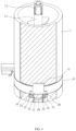
- the bottom of the soaking barrel 1 is configured with a discharge outlet.
- a filter 16 is fixed on the inner wall of the discharge outlet.
- a sealing plate 17 is articulated with the inner wall of the discharge outlet.
- the sealing plate 17 is arranged below the filter 16.
- An air cylinder 18 is articulated with the inner wall of the discharge outlet.
- the piston rod of the gas cylinder 18 is articulated with the end of the sealing plate 17 away from the hinge point where it is articulated with the soaking barrel 1.
- the piston rod of the air cylinder 18 extends, and the sealing plate 17 closes the discharge outlet, such that the seeds can be soaked in the soaking barrel 1.
- the piston rod of the air cylinder 18 is retracted, so that the liquid for soaking is discharged from the discharge outlet, and the filter 16 blocks the plant seeds in the soaking barrel 1.
- one end of the filter 16 close to the discharge hole 8 inclines downward, so that the plant seeds on the filter 16 tend to roll toward the discharge hole 8, which facilitates the transportation of the plant seeds in the soaking barrel 1 to the conveying pipe 3.
- a fixing plate 11 is fixed on the top surface of the soaking barrel 1.
- a third driving motor 14 is fixed on the fixing plate 11.
- the output shaft of the third driving motor 14 extends toward the soaking barrel 1.
- a connecting rod 12 is provided at the bottom of the fixing plate 11.
- the connecting rod 12 is coaxially fixed on the output shaft of the third driving motor 14.
- a stirring blade 13 extending spirally along the length direction of the connecting rod 12 is provided on the side wall of the connecting rod 12.
- a guide ring 15 is fixed on the inner wall of the soaking barrel 1. The inner diameter of the guide ring 15 gradually decreases in the vertical downward direction.
- the third driving motor 14 is started, to drive the connecting rod 12 and the stirring blade 13 to rotate, which facilitates lifting the plant seeds upward, so that the plant seeds surge in the soaking barrel 1.
- Plant seeds are floating around due to the water flow. Under the guidance of the guide ring 15, the plant seeds float toward the connecting rod 12 and the stirring blade 13, which facilitates the reciprocating stirring of the plant seeds.
- the density of the intact seed is greater, while the density of the seed with pests and diseases is smaller.
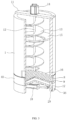
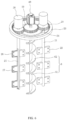
- a stirring assembly 6 is arranged in the stirring barrel 2, and a lifting assembly 7 is provided on the outer wall of the stirring barrel 2.
- the lifting assembly 7 is coupled with the stirring assembly 6, to bring the stirring assembly 6 into the stirring barrel 2 to stir the plant seeds, and to take the stirring assembly 6 from the stirring barrel 2 after the stirring of the plant seeds is completed.
- the lifting assembly 7 includes a lifting oil cylinder 71 and a connecting arm 72.
- the lifting oil cylinder 71 is fixed on the outer wall of the stirring barrel 2.
- the connecting arm 72 is fixed on the piston rod of the lifting oil cylinder 71.
- the stirring assembly 6 is arranged at the bottom of the connecting arm 72.
- the piston rod of the lifting oil cylinder 71 extends and retracts to drive the connecting arm 72 to rise and fall, and thus to drive the stirring assembly 6 to rise and fall.
- the stirring assembly 6 includes a stirring rod 61 and a stirring paddle 62.
- the stirring rod 61 is arranged at the bottom of the connecting arm 72.
- the stirring paddle 62 is fixed on the side wall of the stirring rod 61.
- a fourth driving motor 63 is fixed on the connecting arm 72.
- the output shaft of the fourth driving motor 63 is coaxially and fixedly connected to the stirring rod 61.
- the fourth driving motor 63 drives the stirring rod 61 to rotate, which in turn drives the stirring paddle 62 to stir the plant seeds in the stirring barrel 2 to fully mix different types of plant seeds.
- a supporting plate 24 is fixed on the stirring rod 61.
- a plurality of driven rods 21 are arranged in the stirring barrel 2.
- a driven wheel 20 is coaxially fixed on the driven rod 21.
- the driven wheel 20 is arranged on the supporting plate 24.
- a driving wheel 19 is coaxially fixed on the stirring rod 61. Both the driving wheel 19 and the driven wheel 20 are gears. The driving wheel 19 and the driven wheel 20 are meshed with each other.
- a transmission ring 23 is fixed on the piston rod of the lifting oil cylinder 71.
- the transmission ring 23 is a ring gear, and the transmission ring 23 is meshed with the driven wheel 20.
- a plurality of stirring plates 22 are fixed on the side wall of the driven rod 21.
- a communicating cavity 25 is defined in the driven rod 21.
- a relief cavity 26 in communication with the communicating cavity 25 is defined in the stirring plate 22.
- the side wall of the stirring plate 22 is configured with a plurality of liquid outlets 27 in communication with the relief cavity 26.
- a feeding barrel 28 in communication with the communicating cavity 25 is arranged at the top of the driven rod 21.
- the nutrient solution is accommodated in the feeding barrel 28. While the stirring plate 22 mixes the plant seeds, the nutrient solution is coated on the surface of the plant seeds to facilitate the growth of the plant seeds.
- the implementation principle of the embodiment of the present application is: different plant seeds are placed in different soaking barrels 1 for soaking.
- the third driving motor 14 is started to stir the plant seeds.
- the piston rod of the air cylinder 18 retracts, and the liquid in the soaking barrel 1 is discharged.
- the first driving motor 43 is started to rotate the adjustment ring 41, so as to adjust the communication area between the throughhole 9 and the discharge hole 8.
- the second driving motor 54 is started to lift the lifting plate 51 and to drive the first piston block 31 to rise, so that the limiting teeth 33 are meshed with the locking teeth 44, to transport the plant seeds into the stirring barrel 2.
- the fourth driving motor 63 is started to drive the stirring plate 22 and the stirring paddle 62 to stir the plant seeds.
Landscapes
- Engineering & Computer Science (AREA)
- Mining & Mineral Resources (AREA)
- General Life Sciences & Earth Sciences (AREA)
- Life Sciences & Earth Sciences (AREA)
- Geology (AREA)
- Geochemistry & Mineralogy (AREA)
- Remote Sensing (AREA)
- Paleontology (AREA)
- Civil Engineering (AREA)
- General Engineering & Computer Science (AREA)
- Structural Engineering (AREA)
- Pretreatment Of Seeds And Plants (AREA)
- Sowing (AREA)
Claims (8)
- Verfahren zur ökologischen Wiederherstellung von Grubenvegetation mit lehmähnlichem Material, wobei das Verfahren die folgenden Schritte umfasst:Schritt 1: Befestigen eines Hängenetzes an einer Grubenoberfläche;Schritt 2: Sprüh-Aussaat einer ersten Schicht aus lehmähnlichem Material auf der Grubenoberfläche;Schritt 3: Sprüh-Aussaat einer zweiten Schicht aus lehmähnlichem Material auf der Oberfläche der ersten Schicht aus lehmähnlichem Material;Schritt 4: Aussäen von Strauchsamen auf die Oberfläche der zweiten Schicht aus lehmähnlichem Material und Aussäen von Baumsamen in Abständen auf der Oberfläche der zweiten Schicht aus lehmähnlichem Material, dadurch gekennzeichnet, dass in Schritt 4 das Verfahren die folgenden durch eine Dosierausrüstung durchgeführten Schritte umfasst:einweichen der Strauch- und Baumsamen vor dem Aussäen mittels der Dosierausrüstung, wobei die Dosierausrüstung ein Einweichfass (1) und ein Rührfass (2) umfasst, eine Seitenwand des Einweichfasses (1) mit einer Auslassöffnung(8) versehen ist, ein Förderrohr (3) zwischen dem Einweichfass (1) und dem Rührfass (2) angeordnet ist, und das Förderrohr (3) die Auslassöffnung (8) mit dem Rührfass (2) verbindet;eine Justiereinheit (4) zur Steuerung der Austrittsfläche der Auslassöffnung (8) an einer Außenwand des Einweichfasses (1) vorgesehen ist, und eine Öffnungs- und Schließeinheit (5), an der Außenwand des Einweichfasses (1) vorgesehen ist;eine Rühreinheit (6) im Rührfass (2) angeordnet ist; und eine Hebeeinheit (7) zum Anheben und Absenken der Rühreinheit (6) an einer Außenwand des Rührfasses (2) vorgesehen ist.
- Das Verfahren nach Anspruch 1, dadurch gekennzeichnet, dass die Justiereinheit (4) einen Justierring (41) und ein Übertragungsrad (42) umfasst, wobei die Außenwand des Einweichfasses (1) mit einer Führungsschiene (10) versehen ist, der Justierring (41) in der Führungsschiene (10) angeordnet ist, der Justierring (41) mit einer Durchgangsöffnung (9) versehen ist, die Durchgangsöffnung (9) mit der Auslassöffnung (8) in Verbindung steht, das Übertragungsrad (42) mit dem Justierring (41) gekoppelt ist, um den Justierring (41) in der Führungsschiene (10) zu verschieben und die Außenwand des Einweichfasses (1) mit einem ersten Antriebsmotor (43) ausgestattet ist, der das Übertragungsrad (42) zum Drehen antreibt.
- Das Verfahren nach Anspruch 2, dadurch gekennzeichnet, dass im Einweichfass (1) eine Druckausgleichskammer (29) vorgesehen ist, im Einweichfass (1) eine Installationskammer (30) vorgesehen ist, die mit der Druckausgleichskammer (29) verbunden ist, ein erster Kolbenblock (31) in der Druckausgleichskammer (29) angeordnet ist, und ein zweiter Kolbenblock (32) in der Installationskammer (30) angeordnet ist;eine Unterseite des Justierrings (41) mit Sperrzähnen (44) versehen ist, eine Öffnung (38) in einer Innenwand der Führungsschiene (10) angeordnet ist, die den Sperrzähnen (44) zugewandt ist, ein Gleitstück (37) in der Öffnung (38) angeordnet ist, und Begrenzungszähne (33), die auf einer Seite des Gleitstücks (37) den Sperrzähnen (44) zugewandt angeordnet sind, die Begrenzungszähne derart ausgestaltet sind, dass sie mit den Sperrzähnen (44) koppelbar sind, ein Ende des Gleitstücks (37) abseits der Begrenzungszähne (33) mit dem zweiten Kolbenblock (32) verbunden ist;eine Nut (36), die mit der Druckausgleichskammer (29) in Verbindung steht, die in der Außenwand des Einweichfasses (1) ausgebildet ist, ein Mitnehmerblock (34) der in der Nut (36) angeordnet ist, der Mitnehmerblock (34) mit dem ersten Kolbenblock (31) gekoppelt ist; und der Mitnehmerblock (34) mit der Öffnungs- und Schließeinheit (5) verbunden ist.
- Das Verfahren nach Anspruch 1, dadurch gekennzeichnet, dass die Öffnungs- und Schließeinheit (5) eine Hubplatte (51), eine Führungsstange (52) und eine Hubspindel (53) umfasst, wobei die Führungsstange (52) an der Außenwand des Einweichfasses (1) angeordnet ist, die Hubspindel (53) an der Außenwand des Einweichfasses (1) angeordnet ist und parallel zur Führungsstange (52) ist, ein erstes Ende der Hubplatte (51) mit der Hubspindel (53) verschraubt ist, und ein zweites Ende der Hubplatte von der Führungsstange (52) durchstoßen ist, ein zweiter Antriebsmotor (54) an der Außenwand des Einweichfasses (1) vorgesehen ist, um die Hubspindel (53) zum Drehen anzutreiben.
- Das Verfahren nach Anspruch 1, dadurch gekennzeichnet, dass ein Boden des Einweichfasses (1) mit einem Auslass versehen ist, wobei ein Filter (16) im Auslass angeordnet ist, eine Verschlussplatte (17) im Auslass vorgesehen ist, ein Ende der Verschlussplatte (17) mit einer Innenwand des Einweichfasses (1) gelenkig verbunden ist, ein Luftzylinder (18) am Boden des Einweichfasses (1) angeordnet ist, und eine Kolbenstange des Gaszylinders (18) mit der Verschlussplatte (17) gelenkig verbunden ist;
eine obere Oberfläche des Einweichfasses (1) mit einer Befestigungsplatte (11) versehen ist, eine Unterseite der Befestigungsplatte (11) mit einer Verbindungsstange (12) ausgestattet ist, die Verbindungsstange (12) mit einem Rührblatt (13) versehen ist, ein dritter Antriebsmotor (14) auf der Befestigungsplatte (11) angeordnet ist, um die Verbindungsstange (12) zum Drehen anzutreiben, und eine Innenwand des Einweichfasses (1) mit einem Führungsring (15) ausgestattet ist. - Das Verfahren nach Anspruch 1, dadurch gekennzeichnet, dass die Rühreinheit (6) eine Rührstange (61) und eine Rührschaufel (62) umfasst, wobei die Rührschaufel (62) an einer Seitenwand der Rührstange (61) angeordnet ist, ein vierter Antriebsmotor (63) um die Rührstange (61) zum Drehen anzutreiben an einer Oberseite der Rührstange (61) vorgesehen ist, und der vierte Antriebsmotor (63) mit der Hebeeinheit (7) gekoppelt ist.
- Das Verfahren nach Anspruch 6, dadurch gekennzeichnet, dass die Rührstange (61) mit einem Antriebsrad (19) versehen ist, die Rührstange (61) eine Stützplatte (24) aufweist, eine Mehrzahl von Mitnehmerstangen (21) im Rührfass (2) angeordnet ist, eine Seitenwand jeder der Mehrzahl von Mitnehmerstangen (21) mit einer Mehrzahl von Rührplatten (22) ausgestattet ist, jede der Mehrzahl von Mitnehmerstangen (21) mit einem Mitnehmerrad (20) versehen ist, das Mitnehmerrad (20) mit dem Antriebsrad (19) gekoppelt ist, ein Übertragungsring (23) an einer Oberseite des Rührfasses (2) vorgesehen ist, das Mitnehmerrad (20) in Übertragungsverbindung mit dem Übertragungsring (23) steht;
eine Verbindungskammer (25) in jeder der Mehrzahl von Mitnehmerstangen (21) ausgebildet ist, eine Druckentlastungskammer (26), die mit der Verbindungskammer (25) in Verbindung steht, in jeder der Mehrzahl von Rührplatten (22) vorgesehen ist, eine Seitenwand jeder der Mehrzahl von Rührplatten (22) mit einer Mehrzahl von Flüssigkeitsaustrittsöffnungen (27) versehen ist, die mit der Druckentlastungskammer (26) in Verbindung steht, und ein Zuführfass (28) an einer Oberseite jeder der Mehrzahl von Mitnehmerstangen (21) angeordnet ist, das mit der Verbindungskammer (25) verbunden ist. - Das Verfahren nach Anspruch 1, dadurch gekennzeichnet, dass die Hebeeinheit (7) einen Hubölzylinder (71) und einen Verbindungsarm (72) umfasst, wobei der Verbindungsarm (72) an einer Kolbenstange des Hubölzylinders (71) angeordnet ist, und der Verbindungsarm (72) mit der Rühreinheit (6) gekoppelt ist.
Applications Claiming Priority (1)
| Application Number | Priority Date | Filing Date | Title |
|---|---|---|---|
| CN202310087109.2A CN115868361B (zh) | 2023-02-08 | 2023-02-08 | 使用类壤土恢复矿山植被生态的方法 |
Publications (3)
| Publication Number | Publication Date |
|---|---|
| EP4414532A1 EP4414532A1 (de) | 2024-08-14 |
| EP4414532C0 EP4414532C0 (de) | 2025-05-14 |
| EP4414532B1 true EP4414532B1 (de) | 2025-05-14 |
Family
ID=85760934
Family Applications (1)
| Application Number | Title | Priority Date | Filing Date |
|---|---|---|---|
| EP24150517.1A Active EP4414532B1 (de) | 2023-02-08 | 2024-01-05 | Verfahren zur ökologischen wiederherstellung von minengetariatin mit simulationsloam |
Country Status (3)
| Country | Link |
|---|---|
| EP (1) | EP4414532B1 (de) |
| CN (1) | CN115868361B (de) |
| BE (1) | BE1031283B1 (de) |
Families Citing this family (2)
| Publication number | Priority date | Publication date | Assignee | Title |
|---|---|---|---|---|
| CN116897648B (zh) * | 2023-09-11 | 2023-12-22 | 内蒙古中汇泰和工程有限公司 | 一种用于退化矿山的植被恢复辅助装置及使用方法 |
| CN119018503A (zh) * | 2024-10-30 | 2024-11-26 | 山东星阳生物科技有限公司 | 一种炭基肥储藏容器及储藏工艺 |
Family Cites Families (17)
| Publication number | Priority date | Publication date | Assignee | Title |
|---|---|---|---|---|
| KR200159948Y1 (ko) * | 1997-04-30 | 1999-11-01 | 권세영 | 두부 자동 성형장치에 있어서의 간수 공급장치 |
| CN1566543A (zh) * | 2003-07-07 | 2005-01-19 | 叶建军 | 一种岩土边坡植被重建的方法 |
| JP5307363B2 (ja) * | 2007-07-17 | 2013-10-02 | 邦夫 佐々木 | 砕砂製造装置 |
| CN105981539A (zh) * | 2015-02-04 | 2016-10-05 | 深圳市铁汉生态环境股份有限公司 | 一种边坡绿化方法 |
| CN109328518A (zh) * | 2018-08-20 | 2019-02-15 | 江苏绿岩生态技术股份有限公司 | 一种煤矿矸石山的生态修复方法 |
| CN208768395U (zh) * | 2018-08-24 | 2019-04-23 | 酒泉阿树农业生物科技有限责任公司 | 一种可调配种衣剂及种子用量的苜蓿种子包衣机 |
| CN112293123A (zh) * | 2019-07-25 | 2021-02-02 | 江苏绿岩生态技术股份有限公司 | 一种坡面修复方法 |
| CN110521503B (zh) * | 2019-08-07 | 2021-09-17 | 叶建军 | 湿喷植被混凝土生态护坡技术 |
| CN211267610U (zh) * | 2019-12-18 | 2020-08-18 | 中卫市三隆农业发展有限公司 | 温汤浸种装置 |
| CN212549401U (zh) * | 2020-04-17 | 2021-02-19 | 余姚市恒祥新型建材有限公司 | 一种搅拌机 |
| CN112272990A (zh) * | 2020-11-25 | 2021-01-29 | 德州学院 | 一种农业育苗用浸种装置 |
| CN214319998U (zh) * | 2020-12-30 | 2021-10-01 | 江西波诗明科技实业有限公司 | 一种水性油漆配比装置 |
| CN113812238B (zh) * | 2021-08-25 | 2022-11-11 | 华南理工大学 | 一种矿山石场植被生态修复方法 |
| CN113908733A (zh) * | 2021-10-18 | 2022-01-11 | 常州都铂高分子有限公司 | 一种可降解压敏胶生产装置及生产方法 |
| CN217511208U (zh) * | 2022-04-12 | 2022-09-30 | 贵州绿太阳制药有限公司 | 一种搅拌反应罐 |
| CN114618354B (zh) * | 2022-04-13 | 2024-03-01 | 江苏可易木业有限公司 | 一种造纸用的纸浆搅拌装置 |
| CN218244353U (zh) * | 2022-08-01 | 2023-01-10 | 湖北尖兵农业科技服务有限公司 | 一种循环恒温种子浸种装置 |
-
2023
- 2023-02-08 CN CN202310087109.2A patent/CN115868361B/zh active Active
-
2024
- 2024-01-05 EP EP24150517.1A patent/EP4414532B1/de active Active
- 2024-01-09 BE BE20245007A patent/BE1031283B1/de active IP Right Grant
Also Published As
| Publication number | Publication date |
|---|---|
| EP4414532C0 (de) | 2025-05-14 |
| BE1031283A1 (de) | 2024-08-14 |
| CN115868361A (zh) | 2023-03-31 |
| CN115868361B (zh) | 2023-10-03 |
| BE1031283B1 (de) | 2024-12-11 |
| EP4414532A1 (de) | 2024-08-14 |
Similar Documents
| Publication | Publication Date | Title |
|---|---|---|
| EP4414532B1 (de) | Verfahren zur ökologischen wiederherstellung von minengetariatin mit simulationsloam | |
| AU2020101714A4 (en) | Lycium barbarum orchard grass planting method | |
| CN108834628A (zh) | 利用水泥毯板固定植被混凝土的垂直坡面绿化装置及方法 | |
| CN117397436A (zh) | 一种高效菠萝种植装置及菠萝种植机 | |
| CN101518186A (zh) | 采矿迹地植被恢复与重建方法 | |
| CN116369006B (zh) | 一种梭梭树智能插种机 | |
| CN104770270A (zh) | 一种边坡防护中的灌木建植方法及其护苗罩 | |
| CN115152471A (zh) | 一种露天矿山采后高陡岩质边坡生态恢复技术 | |
| CN223463435U (zh) | 已支护岩质边坡复绿结构 | |
| CN109537572B (zh) | 一种利用蜂窝式聚水穴治理沙漠的方法 | |
| CN108834813B (zh) | 一种玫瑰的栽培方法 | |
| CN217470929U (zh) | 一种用于园林绿化林木养防装置 | |
| CN119678691A (zh) | 一种作物种植施肥自动化一体设备 | |
| KR100860241B1 (ko) | 비탈면의 녹화방법 | |
| CN204570710U (zh) | 一种生态护坡系统 | |
| CN109537573B (zh) | 一种原生态沙漠治理方法及装置 | |
| CN106879427A (zh) | 李子树的种植方法 | |
| CN106465627A (zh) | 一种高产苹果的栽培方法 | |
| CN117322200A (zh) | 一种沙拐枣育苗方法及其装置 | |
| CN215223328U (zh) | 一种规模化快速植树装置 | |
| CN112602494B (zh) | 一种规模化快速植树装置及植树方法 | |
| CN116005696B (zh) | 一种林业种植用植被绿化坡及修建方法 | |
| CN220570958U (zh) | 一种环境建设用绿化种植设备 | |
| KR100970189B1 (ko) | 그린복합토를 이용한 사면 녹화공법 | |
| CN218125517U (zh) | 一种园林绿化施肥装置 |
Legal Events
| Date | Code | Title | Description |
|---|---|---|---|
| PUAI | Public reference made under article 153(3) epc to a published international application that has entered the european phase |
Free format text: ORIGINAL CODE: 0009012 |
|
| STAA | Information on the status of an ep patent application or granted ep patent |
Free format text: STATUS: EXAMINATION IS IN PROGRESS |
|
| 17P | Request for examination filed |
Effective date: 20240105 |
|
| AK | Designated contracting states |
Kind code of ref document: A1 Designated state(s): AL AT BE BG CH CY CZ DE DK EE ES FI FR GB GR HR HU IE IS IT LI LT LU LV MC ME MK MT NL NO PL PT RO RS SE SI SK SM TR |
|
| GRAP | Despatch of communication of intention to grant a patent |
Free format text: ORIGINAL CODE: EPIDOSNIGR1 |
|
| STAA | Information on the status of an ep patent application or granted ep patent |
Free format text: STATUS: GRANT OF PATENT IS INTENDED |
|
| INTG | Intention to grant announced |
Effective date: 20250102 |
|
| GRAS | Grant fee paid |
Free format text: ORIGINAL CODE: EPIDOSNIGR3 |
|
| GRAA | (expected) grant |
Free format text: ORIGINAL CODE: 0009210 |
|
| STAA | Information on the status of an ep patent application or granted ep patent |
Free format text: STATUS: THE PATENT HAS BEEN GRANTED |
|
| AK | Designated contracting states |
Kind code of ref document: B1 Designated state(s): AL AT BE BG CH CY CZ DE DK EE ES FI FR GB GR HR HU IE IS IT LI LT LU LV MC ME MK MT NL NO PL PT RO RS SE SI SK SM TR |
|
| REG | Reference to a national code |
Ref country code: GB Ref legal event code: FG4D |
|
| REG | Reference to a national code |
Ref country code: CH Ref legal event code: EP |
|
| REG | Reference to a national code |
Ref country code: IE Ref legal event code: FG4D |
|
| REG | Reference to a national code |
Ref country code: DE Ref legal event code: R096 Ref document number: 602024000117 Country of ref document: DE |
|
| REG | Reference to a national code |
Ref country code: CH Ref legal event code: PK Free format text: BERICHTIGUNGEN |
|
| RIN2 | Information on inventor provided after grant (corrected) |
Inventor name: SHEN, YIFENG Inventor name: ZHANG, LUER Inventor name: ZHANG, BO |
|
| U01 | Request for unitary effect filed |
Effective date: 20250611 |
|
| U07 | Unitary effect registered |
Designated state(s): AT BE BG DE DK EE FI FR IT LT LU LV MT NL PT RO SE SI Effective date: 20250620 |
|
| PG25 | Lapsed in a contracting state [announced via postgrant information from national office to epo] |
Ref country code: ES Free format text: LAPSE BECAUSE OF FAILURE TO SUBMIT A TRANSLATION OF THE DESCRIPTION OR TO PAY THE FEE WITHIN THE PRESCRIBED TIME-LIMIT Effective date: 20250514 |
|
| PG25 | Lapsed in a contracting state [announced via postgrant information from national office to epo] |
Ref country code: NO Free format text: LAPSE BECAUSE OF FAILURE TO SUBMIT A TRANSLATION OF THE DESCRIPTION OR TO PAY THE FEE WITHIN THE PRESCRIBED TIME-LIMIT Effective date: 20250814 Ref country code: GR Free format text: LAPSE BECAUSE OF FAILURE TO SUBMIT A TRANSLATION OF THE DESCRIPTION OR TO PAY THE FEE WITHIN THE PRESCRIBED TIME-LIMIT Effective date: 20250815 |
|
| PG25 | Lapsed in a contracting state [announced via postgrant information from national office to epo] |
Ref country code: PL Free format text: LAPSE BECAUSE OF FAILURE TO SUBMIT A TRANSLATION OF THE DESCRIPTION OR TO PAY THE FEE WITHIN THE PRESCRIBED TIME-LIMIT Effective date: 20250514 |
|
| PG25 | Lapsed in a contracting state [announced via postgrant information from national office to epo] |
Ref country code: HR Free format text: LAPSE BECAUSE OF FAILURE TO SUBMIT A TRANSLATION OF THE DESCRIPTION OR TO PAY THE FEE WITHIN THE PRESCRIBED TIME-LIMIT Effective date: 20250514 |
|
| PG25 | Lapsed in a contracting state [announced via postgrant information from national office to epo] |
Ref country code: RS Free format text: LAPSE BECAUSE OF FAILURE TO SUBMIT A TRANSLATION OF THE DESCRIPTION OR TO PAY THE FEE WITHIN THE PRESCRIBED TIME-LIMIT Effective date: 20250814 |
|
| PG25 | Lapsed in a contracting state [announced via postgrant information from national office to epo] |
Ref country code: IS Free format text: LAPSE BECAUSE OF FAILURE TO SUBMIT A TRANSLATION OF THE DESCRIPTION OR TO PAY THE FEE WITHIN THE PRESCRIBED TIME-LIMIT Effective date: 20250914 |
|
| PG25 | Lapsed in a contracting state [announced via postgrant information from national office to epo] |
Ref country code: SM Free format text: LAPSE BECAUSE OF FAILURE TO SUBMIT A TRANSLATION OF THE DESCRIPTION OR TO PAY THE FEE WITHIN THE PRESCRIBED TIME-LIMIT Effective date: 20250514 |
|
| PG25 | Lapsed in a contracting state [announced via postgrant information from national office to epo] |
Ref country code: CZ Free format text: LAPSE BECAUSE OF FAILURE TO SUBMIT A TRANSLATION OF THE DESCRIPTION OR TO PAY THE FEE WITHIN THE PRESCRIBED TIME-LIMIT Effective date: 20250514 |
|
| PG25 | Lapsed in a contracting state [announced via postgrant information from national office to epo] |
Ref country code: SK Free format text: LAPSE BECAUSE OF FAILURE TO SUBMIT A TRANSLATION OF THE DESCRIPTION OR TO PAY THE FEE WITHIN THE PRESCRIBED TIME-LIMIT Effective date: 20250514 |
|
| U20 | Renewal fee for the european patent with unitary effect paid |
Year of fee payment: 3 Effective date: 20260129 |
|
| PLBE | No opposition filed within time limit |
Free format text: ORIGINAL CODE: 0009261 |
|
| STAA | Information on the status of an ep patent application or granted ep patent |
Free format text: STATUS: NO OPPOSITION FILED WITHIN TIME LIMIT |
|
| REG | Reference to a national code |
Ref country code: CH Ref legal event code: L10 Free format text: ST27 STATUS EVENT CODE: U-0-0-L10-L00 (AS PROVIDED BY THE NATIONAL OFFICE) Effective date: 20260325 |
|
| 26N | No opposition filed |
Effective date: 20260217 |