EP4413285B1 - Gehäuse für elektromagnetische ventile, rohrförmiges element und zugehöriges elektromagnetisches ventil - Google Patents
Gehäuse für elektromagnetische ventile, rohrförmiges element und zugehöriges elektromagnetisches ventil Download PDFInfo
- Publication number
- EP4413285B1 EP4413285B1 EP22790067.7A EP22790067A EP4413285B1 EP 4413285 B1 EP4413285 B1 EP 4413285B1 EP 22790067 A EP22790067 A EP 22790067A EP 4413285 B1 EP4413285 B1 EP 4413285B1
- Authority
- EP
- European Patent Office
- Prior art keywords
- housing
- locking system
- configuration
- coil
- tubular element
- Prior art date
- Legal status (The legal status is an assumption and is not a legal conclusion. Google has not performed a legal analysis and makes no representation as to the accuracy of the status listed.)
- Active
Links
Images


Classifications
-
- F—MECHANICAL ENGINEERING; LIGHTING; HEATING; WEAPONS; BLASTING
- F16—ENGINEERING ELEMENTS AND UNITS; GENERAL MEASURES FOR PRODUCING AND MAINTAINING EFFECTIVE FUNCTIONING OF MACHINES OR INSTALLATIONS; THERMAL INSULATION IN GENERAL
- F16K—VALVES; TAPS; COCKS; ACTUATING-FLOATS; DEVICES FOR VENTING OR AERATING
- F16K31/00—Actuating devices; Operating means; Releasing devices
- F16K31/02—Actuating devices; Operating means; Releasing devices electric; magnetic
- F16K31/06—Actuating devices; Operating means; Releasing devices electric; magnetic using a magnet, e.g. diaphragm valves, cutting off by means of a liquid
- F16K31/0675—Electromagnet aspects, e.g. electric supply therefor
-
- F—MECHANICAL ENGINEERING; LIGHTING; HEATING; WEAPONS; BLASTING
- F16—ENGINEERING ELEMENTS AND UNITS; GENERAL MEASURES FOR PRODUCING AND MAINTAINING EFFECTIVE FUNCTIONING OF MACHINES OR INSTALLATIONS; THERMAL INSULATION IN GENERAL
- F16K—VALVES; TAPS; COCKS; ACTUATING-FLOATS; DEVICES FOR VENTING OR AERATING
- F16K27/00—Construction of housing; Use of materials therefor
- F16K27/02—Construction of housing; Use of materials therefor of lift valves
- F16K27/029—Electromagnetically actuated valves
-
- H—ELECTRICITY
- H01—ELECTRIC ELEMENTS
- H01F—MAGNETS; INDUCTANCES; TRANSFORMERS; SELECTION OF MATERIALS FOR THEIR MAGNETIC PROPERTIES
- H01F7/00—Magnets
- H01F7/06—Electromagnets; Actuators including electromagnets
- H01F7/08—Electromagnets; Actuators including electromagnets with armatures
- H01F7/16—Rectilinearly-movable armatures
- H01F7/1607—Armatures entering the winding
Definitions
- the present invention relates to a housing, adapted to be comprised in a tubular element for electromagnetic valves, which comprises an innovative coil locking system.
- the present invention also relates to a tubular element comprising a housing according to the present invention.
- the present invention further relates to an electromagnetic valve having a housing according to the present invention comprised in a tubular element assembled to the valve body.
- electromagnetic valves comprise a coil adapted to move a core for controlling a shutter or diaphragm element, whether such electromagnetic valve is of the direct or indirect type. Said coil must be firmly assembled to the electromagnetic valve, so that it cannot be accidentally removed.
- locking systems are currently known in the art.
- locking systems are known which are integrated into the structure or housing where the core is housed, the latter being adapted to slide within the housing.
- Such type of locking systems is inexpensive and easy to manufacture, but suffers from the drawback that the coil and said housing cannot be separated again once they have been coupled together.
- Such an implementation does not allow testing the coil and/or the electromagnetic valve to verify their proper operation prior to irremovably fixing said coil to the housing structure.
- the expression “irremovably fixing” refers to the fact that the coupling cannot be undone without irreversibly damaging, e.g. breaking, either one of the two parts.
- External locking systems are also known, which are adapted to be associated with said structure or housing, and which make it possible to selectively lock the coil in position and allow it to be subsequently removed while keeping its structural and/or functional characteristics unchanged.
- Such locking systems are external elements, e.g. snap rings, that can be removably coupled to said housing.
- Such a solution although it permits removing the coil, if necessary, without impairing the structural integrity of either the coil or the case, or of the locking system itself, is costly because it is an element that is normally manufactured separately using a material that is more expensive than the traditional plastic materials usually employed for making such housings.
- it since it is an external element, it increases the production costs because an additional step is needed in order to secure the locking system to the housing.
- Patent application GB2296075A discloses a valve unit comprising a first cup-shaped element made of plastic material with a base that has an external axial shank in which a longitudinal duct is formed between the seat of the pilot valve and a distal vent opening; and a second annular element of plastic material is anchored around the shank of the first element and is secured thereto by ultrasonic welding.
- Patent application EP0840048A1 discloses a solenoid actuated valve having a magnetic armature slidably received in a closed guide member secured to the valve body by a spin welded ring; said armature guide has external peripheral teeth which interengage corresponding internal teeth on the solenoid coil assembly to permit any desired rotational orientation of the coil when assembled onto the guide.
- the coil assembly is secured in the desired rotational position by interengagement of the teeth and is secured axially by snap tabs formed on the end of the guide.
- application FR2552582A3 discloses an actuating set for electrovalves comprising an energising element of tubular shape, with an electrical winding for control of the electrovalve, and a support made of stamped material with a profiled appendage passing through the inner cavity of the energising element and provided, at its free end, with elastic reliefs cooperating with the rim of the corresponding extreme opening of the energising element, so as to oppose the movement of extraction of the element with respect to the support;
- the energising element is provided with an annular groove which extends along the rim and defines a sharp ridge turned towards the inner cavity of the energising element and cooperating, by friction, with the elastic reliefs of the support.
- the present invention aims at solving these and other technical problems by providing a housing comprising an innovative locking system.
- the locking system according to the present invention combines the advantages of integrated locking systems, as concerns production and assembly costs, with the advantages offered by removable locking systems, without however being affected by the drawbacks of the latter.
- One aspect of the present invention relates to a housing having the features set out in the appended claim 1.
- Another aspect of the present invention relates to a tubular element for electromagnetic valves having the features set out in the appended claim 8.
- a further aspect of the present invention relates to an electromagnetic valve having the features set out in the appended claim 11.
- reference numeral 4 designates as a whole a housing according to the present invention.
- Reference numeral 3 designates a tubular element for electromagnetic valves according to the present invention.
- reference numeral 1 designates as a whole an electromagnetic valve according to the present invention.
- Housing 4 according to the present invention is particularly suitable for use in electromagnetic valves 1.
- Said housing 4 is adapted to internally receive a core 12.
- Said housing 4 allows said core 12 to slide therein for switching said electromagnetic valve 1.
- At least a portion of said housing 4 is adapted to be surrounded by a coil 11 comprised in electromagnetic valve 1.
- Said housing 4 according to the present invention extends along an axis "L".
- Said housing 4 according to the present invention comprises a distal end 41A and an open proximal end 41B.
- Housing 4 according to the present invention comprises a locking system 44 adapted to lock said coil 11. Said locking system 44 is integrated into said housing 4. Said locking system 44 is, advantageously, located at distal end 41A of said housing 4.
- Said locking system 44 is adapted to assume at least a first configuration and a second configuration.
- said locking system 44 allows said coil 11 to be positioned around and/or removed from said at least a portion of said housing 4.
- said locking system 44 locks said coil 11 around said at least a portion of said housing 4, in particular preventing the removal and/or insertion thereof.
- the present solution makes it possible to replace coil 11 easily and quickly in case of need.
- the present solution makes it possible to selectively remove or position said coil 11 around said housing, so that the coil itself and/or electrovalve 1 in which it is included can be tested prior to locking said coil 11 around at least a portion of said housing 4.
- the present solution allows said coil 11 to be easily and quickly recovered in the event that said housing 4 has some structural defects.
- locking said coil 11 means that said coil 11 cannot be subsequently separated from said housing 4, unless said locking system 4 is broken, in which case it cannot be reused.
- Housing 4 according to the present invention can thus be selectively coupled to a coil 11.
- Figures 3A and 3B show one possible, but merely illustrative and non-limiting, embodiment of a coil and a housing according to the present invention in two different configurations.
- Figure 3A shows coil 11 separated from housing 4 according to the present invention.
- coil 11 has a substantially cylindrical shape that defines a through hole into which said housing 4 can be at least partially inserted, in particular by inserting distal end 41A of housing 4, particularly of cylindrical portion 41 thereof.
- Figure 3A shows other construction details of one possible, but merely illustrative and non-limiting, embodiment of housing 4, which will be further described below.
- said housing 4 extends along an axis "L" and comprises a cylindrical portion 41 having a distal end 41A, preferably closed, and a proximal end 41B, preferably open.
- Said housing 4 further comprises a sealing portion 42, which is adapted to cooperate with a sealing element (14, 16) comprised in electromagnetic valve 1.
- Said sealing portion 42 is located at proximal end 41B of cylindrical portion 41.
- FIG 3A also shows one possible embodiment of locking system 44, which is integrated into said housing 4.
- said locking system 44 is located at distal end 41A of said housing 4.
- locking system 44 integrated into said housing 4" means that said locking system 44 is part of housing 4, since it cannot be separated from the latter without breaking and/or impairing the function of either component.
- FIG 3B shows coil 11 fitted around housing 4 according to the present invention.
- a portion of housing 4 in particular the cylindrical portion, has been inserted into the through hole of coil 11 up to its proximal end 41B.
- said coil 11 has been slid along said axis "L" until it has come in abutment with sealing portion 42 of housing 4.
- said locking system 44 is adapted to assume a first configuration, in which it allows said coil 11 to be positioned around and/or removed from said at least a portion of said housing 4.
- Figure 4A shows, by way of non-limiting example, one possible embodiment of coil 11 and of housing 4 according to the present invention in which said coil 11 is positioned around said housing 4 and locking system 44 is in a first configuration.
- locking system 44 allows said coil 11 to be positioned around and/or removed from said at least a portion of said housing 4 an infinite number of times.
- said coil 11 can be positioned or removed by, for example, sliding it along said axis "L".
- said locking system 44 of housing 4 is adapted to assume a second configuration, different from said first configuration, in which it locks said coil 11 once it has been positioned around said at least a portion of said housing 4 and/or prevents it from being fitted around said housing. In this configuration of locking system 44, coil 11 cannot be separated from said housing 4.
- Figure 4B shows, by way of non-limiting example, one possible embodiment of locking system 44 in a second configuration, in which said locking system 44 locks said coil 11 around said at least a portion of said housing 4, preventing it from being separated.
- said second configuration differs from said first configuration from both a functional viewpoint and a mechanical/structural viewpoint.
- said locking system 44 is in said first configuration.
- the embodiment of locking system 4 illustrated in Figure 4B acts upon an end of coil 11, in particular upon that end which is opposite the end of coil 11 that abuts against said sealing portion of housing 4.
- housing 4 According to the present invention and some possible embodiments thereof, wherein said locking system 44 is made, in a preferred embodiment thereof, as one piece with said housing 4.
- locking system 44 is formed in the body of said housing 4, avoids having to assemble locking system 44 to housing 4.
- said locking system 44 and said housing 4 are a monolithic body.
- the term monolithic body means that said locking system 44 and said housing 4 are formed in the same body, e.g. during the same production process, e.g. a moulding process.
- locking system 44 and housing 4 are a monolithic body, permits speeding up the production of housing 4 according to the present invention, resulting in higher productivity and lower costs incurred for manufacturing housing 4.
- said locking system 44 is adapted to assume at least two distinct configurations, in particular: a first configuration, in which it allows said coil 11 to be positioned around and/or removed from said at least a portion of housing 4; and a second configuration, different from said first configuration, in which it locks said coil 11 around said at least a portion of housing 4, in particular around said cylindrical portion 41.
- said locking system 44 is reversible and allows switching from one configuration to the other. Said embodiment permits switching from the first configuration to the second configuration, and then returning into the first configuration, preferably while keeping the characteristics of locking system 44 unchanged.
- Said embodiment permits recovering said housing 4 and/or said coil 11 should either one of such two parts be defective or malfunctioning, so that the other part can be reused.
- said locking system 44 is non-reversible, i.e. said locking system 44 is designed to prevent, once said second configuration has been assumed, returning to said first configuration.
- Such an embodiment is easy to manufacture and inexpensive.
- housing 4 has a body 40, which defines at least said cylindrical portion 41.
- said locking system 44 is integrated into the distal end of cylindrical portion 41 of body 40 of housing 4.
- Said locking system 44 is adapted to lock coil 11, comprised in electromagnetic valve 1, around cylindrical portion 41 of housing 4.
- said locking system 44 has, in said first configuration, an outside diameter "D" of a known value, allowing said coil 11 to be positioned around and/or removed from cylindrical portion 41.
- said locking system 44 has, in said second configuration, an outside diameter "D" which is greater than said known value, thus locking said coil 11 around cylindrical portion 41 of housing 4.
- said housing 4 comprises: a cylindrical portion 41 and a sealing portion 42, which, for example, define said body 40.
- said cylindrical portion 41 has a known outside diameter "d". Said cylindrical portion 41 extends, as aforementioned, along said axis "L". Even more specifically, said cylindrical portion 41 comprises a distal end 41A, preferably closed, and a proximal end 41B, the latter being open. Preferably, said distal end 41A of cylindrical portion 41 is closed.
- Said sealing portion 42 of housing 4 is adapted to cooperate with a sealing element (14, 16) comprised in electromagnetic valve 1.
- to cooperate means that said sealing portion 42 interacts, whether directly or indirectly, with a sealing element, such as, for example, a diaphragm 14 or a shutter 16, to ensure the proper operation of electromagnetic valve 1 when the latter is switched.
- a sealing element such as, for example, a diaphragm 14 or a shutter 16
- Said sealing portion 42 of housing 4 is arranged at the open proximal end 41B of cylindrical portion 41.
- said sealing portion 42 is made as one monolithic piece together with said cylindrical portion 41, preferably defining said body 40.
- said locking system 44 is made as one piece with said cylindrical portion 41 of housing 4.
- said housing 4 comprises a body 40, preferably a monolithic one.
- Said body 40 of the housing 4 comprises said cylindrical portion 41 and said sealing portion 42.
- said cylindrical portion 41 has a closed distal end 41A and an open proximal end 41B.
- distal end 41A of housing 4, in particular of cylindrical portion 41 is that end of housing 4 which is farthest from a valve body 2 when said housing 4, or tubular element 3, is assembled to valve body 2 of an electromagnetic valve 1.
- Said proximal end 41B of housing 4, in particular of cylindrical portion 41 is that end of housing 4 which is closest to valve body 2 when said housing 4, or tubular element 3, is assembled to valve body 2.
- said sealing portion 42 is adapted to act, even only partly, upon a diaphragm element 14, the latter being adapted to be arranged in a seat defined by said sealing portion 42, in connection with said sealing portion 42.
- said sealing portion 42 advantageously has a circular profile defining a dome-shaped structure that joins said cylindrical portion 41 of housing 4. This embodiment facilitates assembling housing 4 and diaphragm element 14 to valve body 2 of electrovalve 1.
- said sealing portion 42 is adapted to define at least one stopper element of a shutter 16.
- said sealing portion 42 is located at the open proximal end of cylindrical portion 41.
- said sealing portion 42 has a tapered shape, e.g. a dome-like shape.
- said locking system 44 has, in said first configuration, an outside diameter "D" of a known value. In the same embodiment, said locking system 44 has, in said second configuration, an outside diameter "D" which is greater than said known value.
- the present embodiment permits changing the diameter of said locking system 44 when switching from said first configuration to said second configuration, so as to eliminate the possibility of removing coil 11 once it has been positioned around said housing 4.
- the increased outside diameter "D" of locking system 44 can interact with said coil 11, preventing its removal, at one end of said coil 11, as in the embodiments illustrated herein, and/or in a central portion of the structure of said coil 11.
- said locking system 44 maintains said known outside diameter "D" as said coil 11 is positioned around said housing 4 and also as said coil 11 is removed from said housing 4.
- the variation, in particular the increase, in outside diameter "D" of said locking system 44 when switching from said first configuration to said second configuration is due to a stable variation that occurs in the structure of locking system 44.
- stable variation refers to a variation that is permanent over time, excluding any astable variation, e.g. a temporary deformation caused by the movement made for coupling housing 4 with coil 11, e.g. during the movements along axis "L".
- said locking system 44 is designed in such a way that, once said second configuration has been assumed, it will be impossible to assume said first configuration again.
- locking system 44 undergoes, for example, a plastic deformation, in particular an irreversible deformation.
- an "irreversible deformation” is a deformation that does not permit returning to the previous configuration without causing locking system 44 to break or lose its functionality.
- said locking system 44 is designed to allow switching between said second configuration and said first configuration, and vice versa, preferably at least once. In said embodiment, the switching between configurations is reversible.
- said locking system 44 comprises: at least one body 440 having a cylindrical shape; at least one first yielding portion 442 and at least one second yielding portion 444.
- said at least one first yielding portion 442 is adapted to allow a movement of said body 440 along said axis "L" at least while switching from the first configuration to said second configuration of the locking system 44.
- said at least one second yielding portion 444 is adapted to allow increasing an outside diameter "D" of locking system 44 once it has assumed said second configuration.
- said locking system 44 can be selectively made to assume at least two possible values of outside diameter "D", different from each other.
- outside diameter "D" assumed in said first configuration of locking system 44 is smaller than outside diameter "D" assumed in said second configuration.
- a gripping element 441 is comprised which is located at distal end 41A of housing 4.
- said gripping element 441 is adapted to interact with said body 440 in order to change the diameter of locking system 44.
- said first yielding portion 442 connects said body 440 mechanically to said gripping element 441.
- said yielding portion 442 is a portion adapted to become elastically deformed; or said yielding portion 442 is a breaking point, preferably a fracture portion, being adapted to be fractured to allow a movement of said body 440 along said axis "L".
- said second yielding portion 444 is formed in body 440 and allows said body 440 to undergo a deformation that increases its outside diameter "D" as it interacts with said gripping element 441.
- said second yielding portion 444 is adapted to become elastically deformed; or said second yielding portion 444 is a breaking point, being adapted to be fractured in order to weaken the structure of body 440 and allow said body 440 to undergo a deformation that increases its outside diameter "D" as it interacts with said gripping element 441.
- said gripping element 441 is a protrusion that, in the first configuration of locking system 44, is connected to body 440 through said first yielding portion 442. In the second configuration of locking system 44, the same gripping element 441 interacts with said body 440 by interference, e.g. by friction, in order to prevent the separation thereof.
- said first yielding portion 442 when switching between said first configuration and said second configuration of locking system 44, said first yielding portion 442 is adapted to be fractured, thus allowing said body 440 to move relative to said gripping element 441.
- said body 440 comprises an annular portion.
- said second yielding portion 444 is adapted to become deformed, preferably by fracturing, thus allowing said body 440 to increase its outside diameter "D", in particular the diameter of said annular portion, so that it can interact with said gripping element 441 by surrounding it at least partially.
- the interaction between said body 440 and said gripping element 441 is such that it allows said body 440 to deform, thereby increasing its outside diameter "D", while at the same time interacting by interference, e.g. by friction, so as to prevent the separation of said body 440 once said second configuration of locking system 44 has been reached.
- a force on said locking system 44 e.g. a thrust force on said body 440, along said axis "L" towards proximal end 41B of housing 4.
- a force on said locking system 44 e.g. a thrust force on said body 440, along said axis "L" towards proximal end 41B of housing 4.
- Such force is, for example, adapted to fracture said first yielding portion 442 and deform the second yielding portion 444, fracturing it at least partially, so that body 440, as it interacts with said gripping element 441, will increase its own outside diameter "D" and interact by interference with said gripping element 441, thus ensuring that coil 11 will be locked around said housing 4.
- FIG. 5A shows a side view of one possible embodiment of housing 4, which comprises a locking system 44 according to one possible, but merely illustrative and non-limiting, embodiment thereof.
- Locking system 44 illustrated in Figure 5A is in the first configuration, in which it allows said coil 11 to be positioned around and/or removed from said at least a portion of said housing 4.
- the drawing shows said housing 4 as comprising a cylindrical portion 41 having a second end 41B from which said dome-shaped sealing portion 42 extends.
- Said cylindrical portion 41 has a known outside diameter "d”.
- At distal end 41A there is said locking system 44 which has a known outside diameter "D” that is substantially similar to outside diameter "d” of the cylindrical portion 41.
- Said housing 4 extends along said axis "L”.
- body 440 and gripping element 441 are visible.
- FIG 5B shows housing 4 of Figure 5A , wherein locking system 44 has reached said second configuration.
- said locking system 44 is adapted to lock a coil 11 fitted around said at least a portion of said housing 4.
- body 440 has interacted with the gripping element, located at distal end 41A, in order to change outside diameter "D" of said body 440.
- outside diameter "D" of locking system 44 is greater than outside diameter "d" of cylindrical portion 41 of housing 4.
- Figure 6A shows a magnified view of distal end 41A of housing 4, wherein said locking system 44 is visible from below, locking system 44 being in particular in its first configuration.
- This figure shows the shape of both the first yielding portion 442 and the second yielding portion 444.
- said first yielding portion 442 connects said body 440 mechanically to said gripping element 441.
- the drawing shows how said second yielding portion 444 allows body 440 to undergo a deformation that increases its outside diameter "D" as it interacts with said gripping element 441.
- the drawing shows that said body 440 has an annular structure and said gripping element 441 is substantially a cylindrical or frustoconical protrusion adapted to interfere with the annular structure of body 440 in the second configuration of locking system 44.
- Figure 6B shows distal end 41A of housing 4 in a view from above.
- This figure shows said locking system 44 and the annular structure of body 440, which is mechanically connected to gripping element 441 through said first yielding portion 442.
- Said second yielding portion 444 is also visible in the drawing, which allows body 440 to undergo a deformation that increases its outside diameter "D" as it interacts with gripping element 441.
- Figure 1 shows an axonometric view of a housing 4 according to the present invention.
- said housing 4 comprises a locking system 44 according to the present invention in one possible, but merely illustrative and non-limiting, embodiment thereof, in particular in the embodiment illustrated in the other figures attached hereto.
- housing 4 according to the present invention is particularly suitable for being included in a tubular element 3 according to the present invention.
- Said tubular element 3 comprises, in addition to said housing 4, a connection portion 5.
- Said housing 4 and said connection portion 5 of tubular element 3 may be made either as one piece or as two distinct elements or bodies (40, 50) adapted to be assembled together.
- said tubular element 3 is monolithic, being made as one piece.
- said housing 4 has a body 40 which is separate from and independent of said connection portion 5, the latter having in turn a body 50.
- said body 40 of said housing 4 is removably connectable to said body 50 of connection portion 5, thereby forming an assembly.
- the present solution permits making said tubular element 3 from two bodies that can be removably connected to each other.
- the present solution permits recovering at least one of the two bodies (40, 50) of tubular element 3 in case said tubular element 3 and/or electromagnetic valve 1 is not fully compliant with the specifications and must therefore be discarded.
- the present solution permits reusing at least one body (40, 50) in another assembly of said tubular element 3 to be assembled to another valve body 2.
- said housing 4 and said connection portion 5 are not merely two independent elements, but are advantageously adapted to interact with each other, becoming an assembly even when tubular element 3 is a separate part not yet assembled to valve body 2.
- said sealing portion 42 of housing 4 comprises connection means 43.
- Said connection means 43 are adapted to removably connect housing 4, e.g. its body 40, to body 50 of connection portion 5.
- Such connection means 43 make it possible to connect, in a removable manner, said body 50 of connection portion 5 to said body 40 of housing 4.
- tubular element 3 is particularly suitable for application to electromagnetic valves 1.
- Said tubular element 3 is particularly suitable for being assembled to a valve body 2 comprised in an electromagnetic valve 1.
- tubular element 3 according to the present invention comprises a connection portion 5 adapted to be removably fastened to said valve body 2 for assembling tubular element 3 to valve body 2.
- connection portion 5 In a preferred embodiment of said connection portion 5, and in particular of body 50, it is adapted to be fastened to valve body 2 by means of an at least partly rotational movement.
- said body 50 of connection portion 5 has an annular structure.
- connection of connection portion 5 to valve body 2 or, generally, of tubular element 3 to valve body 2, by means of an at least partly rotational movement can be achieved by means of a bayonet connection or by means of threaded portions or other connection systems comprising at least one at least partly rotational movement.
- connection portion 5 is such that the movements imparted to connection portion 5 will not jeopardize the proper operation of one or more sealing elements (14, 16), in particular diaphragm elements 14, comprised in valve body 2.
- the removable connection between said body 40 of housing 4 and body 50 of connection portion 5 is such that at least the rotational component of a movement of said body 50 of connection portion 5, necessary for removably fastening tubular element 3 to valve body 2, is not transmitted to body 40 of said housing 4.
- connection portion 5 comprises a threaded portion 51.
- Said threaded portion 51 is located on the outer edge of the structure, e.g. an annular structure, of the same body 50.
- connection portion 5 permits fastening tubular element 3 onto valve body 2 by screwing said connection portion 5.
- connection portion 5 particularly of body 50, it is adapted to be interlocked with valve body 2 by means of a linear movement, e.g. along the axis "L".
- body 50 of connection portion 5 defines gripping elements 52.
- Said gripping elements 52 are adapted to allow imparting the at least partly rotational movement to connection portion 5 for removably fixing tubular element 3 to valve body 2.
- said gripping elements 52 make it possible to screw said connection portion 5 onto valve body 2 in order to assemble tubular element 3 to said valve body 2.
- said gripping elements 52 are slots, e.g. through slots, formed in body 50 of connection portion 5, in particular arranged radially, which facilitate the exertion, e.g. by means of a tool, of a force on said gripping elements 52 to impart a rotational movement to said connection portion 5.
- connection portion 5 has a body 50, on the outer edge of which there is a threaded portion 51.
- Said body 50 comprises also a plurality of gripping elements 52, in the form of through holes disposed radially.
- the figure also shows further construction details of body 40 of housing 4, particularly of cylindrical portion 41.
- locking system 44 is comprised, which is integrated into body 40 of housing 4.
- Tubular element 3 according to the present invention is particularly suitable for being comprised in an electromagnetic valve 1 for household appliances.
- Tubular element 3, more specifically housing 4 is particularly suitable for being included in an electromagnetic device, preferably comprised in a household appliance, e.g. washing machines, dishwashers, refrigerators, ovens, etc., or in components and/or devices adapted for use in such household appliances, in accordance with the present invention.
- Said electromagnetic device is, for example, a pump, a switching valve, etc.
- Electromagnetic valve 1 comprises: a valve body 2 having: at least one inlet 21; at least one outlet 23; and at least one connection tract 22 adapted to hydraulically connect said at least one inlet 21 to said at least one outlet 23.
- Electromagnetic valve 1 further comprises a sealing element (14, 16). Said sealing element is arranged in a seat 221 formed in said connection tract 22, and is adapted to selectively allow a flow of fluid between said inlet 21 and said outlet 23 of valve body 2.
- Said tubular element 3 comprised in electromagnetic valve 1 is adapted to be removably connected to said valve body 2 while ensuring hydraulic tightness in cooperation with said sealing element (14, 16).
- Electromagnetic valve 1 further comprises a core 12 adapted to slide within tubular element 3, in particular within said housing 4, and to cooperate with said sealing element (14, 16) for selectively allowing a flow of fluid between said at least one inlet 21 and said at least one outlet 23 of valve body 2.
- Electromagnetic valve 1 comprises also a coil 11, arranged around said tubular element 3, in particular around said housing 4, which is adapted to generate a magnetic field capable of selectively moving said core 12.
- said electromagnetic valve 1 according to the present invention is a direct valve.
- said electromagnetic valve 1 according to the present invention is an indirect valve.
- Said electromagnetic valve 1 is in turn particularly suitable for use in household appliances such as, for example, washing machines, dishwashers, refrigerators, ovens, etc., or in components and/or devices adapted for use in such household appliances.
- said at least one inlet 21 is adapted to be connected to a supply duct, e.g. the water mains.
- Said at least one outlet 23 is adapted to be connected to a duct of a downstream circuit.
- Said at least one connection tract 22 is adapted to hydraulically connect said at least one inlet 21 to said at least one outlet 23.
- said valve body 2 may be the structure of an individual electromagnetic valve 1, or may be incorporated into another device or in a circuit, e.g. a water softener, a regeneration circuit, etc.
- Said core 12, comprised in electromagnetic valve 1, may be made of ferromagnetic material or composite material or any other material suitable to interact with electromagnetic fields generated by said coil 11.
- Said core 12 is adapted to slide within tubular element 3 and cooperate with a sealing element (14, 16), whether directly or indirectly, in order to selectively allow a flow of fluid between said at least one inlet 21 and said at least one outlet 23 of valve body 2.
- said electromagnetic valve 1 comprises a coil 11.
- Said coil 11 is arranged around said tubular element 3, in particular around said housing 4.
- Said coil 11 is adapted to generate a magnetic field capable of selectively moving said core 12.
- an elastic element e.g. a spring, preferably a coil spring, may be advantageously positioned to allow said core 12 to return into a predetermined position following the action of the magnetic field generated by said coil 11.
- said electromagnetic valve 1 is an indirect valve.
- it also comprises at least one diaphragm element 14, placed in a seat 221 formed in said connection tract 22.
- Said diaphragm element 14 is adapted to selectively allow a flow of fluid between said at least one inlet 21 and said at least one outlet 23 of valve body 2.
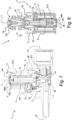
- Figure 7 shows, in a sectional view relative to a vertical plane, one possible embodiment of an electromagnetic valve 1 according to the present invention, comprising a tubular element 3 according to the present invention.
- a valve body 2 having at least one inlet 21, at least one outlet 23, and a connection tract 22, the latter hydraulically connecting said at least one inlet 21 to said at least one outlet 23.
- connection tract 22 comprises a seat 221, e.g. formed in its structure, in which a diaphragm element 14 is positioned.
- Said tubular element 3 according to the present invention is placed on top of said diaphragm element 14.
- Said diaphragm interacts with said sealing portion 42 of housing 4.
- Said tubular element 3 is removably connected, in particular screwed, to said valve body 2, thus ensuring hydraulic tightness, in particular in cooperation with said diaphragm element 14.
- said tubular element 3 comprises a housing 4 and a connection portion 5, wherein said housing 4 has a body 40 which is distinct from and independent of body 50 of connection portion 5.
- Said connection portion 5 is removably fastened to valve body 2 when tubular element 3 is assembled to said valve body 2.
- body 40 of housing 4 comprises: a cylindrical portion 41 having a closed distal end and an open proximal end; and a sealing portion 42, which acts upon diaphragm element 14.
- Said housing 4 internally houses a core 12, which is adapted to slide within said cylindrical portion 41. Said core 12 cooperates with said diaphragm element 14 to selectively allow a flow of fluid between inlet 21 and outlet 23 of valve body 2.
- a coil 11 is arranged around tubular element 3, in particular around said cylindrical portion 41 of housing 4, which coil 11 can generate a magnetic field capable of selectively moving core 12.
- a locking system 44 which is shown to be in the second configuration, thus locking said coil 11 around cylindrical portion 41 of said housing 4.
- body 440 of locking system 44 is visible which, by interacting with said gripping element 441, has undergone a deformation that has increased its outside diameter "D". From this figure one can infer that outside diameter "D" of body 440 of locking system 44 is greater than outside diameter "d" of cylindrical portion 41 of housing 4.
- said electromagnetic valve 1 according to the present invention is a direct valve.
- Figure 8 shows, in a sectional view relative to a vertical plane, one possible embodiment of a direct electromagnetic valve 1 according to the present invention, which comprises a tubular element 3 according to the present invention.
- Figure 8 shows an electrovalve adapted to be placed in a device or a circuit, e.g. of a water softener, comprised, for example, in a household appliance.
- a device or a circuit e.g. of a water softener, comprised, for example, in a household appliance.
- a portion of valve body 2 having at least one inlet 21, at least one outlet 23, and a connection tract 22, the latter hydraulically connecting said at least one inlet 21 to said at least one outlet 23.
- Said connection tract 22 comprises a seat 221, e.g. formed in its structure, in which a shutter 16 is arranged.
- said tubular element 3 can be removably connected to a valve body 2 while ensuring hydraulic tightness.
- said tubular element 3 is adapted to fit into a seat comprised in valve body 2 (not shown).
- said tubular element 3 is made as one piece. Therefore, said connection portion 5 and said housing 4 are made as one piece. More in detail, said connection portion 5, having a body 50, is adapted to be removably fixed to valve body 2 when tubular element 3 is interlocked with said valve body 2.
- housing 4 having a body 40, comprises: a cylindrical portion 41 having a closed distal end 41A and an open proximal end; and a sealing portion 42.
- said housing 4 internally houses core 12, which is adapted to slide within said cylindrical portion 41.
- a coil 11 is arranged around tubular element 3, in particular around said cylindrical portion 41 of housing 4, and can generate a magnetic field capable of selectively moving core 12.
- a locking system 44 At distal end 41A of housing 4 there is a locking system 44, which is shown to be in the second configuration, thus locking said coil 11 around cylindrical portion 41 of said housing 4.
- body 440 of locking system 44 is visible which, by interacting with said gripping element 441, has undergone a deformation that has increased its outside diameter "D". In this figure one can see that the outside diameter "D" of body 440 of locking system 44 is greater than outside diameter "d" of cylindrical portion 41 of housing 4.
- said electromagnetic valve 2 may be either a normally open valve or a normally closed valve, whose features and principles of operation are per se known to those skilled in the art.
- tubular element 3 can be easily used, e.g. as a spare part, and assembled to existing electrovalves 1 as an alternative to prior-art tubular elements 3.
- the present invention permits reducing the costs incurred for manufacturing an electromagnetic valve 1, in that it is possible to test the proper operation of coil 11 and the movement of core 12 prior to definitively fixing said coil 11 to housing 4 by using a locking system 44 which is simple to produce, reliable and inexpensive, and which allows coil 11 to be easily assembled to housing 4.
Landscapes
- Engineering & Computer Science (AREA)
- General Engineering & Computer Science (AREA)
- Physics & Mathematics (AREA)
- Electromagnetism (AREA)
- Mechanical Engineering (AREA)
- Power Engineering (AREA)
- Magnetically Actuated Valves (AREA)
- Superconductors And Manufacturing Methods Therefor (AREA)
- Massaging Devices (AREA)
Claims (12)
- Gehäuse (4) für elektromagnetische Ventile (1), das eingerichtet ist, im Inneren einen Kern (12) aufzunehmen und es ihm zu ermöglichen, darin zu gleiten, um das elektromagnetische Ventil (1) zu schalten;wobei mindestens ein Teil des Gehäuses (4) eingerichtet ist, von einer in dem elektromagnetischen Ventil (1) enthaltenen Spule (11) umgeben zu werden;wobei sich das Gehäuse (4) entlang einer Achse (L) erstreckt und ein distales Ende (41A) und ein offenes proximales Ende (41B) aufweist;wobei das Gehäuse (4) ein Verriegelungssystem (44) aufweist, das eingerichtet ist, die Spule (11) zu verriegeln;wobei das Gehäuse (4) dadurch gekennzeichnet ist, dass das Verriegelungssystem (44) in das Gehäuse (4) integriert ist und vorteilhafterweise am distalen Ende (41A) des Gehäuses (4) angeordnet ist;das Verriegelungssystem (44) eingerichtet ist, um anzunehmen:- eine erste Konfiguration, in der es ermöglicht, die Spule (11) um den mindestens einen Teil des Gehäuses (4) herum zu positionieren und von diesem zu entfernen;- eine zweite Konfiguration, die sich von der ersten Konfiguration unterscheidet, in der es die Spule (11) um den mindestens einen Teil des Gehäuses (4) verriegelt;wobei das Verriegelungssystem (44) in der ersten Konfiguration einen Außendurchmesser (D) mit einem bekannten Wert aufweist;wobei das Verriegelungssystem (44) in der zweiten Konfiguration einen Außendurchmesser (D) hat, der größer ist als der bekannte Wert;wobei das Verriegelungssystem (44) in der ersten Konfiguration den bekannten Außendurchmesser (D) beibehält, wenn die Spule (11) um das Gehäuse (4) herum positioniert wird und auch wenn die Spule (11) aus dem Gehäuse (4) entfernt wird; wobei das Gehäuse (4) dadurch gekennzeichnet ist, dass das Verriegelungssystem (44) so ausgelegt ist, dass es, sobald es die zweite Konfiguration angenommen hat, nicht wieder die erste Konfiguration annehmen kann.
- Gehäuse (4) nach Anspruch 1, wobei das Verriegelungssystem (44) einstückig mit dem Gehäuse (4) ausgebildet ist.
- Gehäuse (4) nach Anspruch 1 oder 2, wobei das Verriegelungssystem (44) und das Gehäuse (4) einen monolithischen Körper bilden.
- Gehäuse (4) nach einem der vorhergehenden Ansprüche, wobei das Gehäuse (4) aufweist:- einen zylindrischen Abschnitt (41) mit einem bekannten Außendurchmesser (d), der sich entlang der Achse (L) erstreckt und ein distales Ende (41A) und ein offenes proximales Ende (41B) aufweist;- einen Dichtungsabschnitt (42), der eingerichtet ist, mit einem in dem elektromagnetischen Ventil (1) enthaltenen Dichtungselement (14, 16) zusammenzuwirken, und der an dem offenen proximalen Ende (41B) des zylindrischen Abschnitts (41) angeordnet ist;wobei das Verriegelungssystem (44) einstückig mit dem zylindrischen Abschnitt (41) ausgebildet ist.
- Gehäuse (4) nach einem der vorhergehenden Ansprüche, wobei das Verriegelungssystem (44) aufweist:- mindestens einen Körper (440), der eine zylindrische Form aufweist;- mindestens einen ersten nachgiebigen Abschnitt (442), der eingerichtet ist, eine Bewegung des Körpers (440) entlang der Achse (L) zumindest beim Umschalten von der ersten Konfiguration zur zweiten Konfiguration des Verriegelungssystems (44) zu ermöglichen;- mindestens einen zweiten nachgiebigen Abschnitt (444), der eingerichtet ist, eine Vergrößerung des Außendurchmessers (D) des Verriegelungssystems (44) zu ermöglichen, sobald es die zweite Konfiguration angenommen hat.
- Gehäuse (4) nach Anspruch 5, wobei:- ein Greifelement (441) enthalten ist, das am distalen Ende (41A) des Gehäuses (4) angeordnet ist;- der erste nachgiebige Abschnitt (442) den Körper (440) mechanisch mit dem Greifelement (441) verbindet;- der zweite nachgiebige Abschnitt (444) in dem Körper (440) ausgebildet ist und eine Verformung des Körpers (440) ermöglicht, die seinen Außendurchmesser (D) vergrößert, wenn er mit dem Greifelement (441) zusammenwirkt.
- Gehäuse (4) nach einem der Ansprüche 1 und 6, wobei der erste nachgiebige Abschnitt (442) ein Bruchabschnitt ist.
- Rohrförmiges Element (3) für elektromagnetische Ventile (1), das eingerichtet ist, an einem Ventilkörper (2) montiert zu werden, der in einem elektromagnetischen Ventil (1) enthalten ist, aufweisend:- einen Verbindungsabschnitt (5), der eingerichtet ist, entfernbar an dem Ventilkörper (2) befestigt zu werden, um das rohrförmige Element (3) an dem Ventilkörper (2) zu montieren;- ein Gehäuse (4) nach einem der vorhergehenden Ansprüche.
- Rohrförmiges Element (3) nach Anspruch 8, wobei das Gehäuse (4) einen Körper (40) aufweist, der von dem Verbindungsabschnitt (5) getrennt und unabhängig ist, der seinerseits einen eigenen Körper (50) aufweist;
wobei der Körper (40) des Gehäuses (4) entfernbar mit dem Körper (50) des Verbindungsabschnitts (5) verbunden werden kann, wodurch eine Baugruppe gebildet wird. - Rohrförmiges Element (3) nach Anspruch 8, wobei das rohrförmige Element (3) monolithisch ist und aus einem Stück besteht.
- Elektromagnetisches Ventil (1) für Haushaltsgeräte, aufweisend:- einen Ventilkörper (2) mit: mindestens einem Einlass (21); mindestens einem Auslass (23); und einem Verbindungstrakt (22), der eingerichtet ist, den Einlass (21) mit dem mindestens einen Auslass (23) hydraulisch zu verbinden;- ein Dichtungselement (14, 16), das in einem Sitz (221) angeordnet ist, der in dem Verbindungstrakt (22) ausgebildet ist, und eingerichtet ist, selektiv einen Fluidstrom zwischen dem Einlass (21) und dem Auslass (23) des Ventilkörpers (2) zu ermöglichen;- ein rohrförmiges Element (3), das eingerichtet ist, mit dem Ventilkörper (2) entfernbar verbunden zu werden, und gleichzeitig hydraulische Dichtheit im Zusammenwirken mit dem Dichtungselement (14, 16) zu gewährleisten;- einen Kern (12), der eingerichtet ist, in dem rohrförmigen Element (3) zu gleiten, und mit dem Dichtungselement (14, 16) zusammenzuwirken, um selektiv einen Fluidstrom zwischen dem Einlass (21) und dem Auslass (23) des Ventilkörpers (2) zu ermöglichen;- eine Spule (11), die um das rohrförmige Element (3) herum angeordnet ist und ein Magnetfeld zum selektiven Bewegen des Kerns (12) erzeugen kann;dadurch gekennzeichnet, dass das rohrförmige Element (3) ein rohrförmiges Element (3) nach Anspruch 8 ist.
- Elektromagnetisches Ventil (1) nach Anspruch 11, wobei das elektromagnetische Ventil (1) entweder ein direktes Ventil oder ein indirektes Ventil ist.
Applications Claiming Priority (2)
| Application Number | Priority Date | Filing Date | Title |
|---|---|---|---|
| IT102021000025688A IT202100025688A1 (it) | 2021-10-07 | 2021-10-07 | Alloggiamento per valvole elettromagnetiche, elemento tubolare e relativa valvola elettromagnetica. |
| PCT/IB2022/059538 WO2023057941A1 (en) | 2021-10-07 | 2022-10-06 | Housing for electromagnetic valves, tubular element and related electromagnetic valve. |
Publications (2)
| Publication Number | Publication Date |
|---|---|
| EP4413285A1 EP4413285A1 (de) | 2024-08-14 |
| EP4413285B1 true EP4413285B1 (de) | 2025-02-19 |
Family
ID=79164606
Family Applications (1)
| Application Number | Title | Priority Date | Filing Date |
|---|---|---|---|
| EP22790067.7A Active EP4413285B1 (de) | 2021-10-07 | 2022-10-06 | Gehäuse für elektromagnetische ventile, rohrförmiges element und zugehöriges elektromagnetisches ventil |
Country Status (8)
| Country | Link |
|---|---|
| US (1) | US12435810B2 (de) |
| EP (1) | EP4413285B1 (de) |
| KR (1) | KR20240089330A (de) |
| CN (1) | CN118076824A (de) |
| IT (1) | IT202100025688A1 (de) |
| MX (1) | MX2024004081A (de) |
| PL (1) | PL4413285T3 (de) |
| WO (1) | WO2023057941A1 (de) |
Family Cites Families (10)
| Publication number | Priority date | Publication date | Assignee | Title |
|---|---|---|---|---|
| US3896405A (en) * | 1974-09-03 | 1975-07-22 | Emerson Electric Co | Solenoid valve with threaded core tube |
| FR2552582B3 (fr) * | 1983-09-27 | 1985-08-23 | Elbi Int Spa | Groupe de mise en action pour electrovannes, en particulier de machines a laver |
| GB2296075B (en) * | 1994-12-12 | 1998-08-05 | Elbi Int Spa | A support and guide unit for an obturator of a solenoid valve and a method for the manufacture thereof |
| US5941502A (en) * | 1996-10-31 | 1999-08-24 | Cooper; Robert J. | Electric valve assembly and method of making same |
| DE102010009400A1 (de) * | 2010-02-26 | 2011-09-01 | Schaeffler Technologies Gmbh & Co. Kg | Elektromagnetisches Hydraulikventil |
| JP5925504B2 (ja) * | 2012-02-03 | 2016-05-25 | 日立オートモティブシステムズ株式会社 | 電磁弁 |
| JP6248439B2 (ja) * | 2013-07-10 | 2017-12-20 | オムロンヘルスケア株式会社 | 電磁弁およびそれを備えた電子血圧計 |
| US9181730B1 (en) * | 2014-12-18 | 2015-11-10 | Fu-Chang Peng | Driving structure of electronic lock |
| JP6668726B2 (ja) * | 2015-12-10 | 2020-03-18 | 株式会社デンソー | 電磁弁 |
| US10874247B2 (en) * | 2018-06-29 | 2020-12-29 | Rockwell Collins, Inc. | Solenoid valve for aircraft galley brewing apparatus |
-
2021
- 2021-10-07 IT IT102021000025688A patent/IT202100025688A1/it unknown
-
2022
- 2022-10-06 CN CN202280067704.3A patent/CN118076824A/zh active Pending
- 2022-10-06 KR KR1020247014911A patent/KR20240089330A/ko active Pending
- 2022-10-06 MX MX2024004081A patent/MX2024004081A/es unknown
- 2022-10-06 US US18/699,254 patent/US12435810B2/en active Active
- 2022-10-06 PL PL22790067.7T patent/PL4413285T3/pl unknown
- 2022-10-06 EP EP22790067.7A patent/EP4413285B1/de active Active
- 2022-10-06 WO PCT/IB2022/059538 patent/WO2023057941A1/en not_active Ceased
Also Published As
| Publication number | Publication date |
|---|---|
| WO2023057941A1 (en) | 2023-04-13 |
| MX2024004081A (es) | 2024-07-19 |
| CN118076824A (zh) | 2024-05-24 |
| KR20240089330A (ko) | 2024-06-20 |
| IT202100025688A1 (it) | 2023-04-07 |
| PL4413285T3 (pl) | 2025-04-14 |
| US20240410487A1 (en) | 2024-12-12 |
| EP4413285A1 (de) | 2024-08-14 |
| US12435810B2 (en) | 2025-10-07 |
Similar Documents
| Publication | Publication Date | Title |
|---|---|---|
| TWI812998B (zh) | 閥 | |
| EP2387678B1 (de) | Ventil mit einem durch ein joch an einem kolbenrohr befestigten elektromagneten | |
| EP2504056B1 (de) | Männlicher luer verbinder mit ventil | |
| EP4413285B1 (de) | Gehäuse für elektromagnetische ventile, rohrförmiges element und zugehöriges elektromagnetisches ventil | |
| WO2015116319A1 (en) | Fastener for securing a panel on a support | |
| MXPA97008353A (en) | Electrical valve assembly and method of doing | |
| WO2011160746A1 (en) | Device for fastening a component to a fastening stud | |
| WO2000068607A1 (en) | Connector assembly and method of manufacture | |
| EP3781826B1 (de) | Befestigungsvorrichtung mit einem basisteil und einem sperrteil | |
| US20210156491A1 (en) | Pilot-type solenoid valve | |
| US10704700B2 (en) | Check valve structure | |
| KR101888774B1 (ko) | 연료 인젝터를 위한 필터 조립체, 연료 인젝터, 및 필터 조립체를 조립하는 방법 | |
| US12331774B2 (en) | Coupling bolt of a plug-in coupling, first component with the coupling bolt, associated plug-in coupling and connecting structure of two components | |
| US20110127147A1 (en) | Device for monitoring the state of a safety device on a machine | |
| EP4413286B1 (de) | Rohrförmiges element für elektromagnetische ventile und zugehöriges elektromagnetisches ventil | |
| KR101331932B1 (ko) | 급수용 밸브 조립체 | |
| KR20170066649A (ko) | 교번하는 시트 시스템을 가진 아마튜어 | |
| MXPA97000248A (en) | Procedure for the cross coupling of one piece at least locally cylindrical in a tubular piece, a suitable tool to carry out that procedure, and a set of two pieces coupled in cross according to e | |
| JP2001263527A (ja) | パイロット式電磁弁 | |
| US11788641B1 (en) | Combination structure of electronic water valve | |
| WO2018089614A1 (en) | Solenoid valve assembly with pilot pressure control | |
| EP0961897B1 (de) | Verfahren und apparat zum befestigen einer versorgungsleitung an einem elektromagnetventil | |
| CN223938803U (zh) | 一种电子龙头 | |
| CN217678191U (zh) | 引入到顶盖供给洗衣机的液体分配系统中的装置 | |
| WO2005070247A2 (en) | Swivel tack button, particularly for items of clothing such as jeans or the like, with very simple assembly and application |
Legal Events
| Date | Code | Title | Description |
|---|---|---|---|
| STAA | Information on the status of an ep patent application or granted ep patent |
Free format text: STATUS: UNKNOWN |
|
| STAA | Information on the status of an ep patent application or granted ep patent |
Free format text: STATUS: THE INTERNATIONAL PUBLICATION HAS BEEN MADE |
|
| PUAI | Public reference made under article 153(3) epc to a published international application that has entered the european phase |
Free format text: ORIGINAL CODE: 0009012 |
|
| STAA | Information on the status of an ep patent application or granted ep patent |
Free format text: STATUS: REQUEST FOR EXAMINATION WAS MADE |
|
| 17P | Request for examination filed |
Effective date: 20240503 |
|
| AK | Designated contracting states |
Kind code of ref document: A1 Designated state(s): AL AT BE BG CH CY CZ DE DK EE ES FI FR GB GR HR HU IE IS IT LI LT LU LV MC ME MK MT NL NO PL PT RO RS SE SI SK SM TR |
|
| GRAP | Despatch of communication of intention to grant a patent |
Free format text: ORIGINAL CODE: EPIDOSNIGR1 |
|
| STAA | Information on the status of an ep patent application or granted ep patent |
Free format text: STATUS: GRANT OF PATENT IS INTENDED |
|
| P01 | Opt-out of the competence of the unified patent court (upc) registered |
Free format text: CASE NUMBER: APP_52075/2024 Effective date: 20240917 |
|
| DAV | Request for validation of the european patent (deleted) | ||
| DAX | Request for extension of the european patent (deleted) | ||
| INTG | Intention to grant announced |
Effective date: 20241010 |
|
| GRAS | Grant fee paid |
Free format text: ORIGINAL CODE: EPIDOSNIGR3 |
|
| GRAA | (expected) grant |
Free format text: ORIGINAL CODE: 0009210 |
|
| STAA | Information on the status of an ep patent application or granted ep patent |
Free format text: STATUS: THE PATENT HAS BEEN GRANTED |
|
| AK | Designated contracting states |
Kind code of ref document: B1 Designated state(s): AL AT BE BG CH CY CZ DE DK EE ES FI FR GB GR HR HU IE IS IT LI LT LU LV MC ME MK MT NL NO PL PT RO RS SE SI SK SM TR |
|
| REG | Reference to a national code |
Ref country code: GB Ref legal event code: FG4D |
|
| REG | Reference to a national code |
Ref country code: CH Ref legal event code: EP |
|
| REG | Reference to a national code |
Ref country code: DE Ref legal event code: R096 Ref document number: 602022010927 Country of ref document: DE |
|
| REG | Reference to a national code |
Ref country code: IE Ref legal event code: FG4D |
|
| REG | Reference to a national code |
Ref country code: NL Ref legal event code: MP Effective date: 20250219 |
|
| PG25 | Lapsed in a contracting state [announced via postgrant information from national office to epo] |
Ref country code: RS Free format text: LAPSE BECAUSE OF FAILURE TO SUBMIT A TRANSLATION OF THE DESCRIPTION OR TO PAY THE FEE WITHIN THE PRESCRIBED TIME-LIMIT Effective date: 20250519 |
|
| PG25 | Lapsed in a contracting state [announced via postgrant information from national office to epo] |
Ref country code: FI Free format text: LAPSE BECAUSE OF FAILURE TO SUBMIT A TRANSLATION OF THE DESCRIPTION OR TO PAY THE FEE WITHIN THE PRESCRIBED TIME-LIMIT Effective date: 20250219 |
|
| PGFP | Annual fee paid to national office [announced via postgrant information from national office to epo] |
Ref country code: PL Payment date: 20250616 Year of fee payment: 4 |
|
| PG25 | Lapsed in a contracting state [announced via postgrant information from national office to epo] |
Ref country code: ES Free format text: LAPSE BECAUSE OF FAILURE TO SUBMIT A TRANSLATION OF THE DESCRIPTION OR TO PAY THE FEE WITHIN THE PRESCRIBED TIME-LIMIT Effective date: 20250219 |
|
| REG | Reference to a national code |
Ref country code: LT Ref legal event code: MG9D |
|
| PG25 | Lapsed in a contracting state [announced via postgrant information from national office to epo] |
Ref country code: IS Free format text: LAPSE BECAUSE OF FAILURE TO SUBMIT A TRANSLATION OF THE DESCRIPTION OR TO PAY THE FEE WITHIN THE PRESCRIBED TIME-LIMIT Effective date: 20250619 Ref country code: NO Free format text: LAPSE BECAUSE OF FAILURE TO SUBMIT A TRANSLATION OF THE DESCRIPTION OR TO PAY THE FEE WITHIN THE PRESCRIBED TIME-LIMIT Effective date: 20250519 |
|
| PG25 | Lapsed in a contracting state [announced via postgrant information from national office to epo] |
Ref country code: NL Free format text: LAPSE BECAUSE OF FAILURE TO SUBMIT A TRANSLATION OF THE DESCRIPTION OR TO PAY THE FEE WITHIN THE PRESCRIBED TIME-LIMIT Effective date: 20250219 |
|
| PG25 | Lapsed in a contracting state [announced via postgrant information from national office to epo] |
Ref country code: HR Free format text: LAPSE BECAUSE OF FAILURE TO SUBMIT A TRANSLATION OF THE DESCRIPTION OR TO PAY THE FEE WITHIN THE PRESCRIBED TIME-LIMIT Effective date: 20250219 |
|
| PG25 | Lapsed in a contracting state [announced via postgrant information from national office to epo] |
Ref country code: LV Free format text: LAPSE BECAUSE OF FAILURE TO SUBMIT A TRANSLATION OF THE DESCRIPTION OR TO PAY THE FEE WITHIN THE PRESCRIBED TIME-LIMIT Effective date: 20250219 Ref country code: PT Free format text: LAPSE BECAUSE OF FAILURE TO SUBMIT A TRANSLATION OF THE DESCRIPTION OR TO PAY THE FEE WITHIN THE PRESCRIBED TIME-LIMIT Effective date: 20250620 |
|
| PG25 | Lapsed in a contracting state [announced via postgrant information from national office to epo] |
Ref country code: BG Free format text: LAPSE BECAUSE OF FAILURE TO SUBMIT A TRANSLATION OF THE DESCRIPTION OR TO PAY THE FEE WITHIN THE PRESCRIBED TIME-LIMIT Effective date: 20250219 Ref country code: GR Free format text: LAPSE BECAUSE OF FAILURE TO SUBMIT A TRANSLATION OF THE DESCRIPTION OR TO PAY THE FEE WITHIN THE PRESCRIBED TIME-LIMIT Effective date: 20250520 |
|
| PGFP | Annual fee paid to national office [announced via postgrant information from national office to epo] |
Ref country code: TR Payment date: 20250617 Year of fee payment: 4 |
|
| PG25 | Lapsed in a contracting state [announced via postgrant information from national office to epo] |
Ref country code: SE Free format text: LAPSE BECAUSE OF FAILURE TO SUBMIT A TRANSLATION OF THE DESCRIPTION OR TO PAY THE FEE WITHIN THE PRESCRIBED TIME-LIMIT Effective date: 20250219 |
|
| PG25 | Lapsed in a contracting state [announced via postgrant information from national office to epo] |
Ref country code: SM Free format text: LAPSE BECAUSE OF FAILURE TO SUBMIT A TRANSLATION OF THE DESCRIPTION OR TO PAY THE FEE WITHIN THE PRESCRIBED TIME-LIMIT Effective date: 20250219 |
|
| PG25 | Lapsed in a contracting state [announced via postgrant information from national office to epo] |
Ref country code: DK Free format text: LAPSE BECAUSE OF FAILURE TO SUBMIT A TRANSLATION OF THE DESCRIPTION OR TO PAY THE FEE WITHIN THE PRESCRIBED TIME-LIMIT Effective date: 20250219 |
|
| PG25 | Lapsed in a contracting state [announced via postgrant information from national office to epo] |
Ref country code: IT Free format text: LAPSE BECAUSE OF FAILURE TO SUBMIT A TRANSLATION OF THE DESCRIPTION OR TO PAY THE FEE WITHIN THE PRESCRIBED TIME-LIMIT Effective date: 20250219 |
|
| PG25 | Lapsed in a contracting state [announced via postgrant information from national office to epo] |
Ref country code: AT Free format text: LAPSE BECAUSE OF FAILURE TO SUBMIT A TRANSLATION OF THE DESCRIPTION OR TO PAY THE FEE WITHIN THE PRESCRIBED TIME-LIMIT Effective date: 20250219 |
|
| PG25 | Lapsed in a contracting state [announced via postgrant information from national office to epo] |
Ref country code: CZ Free format text: LAPSE BECAUSE OF FAILURE TO SUBMIT A TRANSLATION OF THE DESCRIPTION OR TO PAY THE FEE WITHIN THE PRESCRIBED TIME-LIMIT Effective date: 20250219 Ref country code: EE Free format text: LAPSE BECAUSE OF FAILURE TO SUBMIT A TRANSLATION OF THE DESCRIPTION OR TO PAY THE FEE WITHIN THE PRESCRIBED TIME-LIMIT Effective date: 20250219 |
|
| PG25 | Lapsed in a contracting state [announced via postgrant information from national office to epo] |
Ref country code: RO Free format text: LAPSE BECAUSE OF FAILURE TO SUBMIT A TRANSLATION OF THE DESCRIPTION OR TO PAY THE FEE WITHIN THE PRESCRIBED TIME-LIMIT Effective date: 20250219 |
|
| PG25 | Lapsed in a contracting state [announced via postgrant information from national office to epo] |
Ref country code: SK Free format text: LAPSE BECAUSE OF FAILURE TO SUBMIT A TRANSLATION OF THE DESCRIPTION OR TO PAY THE FEE WITHIN THE PRESCRIBED TIME-LIMIT Effective date: 20250219 |
|
| REG | Reference to a national code |
Ref country code: DE Ref legal event code: R097 Ref document number: 602022010927 Country of ref document: DE |
|
| PLBE | No opposition filed within time limit |
Free format text: ORIGINAL CODE: 0009261 |
|
| STAA | Information on the status of an ep patent application or granted ep patent |
Free format text: STATUS: NO OPPOSITION FILED WITHIN TIME LIMIT |
|
| PGFP | Annual fee paid to national office [announced via postgrant information from national office to epo] |
Ref country code: DE Payment date: 20250630 Year of fee payment: 4 |
|
| 26N | No opposition filed |
Effective date: 20251120 |