EP4413239B1 - Verbrennungsturbine und wärmerückgewinnungssystemkombination mit scr-reaktoranordnung - Google Patents
Verbrennungsturbine und wärmerückgewinnungssystemkombination mit scr-reaktoranordnung Download PDFInfo
- Publication number
- EP4413239B1 EP4413239B1 EP22786920.3A EP22786920A EP4413239B1 EP 4413239 B1 EP4413239 B1 EP 4413239B1 EP 22786920 A EP22786920 A EP 22786920A EP 4413239 B1 EP4413239 B1 EP 4413239B1
- Authority
- EP
- European Patent Office
- Prior art keywords
- scr1
- hrsg
- scr2
- nox
- scr
- Prior art date
- Legal status (The legal status is an assumption and is not a legal conclusion. Google has not performed a legal analysis and makes no representation as to the accuracy of the status listed.)
- Active
Links
Images


Classifications
-
- F—MECHANICAL ENGINEERING; LIGHTING; HEATING; WEAPONS; BLASTING
- F01—MACHINES OR ENGINES IN GENERAL; ENGINE PLANTS IN GENERAL; STEAM ENGINES
- F01K—STEAM ENGINE PLANTS; STEAM ACCUMULATORS; ENGINE PLANTS NOT OTHERWISE PROVIDED FOR; ENGINES USING SPECIAL WORKING FLUIDS OR CYCLES
- F01K23/00—Plants characterised by more than one engine delivering power external to the plant, the engines being driven by different fluids
- F01K23/02—Plants characterised by more than one engine delivering power external to the plant, the engines being driven by different fluids the engine cycles being thermally coupled
- F01K23/06—Plants characterised by more than one engine delivering power external to the plant, the engines being driven by different fluids the engine cycles being thermally coupled combustion heat from one cycle heating the fluid in another cycle
- F01K23/10—Plants characterised by more than one engine delivering power external to the plant, the engines being driven by different fluids the engine cycles being thermally coupled combustion heat from one cycle heating the fluid in another cycle with exhaust fluid of one cycle heating the fluid in another cycle
-
- F—MECHANICAL ENGINEERING; LIGHTING; HEATING; WEAPONS; BLASTING
- F01—MACHINES OR ENGINES IN GENERAL; ENGINE PLANTS IN GENERAL; STEAM ENGINES
- F01N—GAS-FLOW SILENCERS OR EXHAUST APPARATUS FOR MACHINES OR ENGINES IN GENERAL; GAS-FLOW SILENCERS OR EXHAUST APPARATUS FOR INTERNAL-COMBUSTION ENGINES
- F01N3/00—Exhaust or silencing apparatus having means for purifying, rendering innocuous, or otherwise treating exhaust
- F01N3/08—Exhaust or silencing apparatus having means for purifying, rendering innocuous, or otherwise treating exhaust for rendering innocuous
- F01N3/10—Exhaust or silencing apparatus having means for purifying, rendering innocuous, or otherwise treating exhaust for rendering innocuous by thermal or catalytic conversion of noxious components of exhaust
- F01N3/18—Exhaust or silencing apparatus having means for purifying, rendering innocuous, or otherwise treating exhaust for rendering innocuous by thermal or catalytic conversion of noxious components of exhaust characterised by methods of operation; Control
- F01N3/20—Exhaust or silencing apparatus having means for purifying, rendering innocuous, or otherwise treating exhaust for rendering innocuous by thermal or catalytic conversion of noxious components of exhaust characterised by methods of operation; Control specially adapted for catalytic conversion
- F01N3/206—Adding periodically or continuously substances to exhaust gases for promoting purification, e.g. catalytic material in liquid form, NOx reducing agents
- F01N3/2066—Selective catalytic reduction [SCR]
-
- B—PERFORMING OPERATIONS; TRANSPORTING
- B01—PHYSICAL OR CHEMICAL PROCESSES OR APPARATUS IN GENERAL
- B01D—SEPARATION
- B01D53/00—Separation of gases or vapours; Recovering vapours of volatile solvents from gases; Chemical or biological purification of waste gases, e.g. engine exhaust gases, smoke, fumes, flue gases, aerosols
- B01D53/34—Chemical or biological purification of waste gases
- B01D53/92—Chemical or biological purification of waste gases of engine exhaust gases
- B01D53/94—Chemical or biological purification of waste gases of engine exhaust gases by catalytic processes
- B01D53/9404—Removing only nitrogen compounds
- B01D53/9409—Nitrogen oxides
- B01D53/9413—Processes characterised by a specific catalyst
- B01D53/9418—Processes characterised by a specific catalyst for removing nitrogen oxides by selective catalytic reduction [SCR] using a reducing agent in a lean exhaust gas
-
- B—PERFORMING OPERATIONS; TRANSPORTING
- B01—PHYSICAL OR CHEMICAL PROCESSES OR APPARATUS IN GENERAL
- B01D—SEPARATION
- B01D53/00—Separation of gases or vapours; Recovering vapours of volatile solvents from gases; Chemical or biological purification of waste gases, e.g. engine exhaust gases, smoke, fumes, flue gases, aerosols
- B01D53/34—Chemical or biological purification of waste gases
- B01D53/92—Chemical or biological purification of waste gases of engine exhaust gases
- B01D53/94—Chemical or biological purification of waste gases of engine exhaust gases by catalytic processes
- B01D53/9404—Removing only nitrogen compounds
- B01D53/9436—Ammonia
-
- F—MECHANICAL ENGINEERING; LIGHTING; HEATING; WEAPONS; BLASTING
- F01—MACHINES OR ENGINES IN GENERAL; ENGINE PLANTS IN GENERAL; STEAM ENGINES
- F01N—GAS-FLOW SILENCERS OR EXHAUST APPARATUS FOR MACHINES OR ENGINES IN GENERAL; GAS-FLOW SILENCERS OR EXHAUST APPARATUS FOR INTERNAL-COMBUSTION ENGINES
- F01N2370/00—Selection of materials for exhaust purification
- F01N2370/02—Selection of materials for exhaust purification used in catalytic reactors
-
- F—MECHANICAL ENGINEERING; LIGHTING; HEATING; WEAPONS; BLASTING
- F01—MACHINES OR ENGINES IN GENERAL; ENGINE PLANTS IN GENERAL; STEAM ENGINES
- F01N—GAS-FLOW SILENCERS OR EXHAUST APPARATUS FOR MACHINES OR ENGINES IN GENERAL; GAS-FLOW SILENCERS OR EXHAUST APPARATUS FOR INTERNAL-COMBUSTION ENGINES
- F01N2570/00—Exhaust treating apparatus eliminating, absorbing or adsorbing specific elements or compounds
- F01N2570/14—Nitrogen oxides
-
- F—MECHANICAL ENGINEERING; LIGHTING; HEATING; WEAPONS; BLASTING
- F01—MACHINES OR ENGINES IN GENERAL; ENGINE PLANTS IN GENERAL; STEAM ENGINES
- F01N—GAS-FLOW SILENCERS OR EXHAUST APPARATUS FOR MACHINES OR ENGINES IN GENERAL; GAS-FLOW SILENCERS OR EXHAUST APPARATUS FOR INTERNAL-COMBUSTION ENGINES
- F01N2610/00—Adding substances to exhaust gases
- F01N2610/02—Adding substances to exhaust gases the substance being ammonia or urea
-
- Y—GENERAL TAGGING OF NEW TECHNOLOGICAL DEVELOPMENTS; GENERAL TAGGING OF CROSS-SECTIONAL TECHNOLOGIES SPANNING OVER SEVERAL SECTIONS OF THE IPC; TECHNICAL SUBJECTS COVERED BY FORMER USPC CROSS-REFERENCE ART COLLECTIONS [XRACs] AND DIGESTS
- Y02—TECHNOLOGIES OR APPLICATIONS FOR MITIGATION OR ADAPTATION AGAINST CLIMATE CHANGE
- Y02E—REDUCTION OF GREENHOUSE GAS [GHG] EMISSIONS, RELATED TO ENERGY GENERATION, TRANSMISSION OR DISTRIBUTION
- Y02E20/00—Combustion technologies with mitigation potential
- Y02E20/16—Combined cycle power plant [CCPP], or combined cycle gas turbine [CCGT]
Definitions
- the inventive subject matter is inclusive of a combination combustion turbine power generating apparatus and heat recovery system, as in a heat recovery steam generator ("HRSG"), wherein the exhaust of the combustion turbine, that is travelling through the heat recovery system (e.g., HRSG), is treated by an emission reduction system that comprises a reducing reagent (as in ammonia) feed and a receiving SCR reactor assembly.
- HRSG heat recovery steam generator
- the invention further relates to the emission reduction system specially designed for use in the combination combustion turbine power generating apparatus and heat recovery system, and methods of using and assembling each.
- T-H combination a combination of a combustion (gas driven) turbine generator apparatus and a heat recovery system
- a T-H combination features a combustion turbine engine that typically operates by drawing air into a compressor to increase the gas pressure.
- a fuel often a hydrocarbon fuel such as natural gas, is combusted using the compressed air. This combustion often takes place under relatively “lean” conditions, where more than the stoichiometric amount of oxygen necessary for complete combustion of the hydrocarbon fuel components is used. This helps to maintain a relatively low combustion temperature, which can improve the durability of materials used to make the turbines.
- the high temperature, high pressure gas from a combustor is fed into a gas turbine engine where the gas expands and the temperature of the gas drops.
- the gas turbine drives the compressor, as well as a generator that generates electric power.
- the exhaust gas leaving the turbine is at a relatively high temperature and can be used in a heat recovery system such as a heat recovery steam generator ("HRSG") before being exhausted or treated in downstream or integrated operations to reduce unwanted emissions.
- HRSG heat recovery steam generator
- the steam created by the heat recovery steam generator can be used as part of a combined cycle plant to drive a steam turbine. This increases the power generation efficiency of a power plant using the HRSG.
- the exhaust gas contains pollutants; such as, when utilizing hydrocarbon based fuels, hydrocarbons (HC), carbon monoxide (CO), volatile organic compounds (VOC) and oxides of nitrogen (NOx), all of which are being controlled by various regulatory agencies.
- pollutants such as, when utilizing hydrocarbon based fuels, hydrocarbons (HC), carbon monoxide (CO), volatile organic compounds (VOC) and oxides of nitrogen (NOx), all of which are being controlled by various regulatory agencies.
- NOx generation can be particularly problematic relative to some fuels, such as direct hydrogen and ammonia based fuels, that have high NOx output upon combustion.
- the avoidance of having to use a prior art separate body OC reactor(s) as well as separate body ASC reactor(s) enables the addition, under the present invention, of the second SCR reactor within a similar volume region of the heat recovery system (that would otherwise have been occupied by that OC and/or ASC reactor body) while retaining desired pressure drop levels (e.g., preferably avoiding, under examples of the present invention, a pressure drop of more than 3.5 inches water column from the inlet to outlet of the HRSG, as in a preferred pressure drop maintenance range of 0.054 to 0.126 psi (1.5 to 3.5 inches water column).
- desired pressure drop levels e.g., preferably avoiding, under examples of the present invention, a pressure drop of more than 3.5 inches water column from the inlet to outlet of the HRSG, as in a preferred pressure drop maintenance range of 0.054 to 0.126 psi (1.5 to 3.5 inches water column).
- an arrangement of the present invention features an emission reduction system (ERS) having a reducing reagent supply source as in a reducing reagent injector system (RRI1).
- the RRI1 is represented by an ammonia supply source ((e.g., an ammonia injection grid) generally referenced as "AIG1" going forward) to feed ammonia (e.g., anhydrous ammonia, aqueous ammonia, urea (as in aqueous urea solutions) or other ammonia supply means) into the turbine exhaust gas with its NOx, such that the NH3/NOx mix comes into contact with the catalyst assembly having, in exhaust flow sequence, a first SCR reactor (SCR1), a turbulence generator ("TG" -- as in a static mixer "SM”), and a second SCR reactor (SCR2).
- SCR1 first SCR reactor
- TG turbulence generator
- SCR2 second SCR reactor
- a second reducing reagent supply source such as a second reducing reagent supply injection location (RRI2), as in a second ammonia injection location (referenced as "AIG2" preferably in place of the TG (SM) in the earlier described embodiment.
- RRI2 second reducing reagent supply injection location
- AIG2 ammonia injection location
- integrated turbulence generating means and RRI means such as turbulence generating mixers positioned for redirecting outflow of reducing agent exiting from (and preferably also supported by) injectors/piping of the RRI.
- An additional advantage that has resulted from the present invention arrangements is that there is less of need for high resolution and even intermediate resolution reducing reagent supply units. That is, with reference to an ammonia supply as an example of the reducing reagent supply, a low resolution AIG is one with fewer tunable zones and lower required resolution (and hence an RRI with less initial assembly and maintenance costs).
- a typical conventional high resolution AIG (suited for the above described HRSGs) can have more than 24 independently controlled zones, as in an AIG with 3 vertical columns of zones and 9 rows of horizontal zones for 27 separate tunable zones (with or without added integrated injection mixers, and with or without multiple generally Y-axis separated injection locations upstream of a common SCR).
- Alternative conventional high resolution AIG examples feature more than 18 tunable zones as in 21 or more zones (3 vertical columns of zones with 7 horizontal zones resulting in 21 separate tunable zones) plus added integrated mixers supported by the injection system and used to disrupt (add turbulence) to the injection reducing reagent flow, with such added piping mixers being illustrated by US 8,017,084 B1 to Wirt et al .
- a low resolution AIG suited for use under many embodiments of the present invention features less than the above noted 21 separate tunable zones, and preferably at or less than 18 tunable zones free of separate Y-axis injection locations and/or free of integrated piping mixers, as in RRI units (e.g., AIG unit) that function with, for instance, a higher ammonia to NOx mal-distribution, as in those functioning with a mal-distribution higher than 10% RMS.
- RRI units e.g., AIG unit
- An RRI (e.g., AIG) with 6 to 18 total tunable reducing reagent zones, more preferably 10 to 16, as in 12 or 16 total tunable zones and free of integrated piping supported mixers (and preferably also free of Y-axis separation) are examples of low resolution RRI units.
- low resolution RRIs are preferably free of added integrated piping supported mixers and also are preferably limited to one general Y-axis insertion location (preferably only on one side or limited to opposite side insertions with a central common supporting frame structure).
- low resolution RRI units include those with 3 or less (e.g. preferably less than 3 as in only 1 or 2) vertical column(s) of zones (as in an AIG with 16 independently tunable horizontal zones presented in one vertical column).
- RRI configurations representing low resolution RRI units can be utilized, as in those comprised of any XxZ combination that provides the desired "low resolution" total zones (e.g., 3 vertical x 4 horizontal for 12 total tunable zones or 2 vertical x 8 horizontal for a total of 16 total tunable zones).
- RRI1 and RRI2 are provided with added flow disruption integrated piping mixers such as that described above (as in adding integrated piping supported mixer plating such as that described in US 8,017,084 B1 above) to the injector pipes in RRI2 in place of an SM insertion or together with the SM insertion).
- integrated piping supported mixer plating such as that described in US 8,017,084 B1 above
- RRI e.g., AIG
- suitable RRI reducing agent supply means include those falling within the intermediate resolution category, which preferably feature more than 18 and 24 or less tunable zones, and which are, like the low resolution category, free of added integrated piping supported mixers and preferably also free of additional Y-axis spaced reducing agent injection systems leading to a common SCR.
- intermediate resolution RRIs are also preferably arranged generally with just a single Y-axis injection location.
- RRIs with zones of between 21 and 24 zones and being free of any added piping assembly mixers, and also limited to one Y-axis general injection location are also representative of intermediate category RRIs under aspects of the present invention.
- the present invention is directed at providing a T-H combination that features a design directed at meeting the more stringent emission requirements, both with respect to NOx level reduction and ammonia slip output levels, as taken at the heat recovery system's (e.g., HRSG) outlet.
- the present invention is directed toward advanced NOx reduction (e.g., 96% NOx reduction or higher, including 97%, 98% and 99%) while retaining NH3 slip at or below 5ppm (as in at or less than 4, 3 or 2ppm NH3 slip).
- the present invention is thus directed at attaining high NOx removal with low slippage values even relative to systems with relatively high NOx generation levels (as in the noted larger natural gas driving turbine generators and systems featuring alternate fuels other than natural gas, that, upon combustion, have even higher NOx generation (e.g., > 60ppm NOx) at the turbine outlet).
- fuels such as hydrogen based fuels (e.g., direct hydrogen or indirect hydrogen as in through ammonia (including green ammonia) sourcing) are considered illustrative of fuels that can have a relatively higher NOx output, such as ⁇ 60 to ⁇ 100ppm NOx.
- This advanced NOx reduction with limited NH3 slip is achieved through an efficient emission reduction system ERS having an SCR catalyst assembly.
- FIG. 2A shows (schematically) an example of a compound/reducing reagent supply system 220 (also referenced as RRI); which, in an embodiment of the present inventions features a reducing reagent suitable for SCR reaction such as one that comprises aqueous ammonia, anhydrous ammonia, and/or aqueous urea.
- a reducing reagent suitable for SCR reaction such as one that comprises aqueous ammonia, anhydrous ammonia, and/or aqueous urea.
- ammonia is used as the reducing agent it may be made available by feeding an ammonia precursor compound, e.g., urea, ammonium carbamate, or ammonium formate, into the exhaust gas stream, and by subsequent hydrolysis.
- supply system 220 is a first in line component of an illustrative ERS embodiment of the presents invention.
- Supply system 220 preferably is an intermediate or low resolution RRI, preferably also with a single Y-axis injection location upstream of the first SCR1 (in alternate embodiments the noted single zone can be supplemented with a further upstream and/or downstream zone, although an ERS having the one only injection of reducing reagent zone upstream of SCR1 is preferred for many intended uses).
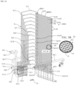
- Each of manifold segments MAI1 to MAI16 are further shown as providing support for a plurality of injection lances IJL, with each injection lance IJL extending in a widthwise direction within HRSG (X-axis) direction out from the supporting respective manifold segments and amongst MAN1 to MAN16, and with each injection lance within the respective four in number sets being respectively capped at the free ends by capping CP (that represent the supported ends of the injection lances at the opposite side wall of the HRSG which defines the containment space of containment structure CS, with the support being, for instance, open top pipe stubs attached to the HRSG interior side wall in which the capped manifold ends can nest with X-axis expansion room).
- the combination of the reagent supply piping and associated individual manifold regions (e.g. MAN1) as well as the ability to control the overall output of the IPs within each of the manifolds (16 manifolds shown in FIG. 3A ) is illustrative of presenting different tunable zone regions relative to the exhaust flow FL with each zone being individually and independently controllable as to no-flow or full flow (and more preferably a variable flow valve arrangement wherein there is the ability to choose percentage levels between 0% (no flow) and 100% (full available flow output) as in any percentage level such as 1%, 2%....98%, 99% relative to the open-close valve status of the controlled and adjustable valve for that particular line (and hence also for that particular manifold)).
- the nature of the system 220A is representative of a relatively easy piping assembly construction as compared to injection systems that are more complex such as those involving one or more of the following criteria (i) a high number of tunable zones (e.g., greater than 24), (ii) added mixing means to the piping, (iii) multiple Y-axis separated supply locations with each having its own independent tunable zones sets, and (iv) more than one side wall (or a combination of any two or more of side/top/bottom) piping insertion sites into the containment space, as in ones coming from both sides of the HRSG (and/or from a top-down location) coupled with at least one of (i), (ii) or (iii).
- FIG. 3A example can be considered an example of a "low resolution" RRI (AIG).
- AIG high resolution injection assemblies
- injection locations (often resulting in multiple Y-axis locations to provide room) or added pipe supported mixers with, for instance, more than 18 in the number of tunable zones) has the ability to achieve more universal mixing relative to the exhaust flowing thereby and thus a lower mal-distribution % potential (e.g., less areas where there is improper NH3/NOx mixing, and in those areas where there is an injection zone the output of the injection zone is designed with a suitable injection ratio for the passing exhaust based on the independent tunable nature of the injection).
- a lower mal-distribution % potential e.g., less areas where there is improper NH3/NOx mixing, and in those areas where there is an injection zone the output of the injection zone is designed with a suitable injection ratio for the passing exhaust based on the independent tunable nature of the injection).
- the arrangement of the present invention is well suited at providing a lowered need for reagent supply system complexity, while still providing an ERS that can achieve high NOx removal and low reagent (e.g., NH3) slippage as per the reduction levels described above and below under the present invention.
- the FIG. 3A and 3C supply systems 220A and 220B are examples of a low resolution and an intermediate resolution supply system, respectively, that avoids the above noted disadvantages of high cost in materials, assembly and maintenance relative to a high resolution RRI.
- FIGS. 3D to 3F show an example of a high resolution reagent supply system 220H having an injector assembly IAH having 21 tunable zones represented by 3 columns (CO1, CO2 and CO3) and 7 tunable zones at vertical locations V1 to V7 such that, not only can there be modified the injection flow in each of the seven vertical levels V1 to V7, but there also can be modified the independent tunable zones in the left, right and center via the independent columns of CO1, CO2 and CO3 across the X-axis.
- the RRI 220H has an injector assembly IAH with 21 independent injector conduits (with IJ1 feeding zone Z1 and IJ3 feeding zone Z3 being representative of 2 of the 21).
- RRI 220H is shown to have 21 independent zones which is in the intermediate zone number level, but due to the added inclusion of pipe mixers BF on each of the injection lances IL (with BF1L, BFL10 and BFR1 and BFR10 only depicted for convenience) there is a great deal of added complexity as to render RRI 220H a high resolution example.
- Pipe supported mixing means BF represents added plating that is placed on the upstream of the pipe (e.g., by welding) as to generate turbulence in the flow over the individual injection lances IL, whereupon the injection port feed of reducing reagent intermixes (with the FIG. 3D example feeding the reagent in a common flow direction of the exhaust).
- FIG. 3D further shows the high resolution RRI 220H in its support relationship in the space of containment structure CS represented by the interior surface of the HRSG featuring left side wall SWL, right side wall SWR, top wall TW and bottom wall BW.
- Z-axis frame structure struts STS supports to facilitate central suspension positioning of the entire RRI.
- the feed piping represented by bi-pass manifold IMA and the central manifold/support pipe post IPO are also provided with independent ports drilled therein as to avoid blind spot areas relative to the comprehensive RRI shown in FIG. 3D .
- suitable plating to cover the peripheral area of the 21 zone flow facing region as to preclude peripheral exhaust slip past the SCR reactor shown.
- a conventional sourcing system (not shown) can be used to supply the reagent to the injectors of the supply systems 220, 220A,220B and 220H, with a non-exclusive example of such a conventional sourcing system being found in US 6,550,250 B2 to Mikkelsen et al.
- Compound/reagent supply system 220 (or 220A or 220B - with 220 used below generically to represent each of 220, 220A and 220B (as well as 220H such as in a retrofit situation or wherein a high resolution RRI is deemed acceptable despite the added complexity and cost) absent a contrary indication) is designed to supply, in an upstream region of the ERS, a reagent compound suited for use under the present invention.
- 2A is thus representative of, for example, an ammonia supply zone that occupies a limited linear length region (e.g., the interior piping occupies some length of the HRSG limited length/volume to be afforded the ERS of the present invention- which is generally relatively minimal for 220 with its single Y-axis insertion location).
- the reducing reagent (e.g., NH3) provided by supply system 220 into exhaust gas E containing the NOx to be reduced is mixed and distributed to the concentration criteria for achieving a desired NH3/NOx ratio to achieve expected ERS performance.
- NH3 supply amount can be adjusted via a suitable controller (e.g., see controller CN in FIG.
- an aspect includes the compound/reagent supply system 220 being in communication with a controller such as controller CN (or a sub-component thereof if the controller CN is one that is also associated with general control of the T-H combination (e.g., a sub-control associated with ERS functioning)).
- controller CN can include non-transitory code or instructions stored in a machine-readable medium (e.g., memory) and used by a processor to implement the techniques disclosed herein.
- Controller CN can also be hard wired to any sensing means utilized or configured to operate solely or partially in wireless fashion with the sensing means (e.g., transmitting sensors and corresponding receiving units that provide data to the processing system (e.g., processor circuitry for carrying out the above described functioning)).
- a feature of the present invention includes the ability to loosen the level of rigidity associated with setting up the NH3/NOx mal-distribution value ahead of at least the SCR1 and preferably both the SCR1 and SCR2, and thus the controller can be set to provide and maintain that less strict mal-distribution Xsd.
- the present invention is inclusive of configuring and/or setting the controller to allow for, via RRI1 (e.g., an AIG1) supply, a mal-distribution value of greater than 10% and less than or equal to 20%, with a greater than 10 to 15% range being illustrative of a preferred range reaching SCR1, and a greater than 10 to 20% range being illustrative of a suitable range reaching SCR2, which ranges are well suited for handling of anticipated NOx reduction and minimized slip levels requirements such as those values for NOx reduction and ammonia slip being ⁇ 95% (including values of 96, 97, 98 and 99%) and ⁇ 5ppm, (including values of 4, 3, 2, 1 ppm), respectively.
- RRI1 e.g., an AIG1
- a mal-distribution value of greater than 10% and less than or equal to 20%
- a greater than 10 to 15% range being illustrative of a preferred range reaching SCR1
- a greater than 10 to 20% range being illust
- the ERS described above represents an efficient emission reduction system means (“or SCR Reactor") that is considered available for alternate uses.
- SCR Reactor an efficient emission reduction system means
- the SCR Reactor of the present invention (ERS or ERS') is designed to be particularly well suited for handling the NOx output of a turbine such as those described herein with exhaust being fed to a heat recovery system such as an HRSG.
- catalyst reactor assembly CRA (as part of the illustrated ERS) which in the FIG. 2A illustrated embodiment is downstream of supply system 220 and includes first and second selective catalytic reduction reactors (SCR1 and SCR2) referenced in FIG. 2A by 210A and 210B together with an intermediate turbulence generator (TG) as in a static mixer (SM) referenced in FIG. 2A by 230.
- SCR1 and SCR2 selective catalytic reduction reactors
- TG intermediate turbulence generator
- SM static mixer
- Embodiments under the invention are inclusive of having SCR1 and SCR2 being the same (as in entirely the same in configuration, SCR catalyst material, SCR substrate, and SCR frame structure) such that a universal approach can be taken when assembling the walls for SCR1 and SCR2.
- Alternate embodiments are inclusive of having SCR1 and SCR2 not exactly the same, although potentially having one or more of the remaining attributes in common, as in having a different catalyst material on SCR1 as compared to SCR2, but a common configuration.
- the SCR2 catalyst material can include materials that are different than that of SCR1.
- the SCR2 at a cooler location may include PGM material that is not present in SCR1 or a higher PGM load as compared to the upstream SCR1, as in Pd or more Pd in SCR2 as compared to SCR1 as to reduce the potential for PGM (e.g., Pd) volatility.
- SCR SCR1 and/or SCR2
- SCR1 and/or SCR2 can be either one that is single functioning (designed with a focus on NOx reduction) or multi-functional (such as a dual function SCR designed with a focus on NOx reduction as well as, for example, a secondary function as in an oxidizing catalyst (OC) of HC, CO and VOCs as well).
- OC oxidizing catalyst
- a triple functioning SCR or an alternate dual functioning are featured under the present invention.
- an added avoidance slip catalyst ASC PGM loading is further envisioned under aspects of the invention as in a third zone on a common substrate (e.g., an upstream OC zone without SCR material/ an intermediate SCR only zone and a downstream ASC zone); or relatively less or no-PGM SCR upstream/ASC alternate dual zone arrangement, or OC PGM/SCR no PGM alternate dual zone configuration.
- the first, second (and third or more when present) zones are preferably in the noted upstream to downstream listing sequence, although alternate embodiments include having alternate zone sequences if the requirements dictate.
- the SCR1 and/or SCR2 are stationary emission control catalysts such as those with monolithic catalyst bodies, as in corrugated or honeycomb monolithic catalytic bodies with encompassing structural framing to withstand stacking loads.
- the SCR1 and SCR2 are provided as independent wall formations, with each wall made up of (relative to the Y-axis length of the HRSG) a single metal containment structure or integrated (in the linear length) multi-containment unitary wall building block structures with respective SCR material per containment structure, with the former single containment structure arrangement being typically well suited even for the higher removal rates of NOx and low reduction reagent slippage amounts mentioned above.
- Suitable stationary emission control catalysts include Umicore AG's "DNX” type catalysts.
- Umicore's DNX ® catalysts are based on a corrugated fiber-reinforced titanium dioxide (TiO2) carrier plate. The plates are homogeneously impregnated with the active components, in that the entire ceramic plate is composed of a uniform distribution of tungsten trioxide (WO3) and vanadium pentoxide (V2O5).
- WO3 tungsten trioxide
- V2O5 vanadium pentoxide
- Table 1 An illustrative material composition table for the noted "DNX" type catalysts can be seen in Table 1 below.
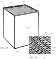
- FIGS. 9 and 10 further show gaps being defined between support struts (the star points extending out to a circular disc with gaps between the narrowing star point supports). As shown in FIG. 10 , the gaps afforded by the downstream extending projections off the downstream surface of plate wall PW leads to turbulent flow pattern generation FL in the downstream exhaust flow E D with, for example, contained ammonia and NOx being well intermingled before coming into contact with SCR2.
- FIGS. 11 and 11A there is illustrated an alternate embodiment of a turbulence generator TG in association with an SCR module 100.
- the TG is shown in FIGS. 11 and 11A as an integrated form of a static mixer SM (referenced as ISM for convenience).
- ISM is shown to be integrated with the downstream end of the SCR1 such that NOx and any bypassing ammonia is subject to the turbulence generator provided by ISM for each modular unit 100.
- static mixer 230 shown in FIG. 2A and FIG.
- the arrangement shown in FIG. 11 allows for a plurality of static mixers of the ISM type that are individually associated with respective modular units 100 such that there is a number of ISMs that are each supported by a respective modular unit and designed to cover the desired amount of the area represented by a cross-section of the CS (e.g., all of the modular units 100 in the SCR wall having an associated ISM, or only some of the modular units having an ISM in the wall as to cover regions of the SCR wall in most need of turbulence generation as in a periphery only ISM ring).
- the ISMs feature a plate PL having a plurality of partially covered apertures that act to redirect the flow though the main planar plate in which the aperture/caps are formed in similar fashion to the arranged shown in FIG. 9 and 10 for the earlier described static mixer.
- the individual plates of the ISM are secured directly to the framing 102 of the modular units 100 as by added bracketing BR that can be welded, bolted etc. to both the framing 102 at one end and to the plate PL of the ISM at the other. In this way, an integrated SCR wall component and static mixer is provided.
- the distance Dx helps in achieving a desired level of intermixing of both pass through NOx and ammonia as well as (particularly when the modular units defining the outer periphery of the SCR wall feature ISMs) bypass slippage of the exhaust components to be removed as in NOx and ammonia bypassing the SCR1 wall.
- FIG. 4A there can be seen (by dashed line demarcation) ERS comprised of RRI1 (with or without TGL) /SCR1/TG (SM represented)/SCR2 in sequence in the exhaust flow direction. There can also be seen (by dot-dash demarcation) catalyst reactor assembly CRA which features SCR1/TG (SM represented)/SCR2.
- FIG. 4A also illustrates the aforementioned controller CN which facilitates the above/below described operation of the T-H combination (shown schematically in wireless format for this embodiment, although hardwiring to the various sensors (not shown) described above/below or a mix of hardwired and wireless is also featured under the present invention).
- controller CN which facilitates the above/below described operation of the T-H combination (shown schematically in wireless format for this embodiment, although hardwiring to the various sensors (not shown) described above/below or a mix of hardwired and wireless is also featured under the present invention).
- the RRI1 can be an AIG1 and the TG an SM as in the independent SM shown in FIG. 9 or an SCR1-SM(ISM(s)) combination such as shown in FIG. 11 .
- AIG1 and AIG2 relative to potential options for RRI1 and RRI2 (but it is intended that the usage of AIG1 and AIG2 in the discussion to follow represent only examples as to RRI1 and RRI2 and that RRI1 and RRI2 can be switched out for the references AIG1 and AIG2 in the discussion below as when utilizing alternate reducing reagent sources).
- AIG1/SCR1/TG e.g. SM
- SCR2 SCR1-SM(ISM(s)
- any independent body OC as well as any independent body ASC within the CS of HRSG (as in between the inlet end of the HRSG to the outlet end of the HRSG (or at least within the ERS volume represented by length Lx in FIG. 4A )).
- Alternate embodiments of the present invention can include additions of OC and/or ASC independent catalyst bodies (e.g., an OC "wall" spaced upstream of the SCR1).
- the HRSG has to have a suitable length and volume to accommodate the exhaust output of the exhaust generation source such as a turbine associated with the T-H combination for which the ERS of the present invention acts to remove emissions.
- the exhaust generation source such as a turbine associated with the T-H combination for which the ERS of the present invention acts to remove emissions.
- the ERS needs to function efficiently within the noted linear length to achieve the described NOx reduction and ammonia slip avoidance levels under the present invention.
- FIG. 4A shows an ERS well suited for use with such larger turbine-generator combinations, and has dimensions well suited for working within a linear length of an HRSG, as represented by the ERS linear length Lx in FIG. 4A (which is represented by, for example, a length of 6.096 to 7.3152 meters (20 to 24 feet) positioned within the aforementioned LxWxH dimensions described above for HRSG that are suitable for use with the described "larger" turbine-generator combinations; or, alternatively, the region of the ERS within the linear length of the HRSG can be provided in an enlarged or bulging WxH region along the length of the HRSG to allow for good ERS flow surface contact without an overall WxH increase for the full linear length of the HRSG).
- the total linear length occupation for the ERS is represented by Lx (extending from the most upstream point of AIG1 to the most downstream point of SCR2) which in preferred embodiments (e.g., those suited for the "larger" turbine-generator combinations) is in the noted 6.096 to 7.3152 meters (20 to 24 feet) range (with 6.096 to 6.7056 meters (20 to 22 feet) being more preferred for many HRSG set ups).
- the Table 2 below shows some preferred relative spacing of AIG1, SCR1, SM (or TG), SCR2 that is designed to be well suited for removing higher percentages of NOx (e.g., at or greater than 95% as in 97%, 98% and 99% being illustrative of higher percentage rates for NOx removal) while retaining reagent (e.g., ammonia) slip levels downstream of the outlet of SCR2 at or less than 3 ppm NH3 (more preferably less than or equal to 2 ppm NH3).
- reagent e.g., ammonia
- Value Lo in the dimension ranges noted in Table 3 below represents the distance from an inlet plane (after the expansion phase of ducting between the turbine output and CS of HRSG) to a linear midpoint of AIG1;
- L 1 is representative of the linear distance from the midpoint of AIG1 to midpoint of SCR1;
- L 2 is representative of the linear distance from the midpoint of SCR1 to linear midpoint of SM;
- L 3 is representative of the linear distance from the midpoint of SM to midpoint of SCR2.
- Various other dimensional relationships are thus also represented as in the distance between the midpoint of SCR1 to midpoint of SCR2 as L 2 + L 3 .
- dimension Ly is representative of the total linear length for the output exhaust from the downstream side of SCR1 (as well as any slippage past the periphery of SCR1) till reaching the upstream surface of SCR2 which is an area where the turbulence generator means is active in intermixing the NH3 and NOx within the Ly volume.
- Lz is representative of the distance from the downstream surface of SCR1 to the upstream end of SM which is a value designed to achieve a desired level of intermixing relative to the NH3/NOx ratio (as in placement of the midpoint of SM within the first 25% of the length Ly, and more preferably in a range of 0% to 20% (with 0% representing a flush attachment of SM to the downstream surface of SCR1).
- bracketing can be utilized to achieve an integrated SCR/SM inclusive of ones having a spacing Lz range of 12.7 to 203.2 mm (0.5 inch to 8 inches) and more preferably 25.4 mm to 152.4 mm (1 inch to 6 inches).
- TG e.g., SM
- SM e.g., SM
- This placement of the TG(SM) can include a placement within 1.219 meters (4 feet) of the outlet end of the SCR1, preferably within 0.609 meters (2 feet) inclusive of the noted FIG. 11 configuration wherein a close spacing of from 1 inch to 6 inches is made available.
- An embodiment of the present invention is directed at assembling the emission reduction system ERS within a T-H combination, and more specifically within the HRSG of a T-H combination (e.g., accessing CS of HRSG, as during initial assembly or during a retrofit operation of a preexisting catalyst system in an HRSG).
- the assembly operation includes positioning each of SCR1/TG (e.g., SM)/SCR2 of CRA within HRSG (as well as AIG1, as in either a refurbish if a pre-existing ammonia sourcing structure is insufficient or in an initial installation in a new T-H combination). While the structural sequence in an upstream to downstream exhaust flow direction is AIG1/SCR1/TG (e.g.
- the assembly sequence can be the same as the above noted sequence relative to exhaust flow passage or an alternative one as inserting each of SCR1 and SCR2 and then SM (or SM can be attached to SCR1 and/or TGL to AIG1 and the combination inserted together).
- AIG1/SCR1/TG e.g., SM
- SCR2 are fixed in position within HRSG; and, in some embodiments, added sealing material can be provided between the exterior periphery of any component of CRA that is in need of added sealing as in sealing about SCR1 and/or SCR2 to avoid exhaust bypass; as in ceramic fiber seals being pre-attached or worked in after placement of the SCR1 or SCR2 being provided with added sealing and/or the addition of blocking "seal-off" plating to block access to openings about the SCR1 and/or SCR2 periphery(ies).
- ceramic fiber seals being pre-attached or worked in after placement of the SCR1 or SCR2 being provided with added sealing and/or the addition of blocking "seal-off" plating to block access to openings about the SCR1 and/or SCR2 periphery(ies).
- general seals can be suitable in many instances as well.
- FIG. 8 shows an example of installation of SCR modules of the present invention being inserted into an open region of the HRSG (panel of HRSG removed to enable containment structure CS of HRSG access) showing multiple widthwise slots (see the above discussion as to larger sized CS associated with the noted larger turbine size examples) for respective modules (with MO1, MO2 and MO3 only shown).
- FIG. 8 shows modules MO1 and MO2 shown already in position within HRSG, and MO3 in the process of being inserted in conjunction with the completion of the assembly of a T-H combination according to the present invention.
- each module made up of (for instance) 3.5 modular units with appropriate module frame structure, and their being six reception slots across the HRSG width of 35 feet and with 7 of the modules vertically stacked in the height direction to provide for a height of 70 feet
- a large surface area in the SCR (SCR1 and SCR2 being similarly designed in this embodiment) receiving the flow exhaust (e.g., a surface area represented by essentially the height (e.g., 70 feet) and width (e.g., 35 feet) associated with the SCR wall W of the present invention (with one modular unit depth preferred in the linear Y-axis direction).
- exhaust gas generated by turbine T is input into the HRSG inlet and passed (in exhaust flow direction sequence) past each of AIG1/SCR/TG (e.g., SM)/SCR2, and then out the outlet of HRSG.
- AIG1/SCR/TG e.g., SM
- the exhaust flow from the turbine received in the HRSG is first subjected to a reducing reagent input as in the noted ammonia compounds, then the mixture of NH3 and NOx within the exhaust flow E makes contact with the catalytic material associated with wall SCR1 (e.g., a single or multi-functioning SCR such as those described above) wherein upon contact there occurs selective catalytic reduction of the NOx under with the benefit of the selective ammonia and SCR1 wall composition (the chemistries associated with SCR reduction relative to NH3/NOx mixes in exhaust flows are, per se, well understood in the catalyst field and thus not repeated here).
- wall SCR1 e.g., a single or multi-functioning SCR such as those described above
- the exhaust flow exiting SM then travels to and through SCR2 where the emissions are further removed in an effort to have the T-H combination satisfy the aforementioned standards (e.g., NOx removal of at least 95% (more preferably at least 96% and more preferably 97% or higher NOx (e.g., 98% or 99%) reduction with at or less than 5ppm (or more preferably at or below 4ppm, at or below 3ppm or at or less than 2ppm) ammonia slip - even for the noted "larger" size turbines or turbines or like exhaust generating devices having relatively high NOx generation as explained above).
- NOx removal of at least 95% more preferably at least 96% and more preferably 97% or higher NOx (e.g., 98% or 99%) reduction with at or less than 5ppm (or more preferably at or below 4ppm, at or below 3ppm or at or less than 2ppm) ammonia slip - even for the noted "larger" size turbines or turbines or like exhaust generating
- Controller CN can help in maintaining desired flow through characteristics as in monitoring for NH3 slippage and/or NOx levels at the HRSG output and making adjustments as in a lowering of AIG1 reagent input, or monitoring for temperatures with appropriate positioned temperature sensors and/or exhaust flow rate sensing. For instance, CN can receive the aforementioned mix ratio data input based on one or more (e.g., a grid) of sensors or extrapolation from known conditions to ensure that the mal-distribution does not exceed the "looser" mal-distribution levels, as in ensuring there is not an increase, for instance, beyond 15% mal-distribution value at the SCR1 inlet or 20% in SCR2.
- FIGS. 2B and 4B there is now described an alternative example.
- the below discussion emphasizes the different aspects of the alternate example ("example 2") relative to the above described FIG. 4A embodiment in view of the numerous similarities between the two arrangements represented by FIGS. 4A and 4B , respectively (as evidenced by the common referencing in the respective FIG. sets (2A/4A) and (2B/4B)).
- the attributes such as those described above for the first embodiment, unless altered by the noted differences, are equally applicable here (e.g., similar benefits in usage with "larger" T-H combination).
- the aforementioned Lx, Ly and Lz values in FIG. 4A are equally applicable as linear length examples for example 2 in FIG. 4B with the midpoint of AIG2 being utilized in place of the midpoint of SM for reference.
- FIG. 2B shows the same T-H combination as in FIG. 2A , but for the inclusion of a modified ERS' having a modified CRA'. That is, in place of TG (e.g., an SM) between SCR1 and SCR2 there is positioned RRI2 (e.g., an AIG2).
- TG e.g., an SM
- RRI2 e.g., an AIG2
- RRI2 e.g., AIG2
- TGL with its limited volume addition can be featured in the RRI1(e.g., AIG1) and/or RRI2(e.g., AIG2) (with a preferred example being an RRI2 only with a TGL if utilized) locations in alternate arrangements under the invention).
- the relative positioning is the same as for AIG2 and the aforementioned SM. That is, the Table 2 parameters are generally still applicable with the center point of the AIG2 used in place of the center point of the SM.
- the second example like the first embodiment, is preferably also devoid of an independent body OC or ASC in the noted locations in the HRSG described above for the FIG. 4A embodiment.
- ERS' is comprised of (again AIG used below as an example of a type of RRI and thus reference to AIG below can be seen as a reference to RRI as well) AIG1/SCR1/AIG2/SCR2 with each of AIG1/SCR1/SCR2 preferably being similar to that of the first embodiment (with AIG1 and AIG2 preferably being of similar feed (e.g. injection grid) construction; but for a feed reduction in AIG2 in this embodiment to match the slightly over one-to-one ratio of fed NH3 relative to the NOx feed level in the exhaust flowing between SCR1 and SCR2, with each of the flow amounts associated with AIG1 and AIG2 being potentially controlled (as by controller CN in FIG.
- AIG1/SCR1/AIG2/SCR2 with each of AIG1/SCR1/SCR2 preferably being similar to that of the first embodiment (with AIG1 and AIG2 preferably being of similar feed (e.g. injection grid) construction; but for a feed reduction in AIG2 in this embodiment to
- control lever requirement is less than as needed for high resolution AIGs.
- the AIG1 of the first embodiment and AIG1 of the second example can be structurally the same with just the noted flow output modification (flow split modification) due to the addition of AIG2 and the ability of the latter to assume some of the overall NH3 supply in the ERS' with a ratio suited for the NOx level passing between SCR1 and SCR2.
- the AIG2 design can be the same as the AIG1 design of either the first embodiment or second example (but again for the different split supply feature due to the difference of one reducing reagent injection source or two reducing reagent injection sources - which can be controller CN governed).
- AIG1 of the first and second embodiments can be structurally different and/or AIG1 and AIG2 in the second example can be structurally different (as in a different reagent injection set up such as an intermediate resolution AIG1 and a low resolution AIG2, or a low resolution AIG1 and the noted TGL for AIG2 which, depending on the number of overall zones, can result in AIG2 being deemed a high or intermediate resolution RRI, as well as various other RRI1 and RRI2 resolution arrangements suited for the exhaust flow characteristics).
- Preferably at least one of the RRI1 and RRI2 for the FIG. 4B example are of at least the intermediate resolution and more preferably the lower resolution design as described above (e.g., 18 or less injection zones over the described typical WxH area for the HRSG).
- an illustrative arrangement for ERS' features a common reducing reagent source (e.g., liquid urea supply tank) with appropriate injection conduit network to achieve the desired injection pattern within the HRSG'.
- a common reducing reagent source e.g., liquid urea supply tank
- This can include a valve arrangement (such as featured in FIG. 3A ) associated with controller CN wherein the relative percentage of reagent feed to AIG1 and AIG2 of the second example can be set and/or adjusted during use to facilitate the desired reduction levels at the output.
- two each of AIG1 and AIG2 in ERS' can have their own source tank supply and respective valving preferably controlled by CN to achieve the desired relative split in real time (e.g., a sensor feedback loop to controller CN and associated feed allowance input to AIG1 and AIG2 in ERS').
- the SCR1 and SCR2 can have the same composition (e.g., catalyst loading amounts and characteristics); as well as, for example, same or different catalyst types relative to the upstream SCR1 and downstream SCR2 positioning (e.g., having non-dual/dual functioning catalyst SCR1 and/or SCR2. as in a non-dual upstream "DNX" type SCR1 and a dual "DNX” type SCR2 catalyst downstream) as also described above for SCR1 and SCR2 of ERS (first embodiment).
- composition e.g., catalyst loading amounts and characteristics
- same or different catalyst types relative to the upstream SCR1 and downstream SCR2 positioning e.g., having non-dual/dual functioning catalyst SCR1 and/or SCR2. as in a non-dual upstream "DNX" type SCR1 and a dual "DNX” type SCR2 catalyst downstream
- An example is directed at assembling ERS' within a T-H combination, and more specifically within the HRSG' of a T-H combination.
- accessing CS of HRSG' as during initial assembly or during a retrofit operation of a preexisting catalyst system in an HRSG'.
- the assembly operation includes positioning each of SCR1 and SCR2 of CRA' within HRSG' as well as AIG1 and AIG2, as in either part of a refurbish if a pre-existing AIG1 ammonia sourcing structure is insufficient or in an initial installation in a new T-H combination).
- This could include as well added reagent source piping using the source/flow in AIG1 as a feed to AIG2 with appropriate valving (not shown) and preferably CN controller control as described above.
- each of AIG1/SCR1/AIG2/SCR2 are fixed in position within HRSG with CRA' (shown as SCR1 and SCR2 in FIG. 4B with associated dot-dash boundary boxes) and with ERS' shown as being positioned within the noted limited volume region in dashed lines in FIG. 4B .
- Controller CN in addition to adjustments in relative AIG1 and AIG2 reagent supply splits (inclusive of real time adjustment in the relative split) can also help in maintaining desired flow through characteristics as in monitoring for NH3 slippage levels at the HRSG' output and making adjustments as in a lowering of AIG1 and/or AIG2 reagent input (preferably on a zone to zone basis in each), or monitoring for temperatures with appropriate positioned temperature sensors and making AIG1 and/or AIG2 supply adjustments based on those temperature or chemical charachteristics sensed values at locations along the gas flow.
Landscapes
- Engineering & Computer Science (AREA)
- Chemical & Material Sciences (AREA)
- Combustion & Propulsion (AREA)
- Chemical Kinetics & Catalysis (AREA)
- Health & Medical Sciences (AREA)
- Mechanical Engineering (AREA)
- General Engineering & Computer Science (AREA)
- Toxicology (AREA)
- Environmental & Geological Engineering (AREA)
- Analytical Chemistry (AREA)
- General Chemical & Material Sciences (AREA)
- Oil, Petroleum & Natural Gas (AREA)
- Biomedical Technology (AREA)
- Exhaust Gas After Treatment (AREA)
Claims (18)
- Kombination (T-H-Kombination) einer Verbrennungsturbinenenergieerzeugungsvorrichtung und eines Abhitzedampferzeugers in Form eines AHK, umfassend: eine Turbine, den AHK und ein Emissionsreduktionssystem (ERS), wobei das Abgas der Verbrennungsturbine, das durch den AHK läuft, durch das ERS behandelt wird, und wobei das ERS Folgendes beinhaltet:a) einen ersten Reduktionsmittelversorger (RRI1) (220), der ein Reduktionsmittel in den Abgasausgang der Turbine liefert,b) einen ersten Reaktor zur selektiven katalytischen Reduktion (SCR1) (210A), der stromabwärts von dem RRI1 (220) positioniert ist,c) einen Turbulenzgenerator (TG) (230), der Abgas von dem SCR1 (210A) empfängt;d) einen zweiten Reaktor zur selektiven katalytischen Reduktion (SCR2) (210B) stromabwärts des Turbulenzgenerators (230);
undwobei der erste Reduktionsmittelversorger (RRI1) (220) der einzige Abgasausgang-SCR-Reduktionsmittelversorger für sowohl den SCR1 (210A) als auch den SCR2 (210B) ist,wobei ein stationärer NH3-NOx-Malverteilungspegel über 10 % Wurzelmittelquadrat (RMS) vorhanden ist, der sowohl den SCR1 (210A) als auch den SCR2 (210B) erreicht, undferner umfassend einen ersten Generator, der durch die Verbrennungsturbine angetrieben wird, um eine erste Turbinen-Generator-Kombination bereitzustellen, und wobei die erste Turbinen-Generator-Kombination eine Leistungsaufnahme von mindestens 400 Megawatt aufweist. - T-H-Kombination nach Anspruch 1, wobei die Turbine der ersten Turbinen-Generator-Kombination für den Betrieb mit Erdgas als Brennstoffversorgung ausgelegt ist.
- T-H-Kombination nach Anspruch 1 oder 2, wobei das ERS RRI1/SCR1/TG /SCR2 (220 / 210A / 230 / 210B) umfasst und in der Lage ist, einen Strom von NOx am Einlass des AHK um mindestens 95 % am Auslass des AHK mit einem Schlupf des eingeführten Reduktionsmittels von 5 ppm oder weniger zu reduzieren.
- T-H-Kombination nach einem der Ansprüche 1 bis 3, wobei der AHK in einem horizontalen Fluss ausgerichtet ist, wobei das ERS 7,3152 Meter (24 Fuß) oder weniger der linearen Länge des AHK einnimmt.
- T-H-Kombination nach einem der Ansprüche 1 bis 4, wobei das ERS einen statischen Mischer als Turbulenzgenerator (230) zwischen dem SCR1 (210A) und dem SCR2 (210B) aufweist.
- T-H-Kombination nach einem der Ansprüche 1 bis 5, wobei das ERS eine stromaufwärts-stromabwärts Abgasströmungssequenz von RRI1/SCR1/TG (220 / 210A / 230)/SCR2 aufweist, mit einem Ammoniakeinspritzgitter als RRI1 (220) und wobei das ERS in der Lage ist, einen Strom von NOx am Einlass des AHK um mindestens 96 % am Auslass des AHK mit einem Ammoniakschlupf von 3 ppm oder weniger zu reduzieren.
- T-H-Kombination nach einem der Ansprüche 1 bis 6, wobei mindestens ein SCR1 (210A) und SCR2 (210B) ein NH3-SCR-Katalysator ist, der Vanadium- und Titanoxide umfasst, und vorzugsweise ferner mindestens eine oder eine beliebige Kombination von Wolframoxiden, Molybdänoxiden und Siliciumdioxid umfasst.
- T-H-Kombination nach einem der Ansprüche 1 bis 7, wobei mindestens einer von SCR1 (210A) und SCR2 (210B) einen gewellten Trägerkörper aufweist.
- T-H-Kombination nach einem der Ansprüche 1 bis 8, wobei mindestens einer von SCR1 (210A) und SCR2 (210B) ein Doppelfunktions-SCR-Katalysatorreaktor mit einer stromabwärts gelegenen Zone ist, die ein PGM aus Palladium oder Platin oder Palladium und Platin in Kombination mit Vanadiumoxiden und Titanoxiden umfasst, wobei die Vanadiumoxide und Titanoxide auch in einer stromaufwärts gelegenen Zone frei von PGM vorhanden sind.
- T-H-Kombination nach einem der Ansprüche 1 bis 9, wobei SCR1 (210A) ein Einzelfunktionskatalysator ist, der Vanadiumoxide und Titanoxide und kein PGM enthält, und SCR2 (210B) ein multifunktioneller SCR-Katalysator mit einer stromabwärts gelegenen Zone ist, die ein PGM von Palladium oder Platin oder Palladium und Platin in Kombination mit Vanadiumoxiden und Titanoxiden umfasst, wobei die Vanadiumoxide und Titanoxide auch in einer stromaufwärts gelegenen Zone frei von PGM vorhanden sind.
- T-H-Kombination nach einem der Ansprüche 1 bis 10, die einen Katalysator mit einem monolithischen, kein PGM enthaltende Washcoat-Beladung auf SCR1 (210A) umfasst, und wobei SCR2 (210B) mindestens eine Zweizonen-Washcoat-Beladung mit einer stromaufwärtigen Zone ohne PGM und einer stromabwärtigen Zone, die PGM enthält, ist.
- T-H-Kombination nach einem der Ansprüche 1 bis 11, wobei der SCR1 (210A) einen integrierten TG (230) trägt, der einen statischen Mischer (SM) aufweist, der an Halterungen an dem SCR1(210A)-Rahmen angebracht ist, um eine gemeinsame integrierte SCR1-SM-Kombination bereitzustellen, die als eine integrierte Einheit montiert oder in dem AHK an Ort und Stelle verbunden werden kann.
- T-H-Kombination nach einem der Ansprüche 1 bis 12, wobei der AHK frei von einem unabhängigen Oxidationskatalysator(OC)-Körper und auch frei von einem unabhängigen Ammoniakschlupfkatalysator (ASC) -Körper, der zwischen dem Einlass und dem Auslass der AHK angeordnet ist, ist.
- T-H-Kombination nach einem der Ansprüche 1 bis 13, wobei der SCR1 (210A) ein Einzelfunktionskatalysator ist und der SCR2 (210B) ein Doppelfunktions-SCR-Katalysator ist.
- T-H-Kombination nach einem der Ansprüche 1 bis 14, wobei der erste Reduktionsmittelversorger (RRI1) (220) ein Ammoniakeinspritzgitter (AIG) ist.
- HT-Kombination nach Anspruch 15, wobei der AHK von Einlass zu Auslass frei von einem unabhängigen Körper-OC und einem unabhängigen Körper-ASC, die zur Entfernung von NOx oder Ammoniak ausgelegt sind, ist.
- HT-Kombination nach Anspruch 16, wobei die Turbulenzerzeugungseinrichtung (230) einen statischen Mischer beinhaltet.
- HT-Kombination nach Anspruch 17, wobei der statische Mischer innerhalb des ersten Quadranten der Länge, beginnend an dem stromabwärtigen Ende des SCR1 (210A) bis zu dem stromaufwärtigen Ende des SCR2 (210B), positioniert ist.
Applications Claiming Priority (2)
| Application Number | Priority Date | Filing Date | Title |
|---|---|---|---|
| US17/494,434 US11635010B1 (en) | 2021-10-05 | 2021-10-05 | Combustion turbine and heat recovery system combination with SCR reactor assembly, and methods of assembling and using the same |
| PCT/EP2022/075880 WO2023057191A1 (en) | 2021-10-05 | 2022-09-19 | A combustion turbine and heat recovery system combination with scr reactor assembly, and methods of assembling and using the same |
Publications (3)
| Publication Number | Publication Date |
|---|---|
| EP4413239A1 EP4413239A1 (de) | 2024-08-14 |
| EP4413239C0 EP4413239C0 (de) | 2025-07-02 |
| EP4413239B1 true EP4413239B1 (de) | 2025-07-02 |
Family
ID=83689977
Family Applications (1)
| Application Number | Title | Priority Date | Filing Date |
|---|---|---|---|
| EP22786920.3A Active EP4413239B1 (de) | 2021-10-05 | 2022-09-19 | Verbrennungsturbine und wärmerückgewinnungssystemkombination mit scr-reaktoranordnung |
Country Status (6)
| Country | Link |
|---|---|
| US (1) | US11635010B1 (de) |
| EP (1) | EP4413239B1 (de) |
| KR (1) | KR20240089220A (de) |
| CN (1) | CN118056060A (de) |
| PL (1) | PL4413239T3 (de) |
| WO (1) | WO2023057191A1 (de) |
Families Citing this family (5)
| Publication number | Priority date | Publication date | Assignee | Title |
|---|---|---|---|---|
| US12274980B2 (en) | 2022-09-06 | 2025-04-15 | Umicore Ag & Co. Kg | Catalytic system and method for the removal of HCN from off-gases of a fluid cracking unit using same, and FCC unit assembly including the catalytic system |
| JP2025530138A (ja) | 2022-09-06 | 2025-09-11 | ユミコア・アクチエンゲゼルシャフト・ウント・コムパニー・コマンディットゲゼルシャフト | 流動分解ユニットのオフガスからのhcnを除去するための触媒システム及び方法、並びに該触媒システムを備えるfccユニットアセンブリ |
| WO2024226063A1 (en) * | 2023-04-28 | 2024-10-31 | General Electric Technology Gmbh | Combined cycle power generation systems |
| DE102023210753A1 (de) * | 2023-10-30 | 2025-04-30 | Siemens Energy Global GmbH & Co. KG | Abgasarme Gasturbinenanlage für Spitzenlast und Verfahren |
| US20250303362A1 (en) | 2024-03-29 | 2025-10-02 | Umicore Ag & Co. Kg | Scr reactor system, scr reactor assembly, scr reactor apparatus, and mixing device, and methods of using and assembling each of the same |
Family Cites Families (31)
| Publication number | Priority date | Publication date | Assignee | Title |
|---|---|---|---|---|
| JP3794796B2 (ja) | 1997-08-29 | 2006-07-12 | 三菱重工業株式会社 | コンバインド発電プラント |
| DE60200491T2 (de) | 2001-03-02 | 2005-06-09 | Haldor Topsoe A/S | SCR Verfahren und Vorrichtung zur Reduktion von NOx-Emissionen |
| ES2340678T3 (es) | 2003-10-15 | 2010-06-08 | Haldor Topsoe A/S | Material soporte de catalizador, catalizadores preparados a partir del mismo, y proceso para el tratamiento de un gas de chimenea. |
| US7438876B2 (en) | 2003-12-02 | 2008-10-21 | Cichanowicz J Edward | Multi-stage heat absorbing reactor and process for SCR of NOx and for oxidation of elemental mercury |
| ES2343067T3 (es) | 2004-02-27 | 2010-07-22 | Haldor Topsoe A/S | Aparato para mezclar corrientes de fluidos. |
| WO2007090692A2 (de) | 2006-02-06 | 2007-08-16 | Siemens Aktiengesellschaft | Abhitzedampferzeuger mit porenbrennern |
| JP2008119651A (ja) | 2006-11-15 | 2008-05-29 | Mitsubishi Heavy Ind Ltd | 窒素酸化物除去用の触媒、および排ガス処理方法 |
| US7727499B2 (en) | 2007-09-28 | 2010-06-01 | Basf Catalysts Llc | Ammonia oxidation catalyst for power utilities |
| US8017084B1 (en) | 2008-06-11 | 2011-09-13 | Callidus Technologies, L.L.C. | Ammonia injection grid for a selective catalytic reduction system |
| US8402755B2 (en) * | 2008-07-30 | 2013-03-26 | General Electric Company | Gas turbine combustor exhaust gas spray cooling for NOx control using selective catalytic reductions |
| KR101520009B1 (ko) | 2008-12-08 | 2015-05-14 | 할도르 토프쉐 에이/에스 | 연도 가스에서 질소 산화물의 제거를 위한 방법 및 촉매 |
| US9062569B2 (en) | 2010-10-29 | 2015-06-23 | General Electric Company | Systems, methods, and apparatus for regenerating a catalytic material |
| US20130104519A1 (en) | 2011-10-26 | 2013-05-02 | General Electric Company, A New York Corporation | Ammonia injection systems |
| US9593609B2 (en) | 2012-10-05 | 2017-03-14 | Peerless Mfg. Co. | System and method for urea decomposition to ammonia in a side stream for selective catalytic reduction |
| JP6215361B2 (ja) | 2013-02-14 | 2017-10-18 | ハルドール・トプサー・アクチエゼルスカベット | 煙道ガス又は排気ガスから一酸化炭素及び窒素酸化物を同時に除去するための方法及び触媒 |
| US9890678B2 (en) * | 2013-10-03 | 2018-02-13 | Baohua Qi | Multi-stage SCR control and diagnostic system |
| US9399927B2 (en) | 2014-01-17 | 2016-07-26 | Mitsubishi Hitachi Power Systems Americas, Inc. | Method and apparatus for operating a gas turbine power plant at low load conditions with stack compliant emissions levels |
| CN204140170U (zh) | 2014-05-06 | 2015-02-04 | 燃料技术公司 | 能有效还原颗粒、一氧化碳和NOx的设备 |
| US9616384B2 (en) * | 2014-06-11 | 2017-04-11 | Basf Se | Base metal catalyst |
| US9255507B2 (en) | 2014-06-17 | 2016-02-09 | Lp Amina Llc | Reagent injection system for exhaust of turbine system |
| JP2018505990A (ja) | 2015-02-20 | 2018-03-01 | ジョンソン、マッセイ、パブリック、リミテッド、カンパニーJohnson Matthey Public Limited Company | 発電装置用の排気システム |
| WO2016149606A1 (en) * | 2015-03-19 | 2016-09-22 | Basf Corporation | Filter catalyzed with scr catalyst, systems and methods |
| US20170058742A1 (en) | 2015-08-28 | 2017-03-02 | General Electric Company | Methods and systems related to selective catalytic reduction |
| US20170175604A1 (en) | 2015-12-22 | 2017-06-22 | General Electric Company | System and method to improve nox conversion from a hybrid power plant |
| US10046275B2 (en) | 2016-03-11 | 2018-08-14 | General Electric Technology Gmbh | System and method for improving the performance of a selective catalyst reduction system in a heat recovery steam generator |
| EP3471876B1 (de) | 2016-06-21 | 2022-08-24 | Topsoe A/S | Verfahren zur herstellung eines monolithischen katalysators zur reduktion von stickoxiden, flüchtigen organischen verbindungen (voc) und kohlenmonoxid in einem abgas |
| US20180058698A1 (en) | 2016-08-23 | 2018-03-01 | General Electric Technology Gmbh | Tempered Ammonia Injection For Gas Turbine Selective Catalyst Reduction System |
| JP7624802B2 (ja) * | 2016-12-01 | 2025-02-07 | ジョンソン、マッセイ、パブリック、リミテッド、カンパニー | NOxの固定汚染源の排気システムにおける劣化したSCR触媒床の使用寿命を延ばす方法 |
| WO2018111811A1 (en) | 2016-12-12 | 2018-06-21 | Cormetech, Inc. | Scr catalyst modules and associated catalytic reactors |
| JP2019143495A (ja) * | 2018-02-16 | 2019-08-29 | 三菱日立パワーシステムズ株式会社 | 脱硝装置及びこれを備えた排熱回収ボイラ、ガスタービン複合発電プラント並びに脱硝方法 |
| US11670960B2 (en) * | 2020-09-01 | 2023-06-06 | Mitsubishi Power Americas, Inc. | Integrated power production and storage systems |
-
2021
- 2021-10-05 US US17/494,434 patent/US11635010B1/en active Active
-
2022
- 2022-09-19 CN CN202280067235.5A patent/CN118056060A/zh active Pending
- 2022-09-19 WO PCT/EP2022/075880 patent/WO2023057191A1/en not_active Ceased
- 2022-09-19 PL PL22786920.3T patent/PL4413239T3/pl unknown
- 2022-09-19 KR KR1020247014521A patent/KR20240089220A/ko active Pending
- 2022-09-19 EP EP22786920.3A patent/EP4413239B1/de active Active
Also Published As
| Publication number | Publication date |
|---|---|
| KR20240089220A (ko) | 2024-06-20 |
| EP4413239A1 (de) | 2024-08-14 |
| EP4413239C0 (de) | 2025-07-02 |
| US11635010B1 (en) | 2023-04-25 |
| WO2023057191A1 (en) | 2023-04-13 |
| PL4413239T3 (pl) | 2025-10-20 |
| CN118056060A (zh) | 2024-05-17 |
| US20230108371A1 (en) | 2023-04-06 |
Similar Documents
| Publication | Publication Date | Title |
|---|---|---|
| EP4413239B1 (de) | Verbrennungsturbine und wärmerückgewinnungssystemkombination mit scr-reaktoranordnung | |
| JP7417013B2 (ja) | 火力発電所の排ガス処理方法 | |
| JP5702959B2 (ja) | 選択的接触還元の低下した作動コストのためのアンモニア分配及び制御のモデルベースチューニング | |
| US7118721B2 (en) | Method for treating emissions | |
| EP2495031A2 (de) | Stickstoffabgasentfernungssystem mit einer reduzierungsmittelmischung und einer rauschunterdrückenden struktur | |
| CN1309458C (zh) | 在可变锅炉负载条件下通过选择性催化还原优化去除NOx的被动系统 | |
| EP3137745B1 (de) | Kompaktes selektiv katalytisches reduktionssystem zur stickoxidreduktion im sauerstoffreichen abgas von 500 bis 4500 kw verbrennungskraftmaschinen | |
| US7166262B2 (en) | Control for ammonia slip in selective catalytic reduction | |
| US20040253158A1 (en) | Method for removing mercury in exhaust gas and system therefor | |
| EP3140523B1 (de) | Kompaktes selektiv katalytisches reduktionssystem zur stickoxidreduktion im sauerstoffreichen abgas von 500 bis 4500 kw verbrennungskraftmaschinen | |
| US20080317652A1 (en) | Emission control system internal to a boiler | |
| CN102512953A (zh) | Cfb锅炉scr脱硝工艺及脱硝装置 | |
| US20040057888A1 (en) | Ammonia distribution grid for selective catalytic reduction (SCR) system | |
| EP1565250B1 (de) | Abgasbehandlungssystem | |
| KR101850128B1 (ko) | 질소산화물 제거용 촉매가 배치된 가스터빈 복합발전용 배열회수보일러 시스템 | |
| US12247507B1 (en) | Injection grid for exhaust duct | |
| CN106731574A (zh) | 蓄热式天然气锅炉sncr与scr联合烟气脱硝系统 | |
| JPH0694202A (ja) | 排熱回収ボイラ装置 | |
| Newburry et al. | Selective Catalytic Reduction (SCR) System Installation and Commissioning at the Chow II Power Plant in Chowchilla, California | |
| Rashidzadeh | An overview on reduction of nitrogen oxides in flue gases | |
| CN206404565U (zh) | 蓄热式天然气锅炉sncr与scr联合烟气脱硝系统 | |
| JPH0465284B2 (de) |
Legal Events
| Date | Code | Title | Description |
|---|---|---|---|
| STAA | Information on the status of an ep patent application or granted ep patent |
Free format text: STATUS: UNKNOWN |
|
| STAA | Information on the status of an ep patent application or granted ep patent |
Free format text: STATUS: THE INTERNATIONAL PUBLICATION HAS BEEN MADE |
|
| PUAI | Public reference made under article 153(3) epc to a published international application that has entered the european phase |
Free format text: ORIGINAL CODE: 0009012 |
|
| STAA | Information on the status of an ep patent application or granted ep patent |
Free format text: STATUS: REQUEST FOR EXAMINATION WAS MADE |
|
| 17P | Request for examination filed |
Effective date: 20240506 |
|
| AK | Designated contracting states |
Kind code of ref document: A1 Designated state(s): AL AT BE BG CH CY CZ DE DK EE ES FI FR GB GR HR HU IE IS IT LI LT LU LV MC MK MT NL NO PL PT RO RS SE SI SK SM TR |
|
| DAV | Request for validation of the european patent (deleted) | ||
| DAX | Request for extension of the european patent (deleted) | ||
| GRAP | Despatch of communication of intention to grant a patent |
Free format text: ORIGINAL CODE: EPIDOSNIGR1 |
|
| STAA | Information on the status of an ep patent application or granted ep patent |
Free format text: STATUS: GRANT OF PATENT IS INTENDED |
|
| INTG | Intention to grant announced |
Effective date: 20250224 |
|
| GRAS | Grant fee paid |
Free format text: ORIGINAL CODE: EPIDOSNIGR3 |
|
| GRAA | (expected) grant |
Free format text: ORIGINAL CODE: 0009210 |
|
| STAA | Information on the status of an ep patent application or granted ep patent |
Free format text: STATUS: THE PATENT HAS BEEN GRANTED |
|
| AK | Designated contracting states |
Kind code of ref document: B1 Designated state(s): AL AT BE BG CH CY CZ DE DK EE ES FI FR GB GR HR HU IE IS IT LI LT LU LV MC MK MT NL NO PL PT RO RS SE SI SK SM TR |
|
| REG | Reference to a national code |
Ref country code: GB Ref legal event code: FG4D |
|
| REG | Reference to a national code |
Ref country code: CH Ref legal event code: EP |
|
| REG | Reference to a national code |
Ref country code: DE Ref legal event code: R096 Ref document number: 602022017037 Country of ref document: DE |
|
| REG | Reference to a national code |
Ref country code: IE Ref legal event code: FG4D |
|
| U01 | Request for unitary effect filed |
Effective date: 20250728 |
|
| U07 | Unitary effect registered |
Designated state(s): AT BE BG DE DK EE FI FR IT LT LU LV MT NL PT RO SE SI Effective date: 20250801 |
|
| U20 | Renewal fee for the european patent with unitary effect paid |
Year of fee payment: 4 Effective date: 20251103 |
|
| PG25 | Lapsed in a contracting state [announced via postgrant information from national office to epo] |
Ref country code: IS Free format text: LAPSE BECAUSE OF FAILURE TO SUBMIT A TRANSLATION OF THE DESCRIPTION OR TO PAY THE FEE WITHIN THE PRESCRIBED TIME-LIMIT Effective date: 20251102 |
|
| PG25 | Lapsed in a contracting state [announced via postgrant information from national office to epo] |
Ref country code: NO Free format text: LAPSE BECAUSE OF FAILURE TO SUBMIT A TRANSLATION OF THE DESCRIPTION OR TO PAY THE FEE WITHIN THE PRESCRIBED TIME-LIMIT Effective date: 20251002 |
|
| PG25 | Lapsed in a contracting state [announced via postgrant information from national office to epo] |
Ref country code: HR Free format text: LAPSE BECAUSE OF FAILURE TO SUBMIT A TRANSLATION OF THE DESCRIPTION OR TO PAY THE FEE WITHIN THE PRESCRIBED TIME-LIMIT Effective date: 20250702 |
|
| PG25 | Lapsed in a contracting state [announced via postgrant information from national office to epo] |
Ref country code: GR Free format text: LAPSE BECAUSE OF FAILURE TO SUBMIT A TRANSLATION OF THE DESCRIPTION OR TO PAY THE FEE WITHIN THE PRESCRIBED TIME-LIMIT Effective date: 20251003 |
|
| PG25 | Lapsed in a contracting state [announced via postgrant information from national office to epo] |
Ref country code: CZ Free format text: LAPSE BECAUSE OF FAILURE TO SUBMIT A TRANSLATION OF THE DESCRIPTION OR TO PAY THE FEE WITHIN THE PRESCRIBED TIME-LIMIT Effective date: 20250702 |
|
| PGFP | Annual fee paid to national office [announced via postgrant information from national office to epo] |
Ref country code: PL Payment date: 20250812 Year of fee payment: 4 |
|
| PG25 | Lapsed in a contracting state [announced via postgrant information from national office to epo] |
Ref country code: RS Free format text: LAPSE BECAUSE OF FAILURE TO SUBMIT A TRANSLATION OF THE DESCRIPTION OR TO PAY THE FEE WITHIN THE PRESCRIBED TIME-LIMIT Effective date: 20251002 |
|
| PG25 | Lapsed in a contracting state [announced via postgrant information from national office to epo] |
Ref country code: ES Free format text: LAPSE BECAUSE OF FAILURE TO SUBMIT A TRANSLATION OF THE DESCRIPTION OR TO PAY THE FEE WITHIN THE PRESCRIBED TIME-LIMIT Effective date: 20250702 |