EP4411223A1 - Detoxification device and nozzle scraper - Google Patents
Detoxification device and nozzle scraper Download PDFInfo
- Publication number
- EP4411223A1 EP4411223A1 EP22875999.9A EP22875999A EP4411223A1 EP 4411223 A1 EP4411223 A1 EP 4411223A1 EP 22875999 A EP22875999 A EP 22875999A EP 4411223 A1 EP4411223 A1 EP 4411223A1
- Authority
- EP
- European Patent Office
- Prior art keywords
- nozzle
- diameter portion
- scraper
- combustion chamber
- deposits
- Prior art date
- Legal status (The legal status is an assumption and is not a legal conclusion. Google has not performed a legal analysis and makes no representation as to the accuracy of the status listed.)
- Pending
Links
Images




Classifications
-
- F—MECHANICAL ENGINEERING; LIGHTING; HEATING; WEAPONS; BLASTING
- F23—COMBUSTION APPARATUS; COMBUSTION PROCESSES
- F23G—CREMATION FURNACES; CONSUMING WASTE PRODUCTS BY COMBUSTION
- F23G7/00—Incinerators or other apparatus for consuming industrial waste, e.g. chemicals
- F23G7/06—Incinerators or other apparatus for consuming industrial waste, e.g. chemicals of waste gases or noxious gases, e.g. exhaust gases
-
- B—PERFORMING OPERATIONS; TRANSPORTING
- B08—CLEANING
- B08B—CLEANING IN GENERAL; PREVENTION OF FOULING IN GENERAL
- B08B9/00—Cleaning hollow articles by methods or apparatus specially adapted thereto
- B08B9/02—Cleaning pipes or tubes or systems of pipes or tubes
- B08B9/027—Cleaning the internal surfaces; Removal of blockages
- B08B9/04—Cleaning the internal surfaces; Removal of blockages using cleaning devices introduced into and moved along the pipes
- B08B9/043—Cleaning the internal surfaces; Removal of blockages using cleaning devices introduced into and moved along the pipes moved by externally powered mechanical linkage, e.g. pushed or drawn through the pipes
- B08B9/0436—Cleaning the internal surfaces; Removal of blockages using cleaning devices introduced into and moved along the pipes moved by externally powered mechanical linkage, e.g. pushed or drawn through the pipes provided with mechanical cleaning tools, e.g. scrapers, with or without additional fluid jets
-
- B—PERFORMING OPERATIONS; TRANSPORTING
- B08—CLEANING
- B08B—CLEANING IN GENERAL; PREVENTION OF FOULING IN GENERAL
- B08B1/00—Cleaning by methods involving the use of tools
- B08B1/10—Cleaning by methods involving the use of tools characterised by the type of cleaning tool
- B08B1/16—Rigid blades, e.g. scrapers; Flexible blades, e.g. wipers
- B08B1/165—Scrapers
-
- B—PERFORMING OPERATIONS; TRANSPORTING
- B08—CLEANING
- B08B—CLEANING IN GENERAL; PREVENTION OF FOULING IN GENERAL
- B08B1/00—Cleaning by methods involving the use of tools
- B08B1/30—Cleaning by methods involving the use of tools by movement of cleaning members over a surface
-
- B—PERFORMING OPERATIONS; TRANSPORTING
- B08—CLEANING
- B08B—CLEANING IN GENERAL; PREVENTION OF FOULING IN GENERAL
- B08B1/00—Cleaning by methods involving the use of tools
- B08B1/50—Cleaning by methods involving the use of tools involving cleaning of the cleaning members
- B08B1/54—Cleaning by methods involving the use of tools involving cleaning of the cleaning members using mechanical tools
-
- B—PERFORMING OPERATIONS; TRANSPORTING
- B08—CLEANING
- B08B—CLEANING IN GENERAL; PREVENTION OF FOULING IN GENERAL
- B08B13/00—Accessories or details of general applicability for machines or apparatus for cleaning
-
- F—MECHANICAL ENGINEERING; LIGHTING; HEATING; WEAPONS; BLASTING
- F23—COMBUSTION APPARATUS; COMBUSTION PROCESSES
- F23D—BURNERS
- F23D14/00—Burners for combustion of a gas, e.g. of a gas stored under pressure as a liquid
- F23D14/46—Details
- F23D14/48—Nozzles
- F23D14/50—Cleaning devices therefor
-
- F—MECHANICAL ENGINEERING; LIGHTING; HEATING; WEAPONS; BLASTING
- F23—COMBUSTION APPARATUS; COMBUSTION PROCESSES
- F23G—CREMATION FURNACES; CONSUMING WASTE PRODUCTS BY COMBUSTION
- F23G7/00—Incinerators or other apparatus for consuming industrial waste, e.g. chemicals
- F23G7/06—Incinerators or other apparatus for consuming industrial waste, e.g. chemicals of waste gases or noxious gases, e.g. exhaust gases
- F23G7/061—Incinerators or other apparatus for consuming industrial waste, e.g. chemicals of waste gases or noxious gases, e.g. exhaust gases with supplementary heating
- F23G7/065—Incinerators or other apparatus for consuming industrial waste, e.g. chemicals of waste gases or noxious gases, e.g. exhaust gases with supplementary heating using gaseous or liquid fuel
-
- F—MECHANICAL ENGINEERING; LIGHTING; HEATING; WEAPONS; BLASTING
- F23—COMBUSTION APPARATUS; COMBUSTION PROCESSES
- F23J—REMOVAL OR TREATMENT OF COMBUSTION PRODUCTS OR COMBUSTION RESIDUES; FLUES
- F23J1/00—Removing ash, clinker, or slag from combustion chambers
- F23J1/06—Mechanically-operated devices, e.g. clinker pushers
-
- H—ELECTRICITY
- H10—SEMICONDUCTOR DEVICES; ELECTRIC SOLID-STATE DEVICES NOT OTHERWISE PROVIDED FOR
- H10P—GENERIC PROCESSES OR APPARATUS FOR THE MANUFACTURE OR TREATMENT OF DEVICES COVERED BY CLASS H10
- H10P14/00—Formation of materials, e.g. in the shape of layers or pillars
- H10P14/60—Formation of materials, e.g. in the shape of layers or pillars of insulating materials
-
- B—PERFORMING OPERATIONS; TRANSPORTING
- B08—CLEANING
- B08B—CLEANING IN GENERAL; PREVENTION OF FOULING IN GENERAL
- B08B2209/00—Details of machines or methods for cleaning hollow articles
- B08B2209/02—Details of apparatuses or methods for cleaning pipes or tubes
- B08B2209/027—Details of apparatuses or methods for cleaning pipes or tubes for cleaning the internal surfaces
- B08B2209/04—Details of apparatuses or methods for cleaning pipes or tubes for cleaning the internal surfaces using cleaning devices introduced into and moved along the pipes
-
- F—MECHANICAL ENGINEERING; LIGHTING; HEATING; WEAPONS; BLASTING
- F23—COMBUSTION APPARATUS; COMBUSTION PROCESSES
- F23G—CREMATION FURNACES; CONSUMING WASTE PRODUCTS BY COMBUSTION
- F23G2209/00—Specific waste
- F23G2209/14—Gaseous waste or fumes
- F23G2209/142—Halogen gases, e.g. silane
-
- H—ELECTRICITY
- H10—SEMICONDUCTOR DEVICES; ELECTRIC SOLID-STATE DEVICES NOT OTHERWISE PROVIDED FOR
- H10P—GENERIC PROCESSES OR APPARATUS FOR THE MANUFACTURE OR TREATMENT OF DEVICES COVERED BY CLASS H10
- H10P72/00—Handling or holding of wafers, substrates or devices during manufacture or treatment thereof
- H10P72/04—Apparatus for manufacture or treatment
- H10P72/0402—Apparatus for fluid treatment
Definitions
- the present invention relates to a detoxifying device and a nozzle scraper, and, in particular, to a detoxifying device for detoxifying, through combustion or thermal decomposition in a combustion chamber, toxic components in a process gas, and relates to a nozzle scraper for removing deposits that adhere to the periphery of the combustion chamber.
- combustion-type detoxifying devices have been used as means for detoxifying exhaust gases that include toxic components, exhausted from processing chambers in well-known semiconductor manufacturing equipment (referencing, for example, Patent Document 1).
- a process gas that includes a toxic component is combusted in a combustion chamber to cause a reaction with air (oxygen) to convert into a non-toxic gas.
- the process gas being silane gas (SiH 4 )
- the result of the oxidation reaction is the production of non-toxic silicon dioxide; silica (SiH 2 ).
- This silica is a solid powder, where energy is applied when converting into silica through the oxidation reaction, scattering the silica into the space within the combustion chamber, which is the space wherein the oxidation reaction takes place.
- the silica scatters, rather than dropping downward directly, so most of it adheres within the nozzle that introduces the gas into the treatment chamber, and adheres to the surroundings thereof, producing a deposit as time elapses.
- Maintenance to mechanically remove the deposits that are adhered on the inner wall surfaces of the combustion chamber and the deposits that are adhered to the wall surfaces in the process gas passage generally are carried out at a frequency of about once every three months. Consequently, from the perspectives of operations and cost, it is best if the maintenance time required for each maintenance is short.
- Patent Document 2 and Patent Document 3 have been known as technologies for mechanical removal of deposits that have been deposited in the vicinity of the gas introducing aperture outlet for introducing the process gas into the combustion chamber.
- Patent Document 2 a scraper that has an L-shaped scraping head that can be folded back is provided in the passage for the process gas.
- the tip end portion of the scraping head is configured so as to expand into an L-shape in the combustion chamber when inserted into the space within the combustion chamber.
- Patent Document 3 discloses a structure that enables mechanical removal of deposits that are adhered to the inner wall surfaces of the combustion chamber while the scraping head is rotated avoiding the temperature sensor. However, while Patent Document 3 discloses a configuration that removes mechanically deposits that are adhered to the inner wall surfaces of the combustion chamber, there is no disclosure of a structure that simultaneously removes also deposits that are adhered to the wall surfaces within the process gas passage.
- the gas introducing tube (nozzle) for introducing the process gas into the combustion chamber does not necessarily have a circular cross section, and there are also cases wherein orifices, Venturi tubes, and the like, are used that have rectangular, substantially square, or elliptical cross sections, and that have narrow diameter portions and wide diameter portions that are provided further to the downstream side than the narrow diameter portions (referencing, for example, Patent Document 4).
- the present invention was proposed in order to achieve the object set forth above, where the invention set forth in claim 1 provides a detoxifying device for detoxifying, through combustion or thermal decomposition within a combustion chamber, a process gas that includes a toxic component, comprising: a nozzle that comprises a narrow diameter portion and a wide diameter portion that is provided further to the downstream side than the narrow diameter portion, said nozzle connected to the top face of the combustion chamber, for introducing the process gas into the combustion chamber; a nozzle scraper that is able to move upward and downward within a prescribed movement range within the wide diameter portion, to remove deposits adhered within the wide diameter portion; and a head scraper for removing the deposits that are adhered to a lower portion of the nozzle scraper, at the bottommost position of the range of movement thereof, wherein: the nozzle scraper has a scraping portion for removing the deposits that are adhered to the inner wall of the wide diameter portion, and a protruding portion that is provided at the bottom end of the narrow diameter portion at the topmost position of the movement range
- the deposits that are adhered to the inner peripheral wall and the top face of the nozzle are removed and expelled into the combustion chamber, through the nozzle scraper that moves up and down within the wide diameter portion that is provided further to the downstream side than the narrow diameter portion. That is, the deposits that are adhered to the inner peripheral surface of the wide diameter portion are scraped off, and expelled into the combustion chamber, by the scraping portion of the nozzle scraper, and the deposits that are adhered to the top face wall of the wide diameter portion are expelled into the combustion chamber by the protruding portion of the nozzle scraper. Additionally, the deposits that are adhered to the lower portion of the nozzle scraper are removed by the head scraper at the bottommost portion of the range of movement of the nozzle scraper.
- the deposits that are deposited on the inner peripheral wall and the top face wall of the wide diameter portion that is provided further to the downstream side than the narrow diameter portion of the nozzle are all processed by being expelled into the combustion chamber by the nozzle scraper.
- deposits that adhere at the lower portion of the nozzle scraper can also be processed by being expelled into the combustion chamber by the head scraper at the bottommost position. Consequently, all deposits that are adhered, from the combustion chamber side to the inner peripheral wall and the top face wall of the wide diameter portion of the nozzle, are processed through being expelled by the nozzle scraper into the combustion chamber.
- the movement of the nozzle scraper is up/down movement, this enables a process wherein the deposits in the wide diameter portion are expelled smoothly, even if the cross-sectional shape of the wide diameter portion is not limited to being circular, but rather the cross section is rectangular, substantially square, elliptical, or the like.
- the nozzle scraper moves up and down within the wide diameter portion that is provided further toward the downstream side than the narrow diameter portion, this enables application to also nozzles that use orifices, Venturi tubes, or the like, of a shape that is provided with a narrow diameter portion and a wide diameter portion that is further to the downstream side than the narrow diameter portion.
- the invention set forth in claim 2 provides a detoxifying device wherein, in the structure set forth in claim 1, a portion of the protruding portion covers the bottom face of the narrow diameter portion in the standby position wherein the nozzle scraper is stopped.
- the invention set forth in claim 3 provides a detoxifying device wherein, in the structure set forth in claim 1 or 2, the head scraper is structured from a plate-shaped member, and is provided so as to enable horizontal rotation, facing the top face within the combustion chamber.
- This structure enables smooth removal through the head scraper scraping off, and expelling into the combustion chamber, the deposits that remain on the nozzle scraper, when the head scraper, which is a plate-shaped member, is rotated horizontally when moved to the bottommost position.
- Claim 4 provides a detoxifying device set forth in any one of claims 1 through 3, further comprising a controlling portion for controlling driving of the nozzle scraper and the head scraper.
- This configuration enables deposits to be removed smoothly through controlling, by a controlling portion in accordance with a predetermined process, driving of the nozzle scraper and the head scraper.
- the invention set forth in claim 5 provides a detoxifying device set forth in claim 4, wherein the controlling portion drives the head scraper to remove the deposits that are adhered to a lower portion of the nozzle scraper when the nozzle scraper is at the bottommost position of the movement range.
- This structure enables smooth removal of deposits adhered to the lower portion of the nozzle scraper, through driving the head scraper, through control by the controlling portion, so that the head scraper will remove the deposits adhered to the lower portion of the nozzle scraper, when the nozzle scraper is at the bottommost portion of the movement range.
- the invention set forth in claim 6 provides a nozzle scraper used in a detoxifying device for detoxifying, through combustion or thermal decomposition of process gas in a combustion chamber, comprising: a nozzle, which comprises a narrow diameter portion and a wide diameter portion that is provided further to the downstream side than the narrow diameter portion, said nozzle connected to the top face of the combustion chamber, for introducing, into the combustion chamber, a gas to be treated that includes a toxic component, wherein said nozzle scraper comprises: a scraping portion for removing deposits that are adhered to an inner wall of the wide diameter portion; and a protruding portion, provided at the bottom end of the narrow diameter portion, at the topmost position of the movement range.
- This configuration enables the deposits that are adhered to the inner wall surface of the nozzle in the detoxifying device for introducing the process gas into the combustion chamber to be scraped off and removed easily, and in a short time, through the use of this nozzle scraper in a detoxifying device.
- deposits that are deposited on the inner peripheral wall and the top face wall of the nozzle can be removed through the up/down movement of the nozzle scraper that moves up and down within the wide diameter portion that is provided further to the downstream side than the narrow diameter portion, the deposits adhered to the inner peripheral surface of the wide diameter portion that can be scraped off, and expelled into the combustion chamber, by the scraping portion of the nozzle scraper, the deposits adhered to the top face wall of the wide diameter portion can be expelled into the combustion chamber by the protruding portion of the nozzle scraper, and the deposits adhered to the lower portion of the nozzle scraper can be removed by the head scraper at the bottommost position of the movement range of the nozzle scraper.
- the configuration is such that the nozzle scraper moves up and down within the wide diameter portion that is provided further to the downstream side than the narrow diameter portion, this can be applied also to a nozzle that uses, for example, an orifice or a Venturi tube, or the like, that has a shape that is provided with a narrow diameter portion and a wide diameter portion that is further to the downstream side than the narrow diameter portion. This can be anticipated to improve productivity through achieving a reduction in the maintenance time.
- the present invention is achieved through a structure that is a detoxifying device for detoxifying, through combustion or thermal decomposition within a combustion chamber, a process gas that includes a toxic component, comprising: a nozzle that comprises a narrow diameter portion and a wide diameter portion that is provided further to the downstream side than the narrow diameter portion, said nozzle connected to the top face of the combustion chamber, for introducing the process gas into the combustion chamber; a nozzle scraper that is able to move upward and downward within a prescribed movement range within the wide diameter portion, to remove deposits adhered within the wide diameter portion; and a head scraper for removing the deposits that are adhered to a lower portion of the nozzle scraper, at the bottommost position of the range of movement thereof, wherein: the nozzle that comprises a narrow diameter portion and a wide diameter portion that is provided further to the downstream side than the narrow diameter portion, said nozzle connected to the top face of the combustion chamber, for introducing the process gas into the combustion chamber; a nozzle scraper that is able to move upward and downward within a
- drawings may enlarge or otherwise exaggerate the portions that are distinctive features, for ease in understanding the distinctive features, and the dimensional proportions, and the like, of structural elements are not necessarily the same as those in practice. Additionally, in cross-sectional drawings, hatching may be omitted for portions of structural elements for ease in understanding the cross-sectional structures of the structural elements.
- FIG. 1 is a schematic diagram of a detoxifying device 10 according to an embodiment according to the present invention, wherein (a) is a diagram depicting the structure of the mechanism portion thereof, and (b) is a block diagram depicting the functions of the controlling portion thereof.
- FIG. 2 is a plan view, viewed from the combustion chamber 11 side, of the inlet head 23, and the surrounding structure, in the detoxifying device 10 depicted in FIG. 1 .
- a combustion-type detoxifying device used as means for detoxifying, through combustion or thermal decomposition, a gas that is to be detoxified, that is, as a process gas PG that is an exhaust gas that includes toxic components exhausted from a processing chamber of a well-known semiconductor manufacture equipment, or used as means to similarly detoxify, with an exhaust gas that includes a toxic component that is exhausted from equipment other than semiconductor manufacturing equipment as the process gas PG.
- microparticulate dust When the process gas PG that is exhausted from the processing chamber of the semiconductor manufacturing equipment is decomposed through combustion, powder is produced as microparticulate dust.
- silane gas (SiH 4 ) or dichlorosilane (SiH 2 C 12 ) is decomposed through combustion, silicon dioxide; silica (SiO 2 ), is produced, or when tungsten tetraflouride (WF 6 ) is decomposed through combustion, tungsten oxide (W2O 3 ) is produced.
- these powders are deposited by adhering on the wall faces of the gas introducing aperture outlet 16A of the process gas nozzle 16, which is the gas passage for the process gas, described below, or on the wall face of the base portion 23A of the inlet head 23 of the combustion chamber 11 (the top face of the combustion chamber 11), to produce deposits (a product) 17 within the process gas nozzle 16 (referencing FIG. 5 ).
- the detoxifying device 10 comprises: a detoxifying device main unit 12 that is provided with a combustion chamber 11 into which the exhaust gas that includes the toxic component, described above, that is, the process gas PG, is introduced; a main burner 13 that forms, within the combustion chamber 11, the flame that is required for detoxification; a pilot burner 14 for forming the pilot light PL that is necessary to ignite the main burner 13; the process gas nozzle 16 that is the gas passage for introducing the process gas PG into the combustion chamber 11; a scraper 18 as deposit removing means for removing the deposits 17, such as the aforementioned silica (SiO 2 ), or the like, that have been deposited on the inner wall, and the surroundings thereof, in the combustion chamber 11 (depicted in FIG.
- a detoxifying device main unit 12 that is provided with a combustion chamber 11 into which the exhaust gas that includes the toxic component, described above, that is, the process gas PG, is introduced
- a main burner 13 that forms, within the combustion chamber 11, the flame that is required for detoxification
- the device controller 20 is, for example, a computer, and includes a program for running the operations of the device as a whole through a predetermined process.
- the detoxifying device main unit 12 has a first cylinder wall 21 that is substantially cylindrical, and a second cylinder wall 22 that, similarly, is substantially cylindrical, located on the outside of the first cylinder wall 21.
- the top face of the first cylinder wall 21 and the top face of the second cylinder wall 22 are both closed by a shared inlet head 23, with the bottom face side closed by a bottom wall 15, and these are connected, through an exhaust port (not shown) to an exhaust pipe of the factory equipment.
- the interior space of the first cylinder wall 21 is configured as a combustion chamber 11, where the space portion between the first cylinder wall 21 and the second cylinder wall 22 is configured as a burner gas chamber 24 into which a flammable fuel 25 and air 26 are introduced.
- the first cylinder wall 21 and the second cylinder wall 22 need not necessarily have round cylindrical shapes.
- the main burner 13 for forming, within the combustion chamber 11, the flame that is required for detoxification has a first main burner 13A that is provided on the inner periphery of the burner gas chamber 24, and a second main burner 13B that is provided on the inlet head 23 that structures the top wall of the combustion chamber 11.
- the base portion 23A of the inlet head 23 that forms the top face of the first cylinder wall 21 and the second cylinder wall 22 is formed in a disk shape that fits with the cylindrical shapes of the first cylinder wall 21 and the second cylinder wall 22, as illustrated in FIG. 2 .
- the second main burner 13B, head scraper 18B, temperature sensor 19, and pilot burner 14 are attached to the base portion 23A of the inlet head 23.
- the first main burner 13A has a structure wherein a plurality of jet holes 21A is formed in the first cylinder wall 21 that structures the burner gas chamber 24, where a mixed gas 27 of a flammable fuel 25 and air 26 is expelled from the jet holes 21A toward the combustion chamber 11, enabling combustion. Consequently, a first flammable gas supplying nozzle 28 for supplying the flammable fuel 25 into the burner gas chamber 24, and a second flammable gas supplying nozzle 29 for supplying the air 26 into the burner gas chamber 24, are connected to the second cylinder wall 22.
- the second main burner 13B has a process gas nozzle 16 as the gas passage for the process gas, for introducing the process gas PG into the combustion chamber 11.
- the process gas nozzle 16 is open as the gas introducing aperture outlet 16A in the base portion 23A of the inlet head 23, that is, the top face of the combustion chamber 11.
- the process gas nozzle 16 inlet side is connected to the outlet side of the processing chamber of the semiconductor manufacturing equipment, not shown, that discharges the process gas PG.
- the process gas PG that is sent from the processing chamber is introduced into the combustion chamber 11 from the process gas nozzle 16.
- process gas nozzle 16 there is no particular limitation on the number of process gas nozzle 16, where, in the present embodiment, this number is 4, as depicted in FIG. 2 , disposed with substantially equal spacing around a reference circle C1 that surrounds the four process gas nozzles 16.
- a third flammable gas supplying nozzle 30 is connected within the process gas nozzle 16, where the flammable fuel 25 and the oxygen (or air) 26 is supplied from the connected third flammable gas supplying nozzle 30 into the process gas nozzle 16.
- the structure is such that mixed gas 27 of the flammable fuel 25 and the oxygen (or air 26) is expelled from the process gas nozzle 16 gas introducing aperture outlet 16A toward the combustion chamber 11, enabling combustion.
- FIG. 3 is an enlarged diagram depicting the process gas nozzle 16, indicated by reference symbol (N) in FIG. 1 , and the surrounding structure, where (a) is a cross-sectional drawing, and (b) is a cross-sectional view, in the direction of the arrow, for the section B-B in (a). Adding FIG. 3 to FIG. 1 and FIG.
- the process gas nozzle 16 comprises a first nozzle part 16G, having a narrow diameter portion 16B, and a second nozzle part 16H, having a wide diameter portion 16C, provided on the downstream side of the narrow diameter portion 16B of the first nozzle part 16G.
- the narrow diameter portion 16B as the first nozzle part 16G, is formed so that the opening diameter gradually becomes narrower toward the second nozzle part 16H side from the process chamber side, formed, for example, as an orifice tube, a Venturi tube, or the like.
- the narrow diameter portion 16B is formed as an orifice tube, a Venturi tube, or the like, the detoxification efficiency is improved through mixing well the fuel and the oxygen for combustion through the sudden expansion at the discontinuity in the flow at the orifice part or the Venturi part.
- the gas introducing aperture outlet 16D of the narrow diameter portion 16B is connected securely to the wide diameter portion 16C through a flange 16F and a flange 16E on the narrow diameter portion 16B side, as depicted in FIG. 3 (a) .
- the gas introducing aperture outlet 16D of the narrow diameter portion 16B passes vertically through the flange 16E to protrude a prescribed amount into the wide diameter portion 16C.
- the shape of the gas introducing aperture outlet 16D is formed elliptically, as depicted in FIG. 3 (b) .
- the wide diameter portion 16C As the second nozzle part 16H, the flange 16F, on one end side (the top end side) is connected securely through the flange 16E to the gas introducing aperture outlet 16D of the narrow diameter portion 16B.
- the wide diameter portion 16C has an inner diameter that is larger than the outer diameter of the narrow diameter portion 16B so that a gap S from the gas introducing aperture outlet 16D of the narrow diameter portion 16B is formed around the entire periphery, and, as depicted in FIG. 3 (b) , the wide diameter portion 16C is formed in the shape of an ellipse, as was the narrow diameter portion 16B. Note that, as depicted in FIG.
- the wide diameter portion 16C is formed in a tube shape that has a constant diameter from the one end side (the top end side) until the bottom end side, where the gas introducing aperture outlet 16A is provided, formed with an elliptical cross-sectional shape.
- the pilot burner 14 has a pilot nozzle 14A, provided in the vicinity of the process gas nozzle 16.
- the structure is such that the outlet side of the nozzle 14Ais open to the top face of the combustion chamber 11 (the base portion 23A), where mixed gas 27 of the flammable fuel 25 and the air (or oxygen) 26 is expelled from the outlet of the nozzle 14A toward the combustion chamber 11, enabling combustion.
- the position of the nozzle 14A that is provided on the top face of the combustion chamber 11 is provided at a position that is further toward the inside of the reference circle C1 that surrounds the four gas introducing aperture outlets 16A within the combustion chamber 11, as depicted in FIG. 2 .
- the temperature sensor 19 is for measuring the temperature within the combustion chamber 11, and is formed in a pin-shape, attached to the inlet head 23 in a state wherein one end side protrudes into the combustion chamber 11.
- the position in the top face of the combustion chamber 11 at which the temperature sensor 19 is provided is a position that is further to the outside than the reference circle C1 that surrounds the four gas introducing aperture outlets 16A within the combustion chamber 11, and to the outside of a reference circle C2.
- the scraper 18 has a nozzle scraper 18A for removing deposits 17 that are adhered within the nozzle (the process gas passage) 16 and expelling them from the gas introducing aperture outlets 16A into the combustion chamber 11, and a head scraper 18B for removing the deposits 17 that were adhered to the base portion (top face) 23A of the combustion chamber 11 and the deposits 17, and the like, that remain adhered to the bottom end of the nozzle scraper 18A.
- the nozzle scraper 18A is configured so as to undergo horizontal movement in the vertical direction, within a prescribed movement range, within the wide diameter portion 16C of the process gas nozzle 16, where, during this movement, the deposits 17 that are adhered to the inner peripheral wall face of the wide diameter portion 16C are scraped off and expelled into the combustion chamber 11. As illustrated in FIG. 3 and FIG.
- the nozzle scraper 18A is formed so that the outer shape of the main unit portion 18D is substantially equal to the inner diameter of the wide diameter portion 16C, and a through hole 18C, that passes through in the vertical direction and that is shaped, in the plan view, substantially identically with the gas introducing aperture outlet 16D of the narrow diameter portion 16B, is formed in the center of the main unit portion 18D, to form a ring shape.
- an inside protruding part 18E is formed all the way around on the center side of the nozzle scraper 18A up to a position that covers the bottom end face of the narrow diameter portion 16B in the state wherein the nozzle scraper 18A has been moved to a "standby position" (the topmost position of the movement range), depicted in FIG. 3 (a) . Consequently, the main unit portion 18D of the nozzle scraper 18A functions as a protruding portion for covering the entirety of the top face of the wide diameter portion 16C in the state wherein it has been moved to the "standby position," depicted in FIG. 3 (a) .
- a protruding portion 18F that is able to enter into the gap S between the outer periphery of the bottom end portion of the narrow diameter portion 16B and the inner periphery of the wide diameter portion 16C, in the "standby position," as depicted in FIG. 3 (a) .
- a scraping portion 18G is provided, as an edge-shaped blade that faces downward along the inner peripheral surface of the wide diameter portion 16C, in the bottom face side of the nozzle scraper 18A.
- the protruding portion 18F in the nozzle scraper 18A enters into the gap S between the outer periphery of the bottom end portion of the narrow diameter portion 16B and the inner periphery of the wide diameter portion 16C, allowing a portion (the inside protruding part 18E) of the top face of the main unit portion 18D of the nozzle scraper 18A to contact the bottom face of the narrow diameter portion 16B.
- the outer peripheral side tip end part is formed in the shape of a sharp blade, and when the nozzle scraper 18A moves toward the downward direction from the "standby position," the deposits 17 that are adhered to the inner wall of the wide diameter portion 16C are scraped off toward the combustion chamber 11.
- the structure is such that the movement of the rod 31 in the vertical direction is run by operation of a driving portion 20A that has an electric motor (not shown) as the driving force, controlled by the device controller 20 that is depicted in FIG. 1 (b) .
- the scraping portion 18G on the bottom face side protrudes slightly, together with the deposits 17, into the combustion chamber 11.
- the head scraper 18B is formed by a plate-shaped member, and is attached, so as to be able to rotate together with a rotatable shaft 33, to the bottom end side of the shaft 33, which passes through substantially the center of the inlet head 23.
- the head scraper 18B is attached in a state that rotates so as to slide substantially horizontally within the combustion chamber 11 and on the bottom face of the inlet head 23, that is, the base portion (the top face) 23A of the combustion chamber 11.
- the structure is such that the rotation of the shaft 33, that is, the rotation of the head scraper 18B, happens automatically through operation of the driving portion 20B that has, as its driving force, an electric motor (not shown) that is controlled by the device controller 20.
- FIG. 5 is an operation explanatory diagram for removing the deposits 17 within the process gas nozzle 16 in the detoxifying device 10.
- the operation of the detoxifying device 10, depicted in FIG. 1 through FIG. 4 will be explained by adding the operation explanatory diagram of FIG. 5 , in addition to FIG. 1 through FIG. 4 .
- the process gas nozzle 16, the scraper 18, and the like are further simplified, where only the members requiring explanation are depicted schematically.
- a pilot light PL is formed by the pilot burner 14 in the combustion chamber 11, as illustrated in FIG. 1 .
- This pilot light PL is set so as to always be maintained in the lit state.
- the flammable fuel 25 is supplied from the first flammable gas supplying nozzle 28, and air 26 is supplied from the second flammable gas supplying nozzle 29 as well, to the first main burner 13A.
- the flammable fuel 25 and the flammable gas (the air 26) that are supplied to the first main burner 13A become mixed gas 27, and are expelled from the first main burner 13A toward the combustion chamber 11. Additionally, the igniting effect by the pilot light PL is applied, at the pilot burner 14, to the mixed gas 27 that was expelled, to form, within the combustion chamber 11, the flame that is required to detoxify the process gas PG.
- this detoxifying device 10 converts the toxic gas into non-toxic gas through causing an oxidation reaction by combusting the process gas PG and reacting it with air (oxygen) in the combustion chamber 11.
- the process gas PG that has been detoxified by combustion or thermal decomposition by the flame is discharged, as a processed gas, to the outside of the detoxifying device main unit 12 from an outlet port, not shown, that is in communication with the combustion chamber 11.
- the device controller 20 drives the scraper 18, either periodically or as needed, to carry out an operation for removing the deposits 17 that are adhered within the nozzle (the gas passage) 16 and the deposits 17 that are adhered in the vicinity of the process gas nozzle 16 within the combustion chamber 11.
- the nozzle scraper 18A and the head scraper 18B are actuated in the operation for removing the deposits 17.
- the device controller 20 controls the driving of the driving portion 20A, and the driving portion 20A causes the nozzle scraper 18A to undergo reciprocating motion, within a prescribed range of movement, in the vertical direction (the direction of the gas passage) within the wide diameter portion 16C.
- the nozzle scraper 18A during the driving operation of the detoxifying device 10, is positioned at the "standby position," as depicted in FIG. 4 (a) and FIG. 5 (A) , through the rod 31, under control by the device controller 20.
- the main unit portion 18D covers the top face of the wide diameter portion 16C and the peripheral edge part of the bottom face of the narrow diameter portion 16B that is provided with the gas introducing aperture outlet 16D.
- the device controller 20 moves the nozzle scraper 18A downward, by the rod 31, as depicted in FIG. 5 (c) .
- the scraping portion 18G moves downward while scraping off the deposits 17 that are deposited adhered to the inner peripheral surface of the wide diameter portion 16C, and the deposits 17 that have been scraped off are expelled through falling into the combustion chamber 11.
- the main unit portion (protruding portion) 18D moves the deposits 17, which were adhered and deposited on the top face part of the wide diameter portion 16C, downward, and at the bottommost movement position of the nozzle scraper 18A, the deposits 17 that have been moved together with the main unit portion 18D downward are, similarly, exposed within the combustion chamber 11 from the gas introducing aperture outlet 16D, as depicted in FIG. 5 (c) . That is, in the present embodiment, the position depicted in FIG. 5 (c) is the bottommost position.
- the device controller 20 causes the shaft 33 to be rotated by the driving portion 20B, causing the head scraper 18B to rotate horizontally together with the shaft 33.
- the horizontal rotation of the head scraper 18B rotates within the combustion chamber 11 so as to slide on the base portion (the top face) 23A of the inlet head 23, and the head scraper 18B scrapes off and removes the deposits 17 that are deposited adhered to the top face of the combustion chamber 11, and also scrapes off the deposits 17 that are adhered to the bottom end part of the nozzle scraper 18A that has been moved to the bottommost position, expelling them by causing them to fall into the combustion chamber 11.
- a contact avoiding portion 32 is provided in the head scraper 18B so that, during the rotation of the head scraper 18B, the temperature sensor 19 is avoided by the contact avoiding portion 32, enabling scraping of the deposits 17 to continue without interference with the temperature sensor 19.
- the device controller 20 stops rotation of the head scraper 18B and also moves the nozzle scraper 18A from the bottommost position, depicted in FIG. 5 (c) , to the "standby position," which is the topmost position, depicted in FIG. 5 (d) .
- the operations for removing the deposits 17 by the nozzle scraper 18A and for removing the deposits 17 by the head scraper 18B are completed thereby.
- a portion (the inside protruding part 18E) of the top face of the main unit portion (the protruding portion) 18D is formed as a protruding portion so as to contact the bottom face of the narrow diameter portion 16B when the nozzle scraper 18A is in the "standby position," making it possible to expel and remove, all at once, the deposits 17 that are deposited adhered over the entirety of the inner surface of the wide diameter portion 16C when scraping off through the nozzle scraper 18A.
- the main unit portion 18D is formed so that a portion (the inside protruding part 18E) of the top face of the main unit portion (protruding portion) 18D of the scraper 18A will contact the bottom face of the narrow diameter portion 16B with the nozzle scraper 18A at the "standby position," enabling all of the deposits 17 that are adhered over the entire surface of the wide diameter portion 16C to be expelled and removed, without residual, when scraped off by the nozzle scraper 18A. This makes it possible to shorten the maintenance time, and to anticipate an improvement in productivity.
- the main unit portion 18D is formed so that a portion (the inside protruding part 18E) of the main unit portion (protruding portion) 18D of the nozzle scraper 18A will contact and cover the bottom face of the narrow diameter portion 16B with the nozzle scraper 18A in the "standby position.”
- the deposits 17 that are directed toward the bottom face of the narrow diameter portion 16B within the wide diameter portion 16C will not adhere to the bottom face of the narrow diameter portion 16B, but will adhere to the portion (the inside protruding part 18E) of the top face of the main unit portion 18D, enabling prevention of direct adhesion of deposits 17 (residual deposits 17A) on the bottom face of the narrow diameter portion 16B wherein the gas introducing aperture outlet 16D is provided.
- the movement of the nozzle scraper 18A is up/down movement, this enables processing by expelling the deposits 17 within the wide diameter portion 16C smoothly into the combustion chamber 11 even if the cross-sectional shape of the wide diameter portion 16C is rectangular, substantially square, elliptical, or the like, rather than being limited to circular.
- the nozzle scraper 18A moves up and down within the wide diameter portion 16C that is provided further to the downstream side than the narrow diameter portion 16B, enabling easy application even in cases wherein, for example, an orifice, Venturi tube, or the like, is used wherein a narrow diameter portion 16B, and a wide diameter portion 16C that is further to the downstream side than the narrow diameter portion 16B, are provided.
- the present invention is not limited to a process gas nozzle 16 of a detoxifying device 10, but rather may be applied also to other exhaust gas pipes wherein detoxifying devices 10 are used in other parts.
Landscapes
- Engineering & Computer Science (AREA)
- Mechanical Engineering (AREA)
- General Engineering & Computer Science (AREA)
- Environmental & Geological Engineering (AREA)
- Chemical & Material Sciences (AREA)
- Combustion & Propulsion (AREA)
- Incineration Of Waste (AREA)
- Gas Burners (AREA)
- Gasification And Melting Of Waste (AREA)
Abstract
Description
- The present invention relates to a detoxifying device and a nozzle scraper, and, in particular, to a detoxifying device for detoxifying, through combustion or thermal decomposition in a combustion chamber, toxic components in a process gas, and relates to a nozzle scraper for removing deposits that adhere to the periphery of the combustion chamber.
- Conventionally in semiconductor manufacturing plants, for example, combustion-type detoxifying devices have been used as means for detoxifying exhaust gases that include toxic components, exhausted from processing chambers in well-known semiconductor manufacturing equipment (referencing, for example, Patent Document 1).
- In the known detoxifying device for semiconductor manufacturing equipment in Patent Document 1, a process gas (exhaust gas) that includes a toxic component is combusted in a combustion chamber to cause a reaction with air (oxygen) to convert into a non-toxic gas. However, if in a case such as the process gas being silane gas (SiH4), for example, the result of the oxidation reaction is the production of non-toxic silicon dioxide; silica (SiH2). This silica is a solid powder, where energy is applied when converting into silica through the oxidation reaction, scattering the silica into the space within the combustion chamber, which is the space wherein the oxidation reaction takes place. That is, it (the silica) scatters, rather than dropping downward directly, so most of it adheres within the nozzle that introduces the gas into the treatment chamber, and adheres to the surroundings thereof, producing a deposit as time elapses. This makes it necessary to carry out periodic maintenance (overhauling) to remove those deposits. Maintenance to mechanically remove the deposits that are adhered on the inner wall surfaces of the combustion chamber and the deposits that are adhered to the wall surfaces in the process gas passage generally are carried out at a frequency of about once every three months. Consequently, from the perspectives of operations and cost, it is best if the maintenance time required for each maintenance is short.
- Given this, conventionally the removal devices described in Patent Document 2 and Patent Document 3 have been known as technologies for mechanical removal of deposits that have been deposited in the vicinity of the gas introducing aperture outlet for introducing the process gas into the combustion chamber.
- In Patent Document 2 a scraper that has an L-shaped scraping head that can be folded back is provided in the passage for the process gas. In addition, the tip end portion of the scraping head is configured so as to expand into an L-shape in the combustion chamber when inserted into the space within the combustion chamber. Given this, once the tip end portion of the scraping head has spread out within the combustion chamber, and the scraper in this spread state is rotated together with the tip end portion, the deposits that are adhered to the inner wall surface around the opening of the combustion chamber, and the deposits adhered to the wall surfaces within the passage for the process gas can be removed mechanically. However, with the configuration in Patent Document 2, if one wished to provide a temperature sensor in a structure that protrudes from the inner wall surface of the combustion chamber, the temperature sensor would interfere with the rotation of the scraping head.
- Additionally, Patent Document 3 discloses a structure that enables mechanical removal of deposits that are adhered to the inner wall surfaces of the combustion chamber while the scraping head is rotated avoiding the temperature sensor. However, while Patent Document 3 discloses a configuration that removes mechanically deposits that are adhered to the inner wall surfaces of the combustion chamber, there is no disclosure of a structure that simultaneously removes also deposits that are adhered to the wall surfaces within the process gas passage.
- In addition, the gas introducing tube (nozzle) for introducing the process gas into the combustion chamber does not necessarily have a circular cross section, and there are also cases wherein orifices, Venturi tubes, and the like, are used that have rectangular, substantially square, or elliptical cross sections, and that have narrow diameter portions and wide diameter portions that are provided further to the downstream side than the narrow diameter portions (referencing, for example, Patent Document 4).
-
- [Patent Document 1]
Japanese Unexamined Patent Application Publication 2001-349521 - [Patent Document 2]
Japanese Unexamined Patent Application Publication 2009-204289 - [Patent Document 3]
Japanese Unexamined Patent Application Publication 2015-53319 - [Patent Document 4] Published
Japanese Translation of a PCT Application Originally Filed in English 2019-520539 - However, when, for example, an orifice, a Venturi tube, or the like, wherein the cross section is not circular, but rather the cross section is rectangular, substantially square, or elliptical, and that is equipped with a narrow diameter portion with a wide diameter portion further to the downstream side than the narrow diameter portion, is used as the gas introducing tube (nozzle) for introducing into the process gas into the combustion chamber, there is a problem in that scraping residue will be produced when removing the deposits that are adhered to the inner wall of the wide diameter portion.
- This produces a technological issue that requires resolution to provide a detoxifying device of a structure wherein the deposits can be removed cleanly, without leaving residue, even for, for example, a nozzle that is provided with a narrow diameter portion and a wide diameter portion that is further to the downstream side than the narrow diameter portion.
- The present invention was proposed in order to achieve the object set forth above, where the invention set forth in claim 1 provides a detoxifying device for detoxifying, through combustion or thermal decomposition within a combustion chamber, a process gas that includes a toxic component, comprising: a nozzle that comprises a narrow diameter portion and a wide diameter portion that is provided further to the downstream side than the narrow diameter portion, said nozzle connected to the top face of the combustion chamber, for introducing the process gas into the combustion chamber; a nozzle scraper that is able to move upward and downward within a prescribed movement range within the wide diameter portion, to remove deposits adhered within the wide diameter portion; and a head scraper for removing the deposits that are adhered to a lower portion of the nozzle scraper, at the bottommost position of the range of movement thereof, wherein: the nozzle scraper has a scraping portion for removing the deposits that are adhered to the inner wall of the wide diameter portion, and a protruding portion that is provided at the bottom end of the narrow diameter portion at the topmost position of the movement range.
- Given this structure, the deposits that are adhered to the inner peripheral wall and the top face of the nozzle are removed and expelled into the combustion chamber, through the nozzle scraper that moves up and down within the wide diameter portion that is provided further to the downstream side than the narrow diameter portion. That is, the deposits that are adhered to the inner peripheral surface of the wide diameter portion are scraped off, and expelled into the combustion chamber, by the scraping portion of the nozzle scraper, and the deposits that are adhered to the top face wall of the wide diameter portion are expelled into the combustion chamber by the protruding portion of the nozzle scraper. Additionally, the deposits that are adhered to the lower portion of the nozzle scraper are removed by the head scraper at the bottommost portion of the range of movement of the nozzle scraper. Through this, the deposits that are deposited on the inner peripheral wall and the top face wall of the wide diameter portion that is provided further to the downstream side than the narrow diameter portion of the nozzle are all processed by being expelled into the combustion chamber by the nozzle scraper. Moreover, deposits that adhere at the lower portion of the nozzle scraper can also be processed by being expelled into the combustion chamber by the head scraper at the bottommost position. Consequently, all deposits that are adhered, from the combustion chamber side to the inner peripheral wall and the top face wall of the wide diameter portion of the nozzle, are processed through being expelled by the nozzle scraper into the combustion chamber.
Moreover, because the movement of the nozzle scraper is up/down movement, this enables a process wherein the deposits in the wide diameter portion are expelled smoothly, even if the cross-sectional shape of the wide diameter portion is not limited to being circular, but rather the cross section is rectangular, substantially square, elliptical, or the like. Moreover, because the nozzle scraper moves up and down within the wide diameter portion that is provided further toward the downstream side than the narrow diameter portion, this enables application to also nozzles that use orifices, Venturi tubes, or the like, of a shape that is provided with a narrow diameter portion and a wide diameter portion that is further to the downstream side than the narrow diameter portion. - The invention set forth in claim 2 provides a detoxifying device wherein, in the structure set forth in claim 1, a portion of the protruding portion covers the bottom face of the narrow diameter portion in the standby position wherein the nozzle scraper is stopped.
- Given this configuration, when the nozzle scraper is in the standby position, a portion of the protruding portion of the nozzle scraper covers the bottom face of the narrow diameter portion of the nozzle, so when the operation for scraping off the deposits is started from the standby position, the deposits adhered to the top face wall of the wide diameter portion, including also the location of the bottom face of the narrow diameter portion, can be expelled into the combustion chamber in a single operation.
- The invention set forth in claim 3 provides a detoxifying device wherein, in the structure set forth in claim 1 or 2, the head scraper is structured from a plate-shaped member, and is provided so as to enable horizontal rotation, facing the top face within the combustion chamber.
- This structure enables smooth removal through the head scraper scraping off, and expelling into the combustion chamber, the deposits that remain on the nozzle scraper, when the head scraper, which is a plate-shaped member, is rotated horizontally when moved to the bottommost position.
- Claim 4 provides a detoxifying device set forth in any one of claims 1 through 3, further comprising a controlling portion for controlling driving of the nozzle scraper and the head scraper.
- This configuration enables deposits to be removed smoothly through controlling, by a controlling portion in accordance with a predetermined process, driving of the nozzle scraper and the head scraper.
- The invention set forth in claim 5 provides a detoxifying device set forth in claim 4, wherein the controlling portion drives the head scraper to remove the deposits that are adhered to a lower portion of the nozzle scraper when the nozzle scraper is at the bottommost position of the movement range.
- This structure enables smooth removal of deposits adhered to the lower portion of the nozzle scraper, through driving the head scraper, through control by the controlling portion, so that the head scraper will remove the deposits adhered to the lower portion of the nozzle scraper, when the nozzle scraper is at the bottommost portion of the movement range.
- The invention set forth in claim 6 provides a nozzle scraper used in a detoxifying device for detoxifying, through combustion or thermal decomposition of process gas in a combustion chamber, comprising: a nozzle, which comprises a narrow diameter portion and a wide diameter portion that is provided further to the downstream side than the narrow diameter portion, said nozzle connected to the top face of the combustion chamber, for introducing, into the combustion chamber, a gas to be treated that includes a toxic component, wherein said nozzle scraper comprises: a scraping portion for removing deposits that are adhered to an inner wall of the wide diameter portion; and a protruding portion, provided at the bottom end of the narrow diameter portion, at the topmost position of the movement range.
- This configuration enables the deposits that are adhered to the inner wall surface of the nozzle in the detoxifying device for introducing the process gas into the combustion chamber to be scraped off and removed easily, and in a short time, through the use of this nozzle scraper in a detoxifying device.
- Given the present invention, deposits that are deposited on the inner peripheral wall and the top face wall of the nozzle can be removed through the up/down movement of the nozzle scraper that moves up and down within the wide diameter portion that is provided further to the downstream side than the narrow diameter portion, the deposits adhered to the inner peripheral surface of the wide diameter portion that can be scraped off, and expelled into the combustion chamber, by the scraping portion of the nozzle scraper, the deposits adhered to the top face wall of the wide diameter portion can be expelled into the combustion chamber by the protruding portion of the nozzle scraper, and the deposits adhered to the lower portion of the nozzle scraper can be removed by the head scraper at the bottommost position of the movement range of the nozzle scraper. Through this, all of the deposits adhered to the top face wall and the inner peripheral wall of the wide diameter portion, which is provided further to the downstream side than the narrow diameter portion, of the nozzle can be treated by being expelled by the nozzle scraper into the combustion chamber. Additionally, the deposits adhered to the lower portion of the nozzle scraper can also be processed by being expelled, by the head scraper, into the combustion chamber.
Moreover, because the movement of the nozzle scraper is an up/down movement, this enables a process wherein the deposits in the wide diameter portion are expelled smoothly, even if the cross-sectional shape of the wide diameter portion is not limited to being circular, but rather the cross section is rectangular, substantially square, elliptical, or the like. Furthermore, because the configuration is such that the nozzle scraper moves up and down within the wide diameter portion that is provided further to the downstream side than the narrow diameter portion, this can be applied also to a nozzle that uses, for example, an orifice or a Venturi tube, or the like, that has a shape that is provided with a narrow diameter portion and a wide diameter portion that is further to the downstream side than the narrow diameter portion. This can be anticipated to improve productivity through achieving a reduction in the maintenance time. -
-
FIG. 1 is a schematic diagram of a detoxifying device depicted as an embodiment according to the present invention, wherein (a) is a diagram depicting the structure of the mechanism portion thereof, and (b) is a block configuration diagram depicting the functions of the controlling portion thereof. -
FIG. 2 is a plan view, viewed from the combustion chamber side, of the inlet head, and the surrounding structure thereof, in the aforementioned detoxifying device. -
FIG. 3 is an enlarged diagram depicting the nozzle, indicated by reference symbol (N), and the surrounding structure in the aforementioned detoxifying device depicted inFIG. 1 , where (a) is a cross-sectional drawing thereof and (b) is a cross-sectional view, in the direction of the arrow, of the section B-B in (a). -
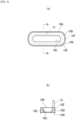
FIG. 4 depicts a nozzle scraper in the aforementioned detoxifying device, wherein (a) is a bottom view of the scraper, viewed from the combustion chamber side, and (b) is a cross-sectional view, in the direction of the arrow, of the section A-A in (a). -
FIG. 5 is an explanatory diagram depicting schematically the operation of a nozzle scraper provided in the nozzle depicted inFIG. 4 . -
FIG. 6 is an operation explanatory diagram for explaining the effects of the aforementioned detoxifying device according to the present invention. - In order to achieve the object of providing a detoxifying device structured so as to enable deposits to be scraped off cleanly, without leaving a scraping residue, even for a nozzle that is provided with a narrow diameter portion and a wide diameter portion that is further to the downstream side than the narrow diameter portion, the present invention is achieved through a structure that is a detoxifying device for detoxifying, through combustion or thermal decomposition within a combustion chamber, a process gas that includes a toxic component, comprising: a nozzle that comprises a narrow diameter portion and a wide diameter portion that is provided further to the downstream side than the narrow diameter portion, said nozzle connected to the top face of the combustion chamber, for introducing the process gas into the combustion chamber; a nozzle scraper that is able to move upward and downward within a prescribed movement range within the wide diameter portion, to remove deposits adhered within the wide diameter portion; and a head scraper for removing the deposits that are adhered to a lower portion of the nozzle scraper, at the bottommost position of the range of movement thereof, wherein: the nozzle scraper has a scraping portion for removing the deposits that are adhered to the inner wall of the wide diameter portion, and a protruding portion that is provided at the bottom end of the narrow diameter portion at the topmost position of the movement range.
- One embodiment according to the present invention will be explained in detail based on the appended drawings. Note that when, in the embodiment described below, there are references to numbers of structural elements, numeric values, quantities, ranges, or the like, there are no limitations to these specific numbers, and the values may be higher or lower, except if explicitly indicated and there is a clear limitation to the specific value by principle.
- Moreover, when there is a reference to a shape or positional relationship for a structural element, this also includes any shapes, or the like, that substantially approximate or are analogous to that shape, except for when explicitly indicated and, for example, cases where it is clear from the principle that this is not the case.
- Moreover, the drawings may enlarge or otherwise exaggerate the portions that are distinctive features, for ease in understanding the distinctive features, and the dimensional proportions, and the like, of structural elements are not necessarily the same as those in practice. Additionally, in cross-sectional drawings, hatching may be omitted for portions of structural elements for ease in understanding the cross-sectional structures of the structural elements.
- Additionally, in the explanation below, expressions that indicate directions, such as up/down or left/right, are not absolute, and, although appropriate for the case of the orientation with which the various portions of the detoxifying device according to the present invention have been drawn, if there is a change in orientation, the interpretations thereof must change depending on the change in orientation. Throughout the explanations of the embodiments as a whole, identical reference symbols will be applied to identical elements.
-
FIG. 1 is a schematic diagram of adetoxifying device 10 according to an embodiment according to the present invention, wherein (a) is a diagram depicting the structure of the mechanism portion thereof, and (b) is a block diagram depicting the functions of the controlling portion thereof.FIG. 2 is a plan view, viewed from thecombustion chamber 11 side, of theinlet head 23, and the surrounding structure, in thedetoxifying device 10 depicted inFIG. 1 . Thedetoxifying device 10 depicted inFIG. 1 andFIG. 2 is a combustion-type detoxifying device, used as means for detoxifying, through combustion or thermal decomposition, a gas that is to be detoxified, that is, as a process gas PG that is an exhaust gas that includes toxic components exhausted from a processing chamber of a well-known semiconductor manufacture equipment, or used as means to similarly detoxify, with an exhaust gas that includes a toxic component that is exhausted from equipment other than semiconductor manufacturing equipment as the process gas PG. - When the process gas PG that is exhausted from the processing chamber of the semiconductor manufacturing equipment is decomposed through combustion, powder is produced as microparticulate dust. For example, when silane gas (SiH4) or dichlorosilane (SiH2C12) is decomposed through combustion, silicon dioxide; silica (SiO2), is produced, or when tungsten tetraflouride (WF6) is decomposed through combustion, tungsten oxide (W2O3) is produced. Given this, these powders are deposited by adhering on the wall faces of the gas introducing
aperture outlet 16A of theprocess gas nozzle 16, which is the gas passage for the process gas, described below, or on the wall face of thebase portion 23A of theinlet head 23 of the combustion chamber 11 (the top face of the combustion chamber 11), to produce deposits (a product) 17 within the process gas nozzle 16 (referencingFIG. 5 ). - The
detoxifying device 10 comprises: a detoxifying devicemain unit 12 that is provided with acombustion chamber 11 into which the exhaust gas that includes the toxic component, described above, that is, the process gas PG, is introduced; amain burner 13 that forms, within thecombustion chamber 11, the flame that is required for detoxification; apilot burner 14 for forming the pilot light PL that is necessary to ignite themain burner 13; theprocess gas nozzle 16 that is the gas passage for introducing the process gas PG into thecombustion chamber 11; ascraper 18 as deposit removing means for removing thedeposits 17, such as the aforementioned silica (SiO2), or the like, that have been deposited on the inner wall, and the surroundings thereof, in the combustion chamber 11 (depicted inFIG. 5 ); atemperature sensor 19 for detecting the temperature within thecombustion chamber 11; adevice controller 20, as the controlling portion for controlling the overall operation of the device, and the like. Note that thedevice controller 20 is, for example, a computer, and includes a program for running the operations of the device as a whole through a predetermined process. - The detoxifying device
main unit 12 has afirst cylinder wall 21 that is substantially cylindrical, and asecond cylinder wall 22 that, similarly, is substantially cylindrical, located on the outside of thefirst cylinder wall 21. The top face of thefirst cylinder wall 21 and the top face of thesecond cylinder wall 22 are both closed by a sharedinlet head 23, with the bottom face side closed by abottom wall 15, and these are connected, through an exhaust port (not shown) to an exhaust pipe of the factory equipment. Additionally, the interior space of thefirst cylinder wall 21 is configured as acombustion chamber 11, where the space portion between thefirst cylinder wall 21 and thesecond cylinder wall 22 is configured as aburner gas chamber 24 into which aflammable fuel 25 andair 26 are introduced. Note that thefirst cylinder wall 21 and thesecond cylinder wall 22 need not necessarily have round cylindrical shapes. - The
main burner 13 for forming, within thecombustion chamber 11, the flame that is required for detoxification has a firstmain burner 13A that is provided on the inner periphery of theburner gas chamber 24, and a secondmain burner 13B that is provided on theinlet head 23 that structures the top wall of thecombustion chamber 11. - The
base portion 23A of theinlet head 23 that forms the top face of thefirst cylinder wall 21 and thesecond cylinder wall 22 is formed in a disk shape that fits with the cylindrical shapes of thefirst cylinder wall 21 and thesecond cylinder wall 22, as illustrated inFIG. 2 . The secondmain burner 13B,head scraper 18B,temperature sensor 19, andpilot burner 14 are attached to thebase portion 23A of theinlet head 23. - As illustrated in
FIG. 1 , the firstmain burner 13A has a structure wherein a plurality ofjet holes 21A is formed in thefirst cylinder wall 21 that structures theburner gas chamber 24, where amixed gas 27 of aflammable fuel 25 andair 26 is expelled from the jet holes 21A toward thecombustion chamber 11, enabling combustion. Consequently, a first flammablegas supplying nozzle 28 for supplying theflammable fuel 25 into theburner gas chamber 24, and a second flammablegas supplying nozzle 29 for supplying theair 26 into theburner gas chamber 24, are connected to thesecond cylinder wall 22. - Similarly, as illustrated in
FIG. 1 , the secondmain burner 13B has aprocess gas nozzle 16 as the gas passage for the process gas, for introducing the process gas PG into thecombustion chamber 11. Theprocess gas nozzle 16 is open as the gas introducingaperture outlet 16A in thebase portion 23A of theinlet head 23, that is, the top face of thecombustion chamber 11. Note that theprocess gas nozzle 16 inlet side is connected to the outlet side of the processing chamber of the semiconductor manufacturing equipment, not shown, that discharges the process gas PG. Given this, in thedetoxifying device 10, the process gas PG that is sent from the processing chamber is introduced into thecombustion chamber 11 from theprocess gas nozzle 16. Note that there is no particular limitation on the number ofprocess gas nozzle 16, where, in the present embodiment, this number is 4, as depicted inFIG. 2 , disposed with substantially equal spacing around a reference circle C1 that surrounds the fourprocess gas nozzles 16. Additionally, in the secondmain burner 13B, a third flammablegas supplying nozzle 30 is connected within theprocess gas nozzle 16, where theflammable fuel 25 and the oxygen (or air) 26 is supplied from the connected third flammablegas supplying nozzle 30 into theprocess gas nozzle 16. In addition, the structure is such thatmixed gas 27 of theflammable fuel 25 and the oxygen (or air 26) is expelled from theprocess gas nozzle 16 gas introducingaperture outlet 16A toward thecombustion chamber 11, enabling combustion. - The
process gas nozzle 16 is depicted also inFIG. 3 as a partial enlarged cross-sectional drawing ofFIG. 1 .FIG. 3 is an enlarged diagram depicting theprocess gas nozzle 16, indicated by reference symbol (N) inFIG. 1 , and the surrounding structure, where (a) is a cross-sectional drawing, and (b) is a cross-sectional view, in the direction of the arrow, for the section B-B in (a). AddingFIG. 3 toFIG. 1 andFIG. 2 to explain the structure of theprocess gas nozzle 16 further, theprocess gas nozzle 16 comprises afirst nozzle part 16G, having anarrow diameter portion 16B, and asecond nozzle part 16H, having awide diameter portion 16C, provided on the downstream side of thenarrow diameter portion 16B of thefirst nozzle part 16G. - The
narrow diameter portion 16B, as thefirst nozzle part 16G, is formed so that the opening diameter gradually becomes narrower toward thesecond nozzle part 16H side from the process chamber side, formed, for example, as an orifice tube, a Venturi tube, or the like. When thenarrow diameter portion 16B is formed as an orifice tube, a Venturi tube, or the like, the detoxification efficiency is improved through mixing well the fuel and the oxygen for combustion through the sudden expansion at the discontinuity in the flow at the orifice part or the Venturi part. The gas introducingaperture outlet 16D of thenarrow diameter portion 16B is connected securely to thewide diameter portion 16C through aflange 16F and aflange 16E on thenarrow diameter portion 16B side, as depicted inFIG. 3 (a) . Note that the gas introducingaperture outlet 16D of thenarrow diameter portion 16B passes vertically through theflange 16E to protrude a prescribed amount into thewide diameter portion 16C. The shape of the gas introducingaperture outlet 16D is formed elliptically, as depicted inFIG. 3 (b) . - On the other hand, in the
wide diameter portion 16C, as thesecond nozzle part 16H, theflange 16F, on one end side (the top end side) is connected securely through theflange 16E to the gas introducingaperture outlet 16D of thenarrow diameter portion 16B. As depicted inFIG. 3 (a) , thewide diameter portion 16C has an inner diameter that is larger than the outer diameter of thenarrow diameter portion 16B so that a gap S from the gas introducingaperture outlet 16D of thenarrow diameter portion 16B is formed around the entire periphery, and, as depicted inFIG. 3 (b) , thewide diameter portion 16C is formed in the shape of an ellipse, as was thenarrow diameter portion 16B. Note that, as depicted inFIG. 3 (a) , thewide diameter portion 16C is formed in a tube shape that has a constant diameter from the one end side (the top end side) until the bottom end side, where the gas introducingaperture outlet 16A is provided, formed with an elliptical cross-sectional shape. - The
pilot burner 14 has apilot nozzle 14A, provided in the vicinity of theprocess gas nozzle 16. The structure is such that the outlet side of the nozzle 14Ais open to the top face of the combustion chamber 11 (thebase portion 23A), wheremixed gas 27 of theflammable fuel 25 and the air (or oxygen) 26 is expelled from the outlet of thenozzle 14A toward thecombustion chamber 11, enabling combustion. Note that the position of thenozzle 14A that is provided on the top face of thecombustion chamber 11 is provided at a position that is further toward the inside of the reference circle C1 that surrounds the four gas introducingaperture outlets 16A within thecombustion chamber 11, as depicted inFIG. 2 . - The
temperature sensor 19 is for measuring the temperature within thecombustion chamber 11, and is formed in a pin-shape, attached to theinlet head 23 in a state wherein one end side protrudes into thecombustion chamber 11. The position in the top face of thecombustion chamber 11 at which thetemperature sensor 19 is provided is a position that is further to the outside than the reference circle C1 that surrounds the four gas introducingaperture outlets 16A within thecombustion chamber 11, and to the outside of a reference circle C2. - The
scraper 18 has anozzle scraper 18A for removingdeposits 17 that are adhered within the nozzle (the process gas passage) 16 and expelling them from the gas introducingaperture outlets 16A into thecombustion chamber 11, and ahead scraper 18B for removing thedeposits 17 that were adhered to the base portion (top face) 23A of thecombustion chamber 11 and thedeposits 17, and the like, that remain adhered to the bottom end of thenozzle scraper 18A. - The
nozzle scraper 18A is configured so as to undergo horizontal movement in the vertical direction, within a prescribed movement range, within thewide diameter portion 16C of theprocess gas nozzle 16, where, during this movement, thedeposits 17 that are adhered to the inner peripheral wall face of thewide diameter portion 16C are scraped off and expelled into thecombustion chamber 11. As illustrated inFIG. 3 andFIG. 4 , thenozzle scraper 18A is formed so that the outer shape of themain unit portion 18D is substantially equal to the inner diameter of thewide diameter portion 16C, and a throughhole 18C, that passes through in the vertical direction and that is shaped, in the plan view, substantially identically with the gas introducingaperture outlet 16D of thenarrow diameter portion 16B, is formed in the center of themain unit portion 18D, to form a ring shape. That is, aninside protruding part 18E is formed all the way around on the center side of thenozzle scraper 18A up to a position that covers the bottom end face of thenarrow diameter portion 16B in the state wherein thenozzle scraper 18A has been moved to a "standby position" (the topmost position of the movement range), depicted inFIG. 3 (a) . Consequently, themain unit portion 18D of thenozzle scraper 18A functions as a protruding portion for covering the entirety of the top face of thewide diameter portion 16C in the state wherein it has been moved to the "standby position," depicted inFIG. 3 (a) . - Moreover, in the top face of the
main unit portion 18D in thenozzle scraper 18A is provided a protrudingportion 18F that is able to enter into the gap S between the outer periphery of the bottom end portion of thenarrow diameter portion 16B and the inner periphery of thewide diameter portion 16C, in the "standby position," as depicted inFIG. 3 (a) . On the other hand, a scrapingportion 18G is provided, as an edge-shaped blade that faces downward along the inner peripheral surface of thewide diameter portion 16C, in the bottom face side of thenozzle scraper 18A. When thenozzle scraper 18A moves into the "standby position," the protrudingportion 18F in thenozzle scraper 18A enters into the gap S between the outer periphery of the bottom end portion of thenarrow diameter portion 16B and the inner periphery of thewide diameter portion 16C, allowing a portion (theinside protruding part 18E) of the top face of themain unit portion 18D of thenozzle scraper 18A to contact the bottom face of thenarrow diameter portion 16B. - In the
scraping portion 18G of thenozzle scraper 18A, the outer peripheral side tip end part is formed in the shape of a sharp blade, and when thenozzle scraper 18A moves toward the downward direction from the "standby position," thedeposits 17 that are adhered to the inner wall of thewide diameter portion 16C are scraped off toward thecombustion chamber 11. - Additionally, a
rod 31, for moving thenozzle scraper 18A in the vertical direction from the outside of theprocess gas nozzle 16, is provided on the top face of themain unit portion 18D in thenozzle scraper 18A. Note that the structure is such that the movement of therod 31 in the vertical direction is run by operation of a drivingportion 20A that has an electric motor (not shown) as the driving force, controlled by thedevice controller 20 that is depicted inFIG. 1 (b) . Additionally, when thenozzle scraper 18A is moved to the bottommost position by therod 31, the scrapingportion 18G on the bottom face side protrudes slightly, together with thedeposits 17, into thecombustion chamber 11. - The
head scraper 18B is formed by a plate-shaped member, and is attached, so as to be able to rotate together with arotatable shaft 33, to the bottom end side of theshaft 33, which passes through substantially the center of theinlet head 23. Thehead scraper 18B is attached in a state that rotates so as to slide substantially horizontally within thecombustion chamber 11 and on the bottom face of theinlet head 23, that is, the base portion (the top face) 23A of thecombustion chamber 11. The structure is such that the rotation of theshaft 33, that is, the rotation of thehead scraper 18B, happens automatically through operation of the drivingportion 20B that has, as its driving force, an electric motor (not shown) that is controlled by thedevice controller 20. -
FIG. 5 is an operation explanatory diagram for removing thedeposits 17 within theprocess gas nozzle 16 in thedetoxifying device 10. The operation of thedetoxifying device 10, depicted inFIG. 1 through FIG. 4 , will be explained by adding the operation explanatory diagram ofFIG. 5 , in addition toFIG. 1 through FIG. 4 . Note that for simplicity in the explanation, inFIG. 5 theprocess gas nozzle 16, thescraper 18, and the like are further simplified, where only the members requiring explanation are depicted schematically. - In the
detoxifying device 10, when a device start signal is applied by thedevice controller 20, a pilot light PL is formed by thepilot burner 14 in thecombustion chamber 11, as illustrated inFIG. 1 . This pilot light PL is set so as to always be maintained in the lit state. - Moreover, the
flammable fuel 25 is supplied from the first flammablegas supplying nozzle 28, andair 26 is supplied from the second flammablegas supplying nozzle 29 as well, to the firstmain burner 13A. - The
flammable fuel 25 and the flammable gas (the air 26) that are supplied to the firstmain burner 13A becomemixed gas 27, and are expelled from the firstmain burner 13A toward thecombustion chamber 11. Additionally, the igniting effect by the pilot light PL is applied, at thepilot burner 14, to themixed gas 27 that was expelled, to form, within thecombustion chamber 11, the flame that is required to detoxify the process gas PG. - Note that in supplying the process gas PG to the
combustion chamber 11, it is supplied together with the flammable gas (air or oxygen) from the third flammablegas supplying nozzle 30 after the flame is formed. Given this, thisdetoxifying device 10 converts the toxic gas into non-toxic gas through causing an oxidation reaction by combusting the process gas PG and reacting it with air (oxygen) in thecombustion chamber 11. Following this, the process gas PG that has been detoxified by combustion or thermal decomposition by the flame is discharged, as a processed gas, to the outside of the detoxifying devicemain unit 12 from an outlet port, not shown, that is in communication with thecombustion chamber 11. - Moreover, conversely, when a command signal for stopping combustion (thermal decomposition) is applied to the
detoxifying device 10 from thedevice controller 20, the supplies of theflammable fuel 25 and air (or oxygen) 26 and 27, and of the process gas PG, and the like, from the first flammablegas supplying nozzle 28, the second flammablegas supplying nozzle 29, and the third flammablegas supplying nozzle 30 to the main burners 13 (13A and 13B) are all stopped. When this is done, the flame within thecombustion chamber 11 goes out naturally. Given this, the combustion or thermal decomposition of the process gas PG by the flame within thecombustion chamber 11 is stopped as well through the natural extinguishing of the flame. - Additionally, once the combustion or thermal decomposition of the process gas PG by the flame within the
combustion chamber 11 has been ended, thedevice controller 20 drives thescraper 18, either periodically or as needed, to carry out an operation for removing thedeposits 17 that are adhered within the nozzle (the gas passage) 16 and thedeposits 17 that are adhered in the vicinity of theprocess gas nozzle 16 within thecombustion chamber 11. Thenozzle scraper 18A and thehead scraper 18B are actuated in the operation for removing thedeposits 17. - In removing the
deposits 17 that are adhered and deposited within the nozzle (the gas passage) 16, thedevice controller 20 controls the driving of the drivingportion 20A, and the drivingportion 20A causes thenozzle scraper 18A to undergo reciprocating motion, within a prescribed range of movement, in the vertical direction (the direction of the gas passage) within thewide diameter portion 16C. Note that thenozzle scraper 18A, during the driving operation of thedetoxifying device 10, is positioned at the "standby position," as depicted inFIG. 4 (a) andFIG. 5 (A) , through therod 31, under control by thedevice controller 20. Given this, themain unit portion 18D covers the top face of thewide diameter portion 16C and the peripheral edge part of the bottom face of thenarrow diameter portion 16B that is provided with the gas introducingaperture outlet 16D. - When, accompanying driving operations of the
detoxifying device 10,deposits 17 are deposited through adhering to thewide diameter portion 16C of theprocess gas nozzle 16, as depicted inFIG. 5 (b) , thedevice controller 20 moves thenozzle scraper 18A downward, by therod 31, as depicted inFIG. 5 (c) . Through this downward movement of thenozzle scraper 18A, the scrapingportion 18G moves downward while scraping off thedeposits 17 that are deposited adhered to the inner peripheral surface of thewide diameter portion 16C, and thedeposits 17 that have been scraped off are expelled through falling into thecombustion chamber 11. Moreover, simultaneously the main unit portion (protruding portion) 18D moves thedeposits 17, which were adhered and deposited on the top face part of thewide diameter portion 16C, downward, and at the bottommost movement position of thenozzle scraper 18A, thedeposits 17 that have been moved together with themain unit portion 18D downward are, similarly, exposed within thecombustion chamber 11 from the gas introducingaperture outlet 16D, as depicted inFIG. 5 (c) . That is, in the present embodiment, the position depicted inFIG. 5 (c) is the bottommost position. - Additionally, the
device controller 20 causes theshaft 33 to be rotated by the drivingportion 20B, causing thehead scraper 18B to rotate horizontally together with theshaft 33. The horizontal rotation of thehead scraper 18B rotates within thecombustion chamber 11 so as to slide on the base portion (the top face) 23A of theinlet head 23, and thehead scraper 18B scrapes off and removes thedeposits 17 that are deposited adhered to the top face of thecombustion chamber 11, and also scrapes off thedeposits 17 that are adhered to the bottom end part of thenozzle scraper 18A that has been moved to the bottommost position, expelling them by causing them to fall into thecombustion chamber 11. Note that even if thetemperature sensor 19 is protruding, acontact avoiding portion 32 is provided in thehead scraper 18B so that, during the rotation of thehead scraper 18B, thetemperature sensor 19 is avoided by thecontact avoiding portion 32, enabling scraping of thedeposits 17 to continue without interference with thetemperature sensor 19. - Additionally, once removal of the
deposits 17 by thehead scraper 18B has been completed, thedevice controller 20 stops rotation of thehead scraper 18B and also moves thenozzle scraper 18A from the bottommost position, depicted inFIG. 5 (c) , to the "standby position," which is the topmost position, depicted inFIG. 5 (d) . The operations for removing thedeposits 17 by thenozzle scraper 18A and for removing thedeposits 17 by thehead scraper 18B are completed thereby. - Moreover, with the
nozzle scraper 18A in thedetoxifying device 10 according to the present embodiment, a portion (theinside protruding part 18E) of the top face of the main unit portion (the protruding portion) 18D is formed as a protruding portion so as to contact the bottom face of thenarrow diameter portion 16B when thenozzle scraper 18A is in the "standby position," making it possible to expel and remove, all at once, thedeposits 17 that are deposited adhered over the entirety of the inner surface of thewide diameter portion 16C when scraping off through thenozzle scraper 18A. - This will be explained further by comparing to the case of a structure wherein the top face of the main unit portion (protruding portion) 18D does not cover the bottom face of the
narrow diameter portion 16B, as illustrated inFIG. 6 . As illustrated inFIG. 6 , when the top face of the main unit portion (the protruding portion) 18D does not cover the bottom face of thenarrow diameter portion 16B, a portion of the deposits 17 (residual deposits 17A) will remain on the bottom face of thenarrow diameter portion 16B where the gas introducingaperture outlet 16D is provided, as depicted inFIG. 6 (c) , when thenozzle scraper 18A moves to the bottommost position from the "standby position" ofFIG. 6 (a) and (b) . This will remain even after thenozzle scraper 18A has returned from the bottommost position to the "standby position" that is illustrated inFIG. 6 (d) . In contrast, with the structure of the present embodiment, themain unit portion 18D is formed so that a portion (theinside protruding part 18E) of the top face of the main unit portion (protruding portion) 18D of thescraper 18A will contact the bottom face of thenarrow diameter portion 16B with thenozzle scraper 18A at the "standby position," enabling all of thedeposits 17 that are adhered over the entire surface of thewide diameter portion 16C to be expelled and removed, without residual, when scraped off by thenozzle scraper 18A. This makes it possible to shorten the maintenance time, and to anticipate an improvement in productivity. - The
main unit portion 18D is formed so that a portion (theinside protruding part 18E) of the main unit portion (protruding portion) 18D of thenozzle scraper 18A will contact and cover the bottom face of thenarrow diameter portion 16B with thenozzle scraper 18A in the "standby position." Through this, thedeposits 17 that are directed toward the bottom face of thenarrow diameter portion 16B within thewide diameter portion 16C will not adhere to the bottom face of thenarrow diameter portion 16B, but will adhere to the portion (theinside protruding part 18E) of the top face of themain unit portion 18D, enabling prevention of direct adhesion of deposits 17 (residual deposits 17A) on the bottom face of thenarrow diameter portion 16B wherein the gas introducingaperture outlet 16D is provided. - Moreover, because, in the present embodiment, the movement of the
nozzle scraper 18A is up/down movement, this enables processing by expelling thedeposits 17 within thewide diameter portion 16C smoothly into thecombustion chamber 11 even if the cross-sectional shape of thewide diameter portion 16C is rectangular, substantially square, elliptical, or the like, rather than being limited to circular. - Furthermore, the
nozzle scraper 18A moves up and down within thewide diameter portion 16C that is provided further to the downstream side than thenarrow diameter portion 16B, enabling easy application even in cases wherein, for example, an orifice, Venturi tube, or the like, is used wherein anarrow diameter portion 16B, and awide diameter portion 16C that is further to the downstream side than thenarrow diameter portion 16B, are provided. - Note that the present invention may be modified or combined in a variety of ways without deviating from the spirit or intent thereof, and obviously the present invention extends to these modifications and combinations.
- Moreover, the present invention is not limited to a
process gas nozzle 16 of adetoxifying device 10, but rather may be applied also to other exhaust gas pipes whereindetoxifying devices 10 are used in other parts. -
- 10: Detoxifying Device
- 11: Combustion Chamber
- 12: Detoxifying Device Main Unit
- 13: Main Burner
- 13A: First Main Burner
- 13B: Second Main Burner
- 14: Pilot Burner
- 14A: Nozzle
- 15: Bottom Wall
- 16: Process Gas Nozzle
- 16A: Gas Introducing Aperture Outlet
- 16B: Narrow Diameter Portion
- 16C: Wide Diameter Portion
- 16D: Gas Introducing Aperture
- 16E: Flange
- 16F: Flange
- 16G: First Nozzle Part
- 16H: Second Nozzle Part
- 17: Deposits
- 17A: Residual Deposits
- 18: Scraper
- 18A: Nozzle Scraper
- 18B: Head Scraper
- 18C: Through Hole
- 18D: Main Unit Portion (Protruding Portion)
- 18E: Inside Protruding Portion
- 18F: Protruding Portion
- 18G: Scraping Portion
- 19: Temperature Sensor
- 20: Device Controller (Controlling Portion)
- 20A: Driving Portion
- 20B: Driving Portion
- 21: First Cylinder Wall
- 21A: Jet Hole
- 22: Second Cylinder Wall
- 23: Inlet head
- 23A: Base Portion
- 24: Burner Gas Chamber
- 25: Flammable Fuel
- 26: Air
- 27: Mixed Gas
- 28: First Flammable Gas Supplying Nozzle
- 29: Second Flammable Gas Supplying Nozzle
- 30: Third Flammable Gas Supplying Nozzle
- 31: Rod
- 32: Contact Avoiding Portion
- 33: Shaft
- C1: Reference Circle
- C2: Reference Circle
- PG: Process Gas
- PL: Pilot Light
- S: Gap
Claims (6)
- A detoxifying device for detoxifying, through combustion or thermal decomposition within a combustion chamber, a process gas that includes a toxic component, comprising:a nozzle that comprises a narrow diameter portion and a wide diameter portion that is provided further to the downstream side than the narrow diameter portion, said nozzle connected to the top face of the combustion chamber, for introducing the process gas into the combustion chamber;a nozzle scraper that is able to move upward and downward within a prescribed movement range within the wide diameter portion, to remove deposits adhered within the wide diameter portion; anda head scraper for removing the deposits that are adhered to a lower portion of the nozzle scraper, at the bottommost position of the range of movement thereof, wherein:
the nozzle scraper has:a scraping portion for removing the deposits that are adhered to the inner wall of the wide diameter portion; anda protruding portion that is provided at the bottom end of the narrow diameter portion at the topmost position of the movement range. - A detoxifying device as set forth in claim 1, wherein:
a portion of the protruding portion covers the bottom face of the narrow diameter portion in the standby position wherein the nozzle scraper is stopped. - A detoxifying device as set forth in claim 1 or 2, wherein:
the head scraper is structured from a plate-shaped member, and is provided so as to enable horizontal rotation, facing the top face within the combustion chamber. - A detoxifying device as set forth in any one of claims 1 through 3, further comprising:
a controlling portion for controlling driving of the nozzle scraper and the head scraper. - A detoxifying device as set forth in claim 4, wherein:
the controlling portion drives the head scraper to remove the deposits that are adhered to a lower portion of the nozzle scraper when the nozzle scraper is at the bottommost position of the movement range. - A nozzle scraper used in a detoxifying device for detoxifying, through combustion or thermal decomposition of process gas in a combustion chamber, comprising: a nozzle, which comprises a narrow diameter portion and a wide diameter portion that is provided further to the downstream side than the narrow diameter portion, said nozzle connected to the top face of the combustion chamber, for introducing, into the combustion chamber, a gas to be treated that includes a toxic component, wherein
the nozzle scraper has:a scraping portion for removing deposits that are adhered to the inner wall of the wide diameter portion; anda protruding portion that is provided at the bottom end of the narrow diameter portion at a topmost position of the movement range.
Applications Claiming Priority (2)
| Application Number | Priority Date | Filing Date | Title |
|---|---|---|---|
| JP2021158263A JP7253018B1 (en) | 2021-09-28 | 2021-09-28 | Abatement device and nozzle scraper |
| PCT/JP2022/035250 WO2023054132A1 (en) | 2021-09-28 | 2022-09-21 | Detoxification device and nozzle scraper |
Publications (2)
| Publication Number | Publication Date |
|---|---|
| EP4411223A1 true EP4411223A1 (en) | 2024-08-07 |
| EP4411223A4 EP4411223A4 (en) | 2025-12-03 |
Family
ID=85780245
Family Applications (1)
| Application Number | Title | Priority Date | Filing Date |
|---|---|---|---|
| EP22875999.9A Pending EP4411223A4 (en) | 2021-09-28 | 2022-09-21 | DETOXIFICATION DEVICE AND NOZZLE WIPERS |
Country Status (8)
| Country | Link |
|---|---|
| US (1) | US20240375158A1 (en) |
| EP (1) | EP4411223A4 (en) |
| JP (1) | JP7253018B1 (en) |
| KR (1) | KR20240088683A (en) |
| CN (1) | CN117916525A (en) |
| IL (1) | IL311169A (en) |
| TW (1) | TW202323726A (en) |
| WO (1) | WO2023054132A1 (en) |
Family Cites Families (9)
| Publication number | Priority date | Publication date | Assignee | Title |
|---|---|---|---|---|
| KR0172185B1 (en) * | 1996-01-23 | 1999-02-18 | 김경균 | Apparatus and method for treating harmful waste gases |
| JP2001349521A (en) | 2000-06-09 | 2001-12-21 | Nippon Sanso Corp | Combustion type abatement apparatus and operating method thereof |
| JP5352096B2 (en) * | 2008-02-29 | 2013-11-27 | 三菱重工環境・化学エンジニアリング株式会社 | Combustion furnace and deposit removal mechanism |
| JP5437734B2 (en) * | 2009-08-07 | 2014-03-12 | 株式会社荏原製作所 | Combustion exhaust gas treatment equipment |
| GB2504468B (en) * | 2012-07-27 | 2017-03-22 | Edwards Ltd | Burner Nozzle Reciprocating Scraper Arrangement for Reducing Effluent Gas Deposits |
| JP6113029B2 (en) * | 2013-09-05 | 2017-04-12 | エドワーズ株式会社 | Removal device and abatement device |
| GB2540552A (en) * | 2015-07-20 | 2017-01-25 | Edwards Ltd | Radiant burner head assembly |
| GB2550382B (en) * | 2016-05-18 | 2020-04-22 | Edwards Ltd | Burner Inlet Assembly |
| JP6777472B2 (en) * | 2016-09-06 | 2020-10-28 | エドワーズ株式会社 | Abatement equipment and deposit removal means used in abatement equipment |
-
2021
- 2021-09-28 JP JP2021158263A patent/JP7253018B1/en active Active
-
2022
- 2022-09-21 KR KR1020247006432A patent/KR20240088683A/en active Pending
- 2022-09-21 WO PCT/JP2022/035250 patent/WO2023054132A1/en not_active Ceased
- 2022-09-21 US US18/688,723 patent/US20240375158A1/en active Pending
- 2022-09-21 CN CN202280059676.0A patent/CN117916525A/en active Pending
- 2022-09-21 EP EP22875999.9A patent/EP4411223A4/en active Pending
- 2022-09-21 IL IL311169A patent/IL311169A/en unknown
- 2022-09-27 TW TW111136586A patent/TW202323726A/en unknown
Also Published As
| Publication number | Publication date |
|---|---|
| CN117916525A (en) | 2024-04-19 |
| WO2023054132A1 (en) | 2023-04-06 |
| US20240375158A1 (en) | 2024-11-14 |
| TW202323726A (en) | 2023-06-16 |
| JP7253018B1 (en) | 2023-04-05 |
| IL311169A (en) | 2024-04-01 |
| JP2023053422A (en) | 2023-04-13 |
| KR20240088683A (en) | 2024-06-20 |
| EP4411223A4 (en) | 2025-12-03 |
Similar Documents
| Publication | Publication Date | Title |
|---|---|---|
| EP2463579B1 (en) | Combustion exhaust gas treatment device | |
| US5183646A (en) | Incinerator for complete oxidation of impurities in a gas stream | |
| CN101069041B (en) | Reactor Design to Reduce Particle Deposition During Process Contaminant Abatement | |
| WO2018047678A1 (en) | Abatement device and deposit removal means used in abatement device | |
| WO2000032990A1 (en) | Exhaust gas treating device | |
| JPWO2000032990A1 (en) | Exhaust gas treatment equipment | |
| EP3502560B1 (en) | Burner head for exhaust gas treatment device and method for manufacturing same, and combustion chamber for exhaust gas treatment device, and manufacturing method and maintenance method for same | |
| EP0819887A2 (en) | Combusting Exhaust Gas | |
| US20240375158A1 (en) | Detoxification device and nozzle scraper | |
| JP2017211100A (en) | Discharge gas treatment device | |
| CN111306558B (en) | Device and system for controlling decomposition and oxidation of gas pollutants | |
| US20100008838A1 (en) | Methods and apparatus for abating electronic device manufacturing process effluent | |
| WO2014109152A1 (en) | Inlet nozzle and detoxification device | |
| EP0467989B1 (en) | Incinerator for complete oxidation of impurities in a gas stream | |
| JP6113029B2 (en) | Removal device and abatement device | |
| JP4455564B2 (en) | Rotary kiln for uranium dioxide production | |
| JP4987380B2 (en) | Flame retardant decomposition burner | |
| NL2032864B1 (en) | An exhaust abatement apparatus and a method for abating reactive gasses | |
| RU2534712C1 (en) | Afterburner for anode gases of aluminium electrolyser | |
| EP0493376B1 (en) | Combustion apparatus | |
| JP4840986B2 (en) | Combustion abatement equipment | |
| WO2026099569A1 (en) | Inlet head | |
| UA72816C2 (en) | Burner for obtaining a high-disperce metal oxides |
Legal Events
| Date | Code | Title | Description |
|---|---|---|---|
| STAA | Information on the status of an ep patent application or granted ep patent |
Free format text: STATUS: THE INTERNATIONAL PUBLICATION HAS BEEN MADE |
|
| PUAI | Public reference made under article 153(3) epc to a published international application that has entered the european phase |
Free format text: ORIGINAL CODE: 0009012 |
|
| STAA | Information on the status of an ep patent application or granted ep patent |
Free format text: STATUS: REQUEST FOR EXAMINATION WAS MADE |
|
| 17P | Request for examination filed |
Effective date: 20240227 |
|
| AK | Designated contracting states |
Kind code of ref document: A1 Designated state(s): AL AT BE BG CH CY CZ DE DK EE ES FI FR GB GR HR HU IE IS IT LI LT LU LV MC MK MT NL NO PL PT RO RS SE SI SK SM TR |
|
| DAV | Request for validation of the european patent (deleted) | ||
| DAX | Request for extension of the european patent (deleted) | ||
| A4 | Supplementary search report drawn up and despatched |
Effective date: 20251031 |
|
| RIC1 | Information provided on ipc code assigned before grant |
Ipc: F23G 7/06 20060101AFI20251027BHEP Ipc: F23D 14/50 20060101ALI20251027BHEP Ipc: F23J 1/06 20060101ALI20251027BHEP |