EP0819887A2 - Combusting Exhaust Gas - Google Patents
Combusting Exhaust Gas Download PDFInfo
- Publication number
- EP0819887A2 EP0819887A2 EP97304282A EP97304282A EP0819887A2 EP 0819887 A2 EP0819887 A2 EP 0819887A2 EP 97304282 A EP97304282 A EP 97304282A EP 97304282 A EP97304282 A EP 97304282A EP 0819887 A2 EP0819887 A2 EP 0819887A2
- Authority
- EP
- European Patent Office
- Prior art keywords
- combustion
- nozzle
- exhaust gas
- gas
- combustion nozzle
- Prior art date
- Legal status (The legal status is an assumption and is not a legal conclusion. Google has not performed a legal analysis and makes no representation as to the accuracy of the status listed.)
- Granted
Links
Images
Classifications
-
- F—MECHANICAL ENGINEERING; LIGHTING; HEATING; WEAPONS; BLASTING
- F23—COMBUSTION APPARATUS; COMBUSTION PROCESSES
- F23G—CREMATION FURNACES; CONSUMING WASTE PRODUCTS BY COMBUSTION
- F23G7/00—Incinerators or other apparatus for consuming industrial waste, e.g. chemicals
- F23G7/06—Incinerators or other apparatus for consuming industrial waste, e.g. chemicals of waste gases or noxious gases, e.g. exhaust gases
- F23G7/061—Incinerators or other apparatus for consuming industrial waste, e.g. chemicals of waste gases or noxious gases, e.g. exhaust gases with supplementary heating
- F23G7/065—Incinerators or other apparatus for consuming industrial waste, e.g. chemicals of waste gases or noxious gases, e.g. exhaust gases with supplementary heating using gaseous or liquid fuel
-
- H—ELECTRICITY
- H01—ELECTRIC ELEMENTS
- H01L—SEMICONDUCTOR DEVICES NOT COVERED BY CLASS H10
- H01L21/00—Processes or apparatus adapted for the manufacture or treatment of semiconductor or solid state devices or of parts thereof
- H01L21/02—Manufacture or treatment of semiconductor devices or of parts thereof
-
- F—MECHANICAL ENGINEERING; LIGHTING; HEATING; WEAPONS; BLASTING
- F23—COMBUSTION APPARATUS; COMBUSTION PROCESSES
- F23G—CREMATION FURNACES; CONSUMING WASTE PRODUCTS BY COMBUSTION
- F23G2209/00—Specific waste
- F23G2209/14—Gaseous waste or fumes
- F23G2209/142—Halogen gases, e.g. silane
Landscapes
- Engineering & Computer Science (AREA)
- Environmental & Geological Engineering (AREA)
- Mechanical Engineering (AREA)
- General Engineering & Computer Science (AREA)
- Physics & Mathematics (AREA)
- Condensed Matter Physics & Semiconductors (AREA)
- General Physics & Mathematics (AREA)
- Manufacturing & Machinery (AREA)
- Computer Hardware Design (AREA)
- Microelectronics & Electronic Packaging (AREA)
- Power Engineering (AREA)
- Incineration Of Waste (AREA)
- Pre-Mixing And Non-Premixing Gas Burner (AREA)
- Combustion Of Fluid Fuel (AREA)
- Gasification And Melting Of Waste (AREA)
Abstract
Description
- The present invention relates to a method for combusting an exhaust gas such as silane gas (which is discharged from a reaction furnace of a semi-conductor plant and the like) to form a harmless gas by oxidation, and to an apparatus for carrying out the method.
- Exhaust gas such as silane gas which is discharged from a reaction furnace of semiconductor plants and the like is highly hazardous. Specifically, silane gas is inflammable when brought into contact with air. In order to prevent this silane, or other exhaust gas,is conventionally discharged as harmless gas from the combustion chamber by supplying air to the combustion chamber to combust the exhaust gas as the exhaust gas is discharged from the tip of a burner nozzle provided in the combustion chamber.
- However, when silane gas is combusted, a great amount of silica (SiO2) is produced. Silica exists as microscopic powder, which clogs the narrow bore of the nozzle thereby causing defective combustion in the case where a conventional burner nozzle is used.
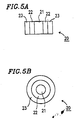
- Conventionally, various technologies for preventing the clogging of the tip of the nozzle have been proposed, such as that illustrated in figures 5A and 5B, which show a
nozzle 20 comprising three concentric tubes. Thenozzle 20 includes a central silanegas introduction tube 21, a combustiongas ejection tube 22 surrounding the silanegas introduction tube 21, and an outermost mixturegas ejection tube 23 for ejecting a mixture gas including the combustion gas and air. Silane gas ejected from the silanegas introduction tube 21 is combusted by bringing the silane gas into contact with a flame which is generated by the mixture gas ejected from the mixturegas ejection tube 23. A combustion "curtain" of combustion gas ejected from the combustiongas ejection tube 22 is generated between the silane gas and the mixture gas. This combustion curtain prevents combustion of the silane gas in the vicinity of the tip of the silanegas introduction tube 21, and thus adhesion of silica to the tip of the nozzle is prevented. However, when a nozzle having such a structure is used, incomplete combustion may occur due to the small amount of air which is available for combustion; also, silane gas having a low concentration may not be removed. - It is an object of the invention to address, and possibly eliminate, the above problems.
- The invention therefore provides a method for combusting an exhaust gas using an exhaust gas combustion nozzle connected to a combustion chamber, the exhaust gas combustion nozzle including an exhaust gas nozzle; a first combustion nozzle being provided so as to surround the exhaust gas nozzle; a second combustion nozzle being provided so as to surround the first combustion nozzle; and an air supply nozzle being provided so as to surround the second combustion nozzle, wherein a first combustion flame ejected from the first combustion nozzle is a reducing flame, and a second combustion flame ejected from the second combustion nozzle is a subsequentially complete combustion flame.
- The method may include the steps of introducing an exhaust gas through the exhaust gas nozzle at a flow velocity of 1 to 8 metres/second; forming a reducing flame by ejecting a first mixture gas obtained by mixing a fuel gas with air at a mixing ratio (by weight) of fuel gas:air of 1:3 to 1:10 through the first combustion nozzle at a flow velocity of 3 to 5 metres/second; and forming a substantially complete combustion flame by ejecting a second mixture gas obtained by mixing a fuel gas with air at a mixing ratio by weight of fuel:air of 1:14 to 1:16 through the second combustion nozzle at a flow velocity of 5 to 7 metres/second.
- An oxygen deficient, or substoichiometric, combustion ratio may be formed by the first combustion flame from the first combustion nozzle so as to surround the exhaust gas introduced into the combustion chamber through the exhaust gas nozzle.
- In another aspect of the invention, in an apparatus for combusting an exhaust gas including an exhaust gas combustion nozzle connected to a combustion chamber, the exhaust gas combustion nozzle includes an exhaust gas nozzle provided at the centre of the exhaust gas combustion nozzle; an annular first combustion nozzle provided so as to surround the exhaust gas nozzle, the first combustion nozzle being capable of forming an oxygen deficient combustion region around the exhaust gas nozzle; a second combustion nozzle including a plurality of nozzles each having a small diameter arranged so as to surround the first combustion nozzle; and an air supply nozzle provided so as to surround the second combustion nozzle.
- According to the present invention, an exhaust gas combustion nozzle has a four-layer structure. Due to a reducing flame curtain formed around an exhaust gas nozzle, combustion of a silane gas is suppressed in the vicinity if the exhaust gas nozzle. The silane gas is completely combusted at a location distant from the exhaust gas nozzle utilising the high temperature obtained from the reducing flame and combustion air supplied thereto. Thus, the silane gas can be completely combusted and removed regardless of the concentration of the silane gas. Since the silane gas is not combusted in the reducing combustion region, there occurs no adhesion of silica, which is a combustion product if a silane gas, onto the tip of the exhaust gas nozzle, the tip of a second combustion nozzle (which is the nozzle for pilot gas) or the tip of a first combustion nozzle (which is a nozzle for main gas). The pilot gas is obtained by mixing fuel gas with a theoretical amount of air and is combusted to provide a complete combustion flame. Therefore, combustion of a pilot flame serving as an ignition source is stable throughout the operation. Thus, the apparatus can be operated safely.
- Thus, the invention prevents the reduction in combustion efficiency due to the clogging if the tip of the nozzle, and also enables gas having a low concentration to be satisfactorily processed.
- The invention will now be described by way of example and with reference to the accompanying drawings, in which:
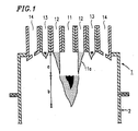
- Figure 1 is a cross-sectional view of an exhaust gas combustion nozzle in accordance with the present invention;
- Figure 2A is a schematic cross sectional view if the exhaust gas combustion nozzle shown in Figure 1;
- Figure 2B is a bottom view of the exhaust gas combustion nozzle shown in Figure 2A;
- Figure 3 is a schematic view of an apparatus for combusting an exhaust gas in accordance with the present invention;
- Figure 4 is a cross sectional view of a second embodiment of an exhaust gas combustion nozzle in accordance with the present invention;
- Figure 5A is a schematic cross sectional view of a conventional exhaust gas combustion nozzle; and
- Figure 5B is a bottom view of the conventional exhaust gas combustion nozzle shown in Figure 5A.
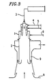
- Figure 3 is a schematic view of an apparatus for combining exhaust gas according to the present invention. The apparatus includes a substantially
cylindrical combustion chamber 2 and an exhaustgas combustion nozzle 1 provided above thecombustion chamber 2. An exhaustgas introduction tube 3, a first mixture gas introduction tube 4, a second mixture gas introduction tube 5, and an air introduction tube 6 are connected to the exhaustgas combustion nozzle 1. The exhaust gas combusted in the exhaustgas combustion nozzle 1 is discharged below thecombustion chamber 2 and is mixed with air 8 drawn in from outside the nozzle. The mixture gas, after being diluted, is sent outside the apparatus through adischarge path 9 by a blower (not shown). Products obtained by combustion, such as silica, are discharged through thedischarge path 9 together with the air drawn in from outside. - As shown in Figures 1, 2A and 2B, the exhaust
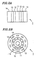
gas combustion nozzle 1 includes anexhaust gas nozzle 11 provided at the centre thereof, an annularfirst combustion nozzle 12 is provided outside theexhaust gas nozzle 11, asecond combustion nozzle 13 is provided outsidefirst combustion nozzle 12, and anair supply nozzle 14 is provided outside thesecond combustion nozzle 13. Theexhaust gas nozzle 11 is cylindrical and is connected to the exhaustgas introduction tube 3. Exhaust gas such as silane gas is introduced into the exhaustgas combustion nozzle 1 downward from theexhaust gas nozzle 11. The flow velocity of the exhaust gas introduced from theexhaust gas nozzle 11 is preferably 1 to 8 metres/second. By setting the flow velocity of the exhaust gas at a relatively high level, adhesion of the products obtained by combusting silane gas (such as silica) to the tip of theexhaust gas nozzle 11 can be effectively prevented. - The
first combustion nozzle 12 is connected to the mixture gas introduction tube 4, and a first mixture gas is ejected from thefirst combination nozzle 12. A first combustion flame is generated by the first mixture gas ejected from thefirst combustion nozzle 12. The first combustion flame is obtained by substoichiometric, oxygen deficient, combustion. The first mixture gas is preferably in the ratio (by weight) of combustion gas and air of 1:5 to 1:10 (1:15 in the case of complete, stoichiometric, combustion). By such oxygen deficient combination, a reduction combustion area is produced. The flow velocity of the first mixture gas is preferably 3 to 5 metres/second. - The
second combustion nozzle 13 is formed of a plurality of small-diameter nozzles arranged in a ring around thefirst combustion nozzle 12 at an appropriate interval. The small-diameter nozzles can be, for example, circular or elliptical. Thesecond combustion nozzle 13 is connected to the second mixture gas introduction tube 5. A second combustion flame ejected from thesecond combustion nozzle 13 is a so-called pilot flame. The second mixture gas is preferably in the ratio (by weight) of combustion gas and air of 1:14 to 1:16, so that complete combustion is realised to maintain safe operation of the apparatus. In order to maintain safe operation of the apparatus, the flow velocity of the second mixture gas is preferably 5 to 7 metre/second. - As shown in Figure 2B, the
air supply nozzle 14 is formed as a plurality of nozzles arranged around thesecond combustion nozzle 13 at an appropriate interval. The nozzles can be, for example, circular, elliptical or rectangular. Theair supply nozzle 14 is connected to the air introduction tube 6. A sufficient amount of air for combustion is supplied from theair supply nozzle 14 to realise complete combustion in the combustion range. In Figure 1, letter a indicates the reduction combustion area, and letter b indicates the complete combustion area. - The method and apparatus according to the present invention functions as follows:
- Exhaust gas, such as silane gas, is introduced from the
exhaust gas nozzle 11 provided in the exhaustgas combustion nozzle 1 and the oxygen deficient first combustion flame is ejected from thefirst combustion nozzle 1. The pilot flame is constantly combusted in thesecond combustion nozzle 13. Even when a sufficient amount of air is supplied from theair supply nozzle 14, the exhaust gas is not substantially combusted at the tip of thefirst combustion nozzle 12 since the combustion flame ejected from thefirst combustion nozzle 12 is a reducing flame as shown in Figure 1. Silica, which is obtained by combusting silane gas, does not clog the tip of the first and second combination nozzles 12 and 13. In thesecond combustion nozzle 13, a stable flame is maintained for safe operation by mixing the combustion gas with a theoretical amount of air. In other words, an accidental fire does not occur. A sufficient amount of air supplied from theair supply nozzle 14 allows the mixture gas and uncombusted gas from thefirst combustion nozzle 12 and the exhaust gas such as silane gas from theexhaust gas nozzle 11 to be completely combusted. - As shown in Figure 4, an exhaust
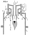
gas combustion nozzle 1 includes anexhaust gas nozzle 11, an annularfirst combustion nozzle 12, asecond combustion nozzle 13, and anair supply nozzle 14. The tip of theexhaust gas nozzle 11 projects downward from the tip of the first andsecond combustion nozzles second combustion nozzle 13 is formed by an opening in a slantedsurface 16. Theair supply nozzle 14 is formed by an opening in a slantedsurface 17. Theair supply nozzle 14 is substantially level with or positioned slightly below a tip area 11a of theexhaust gas nozzle 11. - Using the nozzle shown in Figure 4, silane gas having a concentration of about 0.5 to 100% was introduced into the exhaust
gas combustion nozzle 1 from theexhaust gas nozzle 11 at a flow velocity of 1 to 8 metres/second. A first mixture gas (the mixture ratio by weight of the combination gas and air being about 1:10) was ejected from thefirst combustion nozzle 12 at a flow velocity of 3 metres/second, a second mixture gas (the mixture ratio by weight of the combustion gas and air being about 1:15) was ejected from thesecond combustion nozzle 13 at a flow velocity of 7 metres/second, and a sufficient amount of air was ejected from theair supply nozzle 14. Thus, silane gas was combusted. After combusting the silane gas for 15 days, no adhesion of silica to any of the nozzles was observed. The temperature of the combustion chamber was 250 to 400°C.
Claims (5)
- A method for combusting an exhaust gas using an exhaust gas combustion nozzle connected to a combustion chamber, wherein the exhaust gas combustion nozzle comprises; an exhaust gas nozzle; a first combustion nozzle provided so as to surround the exhaust gas nozzle; a second combustion nozzle provided so as to surround the first combustion nozzle; and an air supply nozzle provided so as to surround the second combustion nozzle, and wherein a first combustion flame ejected from the first combustion nozzle is a reducing flame, and a second combustion flame ejected from the second combustion nozzle is a subsequently complete combustion flame.
- A method for combusting an exhaust gas according to claim 1, comprising the steps of introducing an exhaust gas through the exhaust gas nozzle at a flow velocity of 1 to 8 metres/second; forming a reducing flame by ejecting a first mixture gas obtained by mixing a fuel gas with air at a mixing ratio by weight of fuel gas:air of 1:3 to 1:10 through the first combustion nozzle at a flow velocity of 3 to 5 metres/second; and forming a substantially complete combustion flame by ejecting a second mixture gas obtained by mixing a fuel gas with air at a mixing ratio by weight of fuel gas:air of 1:14 to 1:16 through the second combustion nozzle at a flow velocity of 5 to 7 metres/second.
- A method for combusting an exhaust gas according to claim 1 or claim 2; wherein an oxygen deficient combustion region is formed by the first combustion flame from the first combustion nozzle so as to surround the exhaust gas introduced into the combustion chamber through the exhaust gas nozzle.
- An apparatus for combusting an exhaust gas, comprising an exhaust gas combustion nozzle connected to a combustion chamber, wherein the exhaust gas combination nozzle includes an exhaust gas nozzle provided at a centre of the exhaust gas combustion nozzle; an annular first combustion nozzle provided so as to surround the exhaust gas nozzle, the first combustion nozzle being capable of forming an oxygen deficient combustion region around the exhaust gas nozzle; a second combustion nozzle including a plurality of nozzles each having a small diameter arranged so as to surround the first combustion nozzle; and an air supply nozzle provided so as to surround the second combustion nozzle.
- An apparatus as claimed in Claim 4 wherein the second combustion nozzle is formed as a plurality of separate nozzles arranged so as to encircle the first combustion nozzle.
Applications Claiming Priority (3)
| Application Number | Priority Date | Filing Date | Title |
|---|---|---|---|
| JP15859996 | 1996-06-19 | ||
| JP158599/96 | 1996-06-19 | ||
| JP15859996A JP3490843B2 (en) | 1996-06-19 | 1996-06-19 | Exhaust gas combustion method and apparatus |
Publications (3)
| Publication Number | Publication Date |
|---|---|
| EP0819887A2 true EP0819887A2 (en) | 1998-01-21 |
| EP0819887A3 EP0819887A3 (en) | 1998-10-28 |
| EP0819887B1 EP0819887B1 (en) | 2003-08-27 |
Family
ID=15675220
Family Applications (1)
| Application Number | Title | Priority Date | Filing Date |
|---|---|---|---|
| EP97304282A Expired - Lifetime EP0819887B1 (en) | 1996-06-19 | 1997-06-18 | Combusting Exhaust Gas |
Country Status (5)
| Country | Link |
|---|---|
| EP (1) | EP0819887B1 (en) |
| JP (1) | JP3490843B2 (en) |
| KR (1) | KR100268815B1 (en) |
| DE (1) | DE69724358T2 (en) |
| TW (1) | TW335437B (en) |
Cited By (11)
| Publication number | Priority date | Publication date | Assignee | Title |
|---|---|---|---|---|
| WO2001033141A1 (en) * | 1999-11-02 | 2001-05-10 | Ebara Corporation | Combustor for exhaust gas treatment |
| EP1291069A1 (en) * | 2001-08-30 | 2003-03-12 | DAS-DÜNNSCHICHT ANLAGEN SYSTEME GmbH DRESDEN | Process and apparatus for purifying waste gases, particularly fluor-containing, by means of a burner with separated introduction of feed gases |
| EP1312860A1 (en) * | 2000-08-22 | 2003-05-21 | Ebara Corporation | Method and device for combustion type exhaust gas treatment |
| WO2003085321A1 (en) * | 2002-04-11 | 2003-10-16 | DAS-Dünnschicht Anlagen Systeme GmbH Dresden | Device for the purification of exhaust gases consisting of fluorine-containing compounds in a combustion reactor |
| WO2005026616A1 (en) * | 2003-09-12 | 2005-03-24 | Centrotherm Elektrische Anlagen Gmbh + Co. Kg | Method and device for thermal exhaust gas purification |
| EP1605203A2 (en) * | 2004-06-07 | 2005-12-14 | Air Products And Chemicals, Inc. | Burner and process for combustion of a gas capable of reacting to form solid products |
| WO2006117531A1 (en) * | 2005-05-05 | 2006-11-09 | Edwards Limited | Gas combustion apparatus |
| WO2006123092A1 (en) * | 2005-05-16 | 2006-11-23 | Edwards Limited | Gas combustion apparatus |
| WO2008001095A1 (en) * | 2006-06-30 | 2008-01-03 | Edwards Limited | Gas combustion apparatus |
| US7462333B2 (en) | 2002-04-11 | 2008-12-09 | Das-Dunnschicht Anlagen Systeme Gmbh Dresden | Device for the purification of exhaust gases consisting of fluorine-containing compounds in a combustion reactor |
| CN102230631A (en) * | 2011-06-03 | 2011-11-02 | 王兴文 | Burner block of burner part of waste gas burning hot air furnace |
Families Citing this family (8)
| Publication number | Priority date | Publication date | Assignee | Title |
|---|---|---|---|---|
| DE102005040576B4 (en) * | 2005-08-26 | 2007-08-16 | Centrotherm Clean Solutions Gmbh & Co. Kg | Air burners for the combustion of exhaust gases from processes for the treatment of semiconductors |
| KR100623369B1 (en) | 2005-09-05 | 2006-09-12 | 크린시스템스코리아(주) | Burner of a scrubber for a semiconductor manufacture equipment |
| DE102006034885A1 (en) | 2006-07-25 | 2008-08-07 | Daimlerchrysler Ag | Hydrogen and energy production by thermal conversion of silanes |
| JP5232407B2 (en) * | 2007-05-25 | 2013-07-10 | 日本パイオニクス株式会社 | Exhaust gas purification equipment |
| JP2013015232A (en) * | 2011-06-30 | 2013-01-24 | Edwards Kk | Combustion-type exhaust gas treatment apparatus |
| WO2013018576A1 (en) * | 2011-07-29 | 2013-02-07 | エドワーズ株式会社 | Exhaust gas combustion apparatus |
| KR102508353B1 (en) * | 2022-08-29 | 2023-03-13 | 주식회사 원익홀딩스 | Gas processing device |
| KR102508351B1 (en) * | 2022-08-29 | 2023-03-13 | 주식회사 원익홀딩스 | Gas processing device |
Family Cites Families (3)
| Publication number | Priority date | Publication date | Assignee | Title |
|---|---|---|---|---|
| JPS6387519A (en) * | 1986-09-29 | 1988-04-18 | Mitsubishi Jushi Eng Kk | Method of burning waste gas of semiconductor manufacturing apparatus |
| FR2612606B1 (en) * | 1987-03-18 | 1990-09-14 | Air Liquide | METHOD AND DEVICE FOR DESTRUCTION OF TOXIC GASEOUS EFFLUENTS |
| DE19511644A1 (en) * | 1995-03-30 | 1996-10-02 | Das Duennschicht Anlagen Sys | Process and device for cleaning pollutant-containing exhaust gases by chemical conversion |
-
1996
- 1996-06-19 JP JP15859996A patent/JP3490843B2/en not_active Expired - Lifetime
-
1997
- 1997-06-16 TW TW086108311A patent/TW335437B/en not_active IP Right Cessation
- 1997-06-17 KR KR1019970025080A patent/KR100268815B1/en not_active IP Right Cessation
- 1997-06-18 EP EP97304282A patent/EP0819887B1/en not_active Expired - Lifetime
- 1997-06-18 DE DE69724358T patent/DE69724358T2/en not_active Expired - Lifetime
Non-Patent Citations (1)
| Title |
|---|
| None |
Cited By (21)
| Publication number | Priority date | Publication date | Assignee | Title |
|---|---|---|---|---|
| US6736635B1 (en) | 1999-11-02 | 2004-05-18 | Ebara Corporation | Combustor for exhaust gas treatment |
| WO2001033141A1 (en) * | 1999-11-02 | 2001-05-10 | Ebara Corporation | Combustor for exhaust gas treatment |
| US7112060B2 (en) | 1999-11-02 | 2006-09-26 | Ebara Corporation | Burner for treating waste gas |
| EP1312860A4 (en) * | 2000-08-22 | 2007-02-28 | Ebara Corp | Method and device for combustion type exhaust gas treatment |
| EP1312860A1 (en) * | 2000-08-22 | 2003-05-21 | Ebara Corporation | Method and device for combustion type exhaust gas treatment |
| EP1291069A1 (en) * | 2001-08-30 | 2003-03-12 | DAS-DÜNNSCHICHT ANLAGEN SYSTEME GmbH DRESDEN | Process and apparatus for purifying waste gases, particularly fluor-containing, by means of a burner with separated introduction of feed gases |
| WO2003085321A1 (en) * | 2002-04-11 | 2003-10-16 | DAS-Dünnschicht Anlagen Systeme GmbH Dresden | Device for the purification of exhaust gases consisting of fluorine-containing compounds in a combustion reactor |
| US7462333B2 (en) | 2002-04-11 | 2008-12-09 | Das-Dunnschicht Anlagen Systeme Gmbh Dresden | Device for the purification of exhaust gases consisting of fluorine-containing compounds in a combustion reactor |
| WO2005026616A1 (en) * | 2003-09-12 | 2005-03-24 | Centrotherm Elektrische Anlagen Gmbh + Co. Kg | Method and device for thermal exhaust gas purification |
| EP1605203A3 (en) * | 2004-06-07 | 2008-04-16 | Air Products And Chemicals, Inc. | Burner and process for combustion of a gas capable of reacting to form solid products |
| EP1605203A2 (en) * | 2004-06-07 | 2005-12-14 | Air Products And Chemicals, Inc. | Burner and process for combustion of a gas capable of reacting to form solid products |
| WO2006117531A1 (en) * | 2005-05-05 | 2006-11-09 | Edwards Limited | Gas combustion apparatus |
| CN101171455B (en) * | 2005-05-05 | 2012-05-09 | 爱德华兹有限公司 | Gas combustion apparatus |
| TWI391611B (en) * | 2005-05-05 | 2013-04-01 | Edwards Ltd | Gas combustion apparatus |
| US8647111B2 (en) | 2005-05-05 | 2014-02-11 | Edwards Limited | Gas combustion apparatus |
| WO2006123092A1 (en) * | 2005-05-16 | 2006-11-23 | Edwards Limited | Gas combustion apparatus |
| CN101175949B (en) * | 2005-05-16 | 2011-08-31 | 爱德华兹有限公司 | Gas combustion apparatus and method |
| TWI391612B (en) * | 2005-05-16 | 2013-04-01 | Edwards Ltd | Gas combustion apparatus |
| US8662883B2 (en) | 2005-05-16 | 2014-03-04 | Edwards Limited | Gas combustion apparatus |
| WO2008001095A1 (en) * | 2006-06-30 | 2008-01-03 | Edwards Limited | Gas combustion apparatus |
| CN102230631A (en) * | 2011-06-03 | 2011-11-02 | 王兴文 | Burner block of burner part of waste gas burning hot air furnace |
Also Published As
| Publication number | Publication date |
|---|---|
| JPH109551A (en) | 1998-01-16 |
| DE69724358T2 (en) | 2004-07-01 |
| TW335437B (en) | 1998-07-01 |
| EP0819887B1 (en) | 2003-08-27 |
| JP3490843B2 (en) | 2004-01-26 |
| EP0819887A3 (en) | 1998-10-28 |
| KR100268815B1 (en) | 2000-11-01 |
| DE69724358D1 (en) | 2003-10-02 |
| KR980005290A (en) | 1998-03-30 |
Similar Documents
| Publication | Publication Date | Title |
|---|---|---|
| EP0819887B1 (en) | Combusting Exhaust Gas | |
| KR101417181B1 (en) | Combustive destruction of noxious substances | |
| US6736635B1 (en) | Combustor for exhaust gas treatment | |
| JP2939155B2 (en) | Liquid fuel atomizer with small spray angle for combustion | |
| US6565361B2 (en) | Methods and apparatus for burning fuel with low NOx formation | |
| EP0007697B1 (en) | Burner system for gaseous and/or liquid fuels with a minimum production of nox | |
| US5195884A (en) | Low NOx formation burner apparatus and methods | |
| JPH0611120A (en) | Low nox forming gas burner device and method thereof | |
| JPH0765731B2 (en) | Method for burning a fuel containing bound nitrogen | |
| WO1998006978A1 (en) | Combustion type harmful substance removing apparatus | |
| JPS6325242B2 (en) | ||
| JPH074619A (en) | Oxygen - fuel burner mechanism and its operation | |
| US5061463A (en) | Coincinerator apparatus and method for processing waste gases | |
| EP0210314B1 (en) | Method and apparatus for burning fuel | |
| EP0076036B1 (en) | Method and apparatus for burning fuel in stages | |
| US7521035B1 (en) | Method for regenerating a residual substance that contains sulfur and an atomizing burner suited for carrying out said method | |
| JPH0545845B2 (en) | ||
| US3898317A (en) | Method for incinerating flue gases | |
| US5433600A (en) | Burner for the combustion of coke oven gas | |
| EP0224984B1 (en) | Method and burner apparatus for flaring waste gases | |
| KR102564755B1 (en) | The inlet assembly and how it works | |
| EP0152389A2 (en) | Burner for burning pulverulent fuel | |
| EP0657695A2 (en) | Apparatus and process for combusting fluid fuel containing solid particles | |
| JPH06129627A (en) | Method and apparatus for igniting discharged gas | |
| EP0210313A1 (en) | Method and apparatus for burning fuel |
Legal Events
| Date | Code | Title | Description |
|---|---|---|---|
| PUAI | Public reference made under article 153(3) epc to a published international application that has entered the european phase |
Free format text: ORIGINAL CODE: 0009012 |
|
| AK | Designated contracting states |
Kind code of ref document: A2 Designated state(s): BE DE FR GB IT NL SE |
|
| AX | Request for extension of the european patent |
Free format text: AL;LT;LV;RO;SI |
|
| RIN1 | Information on inventor provided before grant (corrected) |
Inventor name: NINO, SAKAE Inventor name: TAKEUCHI, OSAMU |
|
| PUAL | Search report despatched |
Free format text: ORIGINAL CODE: 0009013 |
|
| AK | Designated contracting states |
Kind code of ref document: A3 Designated state(s): AT BE CH DE DK ES FI FR GB GR IE IT LI LU MC NL PT SE |
|
| AX | Request for extension of the european patent |
Free format text: AL;LT;LV;RO;SI |
|
| 17P | Request for examination filed |
Effective date: 19990322 |
|
| AKX | Designation fees paid |
Free format text: BE DE FR GB IT NL SE |
|
| 17Q | First examination report despatched |
Effective date: 20011025 |
|
| GRAH | Despatch of communication of intention to grant a patent |
Free format text: ORIGINAL CODE: EPIDOS IGRA |
|
| RAP1 | Party data changed (applicant data changed or rights of an application transferred) |
Owner name: THE BOC GROUP PLC |
|
| GRAH | Despatch of communication of intention to grant a patent |
Free format text: ORIGINAL CODE: EPIDOS IGRA |
|
| GRAA | (expected) grant |
Free format text: ORIGINAL CODE: 0009210 |
|
| AK | Designated contracting states |
Designated state(s): BE DE FR GB IT NL SE |
|
| REG | Reference to a national code |
Ref country code: GB Ref legal event code: FG4D |
|
| REF | Corresponds to: |
Ref document number: 69724358 Country of ref document: DE Date of ref document: 20031002 Kind code of ref document: P |
|
| REG | Reference to a national code |
Ref country code: SE Ref legal event code: TRGR |
|
| ET | Fr: translation filed | ||
| PLBE | No opposition filed within time limit |
Free format text: ORIGINAL CODE: 0009261 |
|
| STAA | Information on the status of an ep patent application or granted ep patent |
Free format text: STATUS: NO OPPOSITION FILED WITHIN TIME LIMIT |
|
| 26N | No opposition filed |
Effective date: 20040528 |
|
| REG | Reference to a national code |
Ref country code: GB Ref legal event code: 732E |
|
| NLS | Nl: assignments of ep-patents |
Owner name: EDWARDS LIMITED Effective date: 20071113 |
|
| REG | Reference to a national code |
Ref country code: FR Ref legal event code: TP |
|
| REG | Reference to a national code |
Ref country code: FR Ref legal event code: PLFP Year of fee payment: 20 |
|
| PGFP | Annual fee paid to national office [announced via postgrant information from national office to epo] |
Ref country code: GB Payment date: 20160627 Year of fee payment: 20 |
|
| PGFP | Annual fee paid to national office [announced via postgrant information from national office to epo] |
Ref country code: SE Payment date: 20160629 Year of fee payment: 20 Ref country code: BE Payment date: 20160627 Year of fee payment: 20 Ref country code: NL Payment date: 20160626 Year of fee payment: 20 Ref country code: FR Payment date: 20160628 Year of fee payment: 20 |
|
| PGFP | Annual fee paid to national office [announced via postgrant information from national office to epo] |
Ref country code: DE Payment date: 20160628 Year of fee payment: 20 Ref country code: IT Payment date: 20160627 Year of fee payment: 20 |
|
| REG | Reference to a national code |
Ref country code: DE Ref legal event code: R071 Ref document number: 69724358 Country of ref document: DE |
|
| REG | Reference to a national code |
Ref country code: NL Ref legal event code: MK Effective date: 20170617 |
|
| REG | Reference to a national code |
Ref country code: GB Ref legal event code: PE20 Expiry date: 20170617 |
|
| PG25 | Lapsed in a contracting state [announced via postgrant information from national office to epo] |
Ref country code: GB Free format text: LAPSE BECAUSE OF EXPIRATION OF PROTECTION Effective date: 20170617 |
|
| REG | Reference to a national code |
Ref country code: SE Ref legal event code: EUG |