EP4411166A1 - Halter - Google Patents
Halter Download PDFInfo
- Publication number
- EP4411166A1 EP4411166A1 EP23154778.7A EP23154778A EP4411166A1 EP 4411166 A1 EP4411166 A1 EP 4411166A1 EP 23154778 A EP23154778 A EP 23154778A EP 4411166 A1 EP4411166 A1 EP 4411166A1
- Authority
- EP
- European Patent Office
- Prior art keywords
- holder
- spring member
- hook
- elongated flexible
- hook member
- Prior art date
- Legal status (The legal status is an assumption and is not a legal conclusion. Google has not performed a legal analysis and makes no representation as to the accuracy of the status listed.)
- Granted
Links
Images


Classifications
-
- F—MECHANICAL ENGINEERING; LIGHTING; HEATING; WEAPONS; BLASTING
- F16—ENGINEERING ELEMENTS AND UNITS; GENERAL MEASURES FOR PRODUCING AND MAINTAINING EFFECTIVE FUNCTIONING OF MACHINES OR INSTALLATIONS; THERMAL INSULATION IN GENERAL
- F16G—BELTS, CABLES, OR ROPES, PREDOMINANTLY USED FOR DRIVING PURPOSES; CHAINS; FITTINGS PREDOMINANTLY USED THEREFOR
- F16G11/00—Means for fastening cables or ropes to one another or to other objects; Caps or sleeves for fixing on cables or ropes
- F16G11/14—Devices or coupling-pieces designed for easy formation of adjustable loops, e.g. choker hooks; Hooks or eyes with integral parts designed to facilitate quick attachment to cables or ropes at any point, e.g. by forming loops
- F16G11/143—Hooks
-
- F—MECHANICAL ENGINEERING; LIGHTING; HEATING; WEAPONS; BLASTING
- F16—ENGINEERING ELEMENTS AND UNITS; GENERAL MEASURES FOR PRODUCING AND MAINTAINING EFFECTIVE FUNCTIONING OF MACHINES OR INSTALLATIONS; THERMAL INSULATION IN GENERAL
- F16G—BELTS, CABLES, OR ROPES, PREDOMINANTLY USED FOR DRIVING PURPOSES; CHAINS; FITTINGS PREDOMINANTLY USED THEREFOR
- F16G11/00—Means for fastening cables or ropes to one another or to other objects; Caps or sleeves for fixing on cables or ropes
- F16G11/10—Quick-acting fastenings; Clamps holding in one direction only
Definitions
- the present disclosure relates to the field of holders for releasably attaching and holding elongated flexible items such as cables, cords, wires, tubes, hoses or the like to an object.
- the disclosure relates to holders for releasably attaching and holding elongated flexible items from medical equipment to an object in a hospital environment.
- Cables, wires, tubes and the like risk being entangled in other items when hanging freely, consequently risk being damaged or causing damage to- or disconnecting the connected equipment, preventing it from providing its intended function.
- An example of one such environment may be hospitals where different equipment is used at different times, or different procedures may need the wires, cables and tubes arranged differently. Some non-limiting examples of such procedures may be while the equipment is in operation and the patient is receiving treatment, compared to when the patient is walking around, or when the bed in which the patient is laying is transported to another department of the hospital.
- An object of the present disclosure is therefore to provide a solution to the above defined problem, to alleviate at least one drawback of the prior art, and/or to at least provide a suitable alternative.
- the present disclosure relates to a holder for releasably attaching at least one elongated flexible item, such as a cord or a tube, to an object by wrapping the holder at least partly around said object.
- the holder comprises a spring member having a flat body shape with two opposing ends.
- the spring member is bi-stable and movable between a flat state in which the spring member extends in a first direction between the opposing ends, and a curled state. In the curled state the spring member strives to assume a cylindrical shape, and in which curled state the spring member may be wrapped at least partly around the object.
- the holder further comprises a hook member arranged to receive and hold the at least one elongated flexible item.
- a benefit provided by the holder as described above is that elongated flexible items can be fitted into the hook member to receive and hold the elongated flexible item, after which the holder can be snapped around an object by use of the bi-stable spring member to fixate and position the elongated flexible item to a suitable placement, or vice versa.
- This by causing the bi-polar spring to change from a flat state to a curled state.
- the object may be any suitable object, such as a hospital bed, a machine, or a body part, such as a wrist or ankle.
- the fixation and removal of the elongated flexible item is fast, reproducible, and can be done without using tools or leaving any marks to the structure or object to which it is applied.
- It is also a very dynamic holder that can be applied suitably based on the situation at hand, and independently of any specific brand of equipment. This make it suitable to use even if some equipment is exchanged.
- the holder when the holder is in its flat state it is substantially flat, making it easy to store and bring several holders with ease.
- a patient's bed can be equipped with an open container in which the holders may be placed to be easily accessible for the care giver to apply when needed. When the holder is subsequently removed, it can easily be placed back in the open container. Alternatively, the holder can be snapped around the care giver's wrist to be easily accessible to the care giver at all times.
- Another benefit with the holder is that it is easy to remove and clean. Also, equipment that may often need to have elongated flexible items attached to it does not need fixed installations for this purpose, making also the equipment itself easy to clean. This may be particularly important in a hospital environment due to its hygienic requirements.
- the at least one hook member is attached to at least one of the opposing ends of the spring member.
- the holders can also be stored and shipped in a more compact way and shipped in a more economical manner, as every second holder can be placed in the opposite position compared to ones next to them, thereby minimizing the volume when a plurality of holders are handled. Further, when handling a plurality of holders placed in an open container as explained above, the holders are also less prune to entanglement, compared to if the hook member would be placed in the middle of the spring member.
- the at least one hook member is configured to receive the at least one elongated flexible item extending in a second direction parallel to a central axis of the spring member in its curled state. This makes it easier to snap the holder around an object after the elongated flexible item has been attached to the hook member. This is due to that the elongated flexible item is more likely to be out of the way of the spring member as it snaps around an object, i.e. when it goes from the flat state to the curled state. Still optionally, the at least one hook member may extend in the second direction that corresponds to an extension of the spring member in the second direction. For example, the at least one hook member may extend in the second direction so that an elongated recess is formed for the flexible item.
- the at least one hook member has an extension in the second direction that corresponds to an extension of the spring member in the second direction. This way, the elongated flexible item can be reliably attached to the hook member without making the holder taking up unnecessary space in the second direction.
- the holder further comprises a layer of elastic polymer material, such as rubber or silicone, covering at least a part of the spring member.
- the elastic polymer layer makes the holder less likely to scratch the object to which the holder is snapped on. It is also more comfortable to handle for the user.
- the holder is also easy to keep clean, compared to for instance using textile for this purpose.
- the layer of elastic polymer material covers the spring member completely, making it possible to machine wash the holder without exposing the spring member to water and detergents, thereby protecting the holder from corrosion.
- the hook member comprises a base part and a hook part, wherein the base part is configured to connect the hook member to the spring member.
- the hook part is configured to receive and hold the at least one elongated flexible item, wherein an opening for receiving the at least one elongated flexible item is smaller than an inner diameter of the hook part.
- the hook member further comprises an intermediate part between the base part and the hook part.
- the intermediate part is configured to provide structural elasticity in a transition between the base part and the hook part.
- the hook member may adapts its relative position to the flexible item. This then allow for less need of accuracy when fixing the flexible item in the hook part, making the holder easier to work with.
- the intermediate part and the base part has an equal or substantially equal thickness in their intersection. This allows for a more robust holder.
- Thickness may be defined by a direction perpendicular to a plane as defined by the first direction and the second direction when the holder is in a flat state.
- a thickness of the intermediate part increases in a direction from the hook part towards the base part. This allows for more elasticity of the hook member and making the holder easier to fix elongated items to, thus easier to work with.
- the holder has a layer of elastic polymer material, such as rubber or silicone, covering at least a part of the spring member.
- the intermediate part forms at least one abutment closest to the base part.
- the at least one abutment being configured to abut the layer of elastic polymer material.
- the thickness of the intermediate part at the at least one abutment equals or essentially equals a combined thickness of the spring member and the layer of elastic polymer material.
- the hook member is made of plastic.
- Plastic is light, durable, relatively hard and easy to clean.
- a benefit of using a plastic hook member, compared to for instance a metal hook member, is that it is not as hard as the metal hook member. Thereby, it is safer and more comfortable to work with.
- the use of a plastic hook member reduces wear and tear to the surrounding equipment, compared to metal hook members.
- the base part is fully submerged into the layer of elastic polymer material.
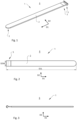
- Fig. 1 depicts a holder 1 according to an example embodiment of the present disclosure.
- the holder 1 may be used for releasably attaching at least one elongated flexible item, such as a cord or a tube (not shown), to an object (not shown) by wrapping the holder 1 at least partly around said object.
- the holder 1 comprises a spring member 2 having a flat body shape with two opposing ends 3.
- the spring member 2 is bi-stable and movable between a flat state 6 in which the spring member 2 extends in a first direction D1 between the opposing ends 3, and a curled state 7 (see Fig. 4 ).
- the holder 1 further comprises a hook member 5 arranged to receive and hold the at least one elongated flexible item (not shown).
- the spring member 2 being bi-stable is meant the spring member 2 has two equilibrium positions. This allows a device with a bi-stable spring to assume two distinct configurations. In this case, for a first equilibrium position the spring member 2 can allow the holder 1 to be flat, or in a flat state 6. For a second equilibrium the spring member 2 can allow the holder 1 to be curled, or in curled state 7.
- the curled state 7 is typically achieved by slapping the holder 1 in a flat state 6 at an object, at which point the holder 1 curls around the object and stays in a roughly circular position.
- the bi-stable spring member 2 may be made by steel.
- the steel may be at least 0, 15mm thick to achieve effective spring effect.
- the flat state 6 may be defined as the state when the spring member 2 is in a first equilibrium position so that opposing ends 3 of the holder 1 are furthest away from each other. At that point the opposing ends 3 extends in a first direction D1.
- the curled state 7 may then be described as when same spring member 2 positioned the same way as in the flat state 6, yet assumes a second equilibrium position and forms an annulus.
- the annulus has a central axis A extending in a second direction D2, where the second direction D2 is transverse to the first direction D1.
- a curled state 7 does not mean the spring member 2 needs to be completely curled. It may also be less curled, such as when attached around blankets, waists etc.
- the curled state 7 may be considered being entered as long as the spring member 2 is not in a flat state 6. In other words, the spring member 2 may be considered in a curled state 7 as soon as it is not in a first equilibrium position.
- releasably attaching a flexible item is meant that it is easy to both attach and detach the flexible item, without the need of any tools or causing any damage to the object to which the flexible item is attached.
- elongated flexible items items such as cables, cords, wires, hoses or tubes, to give a few unlimiting examples.
- Fig. 2 shows a holder 1 according to an example embodiment of the present disclosure from a top view.
- the holder 1 comprising a spring member 2 and a hook member 5 can be seen in a flat state 6.
- the holder 1 extends lengthwise in a first direction D1, and has a first length D1L.
- the holder 1 extends sideways in a second direction D2, which may be referred to as a width direction of the holder 1.
- the holder 1 has a width D2W in the width direction D2.
- the second direction D2 is perpendicular to the first direction D1. It should be understood that the directions are relative in view of the position of the holder 1.
- top view top is meant the perspective when the holder 1 is seen from a point from the center of the holder 1, perpendicular a plane formed by the first direction D1 and the second direction D2 mentioned above.
- the top view may also be called a third direction D3.
- Fig. 3 depicts a holder 1 according to an example embodiment of the present disclosure in a flat state 6 from a side view.
- side view is meant it is seen from the second direction D2.
- Fig. 4 depicts a holder 1 according to an example embodiment of the present disclosure in a curled state 7.
- the bi-stable spring member 2 is in its second equilibrium position, forming an annulus.
- An opening 53 (see Fig. 6 ) of the hook member 5 can be seen facing towards the spring member 2. This may be beneficial in the holder's 1 ability to hold on to an elongated flexible item.
- the opening 53 may also be facing in the opposite direction, making it more accessible to attach and detach elongated flexible items.
- the opening 53 may also be facing any other direction.
- the hook member 5 is here seen placed on one of the opposing ends 3, yet for a holder 1 according to the present disclosure, the hook member 5 may also be placed at other places of the spring member 2.
- the hook member 5 is attached at the middle part of the spring member 2.
- the middle part can be defined as the region of the spring member 2 where the distances to the opposing ends 3 are roughly the same, while the spring member 2 is in a flat state 6.
- Fig. 5 depicts a cross-sectional side view of a holder 1 according to an example embodiment of the present disclosure.
- the holder 1 is seen with a hook member 5 and a spring member 2, where the spring member 2 has a layer of elastic polymer material 4 around it.
- the elastic polymer material 4 may be any of rubber or silicone or similar materials.
- the polymer material 4 provides good friction against a variety of materials, enabling the holder 1 to attach itself firmly and reliable to a variety of objects. Further benefits of a polymer layer are that its ensures easy cleaning, and prevents the spring member 2 from corroding, in case of a steel spring member 2. Further, the polymer layer 4 makes the holder 1 comfortable to handle.
- the polymer layer 4 protects both users, patients, flexible items as well as the various objects the holder 1 is supposed to attach to, from potentially sharp edges of the spring member 2.
- Fig. 5 further shows a cross-section view in the region of the hook member 5.
- the hook member 5 can be seen attached to the flexible spring member 2 by means of the layer of elastic polymer material 4.
- the elastic polymer material 4 and the hook member 5 may have a corresponding shape so that the hook member 5 can be attached by press-fitting the hook member 5 into the elastic polymer material 4.
- the holder 1 and hook member 5 can be made modular so that it is possible to replace the hook member 5 with another one with a more suitable shape or size to receive and hold attach a specific kind of elongated flexible item.
- the hook member 5 may be permanently fixed to the holder 1 during the manufacturing process, where the hook member 5 can be attached in relation the spring member 2 during the process of applying the elastic polymer layer to the spring member 2.
- the layer of elastic polymer material 4 may substantially cover the side of the elastic spring member 2 intended to be wrapped around an object. This way, many of the benefits mentioned above of having a polymer layer is achieved, while using less polymer material 4. Accordingly, a lighter and more cost-effective holder 1 is achieved.
- An intermediate part 55 can be seen having at least one abutment 56 closest to a base part 51.
- the at least one abutment 56 being configured to abut the layer of elastic polymer material 4.
- the thickness (t) of the intermediate part 55 at the at least one abutment 56 equals or essentially equals a combined thickness T of the spring member 2 and the layer of elastic polymer material 4.
- the smooth transition makes the holder 1 easier to both keep clean and clean without any formations prone to collects dirt. As such, the holder 1 is more hygienic to use.
- Fig. 6 depicts a detailed view of a hook member 5 according to an example embodiment of the disclosure.
- the hook member 5 can be seen extending from the spring member 2.
- the hook member 5 has a base part 51 configured for attaching to the spring member 2, and a hook part 52 configured to receive and hold the at least one elongated flexible item.
- An intermediate part 55 is placed between the base part 51 and the hook part 52.
- the intermediate part 55 is configured to provide structural elasticity in a transition between the base part 51 and the hook part 52.
- the hook part 52 may adapts its relative position to the flexible item. This then allows for less need of accuracy when fixing the flexible item in the hook part 52, making the holder 1 easier to use.
- the hook member 5 has an opening 53 for receiving an elongated flexible item.
- the opening 53 extending from a tip of the hook part 52 and the intermediate part 55. Further, an inner diameter 54 of the hook portion is shown.
- the opening 53 for receiving the at least one elongated flexible item is smaller than an inner diameter 54 of the hook part 52.
- the intermediate part 55 and the base part 51 may have an equal or substantially equal thickness. This allows for a more robust holder 1.
- the thickness of the intermediate part 55 increases in a direction from the hook part 52 towards the base part 51. This allows for more elasticity of the hook member 5 and making the hook member 5 better at receiving elongated items, thus easier to work with.
- the thickness increases gradually to correlate to the thickness of the elastic polymer layer covered spring member 2. The thickness may increase gradually such that a smooth transition between the layer of elastic polymer and the hook member 5 may be formed.
- Fig. 7 depicts the magnified view of the hook member 5 from Fig. 5
- the intermediate part 55 forms at least one abutment 56 closest to the base part 51.
- the at least one abutment 56 being configured to abut the layer of elastic polymer material 4.
- the thickness t of the intermediate part 55 at the at least one abutment 56 equals or essentially equals a combined thickness T of the spring member 2 and the layer of elastic polymer material 4. This generates a smooth transition from the spring member 2 and the hook member 5, making the holder 1 less likely to get entangled in other items, thus easier to work with.
- the smooth transition makes the holder 1 easier to both keep clean and to clean without any formations prone to collects dirt. As such, the holder 1 is more hygienic to use.
- the at least one hook member 5 may extend in the second direction D2 so that an elongated recess is formed for the flexible item.
Landscapes
- Engineering & Computer Science (AREA)
- General Engineering & Computer Science (AREA)
- Mechanical Engineering (AREA)
- Supports Or Holders For Household Use (AREA)
- Springs (AREA)
Priority Applications (2)
| Application Number | Priority Date | Filing Date | Title |
|---|---|---|---|
| EP23154778.7A EP4411166B1 (de) | 2023-02-02 | 2023-02-02 | Halter |
| ES23154778T ES3044182T3 (en) | 2023-02-02 | 2023-02-02 | A holder |
Applications Claiming Priority (1)
| Application Number | Priority Date | Filing Date | Title |
|---|---|---|---|
| EP23154778.7A EP4411166B1 (de) | 2023-02-02 | 2023-02-02 | Halter |
Publications (3)
| Publication Number | Publication Date |
|---|---|
| EP4411166A1 true EP4411166A1 (de) | 2024-08-07 |
| EP4411166B1 EP4411166B1 (de) | 2025-09-03 |
| EP4411166C0 EP4411166C0 (de) | 2025-09-03 |
Family
ID=85173084
Family Applications (1)
| Application Number | Title | Priority Date | Filing Date |
|---|---|---|---|
| EP23154778.7A Active EP4411166B1 (de) | 2023-02-02 | 2023-02-02 | Halter |
Country Status (2)
| Country | Link |
|---|---|
| EP (1) | EP4411166B1 (de) |
| ES (1) | ES3044182T3 (de) |
Citations (4)
| Publication number | Priority date | Publication date | Assignee | Title |
|---|---|---|---|---|
| US5971612A (en) * | 1998-02-25 | 1999-10-26 | Mcauslan; David N. | Coilable storage device |
| US20150184799A1 (en) * | 2013-10-31 | 2015-07-02 | Melissa Jo Whitney | Suction cup securing device incorporating a bi-stable ribbon spring |
| US20190176722A1 (en) * | 2017-12-12 | 2019-06-13 | International Truck Intellectual Property Company, Llc | Bi-stable flat spring clipping device |
| WO2021046483A1 (en) * | 2019-09-05 | 2021-03-11 | Grodab Llc | Multi-modal industrial securing devices |
-
2023
- 2023-02-02 ES ES23154778T patent/ES3044182T3/es active Active
- 2023-02-02 EP EP23154778.7A patent/EP4411166B1/de active Active
Patent Citations (4)
| Publication number | Priority date | Publication date | Assignee | Title |
|---|---|---|---|---|
| US5971612A (en) * | 1998-02-25 | 1999-10-26 | Mcauslan; David N. | Coilable storage device |
| US20150184799A1 (en) * | 2013-10-31 | 2015-07-02 | Melissa Jo Whitney | Suction cup securing device incorporating a bi-stable ribbon spring |
| US20190176722A1 (en) * | 2017-12-12 | 2019-06-13 | International Truck Intellectual Property Company, Llc | Bi-stable flat spring clipping device |
| WO2021046483A1 (en) * | 2019-09-05 | 2021-03-11 | Grodab Llc | Multi-modal industrial securing devices |
Also Published As
| Publication number | Publication date |
|---|---|
| EP4411166B1 (de) | 2025-09-03 |
| EP4411166C0 (de) | 2025-09-03 |
| ES3044182T3 (en) | 2025-11-26 |
Similar Documents
| Publication | Publication Date | Title |
|---|---|---|
| US8167252B2 (en) | Critical care EKG lead wire or fluid connection organizer | |
| US11732839B2 (en) | Multifunctional equipment holder | |
| US20160074628A1 (en) | Catheter clip | |
| US10052235B2 (en) | Lanyard with integrated ear plugs and retractable sheath | |
| US5316247A (en) | Wire-and-tube-retaining pole clip | |
| US10835666B2 (en) | Clip-holder for intravenous administration set | |
| US20070282350A1 (en) | Device for arranging wire leads from medical testing apparatus | |
| US20090019678A1 (en) | Intravenous tube organizer | |
| EP1690325A2 (de) | Einrichtung zur medizinischen sicherung | |
| US3675275A (en) | Double action spring clip | |
| CN1302193A (zh) | 一种用于真空吸尘器或其他清洁设备的工具和工具支架组件 | |
| JP6346923B2 (ja) | 医療用チューブの固定クリップ | |
| WO2011057234A1 (en) | Low profile, wrappable elongate members spacer and method of maintaining elongate members in fixed, spaced relative relation | |
| EP4411166B1 (de) | Halter | |
| KR20050092744A (ko) | 모발 삽입구 | |
| CN102665463B (zh) | 头饰品用止动安装部件及头饰品 | |
| US11027098B2 (en) | Clip for medical tubing | |
| US20150128444A1 (en) | Brush drying and storage apparatus | |
| EP3031354A1 (de) | Bürstentrocknungs- und Lagerungsvorrichtung | |
| US9314597B2 (en) | Clip for catheter management | |
| EP0257924B1 (de) | Kleiderbügel | |
| US11980308B2 (en) | Hanger and hanger arrangement | |
| JP6944346B2 (ja) | ホースクランプ | |
| JPS6041336B2 (ja) | 外し取り可能の連結具 | |
| CN214857606U (zh) | 断指再植手术手部固定装置 |
Legal Events
| Date | Code | Title | Description |
|---|---|---|---|
| PUAI | Public reference made under article 153(3) epc to a published international application that has entered the european phase |
Free format text: ORIGINAL CODE: 0009012 |
|
| STAA | Information on the status of an ep patent application or granted ep patent |
Free format text: STATUS: THE APPLICATION HAS BEEN PUBLISHED |
|
| AK | Designated contracting states |
Kind code of ref document: A1 Designated state(s): AL AT BE BG CH CY CZ DE DK EE ES FI FR GB GR HR HU IE IS IT LI LT LU LV MC ME MK MT NL NO PL PT RO RS SE SI SK SM TR |
|
| STAA | Information on the status of an ep patent application or granted ep patent |
Free format text: STATUS: REQUEST FOR EXAMINATION WAS MADE |
|
| 17P | Request for examination filed |
Effective date: 20250206 |
|
| RIC1 | Information provided on ipc code assigned before grant |
Ipc: F16G 11/14 20060101ALI20250225BHEP Ipc: F16G 11/10 20060101AFI20250225BHEP |
|
| GRAP | Despatch of communication of intention to grant a patent |
Free format text: ORIGINAL CODE: EPIDOSNIGR1 |
|
| STAA | Information on the status of an ep patent application or granted ep patent |
Free format text: STATUS: GRANT OF PATENT IS INTENDED |
|
| INTG | Intention to grant announced |
Effective date: 20250404 |
|
| GRAS | Grant fee paid |
Free format text: ORIGINAL CODE: EPIDOSNIGR3 |
|
| GRAA | (expected) grant |
Free format text: ORIGINAL CODE: 0009210 |
|
| STAA | Information on the status of an ep patent application or granted ep patent |
Free format text: STATUS: THE PATENT HAS BEEN GRANTED |
|
| AK | Designated contracting states |
Kind code of ref document: B1 Designated state(s): AL AT BE BG CH CY CZ DE DK EE ES FI FR GB GR HR HU IE IS IT LI LT LU LV MC ME MK MT NL NO PL PT RO RS SE SI SK SM TR |
|
| REG | Reference to a national code |
Ref country code: CH Ref legal event code: EP |
|
| REG | Reference to a national code |
Ref country code: DE Ref legal event code: R096 Ref document number: 602023006198 Country of ref document: DE |
|
| REG | Reference to a national code |
Ref country code: IE Ref legal event code: FG4D |
|
| U01 | Request for unitary effect filed |
Effective date: 20251002 |
|
| U07 | Unitary effect registered |
Designated state(s): AT BE BG DE DK EE FI FR IT LT LU LV MT NL PT RO SE SI Effective date: 20251013 |
|
| REG | Reference to a national code |
Ref country code: ES Ref legal event code: FG2A Ref document number: 3044182 Country of ref document: ES Kind code of ref document: T3 Effective date: 20251126 |
|
| PG25 | Lapsed in a contracting state [announced via postgrant information from national office to epo] |
Ref country code: HR Free format text: LAPSE BECAUSE OF FAILURE TO SUBMIT A TRANSLATION OF THE DESCRIPTION OR TO PAY THE FEE WITHIN THE PRESCRIBED TIME-LIMIT Effective date: 20250903 |
|
| PG25 | Lapsed in a contracting state [announced via postgrant information from national office to epo] |
Ref country code: GR Free format text: LAPSE BECAUSE OF FAILURE TO SUBMIT A TRANSLATION OF THE DESCRIPTION OR TO PAY THE FEE WITHIN THE PRESCRIBED TIME-LIMIT Effective date: 20251204 |
|
| PG25 | Lapsed in a contracting state [announced via postgrant information from national office to epo] |
Ref country code: PL Free format text: LAPSE BECAUSE OF FAILURE TO SUBMIT A TRANSLATION OF THE DESCRIPTION OR TO PAY THE FEE WITHIN THE PRESCRIBED TIME-LIMIT Effective date: 20250903 |
|
| PG25 | Lapsed in a contracting state [announced via postgrant information from national office to epo] |
Ref country code: RS Free format text: LAPSE BECAUSE OF FAILURE TO SUBMIT A TRANSLATION OF THE DESCRIPTION OR TO PAY THE FEE WITHIN THE PRESCRIBED TIME-LIMIT Effective date: 20251203 |
|
| PG25 | Lapsed in a contracting state [announced via postgrant information from national office to epo] |
Ref country code: SM Free format text: LAPSE BECAUSE OF FAILURE TO SUBMIT A TRANSLATION OF THE DESCRIPTION OR TO PAY THE FEE WITHIN THE PRESCRIBED TIME-LIMIT Effective date: 20250903 |
|
| PG25 | Lapsed in a contracting state [announced via postgrant information from national office to epo] |
Ref country code: CZ Free format text: LAPSE BECAUSE OF FAILURE TO SUBMIT A TRANSLATION OF THE DESCRIPTION OR TO PAY THE FEE WITHIN THE PRESCRIBED TIME-LIMIT Effective date: 20250903 |
|
| PG25 | Lapsed in a contracting state [announced via postgrant information from national office to epo] |
Ref country code: SK Free format text: LAPSE BECAUSE OF FAILURE TO SUBMIT A TRANSLATION OF THE DESCRIPTION OR TO PAY THE FEE WITHIN THE PRESCRIBED TIME-LIMIT Effective date: 20250903 |