EP4411155B1 - Scharniervorrichtung und elektronische vorrichtung - Google Patents
Scharniervorrichtung und elektronische vorrichtung Download PDFInfo
- Publication number
- EP4411155B1 EP4411155B1 EP23821112.2A EP23821112A EP4411155B1 EP 4411155 B1 EP4411155 B1 EP 4411155B1 EP 23821112 A EP23821112 A EP 23821112A EP 4411155 B1 EP4411155 B1 EP 4411155B1
- Authority
- EP
- European Patent Office
- Prior art keywords
- parts
- adapter
- synchronous slider
- swing arm
- limiting guide
- Prior art date
- Legal status (The legal status is an assumption and is not a legal conclusion. Google has not performed a legal analysis and makes no representation as to the accuracy of the status listed.)
- Active
Links
Images


Classifications
-
- F—MECHANICAL ENGINEERING; LIGHTING; HEATING; WEAPONS; BLASTING
- F16—ENGINEERING ELEMENTS AND UNITS; GENERAL MEASURES FOR PRODUCING AND MAINTAINING EFFECTIVE FUNCTIONING OF MACHINES OR INSTALLATIONS; THERMAL INSULATION IN GENERAL
- F16C—SHAFTS; FLEXIBLE SHAFTS; ELEMENTS OR CRANKSHAFT MECHANISMS; ROTARY BODIES OTHER THAN GEARING ELEMENTS; BEARINGS
- F16C11/00—Pivots; Pivotal connections
- F16C11/04—Pivotal connections
- F16C11/045—Pivotal connections with at least a pair of arms pivoting relatively to at least one other arm, all arms being mounted on one pin
-
- F—MECHANICAL ENGINEERING; LIGHTING; HEATING; WEAPONS; BLASTING
- F16—ENGINEERING ELEMENTS AND UNITS; GENERAL MEASURES FOR PRODUCING AND MAINTAINING EFFECTIVE FUNCTIONING OF MACHINES OR INSTALLATIONS; THERMAL INSULATION IN GENERAL
- F16C—SHAFTS; FLEXIBLE SHAFTS; ELEMENTS OR CRANKSHAFT MECHANISMS; ROTARY BODIES OTHER THAN GEARING ELEMENTS; BEARINGS
- F16C11/00—Pivots; Pivotal connections
- F16C11/04—Pivotal connections
- F16C11/12—Pivotal connections incorporating flexible connections, e.g. leaf springs
-
- G—PHYSICS
- G06—COMPUTING OR CALCULATING; COUNTING
- G06F—ELECTRIC DIGITAL DATA PROCESSING
- G06F1/00—Details not covered by groups G06F3/00 - G06F13/00 and G06F21/00
- G06F1/16—Constructional details or arrangements
- G06F1/1613—Constructional details or arrangements for portable computers
- G06F1/1633—Constructional details or arrangements of portable computers not specific to the type of enclosures covered by groups G06F1/1615 - G06F1/1626
- G06F1/1675—Miscellaneous details related to the relative movement between the different enclosures or enclosure parts
- G06F1/1681—Details related solely to hinges
-
- H—ELECTRICITY
- H04—ELECTRIC COMMUNICATION TECHNIQUE
- H04M—TELEPHONIC COMMUNICATION
- H04M1/00—Substation equipment, e.g. for use by subscribers
- H04M1/02—Constructional features of telephone sets
- H04M1/0202—Portable telephone sets, e.g. cordless phones, mobile phones or bar type handsets
- H04M1/0206—Portable telephones comprising a plurality of mechanically joined movable body parts, e.g. hinged housings
- H04M1/0208—Portable telephones comprising a plurality of mechanically joined movable body parts, e.g. hinged housings characterized by the relative motions of the body parts
- H04M1/0214—Foldable telephones, i.e. with body parts pivoting to an open position around an axis parallel to the plane they define in closed position
- H04M1/0216—Foldable in one direction, i.e. using a one degree of freedom hinge
- H04M1/022—The hinge comprising two parallel pivoting axes
-
- H—ELECTRICITY
- H05—ELECTRIC TECHNIQUES NOT OTHERWISE PROVIDED FOR
- H05K—PRINTED CIRCUITS; CASINGS OR CONSTRUCTIONAL DETAILS OF ELECTRIC APPARATUS; MANUFACTURE OF ASSEMBLAGES OF ELECTRICAL COMPONENTS
- H05K5/00—Casings, cabinets or drawers for electric apparatus
- H05K5/02—Details
- H05K5/0217—Mechanical details of casings
- H05K5/0226—Hinges
-
- G—PHYSICS
- G09—EDUCATION; CRYPTOGRAPHY; DISPLAY; ADVERTISING; SEALS
- G09F—DISPLAYING; ADVERTISING; SIGNS; LABELS OR NAME-PLATES; SEALS
- G09F9/00—Indicating arrangements for variable information in which the information is built-up on a support by selection or combination of individual elements
- G09F9/30—Indicating arrangements for variable information in which the information is built-up on a support by selection or combination of individual elements in which the desired character or characters are formed by combining individual elements
- G09F9/301—Indicating arrangements for variable information in which the information is built-up on a support by selection or combination of individual elements in which the desired character or characters are formed by combining individual elements flexible foldable or roll-able electronic displays, e.g. thin LCD, OLED
Definitions
- Embodiments of this application relate to the field of terminal technologies, and in particular, to a hinge apparatus and an electronic device.
- a display screen of an electronic device is configured to present image information to users.
- users expect that the display screen of the electronic device can have a larger display area.
- the electronic device uses a single screen for display.
- a lager display area indicates a larger size of the electronic device, resulting in loss of portability of the electronic device.
- an electronic device may use a foldable structure to balance the size and display area of the electronic device.
- two frames may rotate relative to each other about a hinge apparatus to be unfolded or folded.
- the two frames are covered by a flexible display screen.
- the flexible display screen When the two frames are unfolded to a same plane, the flexible display screen is in an unfolded state and has a large display area.
- the two frames When the two frames are folded together, the flexible display screen is in a folded state, and a size of the electronic device is small.
- the frames have a problem of synchronization deviation in a rotating process, resulting in poor use experience with the electronic device.
- Embodiments of this application provide a hinge apparatus and an electronic device, to facilitate improvement of use experience with the electronic device.
- a first aspect of this application provides a hinge apparatus.
- the hinge apparatus includes a shaft cover, bases, and swing arm assemblies.
- the shaft cover includes accommodation recess parts.
- the bases are disposed in the accommodation recess parts.
- Each base includes relief spaces and first adapter parts.
- the first adapter parts face the relief spaces.
- the base includes a synchronous slider and a limiting guide track.
- the limiting guide track is connected to the shaft cover.
- the limiting guide track is disposed at a side that is of the synchronous slider and that faces away from the shaft cover.
- the synchronous slider is slidably connected to the limiting guide track.
- the swing arm assemblies each include swing arm bodies and second adapter parts. Each swing arm body includes a connection end and a free end. The connection end is close to the base.
- the free end is away from the base. At least part of the connection end is located in the relief space.
- the second adapter parts are connected to the connection ends.
- the second adapter parts are rotatably connected to the first adapter parts.
- the second adapter parts are connected to the synchronous slider.
- the swing arm bodies rotate relative to the first adapter parts via the second adapter parts, to switch between a folded position and an unfolded position, and the second adapter parts synchronously drive the synchronous slider to move between a first position and a second position.
- the shaft cover can provide a mounting base for the bases and the swing arm assemblies.
- the shaft cover can protect the bases and the swing arm assemblies.
- Each base includes a synchronous slider and a limiting guide track.
- the synchronous slider may slide relative to the limiting guide track.
- the limiting guide track may form a positional limitation to the synchronous slider.
- the base further includes relief spaces and first adapter parts. Part of each swing arm body of the swing arm assembly is located in the relief space, to facilitate increasing compactness of a structure of the hinge apparatus.
- the second adapter parts of the swing arm assemblies are rotatably connected to the first adapter parts of the bases. The second adapter parts are connected to the synchronous slider.
- the second adapter parts When the swing arm bodies and the second adapter parts rotate relative to the first adapter parts, the second adapter parts synchronously drive the synchronous slider to move relative to the limiting guide track, so that synchronization of a flipping process of the swing arm bodies and a movement process of the synchronous slider can be achieved, and the synchronous slider can achieve synchronization of flipping movements of the swing arm bodies on two sides of the shaft cover, to ensure that the frames connected to the swing arm bodies can rotate synchronously, thereby facilitating improvement of convenience as well as experience and satisfaction during use of the electronic device.
- the first adapter parts are arc slide ways. An axial direction of the first adapter part is the same as a movement direction of the synchronous slider. The first adapter parts are communicated with the relief spaces.
- the second adapter parts are arc structures. At least part of each second adapter part is located in the first adapter part. An axis of the first adapter part is coaxial with an axis of the second adapter part. A shape of the first adapter part matches a shape of the second adapter part.
- the synchronous slider includes first helical surfaces.
- the first helical surfaces are arranged corresponding to the first adapter parts.
- Each first helical surface is located at a side that is of the first adapter part and that faces away from the relief space.
- Each second adapter part includes a second helical surface.
- the first helical surfaces are in contact with the second helical surfaces. Helix directions of the first helical surfaces on the two sides of the swing arm body are identical, and helix directions of the second helical surfaces on the two sides of the swing arm body are identical.
- the limiting guide track includes first arc surfaces.
- the synchronous slider includes second arc surfaces. Arc slide ways are formed between the first arc surfaces and the second arc surfaces.
- the second adapter parts include third arc surfaces and fourth arc surfaces. The first arc surfaces are in contact with the third arc surfaces. The second arc surfaces are in contact with the fourth arc surfaces. The first helical surfaces are connected to the second arc surfaces. The second helical surfaces connect the fourth arc surfaces to the second arc surfaces.
- the synchronous slider includes guide recesses.
- the guide recesses face the limiting guide track.
- the guide recesses are communicated with the first adapter parts.
- the limiting guide track includes guide parts. The guide parts are located in the guide recesses. Shapes of the guide parts match shapes of the guide recesses.
- the limiting guide track includes two limiting guide members.
- the two limiting guide members are spaced apart in the movement direction of the synchronous slider to form a first relief part between the two limiting guide members.
- the synchronous slider includes two end connection parts and an intermediate connection part.
- the two end connection parts are spaced apart in the movement direction of the synchronous slider.
- the intermediate connection part connects the two end connection parts.
- the synchronous slider includes second relief parts located at two sides of the intermediate connection part.
- the first relief part and the second relief parts form the relief spaces.
- the end connection parts are slidably connected to the corresponding limiting guide members.
- the first adapter parts are disposed between the end connection parts and the limiting guide members.
- each limiting guide member includes a fixed part and two connecting support legs.
- the fixed part connects the two connecting support legs.
- the fixed part is connected to the shaft cover.
- the end connection parts are slidably connected to the corresponding connecting support legs.
- the first adapter parts are disposed between the end connection parts and the connecting support legs.
- the shaft cover includes a bottom plate, side plates, and support bosses.
- the bottom plate and the side plates form the accommodation recess parts.
- the support bosses are disposed on the bottom plate.
- the fixed parts are connected to the support bosses.
- the two support bosses are spaced part in the movement direction of the synchronous slider.
- the synchronous slider is disposed between the two support bosses.
- one of the connecting support arms includes an insertion block
- the other connecting support arm includes an insertion slot.
- the insertion block is inserted into the insertion slot in the movement direction of the synchronous slider.
- each swing arm body includes limiting surfaces facing the second adapter parts, at least part of each limiting surface is located in the relief space, and a surface that is of the limiting guide track and that faces the relief space abuts against the limiting surface in the movement direction of the synchronous slider.
- the hinge apparatus further includes elastic damping members.
- the elastic damping member is disposed on at least one side of the synchronous slider in the movement direction of the synchronous slider.
- the elastic damping member includes an annular body.
- the annular body includes elastic arms and support arms.
- the two elastic arms are spaced apart.
- the support arms are connected to the two elastic arms.
- the elastic arms and the support arms are disposed alternately.
- One of the elastic arms is connected to the synchronous slider, and the other elastic arm is connected to at least one of the shaft cover and the limiting guide track.
- the elastic damping member further includes connecting support arms.
- the elastic arms are connected to the connecting support arms.
- One of the connecting support arms on the elastic arms is connected to the synchronous slider, and the other connecting support arm on the elastic arm is connected to at least one of the shaft cover and the limiting guide track.
- the elastic arm, the support arm, and the connecting support arm are an integrally formed structure.
- the shaft cover includes ribs.
- the ribs are located at a side that is of the synchronous slider and that faces away from the limiting guide track.
- the ribs abut against a surface that is of the synchronous slider and that faces away from the limiting guide track.
- the synchronous slider is slidably fitted to the ribs.
- the shaft cover includes a bottom plate and side plates.
- the bottom plate and the side plates form the accommodation recess parts.
- the ribs are formed on the bottom plate.
- the limiting guide track is located at a side that is of the synchronous slider and that faces away from the bottom plate.
- the side plates are provided with relief notches.
- the relief notches accommodate the swing arm bodies.
- An electronic device in embodiments of this application may be referred to as user equipment (user equipment, UE), a terminal (terminal), or the like.
- the electronic device may be a mobile terminal such as a tablet computer (portable android device, PAD), a personal digital assistant (personal digital assistant, PDA), a handheld device having a wireless communication function, a computing device, a vehicle-mounted device, a wearable device, a virtual reality (virtual reality, VR) terminal device, an augmented reality (augmented reality) terminal device, a wireless terminal in industrial control (industrial control), a wireless terminal in self driving (self driving), a wireless terminal in remote medical (remote medical), a wireless terminal in a smart grid (smart grid), a wireless terminal in transportation safety (transportation safety), a wireless terminal in a smart city (smart city), or a wireless terminal in a smart home (smart home), or a fixed terminal.
- a form of a terminal device is not specifically limited in embodiments of this application.
- FIG. 1 schematically shows a structure of an electronic device 10 in an unfolded state according to an embodiment.
- FIG. 2 schematically shows a structure of the electronic device 10 in a semi-folded state.
- FIG. 3 schematically shows a structure of the electronic device 10 in a folded state.
- the electronic device 10 includes a housing 20 and a flexible display screen 30.
- the housing 20 includes frames 40 and a hinge apparatus 50.
- the frames 40 are connected to the hinge apparatus 50.
- the frames 40 may be respectively disposed on two opposite sides of the hinge apparatus 50.
- the flexible display screen 30 is connected to the frames 40.
- the frames 40 are rotatable relative to the hinge apparatus 50 to be folded.
- the electronic device 10 includes two frames 40 is used for description.
- the electronic device 10 is in a folded state.
- the two frames 40 in a stacked state move away from each other and are unfolded to a same plane, the electronic device 10 is in an unfolded state.
- a process in which the frames 40 change from a folded state to an unfolded state is an unfolding process
- a process in which the frames 40 change from an unfolded state to a folded state is a folding process.
- each frame 40 may include a middle frame.
- the frames 40 may be connected to the hinge apparatus 50 via the middle frames.
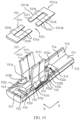
- FIG. 4 schematically shows an explosive view of a partial structure of the electronic device 10 according to this application.
- a flexible display screen 30 includes a display part for displaying image information.
- the flexible display screen 30 is bendable and may be folded under external force.
- the display part of the flexible display screen 30 is unfolded to present the image information to a user.
- the display part may include a first display region 31, a second display region 32, and a third display region 33.
- the first display region 31 and the second display region 32 are arranged corresponding to two frames 40, respectively.
- the third display region 33 may be arranged corresponding to a hinge apparatus 50.
- the display part When the two frames 40 are in a folded state, the display part is in a bent state.
- the first display region 31 and the second display region 32 of the display part may be stacked, and the third display region 33 may be bent into an arc state.
- the electronic device 10 may change an overall size by folding or unfolding and may have a large display area in an unfolded state.
- Electronic components are provided in each of the two frames 40 of the electronic device 10, for example, the electronic components may include but are not limited to a processor, a memory, or a camera module.
- main boards are disposed in the frames 40.
- the electronic components are disposed on the main boards.
- the main board may be a printed circuit board (printed circuit board, PCB).
- FIG. 5 schematically shows a structure of a hinge apparatus 50 according to this application.
- the hinge apparatus 50 of this application includes a shaft cover 51.
- the shaft cover 51 may be located between the two frames 40.
- the shaft cover 51 may cover another structural part on the hinge apparatus 50, so that the electronic device 10 has a trim and aesthetic appearance.
- a position of the shaft cover 51 may remain relatively fixed.
- the two frames 40 when the two frames 40 are in an unfolded state, the two frames 40 may cover the shaft cover 51 so that the shaft cover 51 is a concealed state.
- the two frames 40 are in a folded state, at least part of the shaft cover 51 may be exposed out of the two frames 40 to be in a visible state.
- the shaft cover 51 can provide a mounting base for related structural parts of the hinge apparatus 50.
- the shaft cover 51 may be a strip-shaped structure.
- the frames 40 are respectively disposed on two sides of the shaft cover 51 in a width direction X of the shaft cover 51.
- the shaft cover 51 includes accommodation recess parts 51a.
- the accommodation recess parts 51a of the shaft cover 51 may face the flexible display screen 30.
- a side that is of the shaft cover 51 and that faces the flexible display screen 30 may be provided with the accommodation recess parts 51a.
- a material of the shaft cover 51 may be a metal material such as, but not limited to, stainless steel or titanium alloy.
- the hinge apparatus 50 further includes bases 52.
- the bases 52 may be configured to provide a mounting base for other parts.
- the bases 52 may be detachably connected to the shaft cover 51 in a manner such as, but not limited to, using screws to connect the bases 52 to the shaft cover 51.
- the bases 52 are disposed in the accommodation recess parts 51a of the shaft cover 51.
- the base 52 is located at the side that is of the shaft cover 51 and that faces the flexible display screen 30.
- FIG. 6 schematically shows a partial structure of a hinge apparatus 50 according to this application.
- the base 52 includes relief spaces 52a and first adapter parts 52b.
- the first adapter parts 52b face the relief spaces 52a.
- the base 52 includes a limiting guide track 521 and a synchronous slider 522.
- the limiting guide track 521 is connected to the shaft cover 51.
- the limiting guide track 521 is disposed at a side that is of the synchronous slider 522 and that faces away from the shaft cover 51.
- the synchronous slider 522 is slidably connected to the limiting guide track 521.
- the limiting guide track 521 can form a positional limitation on the synchronous slider 522, so that the synchronous slider 522 is less likely to separate from the limiting guide track 521 and the shaft cover 51.
- the limiting guide track 521 can guide the synchronous slider 522, to ensure accuracy of a movement direction of the synchronous slider 522, so that the synchronous slider 522 is less likely to deviate.
- a movement direction of the synchronous slider 522 may be the same as a length direction Y of the shaft cover 51.
- FIG. 7 schematically shows a partial structure of a hinge apparatus 50 according to this application.
- the limiting guide track 521 shown in FIG. 5 is removed in the structure shown in FIG. 7 .
- FIG. 8 schematically shows a partial structure of a hinge apparatus 50 according to this application.
- the hinge apparatus 50 further includes swing arm assemblies 53.
- the swing arm assemblies 53 each include swing arm bodies 531 and second adapter parts 532.
- the swing arm bodies 531 are connected to the frames 40.
- the swing arm bodies 531 are detachably connected to the frames 40.
- Each swing arm body 531 includes a connection end 531a and a free end 531b.
- connection end 531a of the swing arm body 531 is close to the base 52, and the free end 531b of the swing arm body 531 is away from the base 52.
- the free ends 531b of the swing arm bodies 531 may be configured to be connected to the frames 40.
- At least part of the connection end 531a is located in the relief space 52a of the base 52.
- the second adapter parts 532 are connected to the connection ends 531a of the swing arm bodies 531.
- the second adapter parts 532 are rotatably connected to the first adapter parts 52b.
- the second adapter part 532 is located at a side of the swing arm body 531 in a movement direction of the synchronous slider 522.
- a rotation axis of the second adapter part 532 extends in the length direction Y of the shaft cover 51.
- the second adapter parts 532 are connected to the synchronous slider 522.
- the swing arm bodies 531 rotate relative to the first adapter parts 52b via the second adapter parts 532, to switch between a folded position and an unfolded position.
- the relief spaces 52a of the base 52 may accommodate the swing arm bodies 531, to avoid positional interference between the base 52 and the swing arm bodies 531.
- the swing arm bodies 531 When the swing arm bodies 531 are connected to the frames 40, the swing arm bodies 531 may flip synchronously with the frames 40, so that the frames 40 may rotate relative to the hinge apparatus 50 to be folded.
- the second adapter parts 532 rotate relative to the first adapter parts 52b, the second adapter parts 532 synchronously drive the synchronous slider 522 to move between a first position and a second position.
- the synchronous slider 522 is in the first position.
- the synchronous slider 522 When the swing arm bodies 531 are at the unfolded position, the synchronous slider 522 is in the second position.
- the synchronous slider 522 can realize movement synchronization of the swing arm assemblies 53 on two sides of the shaft cover 51, to ensure movement synchronization of the frames 40 on the two sides of the shaft cover 51, so that consistence of rotation angles of the frames 40 on the two sides during folding and unfolding are ensured, thereby facilitating improvement of stability and smoothness of the flexible display screen 30 during folding or unfolding, and improving convenience as well as experience and satisfaction during use of the electronic device 10.
- the shaft cover 51 can provide a mounting base for the bases 52 and the swing arm assemblies 53.
- the shaft cover 51 can protect the bases 52 and the swing arm assemblies 53.
- Each base 52 includes the synchronous slider 522 and the limiting guide track 521.
- the synchronous slider 522 is slidable relative to the limiting guide track 521.
- the limiting guide track 521 can form a positional limitation on the synchronous slider 522.
- the base 52 further includes relief spaces 52a and first adapter parts 52b. Part of the swing arm body 531 of the swing arm assembly 53 is located in the relief space 52a, to facilitate increasing structural compactness of the hinge apparatus 50.
- the second adapter parts 532 of the swing arm assemblies 53 are rotatably connected to the first adapter parts 52b of the bases 52.
- the second adapter parts 532 are connected to the synchronous slider 522.
- the second adapter parts 532 synchronously drive the synchronous slider 522 to move relative to the limiting guide track 521, so that synchronization between a flipping process of the swing arm bodies 531 and a movement process of the synchronous slider 522 may be achieved, and the synchronous slider 522 can achieve synchronization of flipping movements of the swing arm bodies 531 on two sides of the shaft cover 51, to ensure that the frames 40 connected to the swing arm bodies 531 can rotate synchronously, thereby facilitating improvement of convenience as well as experience and satisfaction during use of the electronic device 10.
- the hinge apparatus 50 includes two bases 52.
- the two bases 52 are spaced apart in the length direction Y of the shaft cover 51.
- the bases 52 may be disposed close to end parts of the shaft cover 51.
- Two swing arm assemblies 53 may be connected to one base 52, and the two swing arm assemblies 53 are spaced apart in the width direction X of the shaft cover 51.
- the two swing arm assemblies 53 may flip synchronously.
- the second adapter parts 532 of the two swing arm assemblies 53 may synchronously drive the synchronous slider 522 to move.
- the swing arm bodies 531 are in the folded position, the free ends 531b of the two swing arm bodies 531 are close to each other.
- the swing arm bodies 531 are in the unfolded position, the free ends 531b of the two swing arm bodies 531 are away from each other.
- one frame 40 may be connected to the two swing arm assemblies 53.
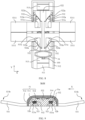
- FIG. 9 schematically shows a cross-sectional structure obtained by cutting in a W-W direction in FIG. 5 .
- the first adapter parts 52b are arc slide ways.
- the first adapter parts 52b are circular-arc-shaped.
- An axial direction of the first adapter part 52b is the same as the length direction Y of the shaft cover 51.
- the axial direction of the first adapter part 52b is the same as the movement direction of the synchronous slider 522.
- the first adapter parts 52b are communicated with the relief spaces 52a.
- the first adapter parts 52b may be observed from the relief spaces 52a.
- the second adapter parts 532 are arc structures.
- the second adapter parts 532 are circular-arc-shaped.
- An axial direction of the second adapter part 532 is the same as the length direction Y of the shaft cover 51. In addition, the axial direction of the second adapter part 532 is the same as the movement direction of the synchronous slider 522.
- the second adapter parts 532 are fitted to the first adapter parts 52b by insertion. At least part of the second adapter part 532 is located in the first adapter part 52b. An axis of the first adapter part 52b is coaxial with an axis of the second adapter part 532. A shape of the first adapter part 52b matches a shape of the second adapter part 532.
- the second adapter parts 532 are entirely located in the first adapter parts 52b.
- most of the second adapter parts 532 are located in the first adapter parts 52b.
- the swing arm bodies 531 are in a folded position, most of the second adapter parts 532 are located outside the first adapter parts 52b.
- the rotatable connection between the first adapter parts 52b of the bases 52 and the second adapter parts 532 of the swing arm assemblies 53 may be implemented without needing to provide additional connecting pieces to connect the first adapter parts 52b and the second adapter parts 532, thereby facilitating reduction of a quantity of parts used, and increasing structural compactness of the hinge apparatus 50.
- the insertion fitting between the first adapter parts 52b and the second adapter parts 532 in arc structures enables the bases 52 to form a positional limitation on the second adapter parts 532, to ensure smoothness of the first adapter parts 52b during rotation relative to the second adapter parts 532 and make the first adapter parts 52b and the second adapter parts 532 less likely to separate.
- the first adapter parts 52b and the second adapter parts 532 are disposed on two sides of the swing arm body 531 in the movement direction of the synchronous slider 522, so that the swing arm body 531 may be rotatably connected to the first adapter parts 52b of the bases 52 via the second adapter parts 532 on the two sides, thereby facilitating improvement of stress equalization of the swing arm body 531, and ensuring smooth rotation of the swing arm body 531.
- the synchronous slider 522 may include first helical surfaces 522a.
- the first helical surfaces 522a are arranged corresponding to the first adapter parts 52b.
- the first helical surfaces 522a may be observed via the first adapter parts 52b in the movement direction of the synchronous slider 522.
- Each first helical surface 522a is located at a side that is of the first adapter part 52b and that faces away from the relief space 52a.
- the second adapter part 532 includes second helical surfaces 532a.
- a top surface that is of the second adapter part 532 and that faces away from the swing arm body 531 may be the second helical surface 532a.
- the first helical surfaces 522a are in contact with the second helical surfaces 532a, so that the second adapter parts 532 may transmit driving force to the synchronous slider 522 in contact regions between the first helical surfaces 522a and the second helical surfaces 532a.
- Helix directions of the first helical surfaces 522a on the two sides of the swing arm body 531 are identical to the movement direction of the synchronous slider 522, and helix directions of the second helical surfaces 532a on the two sides of the swing arm body 531 are identical.
- the first helical surfaces 522a and the second helical surfaces 532a slide relative to each other synchronously, to enable the second adapter parts 532 to drive the synchronous slider 522 to move.
- the swing arm body 531 switches between an unfolded position and a folded position, the first helical surfaces 522a and the second helical surfaces 532a on two sides of the swing arm body 531 remain in a close contact state.
- the second adapter part 532 on one side of the swing arm body 531 pushes the synchronous slider 522, the second adapter part 532 on the other side of the swing arm body 531 releases the synchronous slider 522, to realize movement of the synchronous slider 522, and ensure synchronization between a rotating process of the swing arm body 531 and a movement process of the synchronous slider 522.
- Transmission between the synchronous slider 522 and the swing arm assemblies 53 achieved via the first helical surfaces 552a and the second helical surfaces 532a facilitates lowering possibility of the synchronous slider 522 and the swing arm assembly 53 getting stuck, ensure smooth rotation of the swing arm assemblies 53, and facilitates ensuring synchronization in rotation of the two swing arm assemblies 53 on the two side of the synchronous slider 522.
- the stressed swing arm assembly 53 is not easy to rotate, while when a rotation moment is applied to both the two swing arm assemblies 53, the two swing arm assemblies 53 may synchronously rotate relative to the synchronous slider 522.
- the two swing arm assemblies 53 are connected to the bases 52.
- the two swing arm assemblies 53 are spaced apart in the width direction X of the shaft cover 51.
- a helix direction of the first helical surface 522a corresponding to one swing arm assembly 53 is opposite to a helix direction of the first helical surface 522a corresponding to the other swing arm assembly 53.
- a helix direction of the second helical surface 532a corresponding to one swing arm assembly 53 is opposite to a helix direction of the second helical surface 532a corresponding to the other swing arm assembly 53.
- the swing arm bodies 531 when the synchronous slider 522 is in the first position, the swing arm bodies 531 are in the folded position. When the synchronous slider 522 is in the second position, the swing arm bodies 531 are in the unfolded position. When the swing arm bodies 531 rotate from the folded position to the unfolded position, the synchronous slider 522 moves toward the end part of the shaft cover 51, so that the synchronous slider 522 moves from the first position to the second position. When the swing arm bodies 531 rotate from the unfolded position to the folded position, the synchronous slider 522 moves away from the end part of the shaft cover 51, so that the synchronous slider 522 moves from the second position to the first position.
- the guide recess 522c is disposed at a side that is of the first adapter part 52b and that faces away from a relief space 52a.
- the limiting guide track 521 includes guide parts 521b.
- the guide parts 521b are located in the guide recess 522c.
- a shape of the guide part 521b matches a shape of the guide recess 522c.
- the synchronous slider 522 is rotatably connected to the guide parts 521b.
- the guide parts 521b of the limiting guide track 521 can form a positional limitation on the synchronous slider 522, so that the synchronous slider 522 is less likely to deviate relative to the limiting guide track 521 during movement of the synchronous slider 522 in a length direction Y of a shaft cover 51.
- an inner wall that is of the guide recess 522c and that faces the limiting guide track 521 may be an arc surface
- a surface that is of the guide part 521b and that faces the guide recess 522c may be an arc surface.
- the inner wall that is of the guide recess 522c and that faces the limiting guide track 521 is connected to a first helical surface 522a.
- the two connecting support legs 5211b of the limiting guide member 5211 are located at a same side of the fixed part 5211a in the length direction Y of the shaft cover 51.
- Two limiting guide members 5211 in the base 52, connecting support legs 5211b of one limiting guide member 5211 face connecting support legs 5211b of another limiting guide member 5211.
- the first relief part 521c is formed between the connecting support legs 5211b of one limiting guide member 5211 and the connecting support legs 5211b of another limiting guide member 5211.
- first arc surfaces 521a are provided on the connecting support legs 5211b of the limiting guide members 5211, and the second arc surfaces 522b and the first helical surfaces 522a are provided on the end connection parts 5221.
- the end connection part 5221 may be provided with guide recesses 522c.
- Guide parts 521b are provided on the connecting support legs 5211b of the limiting guide members 5211.
- a length of the end connection part 5221 is less than a length of the connecting support leg 5211b in the length direction Y of the shaft cover 51.
- the shaft cover 51 includes a bottom plate 511, side plates 512, and support bosses 513.
- the bottom plate 511 and the side plates 512 form accommodation recess parts 51a.
- the base 52 is disposed between the two side plates 512 in the width direction X of the shaft cover 51.
- a limiting guide track 521 of the base 52 is disposed at a side that is of the synchronous slider 522 and that faces away from the bottom plate 511.
- the support bosses 513 are disposed on the bottom plate 511.
- the fixed part 5211a of the limiting guide member 5211 is located at a side that is of the support boss 513 and that faces away from the bottom plate 511.
- the fixed part 5211a is connected to the support boss 513.
- the two support bosses 513 are spaced apart in a movement direction of the synchronous slider 522.
- the synchronous slider 522 is disposed between the two support bosses 513.
- the fixed parts 5211a of the limiting guide members 5211 are detachably connected to the support bosses 513.
- the fixed parts 5211a may be connected to the support bosses 513 by using screws.
- the synchronous slider 522 is slidably connected to the shaft cover 51, so that the synchronous slider 522 is slidably connected to the limiting guide track 521, and the synchronous slider 522 is slidably connected to the shaft cover 51, to positionally limit the synchronous slider 522 by the limiting guide track 521 and the shaft cover 51 together, thereby facilitating improvement of stability of the synchronous slider 522 during movement.
- the shaft cover 51 may include ribs 514.
- the ribs 514 are located at a side that is of the synchronous slider 522 and that faces away from the limiting guide track 521.
- the ribs 514 abut against a surface that is of the synchronous slider 522 and that faces away from the limiting guide track 521.
- the synchronous slider 522 is slidably fitted to the ribs 514.
- the limiting guide track 521 and the ribs 514 abut against two sides of the synchronous slider 522.
- a quantity of the ribs 514 may be two.
- the two ribs 514 are spaced apart in the width direction X of the shaft cover 51.
- a surface that is of the rib 514 and that faces the synchronous slider 522 may be an arc surface, to facilitate reduction of a contact area between the rib 514 and the synchronous slider 522, thereby reducing frictional resistance.
- the shaft cover 51 includes the bottom plate 511 and the side plates 512.
- the bottom plate 511 and the side plates 512 form accommodation recess parts 51a.
- the ribs 514 are disposed on the bottom plate 511.
- the limiting guide track 521 is located at a side that is of the synchronous slider 522 and that faces away from the bottom plate 511.
- there may be spacing between the synchronous slider 522 and the side plates 512 to reduce possibility of generating frictional resistance due to contact between the synchronous slider 522 and the side plates 512.
- the side plates 512 are each provided with a relief notch. When the swing arm body 531 is at an unfolded position, the relief notches may accommodate the swing arm bodies 531.
- a surface that is of the swing arm body 531 and that faces away from the shaft cover 51 may be flush with a top surface that is of the side plate 512 and that faces away from the bottom plate 511.
- the top surface that is of the side plate 512 and that faces away from the bottom plate 511, the surface that is of the synchronous slider 522 and that faces away from the bottom plate 511, and a surface that is of the limiting guide member 5211 and that faces away from the bottom plate 511 may all be flush with each other.
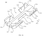
- FIG. 17 schematically shows a structure of a swing arm assembly 53 according to this application.
- FIG. 18 schematically shows an exploded structure of a swing arm assembly 53 according to this application.
- Each swing arm body 531 includes two connecting arms 5311.
- the two connecting arms 5311 are disposed side by side in a movement direction of the synchronous slider 522.
- the two connecting arms 5311 are slidably connected to each other.
- the swing arm assembly 53 further includes elastic members 533.
- Each elastic member 533 is disposed between the two connecting arms 5311.
- a second adapter part 532 may be correspondingly provided on a side of each connecting arm 5311.
- the elastic members 533 are disposed corresponding to the second adapter parts 532.
- Each elastic member 533 can provide force for the two connecting arms 5311, so that after the swing arm assemblies 53 are fitted to the base 52, a close contact state between the first helical surfaces 522a of the synchronous slider 522 and the second helical surfaces 532a of the second adapter parts 532 may be maintained stably, to reduce possibility of gaps between the first helical surfaces 522a and the second helical surfaces 532a, thereby effectively ensuring rotation synchronization of the swing arm assemblies 53.
- an accommodation space 531d is formed between the two connecting arms 5311, and the elastic member 533 is disposed in the accommodation space 531d.
- the elastic member 533 may be a helical spring.
- An axis of the elastic member 533 may coincide with an axis of the second adapter part 532.
- the elastic members 533 may be in a compressed state.
- one of the connecting support arms 5311 includes an insertion block 5311a
- the other connecting support arm 5311 includes an insertion slot 5311b.
- the insertion block 5311a is inserted into the insertion slot 5311b in a movement direction of the synchronous slider 522.
- the two connecting arms 5311 are slidably connected to each other via the insertion block 5311a and the insertion slot 5311b, and the two connecting arms 5311 may transmit force through the insertion block 5311a, to ensure that the two connecting arms 5311 maintain rotation synchronization.
- the connecting arm 5311 and the second adapter part 532 connected to the connecting arm 5311 are an integrally formed structure.
- an assembly manner may be, but is not limited to, placing the synchronous slider 522 in the shaft cover 51.
- the synchronous slider 522 includes the first helical surfaces 522a and the second arc surfaces 522b. Then, the elastic member 533 is placed into the accommodation space 531d formed between the two connecting arms 5311.
- the two connecting arms 5311 of the swing arm assembly 53 are connected by insertion via the insertion block 5311a and the insertion slot 5311b.
- the second adapter parts 532 of the swing arm assembly 53 are placed on the synchronous slider 522, and fourth arc surfaces 532c of the second adapter parts 532 are in close contact with second arc surfaces 522b of the synchronous slider 522, and under an action of the elastic members 533, the second helical surfaces 532a of the second adapter parts 532 are in close contact with the first helical surfaces 522a of the synchronous slider 522.
- the limiting guide members 5211 are placed at a top of the synchronous slider 522.
- the first arc surfaces 521a on the connecting support legs 5211b of the limiting guide members 5211 are in close contact with the third arc surfaces 532b of the second adapter parts 532, and the guide parts 521b on the connecting support legs 5211b match the guide recesses 522c of the end connection parts 5221.
- the fixed parts 5211a of the limiting guide members 5211 are connected to the support bosses 513 of the shaft cover 51, to ensure that the second adapter parts 532 is compressed by the connecting support legs 5211b and the end connection parts 5221.
- the two connecting arms 5311 of the swing arm assembly 53 may be connected to frames 40. After the two connecting arms 5311 are connected to the frames 40, positions of the two connecting arms 5311 are relatively fixed, and do not change anymore.
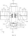
- FIG. 19 and FIG. 20 each schematically show a partial structure of a hinge apparatus 50 according to this application.
- the hinge apparatus 50 further includes elastic damping members 54.
- the elastic damping member 54 is disposed on at least one side of the synchronous slider 522 in the movement direction of the synchronous slider 522.
- the swing arm assemblies 53 rotates relative to the base 52, and during the swing arm assemblies 53 driving the synchronous slider 522 to move to switch between a first position and a second position, the synchronous slider 522 may cause the elastic damping members 54 to deform. Elastic force of the elastic damping member 54 may apply reaction force on the synchronous slider 522, to provide damping force, to enable the synchronous slider 522 to maintain a smooth and slow status during a movement process. In addition, force is transmitted through the synchronous slider 522, to increase rotate resistance of the swing arm assemblies 53, so that a large rotation moment needs to be applied to the swing arm assemblies 53 to drive the swing arm assemblies 53 to rotate, and the swing arm assemblies 53 may maintain a smooth and slow status during a rotating process. After the frames 40 are connected to the swing arm assemblies 53, the frames 40 may maintain a smooth and slow status during a rotating process, thereby facilitating improvement of a hand feel during folding or unfolding the frames 40.
- each elastic damping member 54 is connected to the synchronous slider 522, the other end of the elastic damping member 54 is connected to the shaft cover 51 or the limiting guide track 521.
- the elastic damping member 54 is disposed on a side of an end part that is of the synchronous slider 522 and that faces away from the shaft cover 51.
- the synchronous slider 522 includes end connection parts 5221 and an intermediate connection part 5222.
- the elastic damping members 54 are connected to the end connection parts 5221.
- the synchronous slider 522 includes first helical surfaces 522a
- the second adapter parts 532 of the swing arm assembly 53 include second helical surfaces 532a.
- the elastic damping members 54 apply force on the synchronous slider 522. This may increase frictional resistance between the first helical surfaces 522a and the second helical surfaces 532a, thereby increasing rotation resistance of the swing arm assembly 53.
- the elastic damping member 54 may include an annular body 541.
- the annular body 541 includes elastic arms 5411 and support arms 5412.
- Two elastic arms 5411 are spaced apart in a movement direction of the synchronous slider 522.
- the support arms 5412 are connected to the two elastic arms 5411.
- the two support arms 5412 are spaced apart in a width direction X of the shaft cover 51.
- the elastic arms 5411 and the support arms 5412 are disposed alternately.
- One of the elastic arms 5411 is connected to the synchronous slider 522, and the other elastic arm 5411 is connected to at least one of the shaft cover 51 and the limiting guide track 521.
- the synchronous slider 522 moving and switching between a first position and a second position, the synchronous slider 522 may cause the elastic arms 5411 to deform.
- the elastic arm 5411 may be a plate-like structure.
- the support arm 5412 may be a plate-like structure.
- the elastic damping member 54 is disposed on a side of an end part that is of the synchronous slider 522 and that faces away from the shaft cover 51.
- the synchronous slider 522 may apply force on the elastic arms 5411, to cause the two elastic arms 5411 of the annular body 541 to move away from each other.
- the synchronous slider 522 may apply force on the elastic arms 5411, to cause the two elastic arms 5411 of the annular body 541 to move toward each other.
- the elastic damping member 54 may further include connecting support arms 542.
- the elastic arms 5411 are connected to the connecting support arms 542.
- One of the connecting support arms 542 on the elastic arm 5411 is connected to the synchronous slider 522, and the other connecting support arm 542 on the elastic arm 5411 is connected to at least one of the shaft cover 51 and the limiting guide track 521.
- the synchronous slider 522 may be provided with connecting holes 100, and the connecting support arms 542 may be inserted into connecting holes 100, to enable the synchronous slider 522 to be connected to the elastic damping members 54, thereby facilitating reduction of a quantity of parts used to implement connection between the synchronous slider 522 and the elastic damping members 54 and reduction of assembly complexity of the synchronous slider 522 and the elastic damping members 54.
- the connecting support arms 542 on the elastic arms 5411 are connected to the shaft cover 51.
- the shaft cover 51 may be provided with the connecting holes 100, and the connecting support arms 542 may be inserted into the connecting holes 100, to enable the shaft cover 51 to be connected to the elastic damping members 54, thereby facilitating reduction of a quantity of parts used to implement connection between the shaft cover 51 and the elastic damping members 54 and reduction of assembly complexity of the shaft cover 51 and the elastic damping members 54.
- the connecting support arms 542 of the elastic arms 5411 are connected to the limiting guide track 521.
- the limiting guide track 521 may be provided with connecting holes 100, and the connecting support arms 542 may be inserted into the connecting holes 100, to enable the limiting guide track 521 to be connected to the elastic damping members 54, thereby facilitating reduction of a quantity of parts used to implement connection between the limiting guide track 521 and the elastic damping members 54 and reduction of assembly complexity of the limiting guide track 521 and the elastic damping members 54.
- the limiting guide track 521 includes limiting guide members 5211.
- the connecting support arms 542 may be connected to the fixed parts 5211a of the limiting guide members 5211.
Landscapes
- Engineering & Computer Science (AREA)
- Theoretical Computer Science (AREA)
- General Engineering & Computer Science (AREA)
- Computer Hardware Design (AREA)
- Signal Processing (AREA)
- Physics & Mathematics (AREA)
- General Physics & Mathematics (AREA)
- Human Computer Interaction (AREA)
- Microelectronics & Electronic Packaging (AREA)
- Mechanical Engineering (AREA)
- Telephone Set Structure (AREA)
Claims (15)
- Eine Scharnierapparatur, umfassend:eine Wellenabdeckung, umfassend Aufnahmeeinlassbereiche;Basen, angeordnet in den Aufnahmeeinlassbereichen, wobei jede Basis Entlastungsräume und erste Adapterteile umfasst, die ersten Adapterteile den Entlastungsräumen zugewandt sind, die Basis einen synchronen Schieber und eine Begrenzungsführungsschiene umfasst, die Begrenzungsführungsschiene mit der Wellenabdeckung verbunden ist, die Begrenzungsführungsschiene an einer Seite angeordnet ist, die dem synchronen Schieber zugewandt ist und von der Wellenabdeckung wegzeigt, und der synchrone Schieber gleitend mit der Begrenzungsführungsschiene verbunden ist; undSchwenkarmbaugruppen, die jeweils Schwenkarmkörper und zweite Adapterteile umfassen, wobei jeder Schwenkarmkörper ein Verbindungsende und ein freies Ende umfasst, das Verbindungsende nahe der Basis ist, das freie Ende von der Basis entfernt ist, mindestens ein Teil des Verbindungsendes sich im Entlastungsraum befindet, die zweiten Adapterteile mit den Verbindungsenden verbunden sind, die zweiten Adapterteile drehbar mit den ersten Adapterteilen verbunden sind, die zweiten Adapterteile mit dem synchronen Schieber verbunden sind, die Schwenkarmkörper relativ zu den ersten Adapterteilen über die zweiten Adapterteile rotieren, um zwischen einer gefalteten Position und einer ungefalteten Position zu wechseln, und die zweiten Adapterteile den synchronen Schieber synchron antreiben, um sich zwischen einer ersten Position und einer zweiten Position zu bewegen; undder synchrone Schieber umfasst erste Schraubenflächen, die ersten Schraubenflächen sind entsprechend den ersten Adapterteilen angeordnet, jede erste Schraubenfläche befindet sich an einer Seite des ersten Adapterteils, die vom Entlastungsraum wegzeigt, jedes zweite Adapterteil umfasst eine zweite Schraubenfläche, die ersten Schraubenflächen stehen in Kontakt mit den zweiten Schraubenflächen, die Schraubenrichtungen der ersten Schraubenflächen auf den beiden Seiten des Schwenkarmkörpers sind identisch, die Schraubenrichtungen der zweiten Schraubenflächen auf den beiden Seiten des Schwenkarmkörpers sind identisch, wenn die zweiten Adapterteile entgegengesetzt zu den ersten Adapterteilen rotieren, gleiten die ersten Schraubenflächen und die zweiten Schraubenflächen synchron relativ zueinander, um die zweiten Adapterteile zu ermöglichen, den synchronen Schieber zu bewegen.
- Die Scharnierapparatur gemäß Anspruch 1, wobei die ersten Adapterteile bogenförmige Gleitwege sind, eine axiale Richtung der ersten Adapterteile dieselbe ist wie eine Bewegungsrichtung des synchronen Schiebers, die ersten Adapterteile mit den Entlastungsräumen kommunizieren, die zweiten Adapterteile bogenförmige Strukturen sind, mindestens ein Teil jedes zweiten Adapterteils sich im ersten Adapterteil befindet, eine Achse des ersten Adapterteils koaxial mit einer Achse des zweiten Adapterteils ist, und eine Form des ersten Adapterteils mit einer Form des zweiten Adapterteils übereinstimmt.
- Das Scharniergerät gemäß Anspruch 2, wobei in Bewegungsrichtung des synchronen Schiebers jede der beiden Seiten des Schwenkarmkörpers mit dem ersten Adapterteil und dem zweiten Adapterteil versehen ist.
- Das Scharniergerät gemäß Anspruch 3, wobei die Begrenzungsführungsschiene erste Bogenflächen umfasst, der synchrone Schieber zweite Bogenflächen umfasst, zwischen den ersten Bogenflächen und den zweiten Bogenflächen Bogenrutschwege gebildet werden, die zweiten Adapterteile dritte Bogenflächen und vierte Bogenflächen umfassen, die ersten Bogenflächen mit den dritten Bogenflächen in Kontakt stehen und die zweiten Bogenflächen mit den vierten Bogenflächen in Kontakt stehen, die ersten Schraubenflächen mit den zweiten Bogenflächen verbunden sind und die dritten Bogenflächen und die vierten Bogenflächen durch die zweiten Bogenflächen verbunden sind.
- Das Scharniergerät gemäß Anspruch 4, wobei der synchrone Schieber Führungsvertiefungen umfasst, die Führungsvertiefungen der Begrenzungsführungsschiene zugewandt sind, die Führungsvertiefungen mit den ersten Adapterteilen kommunizieren, die Begrenzungsführungsschiene Führungsbauteile umfasst, die Führungsbauteile in den Führungsvertiefungen angeordnet sind und die Formen der Führungsbauteile den Formen der Führungsvertiefungen entsprechen.
- Das Scharniergerät gemäß Anspruch 5, wobei eine Innenwand jeder Führungsvertiefung bogenförmig ist, eine Oberfläche jedes Führungsbauteils, die der Führungsvertiefung zugewandt ist, bogenförmig ist und eine Achse der Führungsvertiefung koaxial mit einer Achse des Führungsbauteils ist.
- Das Scharniergerät gemäß Anspruch 2, wobei die Begrenzungsführungsschiene zwei Begrenzungsführungselemente umfasst, die beiden Begrenzungsführungselemente in Bewegungsrichtung des synchronen Schiebers beabstandet sind, um einen ersten Entlastungsteil zwischen den beiden Begrenzungsführungselementen zu bilden, der synchrone Schieber zwei Endverbindungsteile und einen mittleren Verbindungsteil umfasst, die beiden Endverbindungsteile in Bewegungsrichtung des synchronen Schiebers beabstandet sind, der mittlere Verbindungsteil die beiden Endverbindungsteile verbindet, der synchrone Schieber zweite Entlastungsteile umfasst, die sich an zwei Seiten des mittleren Verbindungsteils befinden, der erste Entlastungsteil und die zweiten Entlastungsteile die Entlastungsräume bilden, die Endverbindungsteile gleitend mit den entsprechenden Begrenzungsführungselementen verbunden sind und die ersten Adapterteile zwischen den Endverbindungsteilen und den Begrenzungsführungselementen angeordnet sind.
- Das Scharniergerät gemäß Anspruch 7, wobei jedes Begrenzungsführungselement einen festen Teil und zwei verbindende Stützbeine umfasst, der feste Teil die beiden verbindenden Stützbeine verbindet, der feste Teil mit der Wellenabdeckung verbunden ist, die Endverbindungsteile gleitend mit den entsprechenden verbindenden Stützbeinen verbunden sind und die ersten Adapterteile zwischen den Endverbindungsteilen und den verbindenden Stützbeinen angeordnet sind.
- Die Scharnierapparatur gemäß Anspruch 8, wobei die Wellenabdeckung eine Bodenplatte, Seitenplatten und Stützvorsprünge umfasst, die Bodenplatte und die Seitenplatten die Aufnahmeaussparungen bilden, die Stützvorsprünge auf der Bodenplatte angeordnet sind, die festen Teile mit den Stützvorsprüngen verbunden sind, die beiden Stützvorsprünge in Bewegungsrichtung des synchronen Schiebers beabstandet sind und der synchrone Schieber zwischen den beiden Stützvorsprüngen angeordnet ist.
- Die Scharnierapparatur gemäß Anspruch 7, wobei jeder Schwenkarmkörper zwei Verbindungsstützarme umfasst, die beiden Verbindungsstützarme parallel in Bewegungsrichtung des synchronen Schiebers angeordnet und gleitend miteinander verbunden sind, jede Schwenkarmbaugruppe ferner elastische Elemente umfasst, jedes elastische Element zwischen den beiden Verbindungsstützarmen angeordnet ist und die elastischen Elemente den zweiten Adapterteilen entsprechen;
wobei einer der Verbindungsstützarme einen Einsteckblock umfasst, der andere Verbindungsstützarm einen Einsteckschlitz umfasst und der Einsteckblock in Bewegungsrichtung des synchronen Schiebers in den Einsteckschlitz eingesetzt ist. - Die Scharnierapparatur gemäß einem der Ansprüche 1 bis 10, wobei jeder Schwenkarmkörper Begrenzungsflächen umfasst, die den zweiten Adapterteilen zugewandt sind, wobei sich mindestens ein Teil jeder Begrenzungsfläche im Entlastungsraum befindet und Flächen der Begrenzungsführungsschiene, die den Entlastungsräumen zugewandt sind, in Bewegungsrichtung des synchronen Schiebers an den Begrenzungsflächen anliegen.
- Die Scharnierapparatur gemäß einem der Ansprüche 1 bis 10, wobei die Scharnierapparatur ferner elastische Dämpfungselemente umfasst und das elastische Dämpfungselement auf mindestens einer Seite des synchronen Schiebers in Bewegungsrichtung des synchronen Schiebers angeordnet ist;wobei das elastische Dämpfungselement einen ringförmigen Körper umfasst, wobei der ringförmige Körper elastische Arme und Stützarme umfasst, die beiden elastischen Arme beabstandet sind, die Stützarme mit den beiden elastischen Armen verbunden sind, die elastischen Arme und die Stützarme abwechselnd angeordnet sind, einer der elastischen Arme mit dem synchronen Schieber verbunden ist und der andere elastische Arm mit mindestens einem der Wellenabdeckung und der Begrenzungsführungsschiene verbunden ist;wobei das elastische Dämpfungselement ferner Verbindungsstützarme umfasst, wobei die elastischen Arme mit den Verbindungsstützarmen verbunden sind, einer der Verbindungsstützarme an den elastischen Armen mit dem synchronen Schieber verbunden ist und der andere Verbindungsstützarm an den elastischen Armen mit mindestens einem der Wellenabdeckung und der Begrenzungsführungsschiene verbunden ist;wobei der elastische Arm, der Stützarm und der Verbindungsstützarm eine integrale Struktur bilden.
- Die Scharnierapparatur gemäß einem der Ansprüche 1 bis 10, wobei die synchronen Schieber gleitend mit der Wellenabdeckung verbunden sind;
wobei die Wellenabdeckung Rippen umfasst, wobei die Rippen sich auf einer Seite befinden, die dem synchronen Schieber zugewandt ist und die von der begrenzenden Führungsschiene weg zeigt, die Rippen an einer Oberfläche anliegen, die dem synchronen Schieber zugewandt ist und die von der begrenzenden Führungsschiene weg zeigt, und der synchrone Schieber gleitend an die Rippen angepasst ist. - Die Scharnierapparatur gemäß Anspruch 13, wobei die Wellenabdeckung eine Bodenplatte und Seitenplatten umfasst, die Bodenplatte und die Seitenplatten bilden die Aufnahmevertiefungsteile, die Rippen sind auf der Bodenplatte ausgebildet, und die begrenzende Führungsschiene befindet sich auf einer Seite, die dem synchronen Schieber zugewandt ist und die von der Bodenplatte weg zeigt;
wobei jede Seitenplatte mit Entlastungsausschnitten versehen ist, die Schwenkarmkörper sich in der ausgeklappten Position befinden und die Entlastungsausschnitte die Schwenkarmkörper aufnehmen. - Ein elektronisches Gerät, umfassend die Scharnierapparatur gemäß einem der Ansprüche 1 bis 14.
Applications Claiming Priority (2)
| Application Number | Priority Date | Filing Date | Title |
|---|---|---|---|
| CN202211620764.1A CN115614373B (zh) | 2022-12-16 | 2022-12-16 | 铰链装置以及电子设备 |
| PCT/CN2023/112979 WO2024124929A1 (zh) | 2022-12-16 | 2023-08-14 | 铰链装置以及电子设备 |
Publications (3)
| Publication Number | Publication Date |
|---|---|
| EP4411155A1 EP4411155A1 (de) | 2024-08-07 |
| EP4411155A4 EP4411155A4 (de) | 2024-10-23 |
| EP4411155B1 true EP4411155B1 (de) | 2025-06-25 |
Family
ID=84880242
Family Applications (1)
| Application Number | Title | Priority Date | Filing Date |
|---|---|---|---|
| EP23821112.2A Active EP4411155B1 (de) | 2022-12-16 | 2023-08-14 | Scharniervorrichtung und elektronische vorrichtung |
Country Status (4)
| Country | Link |
|---|---|
| US (1) | US12530056B2 (de) |
| EP (1) | EP4411155B1 (de) |
| CN (1) | CN115614373B (de) |
| WO (1) | WO2024124929A1 (de) |
Families Citing this family (7)
| Publication number | Priority date | Publication date | Assignee | Title |
|---|---|---|---|---|
| US12455596B2 (en) * | 2022-03-31 | 2025-10-28 | Syncmold Enterprise Corp. | Foldable electronic device |
| US12457281B2 (en) * | 2022-06-28 | 2025-10-28 | Syncmold Enterprise Corp. | Foldable electronic device |
| CN115614373B (zh) * | 2022-12-16 | 2023-05-16 | 荣耀终端有限公司 | 铰链装置以及电子设备 |
| CN117145857B (zh) * | 2023-04-03 | 2024-07-02 | 荣耀终端有限公司 | 铰链装置以及电子设备 |
| CN116950986A (zh) * | 2023-06-26 | 2023-10-27 | 维沃移动通信有限公司 | 铰链机构和电子设备 |
| CN116886804A (zh) * | 2023-08-09 | 2023-10-13 | 维沃移动通信有限公司 | 铰链组件及电子设备 |
| CN118855844B (zh) * | 2024-07-03 | 2025-11-18 | 维沃移动通信有限公司 | 铰链机构和电子设备 |
Family Cites Families (15)
| Publication number | Priority date | Publication date | Assignee | Title |
|---|---|---|---|---|
| TWI529314B (zh) | 2013-07-18 | 2016-04-11 | 仁寶電腦工業股份有限公司 | 樞軸結構 |
| TWI540954B (zh) | 2013-11-29 | 2016-07-01 | 緯創資通股份有限公司 | 具有支撐機構的電子裝置 |
| CN203717618U (zh) | 2014-02-12 | 2014-07-16 | 连鋐科技股份有限公司 | 双轴同动双包枢轴器 |
| KR102630498B1 (ko) * | 2016-08-12 | 2024-01-31 | 삼성전자주식회사 | 플렉서블 디스플레이를 포함하는 전자 장치 |
| CN106969025A (zh) | 2017-02-17 | 2017-07-21 | 联想(北京)有限公司 | 双转轴结构及电子设备 |
| TWM551804U (zh) * | 2017-06-08 | 2017-11-11 | First Dome Corp | 鉸鏈及具有該鉸鏈的折疊式電子裝置 |
| US11093008B2 (en) * | 2019-09-26 | 2021-08-17 | Dell Products L.P. | Synchronized dual shaft expandable hinge |
| US10928864B1 (en) * | 2019-09-26 | 2021-02-23 | Dell Products L.P. | Synchronized dual shaft expandable hinge |
| CN114060398A (zh) * | 2020-08-07 | 2022-02-18 | 华为技术有限公司 | 铰链机构及折叠屏设备 |
| CN217381267U (zh) | 2021-12-24 | 2022-09-06 | 深圳荣耀智能机器有限公司 | 铰链以及电子设备 |
| CN114658753B (zh) * | 2022-04-15 | 2023-02-03 | 维沃移动通信有限公司 | 铰链机构和电子设备 |
| CN114885054B (zh) * | 2022-07-01 | 2022-11-25 | 荣耀终端有限公司 | 折叠机构及折叠电子设备 |
| CN115325016B (zh) * | 2022-07-21 | 2023-07-07 | 荣耀终端有限公司 | 一种摆臂组件、转轴机构和电子设备 |
| CN115405615B (zh) * | 2022-09-13 | 2024-09-03 | 维沃移动通信有限公司 | 铰链机构和电子设备 |
| CN115614373B (zh) | 2022-12-16 | 2023-05-16 | 荣耀终端有限公司 | 铰链装置以及电子设备 |
-
2022
- 2022-12-16 CN CN202211620764.1A patent/CN115614373B/zh active Active
-
2023
- 2023-08-14 WO PCT/CN2023/112979 patent/WO2024124929A1/zh not_active Ceased
- 2023-08-14 US US18/576,916 patent/US12530056B2/en active Active
- 2023-08-14 EP EP23821112.2A patent/EP4411155B1/de active Active
Also Published As
| Publication number | Publication date |
|---|---|
| US12530056B2 (en) | 2026-01-20 |
| WO2024124929A1 (zh) | 2024-06-20 |
| EP4411155A1 (de) | 2024-08-07 |
| CN115614373A (zh) | 2023-01-17 |
| US20250044841A1 (en) | 2025-02-06 |
| CN115614373B (zh) | 2023-05-16 |
| EP4411155A4 (de) | 2024-10-23 |
Similar Documents
| Publication | Publication Date | Title |
|---|---|---|
| EP4411155B1 (de) | Scharniervorrichtung und elektronische vorrichtung | |
| US11188120B2 (en) | Foldable electronic device | |
| EP3917122B1 (de) | Elektronische vorrichtung mit scharnierstruktur | |
| US11726532B2 (en) | Hinge module including detent structure and foldable electronic device including the hinge module | |
| US11528352B1 (en) | Hinged electronic device with displacement altering hinge and corresponding systems | |
| CN111770223B (zh) | 同步装置、可折叠壳体组件及可折叠电子设备 | |
| JP6397195B2 (ja) | 二軸ヒンジ装置 | |
| US20250362719A1 (en) | Hinge apparatus and electronic device | |
| US20140340829A1 (en) | Electronic device | |
| CN113741622B (zh) | 电子设备 | |
| KR102375542B1 (ko) | 전개 가능한 커넥터 모듈을 포함하는 전자 장치 | |
| EP4496299A1 (de) | Drehwellenvorrichtung und klappbildschirmvorrichtung | |
| US20220197346A1 (en) | Hinge module and electronic device including the same | |
| CN111601484B (zh) | 同步装置、可折叠壳体组件及可折叠电子设备 | |
| JP6793234B1 (ja) | 携帯用情報機器 | |
| US12510938B2 (en) | Hinge device of portable terminal having foldable structure | |
| CN211429360U (zh) | 电子设备 | |
| WO2025097887A1 (zh) | 转轴机构和电子设备 | |
| CN117646759B (zh) | 铰链机构及电子设备 | |
| CN120140344A (zh) | 折叠装置、壳体组件和电子设备 | |
| EP4692576A1 (de) | Drehwellenmechanismus und elektronische vorrichtung | |
| CN120926178A (zh) | 折叠装置、壳体组件和电子设备 | |
| EP4654176A1 (de) | Elektronische vorrichtung | |
| CN115523221A (zh) | 同步旋转机构以及电子设备 | |
| CN120769441A (zh) | 折叠装置、壳体组件和电子设备 |
Legal Events
| Date | Code | Title | Description |
|---|---|---|---|
| STAA | Information on the status of an ep patent application or granted ep patent |
Free format text: STATUS: UNKNOWN |
|
| STAA | Information on the status of an ep patent application or granted ep patent |
Free format text: STATUS: THE INTERNATIONAL PUBLICATION HAS BEEN MADE |
|
| PUAI | Public reference made under article 153(3) epc to a published international application that has entered the european phase |
Free format text: ORIGINAL CODE: 0009012 |
|
| STAA | Information on the status of an ep patent application or granted ep patent |
Free format text: STATUS: REQUEST FOR EXAMINATION WAS MADE |
|
| 17P | Request for examination filed |
Effective date: 20231219 |
|
| AK | Designated contracting states |
Kind code of ref document: A1 Designated state(s): AL AT BE BG CH CY CZ DE DK EE ES FI FR GB GR HR HU IE IS IT LI LT LU LV MC ME MK MT NL NO PL PT RO RS SE SI SK SM TR |
|
| A4 | Supplementary search report drawn up and despatched |
Effective date: 20240923 |
|
| RIC1 | Information provided on ipc code assigned before grant |
Ipc: G06F 1/16 20060101ALI20240917BHEP Ipc: H05K 5/02 20060101ALI20240917BHEP Ipc: H04M 1/02 20060101ALI20240917BHEP Ipc: G09F 9/30 20060101ALI20240917BHEP Ipc: F16C 11/12 20060101ALI20240917BHEP Ipc: F16C 11/04 20060101AFI20240917BHEP |
|
| GRAP | Despatch of communication of intention to grant a patent |
Free format text: ORIGINAL CODE: EPIDOSNIGR1 |
|
| STAA | Information on the status of an ep patent application or granted ep patent |
Free format text: STATUS: GRANT OF PATENT IS INTENDED |
|
| DAV | Request for validation of the european patent (deleted) | ||
| DAX | Request for extension of the european patent (deleted) | ||
| INTG | Intention to grant announced |
Effective date: 20250122 |
|
| GRAS | Grant fee paid |
Free format text: ORIGINAL CODE: EPIDOSNIGR3 |
|
| GRAA | (expected) grant |
Free format text: ORIGINAL CODE: 0009210 |
|
| STAA | Information on the status of an ep patent application or granted ep patent |
Free format text: STATUS: THE PATENT HAS BEEN GRANTED |
|
| AK | Designated contracting states |
Kind code of ref document: B1 Designated state(s): AL AT BE BG CH CY CZ DE DK EE ES FI FR GB GR HR HU IE IS IT LI LT LU LV MC ME MK MT NL NO PL PT RO RS SE SI SK SM TR |
|
| REG | Reference to a national code |
Ref country code: GB Ref legal event code: FG4D |
|
| REG | Reference to a national code |
Ref country code: CH Ref legal event code: EP |
|
| REG | Reference to a national code |
Ref country code: CH Ref legal event code: EP |
|
| REG | Reference to a national code |
Ref country code: IE Ref legal event code: FG4D |
|
| REG | Reference to a national code |
Ref country code: DE Ref legal event code: R096 Ref document number: 602023004360 Country of ref document: DE |
|
| REG | Reference to a national code |
Ref country code: NL Ref legal event code: FP |
|
| PG25 | Lapsed in a contracting state [announced via postgrant information from national office to epo] |
Ref country code: FI Free format text: LAPSE BECAUSE OF FAILURE TO SUBMIT A TRANSLATION OF THE DESCRIPTION OR TO PAY THE FEE WITHIN THE PRESCRIBED TIME-LIMIT Effective date: 20250625 |
|
| PGFP | Annual fee paid to national office [announced via postgrant information from national office to epo] |
Ref country code: DE Payment date: 20250708 Year of fee payment: 3 |
|
| REG | Reference to a national code |
Ref country code: LT Ref legal event code: MG9D |
|
| PG25 | Lapsed in a contracting state [announced via postgrant information from national office to epo] |
Ref country code: NO Free format text: LAPSE BECAUSE OF FAILURE TO SUBMIT A TRANSLATION OF THE DESCRIPTION OR TO PAY THE FEE WITHIN THE PRESCRIBED TIME-LIMIT Effective date: 20250925 Ref country code: GR Free format text: LAPSE BECAUSE OF FAILURE TO SUBMIT A TRANSLATION OF THE DESCRIPTION OR TO PAY THE FEE WITHIN THE PRESCRIBED TIME-LIMIT Effective date: 20250926 |
|
| PG25 | Lapsed in a contracting state [announced via postgrant information from national office to epo] |
Ref country code: BG Free format text: LAPSE BECAUSE OF FAILURE TO SUBMIT A TRANSLATION OF THE DESCRIPTION OR TO PAY THE FEE WITHIN THE PRESCRIBED TIME-LIMIT Effective date: 20250625 |
|
| PG25 | Lapsed in a contracting state [announced via postgrant information from national office to epo] |
Ref country code: HR Free format text: LAPSE BECAUSE OF FAILURE TO SUBMIT A TRANSLATION OF THE DESCRIPTION OR TO PAY THE FEE WITHIN THE PRESCRIBED TIME-LIMIT Effective date: 20250625 |
|
| PGFP | Annual fee paid to national office [announced via postgrant information from national office to epo] |
Ref country code: AT Payment date: 20251020 Year of fee payment: 3 |
|
| PG25 | Lapsed in a contracting state [announced via postgrant information from national office to epo] |
Ref country code: RS Free format text: LAPSE BECAUSE OF FAILURE TO SUBMIT A TRANSLATION OF THE DESCRIPTION OR TO PAY THE FEE WITHIN THE PRESCRIBED TIME-LIMIT Effective date: 20250925 |
|
| PG25 | Lapsed in a contracting state [announced via postgrant information from national office to epo] |
Ref country code: LV Free format text: LAPSE BECAUSE OF FAILURE TO SUBMIT A TRANSLATION OF THE DESCRIPTION OR TO PAY THE FEE WITHIN THE PRESCRIBED TIME-LIMIT Effective date: 20250625 |
|
| PG25 | Lapsed in a contracting state [announced via postgrant information from national office to epo] |
Ref country code: PT Free format text: LAPSE BECAUSE OF FAILURE TO SUBMIT A TRANSLATION OF THE DESCRIPTION OR TO PAY THE FEE WITHIN THE PRESCRIBED TIME-LIMIT Effective date: 20251027 |
|
| REG | Reference to a national code |
Ref country code: AT Ref legal event code: MK05 Ref document number: 1806702 Country of ref document: AT Kind code of ref document: T Effective date: 20250625 |
|
| PG25 | Lapsed in a contracting state [announced via postgrant information from national office to epo] |
Ref country code: IS Free format text: LAPSE BECAUSE OF FAILURE TO SUBMIT A TRANSLATION OF THE DESCRIPTION OR TO PAY THE FEE WITHIN THE PRESCRIBED TIME-LIMIT Effective date: 20251025 |
|
| PG25 | Lapsed in a contracting state [announced via postgrant information from national office to epo] |
Ref country code: SM Free format text: LAPSE BECAUSE OF FAILURE TO SUBMIT A TRANSLATION OF THE DESCRIPTION OR TO PAY THE FEE WITHIN THE PRESCRIBED TIME-LIMIT Effective date: 20250625 Ref country code: AT Free format text: LAPSE BECAUSE OF FAILURE TO SUBMIT A TRANSLATION OF THE DESCRIPTION OR TO PAY THE FEE WITHIN THE PRESCRIBED TIME-LIMIT Effective date: 20250625 |
|
| PG25 | Lapsed in a contracting state [announced via postgrant information from national office to epo] |
Ref country code: CZ Free format text: LAPSE BECAUSE OF FAILURE TO SUBMIT A TRANSLATION OF THE DESCRIPTION OR TO PAY THE FEE WITHIN THE PRESCRIBED TIME-LIMIT Effective date: 20250625 |
|
| PG25 | Lapsed in a contracting state [announced via postgrant information from national office to epo] |
Ref country code: PL Free format text: LAPSE BECAUSE OF FAILURE TO SUBMIT A TRANSLATION OF THE DESCRIPTION OR TO PAY THE FEE WITHIN THE PRESCRIBED TIME-LIMIT Effective date: 20250625 |
|
| PG25 | Lapsed in a contracting state [announced via postgrant information from national office to epo] |
Ref country code: EE Free format text: LAPSE BECAUSE OF FAILURE TO SUBMIT A TRANSLATION OF THE DESCRIPTION OR TO PAY THE FEE WITHIN THE PRESCRIBED TIME-LIMIT Effective date: 20250625 |
|
| PG25 | Lapsed in a contracting state [announced via postgrant information from national office to epo] |
Ref country code: SK Free format text: LAPSE BECAUSE OF FAILURE TO SUBMIT A TRANSLATION OF THE DESCRIPTION OR TO PAY THE FEE WITHIN THE PRESCRIBED TIME-LIMIT Effective date: 20250625 |
|
| PG25 | Lapsed in a contracting state [announced via postgrant information from national office to epo] |
Ref country code: ES Free format text: LAPSE BECAUSE OF FAILURE TO SUBMIT A TRANSLATION OF THE DESCRIPTION OR TO PAY THE FEE WITHIN THE PRESCRIBED TIME-LIMIT Effective date: 20250625 |
|
| PG25 | Lapsed in a contracting state [announced via postgrant information from national office to epo] |
Ref country code: RO Free format text: LAPSE BECAUSE OF FAILURE TO SUBMIT A TRANSLATION OF THE DESCRIPTION OR TO PAY THE FEE WITHIN THE PRESCRIBED TIME-LIMIT Effective date: 20250625 |
|
| PG25 | Lapsed in a contracting state [announced via postgrant information from national office to epo] |
Ref country code: MC Free format text: LAPSE BECAUSE OF FAILURE TO SUBMIT A TRANSLATION OF THE DESCRIPTION OR TO PAY THE FEE WITHIN THE PRESCRIBED TIME-LIMIT Effective date: 20250625 |
|
| PG25 | Lapsed in a contracting state [announced via postgrant information from national office to epo] |
Ref country code: DK Free format text: LAPSE BECAUSE OF FAILURE TO SUBMIT A TRANSLATION OF THE DESCRIPTION OR TO PAY THE FEE WITHIN THE PRESCRIBED TIME-LIMIT Effective date: 20250625 |
|
| PG25 | Lapsed in a contracting state [announced via postgrant information from national office to epo] |
Ref country code: LU Free format text: LAPSE BECAUSE OF NON-PAYMENT OF DUE FEES Effective date: 20250814 Ref country code: IT Free format text: LAPSE BECAUSE OF FAILURE TO SUBMIT A TRANSLATION OF THE DESCRIPTION OR TO PAY THE FEE WITHIN THE PRESCRIBED TIME-LIMIT Effective date: 20250625 |