EP4411142A1 - Magnetische hochtemperatur-antriebspumpe und entwurfs- und entwicklungsverfahren dafür - Google Patents
Magnetische hochtemperatur-antriebspumpe und entwurfs- und entwicklungsverfahren dafür Download PDFInfo
- Publication number
- EP4411142A1 EP4411142A1 EP23837124.9A EP23837124A EP4411142A1 EP 4411142 A1 EP4411142 A1 EP 4411142A1 EP 23837124 A EP23837124 A EP 23837124A EP 4411142 A1 EP4411142 A1 EP 4411142A1
- Authority
- EP
- European Patent Office
- Prior art keywords
- bearing seat
- magnetic drive
- design
- drive pump
- temperature
- Prior art date
- Legal status (The legal status is an assumption and is not a legal conclusion. Google has not performed a legal analysis and makes no representation as to the accuracy of the status listed.)
- Pending
Links
Images


Classifications
-
- F—MECHANICAL ENGINEERING; LIGHTING; HEATING; WEAPONS; BLASTING
- F04—POSITIVE - DISPLACEMENT MACHINES FOR LIQUIDS; PUMPS FOR LIQUIDS OR ELASTIC FLUIDS
- F04D—NON-POSITIVE-DISPLACEMENT PUMPS
- F04D13/00—Pumping installations or systems
- F04D13/02—Units comprising pumps and their driving means
- F04D13/06—Units comprising pumps and their driving means the pump being electrically driven
- F04D13/0606—Canned motor pumps
- F04D13/0633—Details of the bearings
-
- F—MECHANICAL ENGINEERING; LIGHTING; HEATING; WEAPONS; BLASTING
- F04—POSITIVE - DISPLACEMENT MACHINES FOR LIQUIDS; PUMPS FOR LIQUIDS OR ELASTIC FLUIDS
- F04D—NON-POSITIVE-DISPLACEMENT PUMPS
- F04D1/00—Radial-flow pumps, e.g. centrifugal pumps; Helico-centrifugal pumps
-
- F—MECHANICAL ENGINEERING; LIGHTING; HEATING; WEAPONS; BLASTING
- F04—POSITIVE - DISPLACEMENT MACHINES FOR LIQUIDS; PUMPS FOR LIQUIDS OR ELASTIC FLUIDS
- F04D—NON-POSITIVE-DISPLACEMENT PUMPS
- F04D29/00—Details, component parts, or accessories
- F04D29/04—Shafts or bearings, or assemblies thereof
- F04D29/046—Bearings
- F04D29/0462—Bearing cartridges
-
- F—MECHANICAL ENGINEERING; LIGHTING; HEATING; WEAPONS; BLASTING
- F04—POSITIVE - DISPLACEMENT MACHINES FOR LIQUIDS; PUMPS FOR LIQUIDS OR ELASTIC FLUIDS
- F04D—NON-POSITIVE-DISPLACEMENT PUMPS
- F04D29/00—Details, component parts, or accessories
- F04D29/04—Shafts or bearings, or assemblies thereof
- F04D29/046—Bearings
- F04D29/047—Bearings hydrostatic; hydrodynamic
-
- F—MECHANICAL ENGINEERING; LIGHTING; HEATING; WEAPONS; BLASTING
- F16—ENGINEERING ELEMENTS AND UNITS; GENERAL MEASURES FOR PRODUCING AND MAINTAINING EFFECTIVE FUNCTIONING OF MACHINES OR INSTALLATIONS; THERMAL INSULATION IN GENERAL
- F16C—SHAFTS; FLEXIBLE SHAFTS; ELEMENTS OR CRANKSHAFT MECHANISMS; ROTARY BODIES OTHER THAN GEARING ELEMENTS; BEARINGS
- F16C27/00—Elastic or yielding bearings or bearing supports, for exclusively rotary movement
- F16C27/02—Sliding-contact bearings
-
- F—MECHANICAL ENGINEERING; LIGHTING; HEATING; WEAPONS; BLASTING
- F16—ENGINEERING ELEMENTS AND UNITS; GENERAL MEASURES FOR PRODUCING AND MAINTAINING EFFECTIVE FUNCTIONING OF MACHINES OR INSTALLATIONS; THERMAL INSULATION IN GENERAL
- F16C—SHAFTS; FLEXIBLE SHAFTS; ELEMENTS OR CRANKSHAFT MECHANISMS; ROTARY BODIES OTHER THAN GEARING ELEMENTS; BEARINGS
- F16C17/00—Sliding-contact bearings for exclusively rotary movement
- F16C17/02—Sliding-contact bearings for exclusively rotary movement for radial load only
-
- F—MECHANICAL ENGINEERING; LIGHTING; HEATING; WEAPONS; BLASTING
- F16—ENGINEERING ELEMENTS AND UNITS; GENERAL MEASURES FOR PRODUCING AND MAINTAINING EFFECTIVE FUNCTIONING OF MACHINES OR INSTALLATIONS; THERMAL INSULATION IN GENERAL
- F16C—SHAFTS; FLEXIBLE SHAFTS; ELEMENTS OR CRANKSHAFT MECHANISMS; ROTARY BODIES OTHER THAN GEARING ELEMENTS; BEARINGS
- F16C17/00—Sliding-contact bearings for exclusively rotary movement
- F16C17/26—Systems consisting of a plurality of sliding-contact bearings
-
- F—MECHANICAL ENGINEERING; LIGHTING; HEATING; WEAPONS; BLASTING
- F16—ENGINEERING ELEMENTS AND UNITS; GENERAL MEASURES FOR PRODUCING AND MAINTAINING EFFECTIVE FUNCTIONING OF MACHINES OR INSTALLATIONS; THERMAL INSULATION IN GENERAL
- F16C—SHAFTS; FLEXIBLE SHAFTS; ELEMENTS OR CRANKSHAFT MECHANISMS; ROTARY BODIES OTHER THAN GEARING ELEMENTS; BEARINGS
- F16C2202/00—Solid materials defined by their properties
- F16C2202/20—Thermal properties
- F16C2202/22—Coefficient of expansion
-
- F—MECHANICAL ENGINEERING; LIGHTING; HEATING; WEAPONS; BLASTING
- F16—ENGINEERING ELEMENTS AND UNITS; GENERAL MEASURES FOR PRODUCING AND MAINTAINING EFFECTIVE FUNCTIONING OF MACHINES OR INSTALLATIONS; THERMAL INSULATION IN GENERAL
- F16C—SHAFTS; FLEXIBLE SHAFTS; ELEMENTS OR CRANKSHAFT MECHANISMS; ROTARY BODIES OTHER THAN GEARING ELEMENTS; BEARINGS
- F16C2360/00—Engines or pumps
- F16C2360/44—Centrifugal pumps
-
- F—MECHANICAL ENGINEERING; LIGHTING; HEATING; WEAPONS; BLASTING
- F16—ENGINEERING ELEMENTS AND UNITS; GENERAL MEASURES FOR PRODUCING AND MAINTAINING EFFECTIVE FUNCTIONING OF MACHINES OR INSTALLATIONS; THERMAL INSULATION IN GENERAL
- F16C—SHAFTS; FLEXIBLE SHAFTS; ELEMENTS OR CRANKSHAFT MECHANISMS; ROTARY BODIES OTHER THAN GEARING ELEMENTS; BEARINGS
- F16C33/00—Parts of bearings; Special methods for making bearings or parts thereof
- F16C33/02—Parts of sliding-contact bearings
- F16C33/04—Brasses; Bushes; Linings
- F16C33/043—Sliding surface consisting mainly of ceramics, cermets or hard carbon, e.g. diamond like carbon [DLC]
-
- F—MECHANICAL ENGINEERING; LIGHTING; HEATING; WEAPONS; BLASTING
- F16—ENGINEERING ELEMENTS AND UNITS; GENERAL MEASURES FOR PRODUCING AND MAINTAINING EFFECTIVE FUNCTIONING OF MACHINES OR INSTALLATIONS; THERMAL INSULATION IN GENERAL
- F16C—SHAFTS; FLEXIBLE SHAFTS; ELEMENTS OR CRANKSHAFT MECHANISMS; ROTARY BODIES OTHER THAN GEARING ELEMENTS; BEARINGS
- F16C35/00—Rigid support of bearing units; Housings, e.g. caps, covers
- F16C35/02—Rigid support of bearing units; Housings, e.g. caps, covers in the case of sliding-contact bearings
-
- Y—GENERAL TAGGING OF NEW TECHNOLOGICAL DEVELOPMENTS; GENERAL TAGGING OF CROSS-SECTIONAL TECHNOLOGIES SPANNING OVER SEVERAL SECTIONS OF THE IPC; TECHNICAL SUBJECTS COVERED BY FORMER USPC CROSS-REFERENCE ART COLLECTIONS [XRACs] AND DIGESTS
- Y02—TECHNOLOGIES OR APPLICATIONS FOR MITIGATION OR ADAPTATION AGAINST CLIMATE CHANGE
- Y02B—CLIMATE CHANGE MITIGATION TECHNOLOGIES RELATED TO BUILDINGS, e.g. HOUSING, HOUSE APPLIANCES OR RELATED END-USER APPLICATIONS
- Y02B30/00—Energy efficient heating, ventilation or air conditioning [HVAC]
Definitions
- the present disclosure relates to the technical field of magnetic pumps, and specifically to a high-temperature magnetic drive pump and a design and development method therefor.
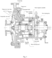
- a currently known magnetic drive pump consists of a pump body, an impeller, a pump cover, an outer magnetic assembly, a drive component, an inner magnetic assembly, double thrust bearings, a containment shell, a pump shaft, two shaft sleeves, a set of sleeve bearing assembly, a motor, etc., where a sleeve bearing is mounted in an inner hole of the pump cover through a sleeve bearing seat.
- the inner and outer magnetic assemblies are isolated by the non-magnetic containment shell, and the containment shell is fastened to the pump cover by a wear gasket.
- the inner magnetic assembly connected to the impeller is driven by the outer magnetic assembly connected to the motor through the action of a magnetic field, so that the pump delivers a medium in a fully-sealed and leak-free manner. Due to the leak-free characteristic, the magnetic pump is widely used in the delivery of flammable, explosive, highly toxic, valuable, and corrosive media in the fields of petrochemicals and the like.
- the bearing Since an inner rotor component of the magnetic pump is immersed in the medium, as a support for the inner rotor component, the bearing is generally a sleeve bearing, which is lubricated by the medium being delivered.
- the sleeve bearing needs to be made of a wear-resistant ceramic material, such as silicon carbide ceramic which is currently widely used in magnetic pumps.
- the silicon carbide ceramic has a very small thermal coefficient of expansion, which is about 4 ⁇ 10 -6 /°C, while metal materials used for bearing seats have higher coefficients of expansion, where commonly used martensitic stainless steel has a thermal coefficient of expansion of 11 ⁇ 10 -6 /°C, and austenitic stainless steel has a thermal coefficient of expansion of 16 ⁇ 10 -6 /°C, about 2.5-4 times that of the silicon carbide bearing. This will cause a huge differential expansion between the silicon carbide sleeve bearing and a metal bearing seat base.
- the interference fit can prevent looseness at high temperatures. Due to the large differential expansion, a large amount of interference is required to avoid looseness of the sleeve bearing and the bearing seat. Taking the matching size of the foregoing sleeve bearing having a diameter of 100 mm as an example, an interference of at least 0.21 mm is required.
- the silicon carbide having an elastic modulus of about 450 GPa and bending and shear strength lower than that of metals is a brittle material. Therefore, after assembly, under normal temperature and cold conditions, the stress at the sleeve bearing is very large, and the stress at a diversion trench has exceeded the compressive strength of the silicon carbide material, so fracture and damage are prone to occur.
- the interference assembly results in a very large stress, which can reach about 1,000 Mpa, even exceeds the tensile strength of commonly used metal materials, and far exceeds the yield stress of commonly used metal materials for magnetic pumps, leading to yielding deformation or even rupture of the bearing seat.
- the stress acting on the bearing seat also leads to large deformation of the bearing seat, with a significant increase in the size of an outer circumferential surface by 0.12 mm.
- the sleeve bearing needs to be repaired to be similar in size to the inner hole of the pump cover before being mounted into a positioning hole of the pump cover.
- the interference between the silicon carbide bearing with a small thermal coefficient of expansion and a small amount of expansion and the bearing seat base decreases, so that the deformation caused by the interference stress on the bearing seat base decreases, the clearance between the silicon carbide bearing and the inner hole of the freely expanding pump cover increases, the sleeve bearing deviates from the pump cover, the rotor deviates from the base, the impeller wear ring on the rotor is scraped, the service life is shortened, the vibration increases, and the sleeve bearing is fractured. Once the sleeve bearing is fractured, the rotor of the magnetic pump will collide with the containment shell, resulting in damage to the containment shell and serious safety accidents such as leakage of high-temperature flammable media.
- the currently known high-temperature magnetic pump employs a small interference fit between the sleeve bearing and the bearing seat and anti-rotation arrangement that a set screw supports the sleeve bearing, and the clearance of the impeller wear ring is significantly increased to prevent collision during operation.
- the wear ring is not collided, the increase in the clearance of the wear ring leads to a significant increase in reflux loss at the wear ring and a significant decrease in the efficiency of the magnetic pump, with higher energy consumption.
- the small interference fit design increases the clearance between the sleeve bearing and the bearing seat at high temperatures to cause their looseness, the sleeve bearing is prone to local cracks and damage over time under the action of high temperature and vibration force, and the bearing seat is prone to leaning to one side due to loose fit with the pump cover, so that the rotor is eccentric to increase the vibration.
- the structural design of the sleeve bearing of the currently known magnetic pump has the problems of looseness at high temperatures and inability to maintain coaxiality at all times.
- the currently known high-temperature magnetic pump has hidden defects that affect its reliable operation, and can rely on only multiple times of shutdown, disassembly, and wear inspection to reduce the probability of accidents.
- the biggest hidden risk of the currently known magnetic pump used under high-temperature conditions is the reliability of the sleeve bearing.
- the currently known magnetic pump can barely be used under high-temperature conditions, its high vibration, many hidden dangers of use, poor reliability, and short maintenance intervals are not conducive to the requirements of the petrochemical industry for long-term safe and reliable operation of devices.
- the currently known magnetic pump has a high fault rate and high safety risk, and its low operating efficiency results in high energy consumption, which is not conducive to a goal of energy conservation and carbon emission reduction.
- the present disclosure aims to provide a high-temperature magnetic drive pump and a design and development method therefor in response to the above problems in the prior art.
- the core of the present disclosure is to reduce the structural stiffness of a surface of a supporting portion of a bearing seat, reduce the stress generated during large interference assembly, avoid damage to the sleeve bearing, reduce assembly and disassembly force, and facilitate maintenance without affecting the fit size between the bearing seat and an outer mounting base, so that the sleeve bearing always maintains coaxiality with the mounting base.
- the present disclosure optimizes only the design and development of the structure of the sleeve bearing of the high-temperature magnetic drive pump, and all other structures are based on the prior art.
- a design and development method for a high-temperature magnetic drive pump includes the following steps:
- the supporting sheet is located at a portion of fit between the bearing seat and the sleeve bearing.
- the spiral gap has an involute or circular arc or approximately circular arc shape.
- a ratio of a radial distance between the tail end of the spiral gap and the surface of the inner hole of the bearing seat to a length of the spiral gap is 0.1 to 0.25.
- the supporting sheet has a wall thickness of at least 0.5 mm, where the starting end of the spiral line intersects with the inner surface of the inner hole of the bearing seat.
- step 500 the number of spiral gaps is not less than six.
- starting and ending lengths of adjacent spiral gaps are located at the same circumferential azimuth angle in the circumferential direction, so as to form a sheet structure on the inner surface of the bearing seat, where one end of the sheet is suspended, and the other end is fixed to the base of the bearing seat to form a cantilever beam-type sheet.
- step S10 the differential expansion is calculated according to a linear coefficient of expansion of the bearing seat, a linear coefficient of expansion of a sleeve bearing material, a size of an outer diameter mating portion of the sleeve bearing, and the design temperature required by the magnetic drive pump.
- step S20 the size of the inner hole of the bearing seat is determined according to the differential expansion, the outer diameter of the sleeve bearing, and an amount of interference, where the amount of interference is an increase in the differential expansion by pre-tightening force, and the amount of interference replaces the differential expansion to achieve an anti-loosening effect at high temperatures.
- the amount of interference is 115% to 130% of the differential expansion.
- a high-temperature magnetic drive pump is designed and developed through the above design and development method for a high-temperature magnetic drive pump.
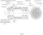
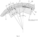
- 1 Bearing seat; 2. Sliding bearing; 3. Spiral gap; 4. Sheet; 5. Spiral line; 31. Starting end (of spiral gap 3); 32. Tail end (of spiral gap 3).
- a design and development method for a high-temperature magnetic drive pump includes the following steps:
- a plurality of spiral gaps 3 of the same shape and length are uniformly arranged in a circumferential direction on a surface of an inner hole of a bearing seat 1 of the magnetic drive pump, and openings of the spiral gaps 3 are arranged on the surface of the inner hole, with tail ends located in a base of the bearing seat 1;
- the spiral gap 3 is involute or replaced by an approximately circular arc
- a ratio X of a radial distance h 1 between the tail end 32 of the spiral gap 3 and the surface of the inner hole of the bearing seat 1 to a length of the spiral gap 3 is 0.1 to 0.25
- a sheet 4 at its starting end has a solid wall thickness h 0 of at least 0.5 mm.
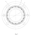
- the number of gaps 3 on one circle is not less than 6 and is between 6 and 16, an angle of each gap 3 in the circumferential direction is greater than (360°/the number of gaps 3), as shown in Fig. 6 and Fig. 7 .
- the length of the spiral gap 3 is limited to ensure that the angle of each gap 3 in the circumferential direction is greater than (360°/the number of gaps 3), that is, starting and ending lengths of adjacent spiral gaps 3 are located at the same circumferential azimuth angle A in the circumferential direction, so that starting from any position on the surface of the inner hole of the bearing seat 1, at least one gap 3 is passed radially outward.
- Starting and ending azimuths pass through two gaps 3, so as to form a sheet 4 structure on the inner surface of the bearing seat 1, where one end of the sheet 4 is suspended and the other end is fixed to the base of the bearing seat 1 to form a cantilever beam-type sheet 4.
- the solid thickness inside the gap 3 and between the gaps 3 is the wall thickness h of the sheet 4, and the length L between the starting end 31 of the gap 3 and the tail end 32 of the adjacent gap 3 is the length between a force point of the cantilever beam and a fixed end.
- the temperature increases by ⁇ t compared to normal temperature.
- a size of an outer diameter mating portion of the sleeve bearing 2 is d
- a linear coefficient of expansion of the metal bearing seat 1 is ⁇ 1
- a linear coefficient of expansion of a silicon carbide sleeve bearing 2 material is ⁇ 2
- a size of the inner hole of the bearing seat 1 is determined according to the differential expansion, an outer diameter of the sleeve bearing 2, and interference requirements at the design temperature;
- an amount of interference increased by 15% to 30% from the differential expansion ⁇ d (because a coefficient of friction of a sleeve bearing 2 pair is very small, an anti-rotating effect can be achieved only by slightly increasing pre-tightening force) is preferably used as a design amount of interference ⁇ d s to serve as an initial inner hole size (d- ⁇ d s ) of the bearing seat 1.
- the pre-tightening force generated by some interference is added as anti-loosening requirements at high temperatures.
- a strength of the supporting sheet 4 of the bearing seat 1 is checked and a structural size and/or shape and/or quantity of the supporting sheet 4 are continuously adjusted until a stress on the supporting sheet 4 is less than or equal to an allowable stress of a bearing seat material, so as to complete the design of the high-temperature magnetic drive pump, where the supporting sheet 4 is located at a portion of fit between the bearing seat 1 and the sleeve bearing 2.
- the stiffness of the sleeve bearing 2 is very high, the supporting sheet 4 on the bearing seat 1 is lifted by the sleeve bearing 2 to bend and deform at room temperature in a cold state due to interference, and the large interference indicates a large deflection caused by bending, so a large stress is produced.
- the stress is significantly reduced in a case of large interference assembly of the sleeve bearing 2 and the bearing seat 1, and the high-temperature magnetic drive pump is easy to assemble and disassemble and can operate normally at room temperature in a cold state; when operating at the design temperature, the temperature rise decreases the interference between the bearing seat 1 and the sleeve bearing 2, but the two are still in close interference fit, thereby ensuring that the two are not loosened at high temperatures, maintaining the coaxiality between the two, and completely solving the problems and defects of the original high-temperature magnetic pump.
- a high-temperature magnetic drive pump is produced by the design and development method for a high-temperature magnetic drive pump based on Embodiment 1.
- the remaining components are the same as those in the prior art.
- integrated sheets 4 on the inner surface of the sleeve bearing seat 1 of the high-temperature magnetic drive pump are formed by an electrical discharge wire cutting method and are evenly distributed along the circumference, and a plurality of end-closed gaps 3 are cut out to form a plurality of thin supporting sheets of the same size.
- the gaps 3 formed by wire cutting become an activity space required for the radial bending deformation of the supporting sheets 4.
- the high-temperature magnetic pump of the present disclosure completely solves the shortcomings of a conventional leak-free magnetic drive pump operating at high temperatures, such as low pump efficiency, poor operational reliability of the sleeve bearing 2, and inconvenient maintenance, meets the requirements of leak-free medium delivery under high temperature and variable temperature conditions, and has the advantages of low operating vibration, high efficiency, high reliability, and convenient assembly and maintenance.
Landscapes
- Engineering & Computer Science (AREA)
- General Engineering & Computer Science (AREA)
- Mechanical Engineering (AREA)
- Physics & Mathematics (AREA)
- Fluid Mechanics (AREA)
- Structures Of Non-Positive Displacement Pumps (AREA)
Applications Claiming Priority (2)
| Application Number | Priority Date | Filing Date | Title |
|---|---|---|---|
| CN202211649199.1A CN116044773B (zh) | 2022-12-21 | 2022-12-21 | 一种高温磁力传动泵及其设计开发方法 |
| PCT/CN2023/125296 WO2024131241A1 (zh) | 2022-12-21 | 2023-10-19 | 一种高温磁力传动泵及其设计开发方法 |
Publications (2)
| Publication Number | Publication Date |
|---|---|
| EP4411142A1 true EP4411142A1 (de) | 2024-08-07 |
| EP4411142A4 EP4411142A4 (de) | 2025-05-07 |
Family
ID=86120971
Family Applications (1)
| Application Number | Title | Priority Date | Filing Date |
|---|---|---|---|
| EP23837124.9A Pending EP4411142A4 (de) | 2022-12-21 | 2023-10-19 | Magnetische hochtemperatur-antriebspumpe und entwurfs- und entwicklungsverfahren dafür |
Country Status (3)
| Country | Link |
|---|---|
| EP (1) | EP4411142A4 (de) |
| CN (1) | CN116044773B (de) |
| WO (1) | WO2024131241A1 (de) |
Families Citing this family (3)
| Publication number | Priority date | Publication date | Assignee | Title |
|---|---|---|---|---|
| CN116044773B (zh) * | 2022-12-21 | 2023-07-18 | 杭州大路实业有限公司 | 一种高温磁力传动泵及其设计开发方法 |
| CN117869361B (zh) * | 2024-03-13 | 2024-11-12 | 沈阳格瑞德泵业有限公司 | 一种具有远程监控防止泄漏的高压除鳞水泵及其监控方法 |
| CN121273825A (zh) * | 2025-12-11 | 2026-01-06 | 大连罗兰泵业有限公司 | 一种用于陶瓷滑动轴承高温工况时的金属径向弹性护套 |
Family Cites Families (14)
| Publication number | Priority date | Publication date | Assignee | Title |
|---|---|---|---|---|
| US5660481A (en) * | 1987-05-29 | 1997-08-26 | Ide; Russell D. | Hydrodynamic bearings having beam mounted bearing pads and sealed bearing assemblies including the same |
| DE69117907T2 (de) * | 1990-12-27 | 1996-07-25 | Ebara Corp | Wellenbuchse aus Keramik |
| JP2005098315A (ja) * | 2003-09-22 | 2005-04-14 | Ntn Corp | 動圧軸受装置 |
| US7728475B2 (en) * | 2007-02-20 | 2010-06-01 | Hamilton Sundstrand Corporation | Thermally operated rotatable component restraint system |
| CN201401359Y (zh) * | 2009-05-13 | 2010-02-10 | 丹东克隆集团有限责任公司 | 磁力泵滑动轴承装置 |
| CN102410242B (zh) * | 2010-09-25 | 2014-08-20 | 太仓顺达磁力泵科技有限公司 | 一种磁力泵滑动轴承及其间隙补偿结构 |
| CN202579282U (zh) * | 2012-04-11 | 2012-12-05 | 丹东克隆先锋泵业有限公司 | 磁力泵主轴滑动轴承 |
| JP6177059B2 (ja) * | 2013-09-05 | 2017-08-09 | 株式会社日立製作所 | 立軸ポンプ用軸受装置及び立軸ポンプ |
| CN204164177U (zh) * | 2014-10-15 | 2015-02-18 | 哈尔滨东安发动机(集团)有限公司 | 一种轴承衬套结构 |
| CN108984968A (zh) * | 2018-08-22 | 2018-12-11 | 中国北方车辆研究所 | 一种轴承配合公差的优化设计方法及装置 |
| CN109268303B (zh) * | 2018-11-12 | 2024-01-05 | 丹东通博泵业有限公司 | 磁力泵滑动轴承组件及磁力泵 |
| CN214330966U (zh) * | 2021-01-13 | 2021-10-01 | 江苏海狮泵业制造有限公司 | 新型磁力泵防松滑动轴承组件 |
| CN113700737B (zh) * | 2021-06-30 | 2024-03-19 | 平高集团有限公司 | 磁悬浮轴承的保护轴承座及保护轴承安装结构 |
| CN116044773B (zh) * | 2022-12-21 | 2023-07-18 | 杭州大路实业有限公司 | 一种高温磁力传动泵及其设计开发方法 |
-
2022
- 2022-12-21 CN CN202211649199.1A patent/CN116044773B/zh active Active
-
2023
- 2023-10-19 EP EP23837124.9A patent/EP4411142A4/de active Pending
- 2023-10-19 WO PCT/CN2023/125296 patent/WO2024131241A1/zh not_active Ceased
Also Published As
| Publication number | Publication date |
|---|---|
| WO2024131241A1 (zh) | 2024-06-27 |
| EP4411142A4 (de) | 2025-05-07 |
| CN116044773B (zh) | 2023-07-18 |
| CN116044773A (zh) | 2023-05-02 |
Similar Documents
| Publication | Publication Date | Title |
|---|---|---|
| EP4411142A1 (de) | Magnetische hochtemperatur-antriebspumpe und entwurfs- und entwicklungsverfahren dafür | |
| RU2524593C2 (ru) | Узел подшипника ротора | |
| RU2737931C2 (ru) | Центробежный насос для перемещения текучей среды | |
| WO2020028186A1 (en) | Polycrystalline diamond radial bearing | |
| JP2014058986A (ja) | 磁気駆動ポンプ | |
| AU2017204641B2 (en) | Magnetic thrust bearing, turbo machine and method | |
| EP2722527B1 (de) | Vakuumpumpe und rotor dafür | |
| US20120128283A1 (en) | Bearing device, bearing unit, and rotary machine | |
| US7300263B2 (en) | Pump | |
| WO2024199154A1 (zh) | 滑动轴承及其因热膨胀径向间隙变化的控制方法 | |
| EP3732345A1 (de) | Pumpengestängeführungen | |
| US8631961B2 (en) | End wall closure apparatus | |
| US6464452B2 (en) | Vacuum pump | |
| US5389411A (en) | Composite structure forming a wear surface | |
| CN217130082U (zh) | 一种陶瓷推力轴承组件及水润滑螺杆压缩机 | |
| CN215718976U (zh) | 一种磁轴承支承的燃气轮机空心转子结构 | |
| JP3573590B2 (ja) | 遠心ポンプ | |
| EP3502498A1 (de) | Lagerzentrierfeder | |
| CN217761286U (zh) | 一种高温稠油井潜油直线电机及其滑动导套 | |
| US20040175067A1 (en) | Bearing life extender for conveyor type rollers | |
| CN212643041U (zh) | 涡旋压缩机 | |
| RU242394U1 (ru) | Детандер-генераторный агрегат для жидких криогенных диэлектрических сред | |
| RU2827928C1 (ru) | Центробежный многоступенчатый горизонтальный двухопорный насос для перекачивания нефти и нефтепродуктов | |
| CN220828365U (zh) | 一种钎焊结构的离心泵叶轮 | |
| RU2411401C1 (ru) | Корпус центробежного компрессора и способ его изготовления |
Legal Events
| Date | Code | Title | Description |
|---|---|---|---|
| STAA | Information on the status of an ep patent application or granted ep patent |
Free format text: STATUS: UNKNOWN |
|
| STAA | Information on the status of an ep patent application or granted ep patent |
Free format text: STATUS: THE INTERNATIONAL PUBLICATION HAS BEEN MADE |
|
| PUAI | Public reference made under article 153(3) epc to a published international application that has entered the european phase |
Free format text: ORIGINAL CODE: 0009012 |
|
| STAA | Information on the status of an ep patent application or granted ep patent |
Free format text: STATUS: REQUEST FOR EXAMINATION WAS MADE |
|
| 17P | Request for examination filed |
Effective date: 20240117 |
|
| AK | Designated contracting states |
Kind code of ref document: A1 Designated state(s): AL AT BE BG CH CY CZ DE DK EE ES FI FR GB GR HR HU IE IS IT LI LT LU LV MC ME MK MT NL NO PL PT RO RS SE SI SK SM TR |
|
| A4 | Supplementary search report drawn up and despatched |
Effective date: 20250404 |
|
| RIC1 | Information provided on ipc code assigned before grant |
Ipc: F16C 33/04 20060101ALI20250331BHEP Ipc: F16C 17/26 20060101ALI20250331BHEP Ipc: F16C 17/02 20060101ALI20250331BHEP Ipc: F04D 29/047 20060101ALI20250331BHEP Ipc: F16C 27/02 20060101ALI20250331BHEP Ipc: F04D 29/046 20060101ALI20250331BHEP Ipc: F04D 1/00 20060101ALI20250331BHEP Ipc: F04D 13/06 20060101AFI20250331BHEP |
|
| DAV | Request for validation of the european patent (deleted) | ||
| DAX | Request for extension of the european patent (deleted) |