EP4411097A1 - Verbindung eines pvc-fensterrahmen mit aluminium-vorsatzschalen oder -rahmen - Google Patents
Verbindung eines pvc-fensterrahmen mit aluminium-vorsatzschalen oder -rahmen Download PDFInfo
- Publication number
- EP4411097A1 EP4411097A1 EP24155273.6A EP24155273A EP4411097A1 EP 4411097 A1 EP4411097 A1 EP 4411097A1 EP 24155273 A EP24155273 A EP 24155273A EP 4411097 A1 EP4411097 A1 EP 4411097A1
- Authority
- EP
- European Patent Office
- Prior art keywords
- spring
- web
- spreading
- distance
- plate
- Prior art date
- Legal status (The legal status is an assumption and is not a legal conclusion. Google has not performed a legal analysis and makes no representation as to the accuracy of the status listed.)
- Granted
Links
Images


Classifications
-
- E—FIXED CONSTRUCTIONS
- E06—DOORS, WINDOWS, SHUTTERS, OR ROLLER BLINDS IN GENERAL; LADDERS
- E06B—FIXED OR MOVABLE CLOSURES FOR OPENINGS IN BUILDINGS, VEHICLES, FENCES OR LIKE ENCLOSURES IN GENERAL, e.g. DOORS, WINDOWS, BLINDS, GATES
- E06B3/00—Window sashes, door leaves, or like elements for closing wall or like openings; Layout of fixed or moving closures, e.g. windows in wall or like openings; Features of rigidly-mounted outer frames relating to the mounting of wing frames
- E06B3/30—Coverings, e.g. protecting against weather, for decorative purposes
- E06B3/301—Coverings, e.g. protecting against weather, for decorative purposes consisting of prefabricated profiled members or glass
- E06B3/306—Covering plastic frames with metal or plastic profiled members
Definitions
- the invention relates to a connection of a PVC window frame with aluminum facings or frames.
- Plastic has become the material used in many markets for frame profiles for the manufacture of windows and doors due to the efficient processing and durability of the products.
- Plastic profiles are generally mitred and welded together in the mitred area to form a frame.
- the manufacture of window and sash frames from plastic profiles is usually carried out on complex production lines in which the individual work steps are carried out one after the other in a timed manner. In order to enable efficient production, none of the individual work steps may take significantly longer than other work steps, as otherwise the entire production line would have to be operated at a correspondingly slower speed.
- facings or frames made of metal profiles, and in particular aluminum profiles is well known for both wooden and plastic windows.
- the covering of plastic profiles with aluminum facings or frames is primarily done for aesthetic reasons, whereby the aluminum facings or frames can be anodized, painted or otherwise coated in different colors.
- Connecting clips are known in which a spreading spring is arranged on one side; this is attached to a plastic or wooden profile, preferably glued. Furthermore, there is a hole in the connecting clip through which a screw with preferably a sharp tip and sharp-edged A thread is inserted to screw the connecting clip to the base body. This means that the connecting clip is rigidly connected to the base body. This requires very precise manufacturing during assembly. If at least 3 connecting clips are involved in assembling an aluminum profile, they must be arranged as precisely as possible in a straight line. In order to compensate for deviations from this, the connection between the connecting clips and the shells must have corresponding tolerances. The same applies to displacements due to thermal expansion, as the shells and the plastic or wooden profiles have different thermal expansion coefficients.
- DE 3912135 A1 shows clip connectors for fixing metal profiles to wooden frames that are fixed at a fixed height.
- the clip connectors are inserted into a groove on both sides.
- the fixing points to the wooden frame on one side and to the metal profile on the other side are arranged on a straight line. If the grooves are straight, the two parts to be connected are aligned along this straight line.
- DE 19949145 C1 discloses a window or door frame with a rotatable connecting element which has a toothing into which a tool with a corresponding toothing engages.
- the connector also has an inclined surface. The connector can be rotated using the tool so that a force-fit connection is created using the inclined surface.
- US10030435B2 discloses a door with a plastic frame in which panels are used instead of a glass pane. An inner panel is connected to a holder on the side facing away from the building and is thus clamped over the overlap.
- WO 2004/087340 A2 shows a connector for doors and windows, which can be inserted into a slot with a central, larger round opening and moved horizontally, whereby the connector is firmly fixed in the two edge areas of the narrow slot.
- the object of the present invention is therefore to provide a generic composite frame for a window or a door with a base frame made of plastic profiles in conjunction with metal profiles for covering the plastic profiles, in which manufacturing tolerances can be compensated for in the combination.
- the invention solves this problem by a composite frame according to independent claim 1 and a connecting clip according to independent claim 11.
- a composite frame according to the invention for a window or a door comprises a base frame made of welded plastic profiles and an outer front frame made of metal profiles connected to one another in the corner area or, alternatively, at least one outer metal front shell.
- the front frames or front shells each have an outer front surface which, in the installed position, runs vertically towards the outside of the building.
- the base frame also has a plastic profile outer surface which, in the installed position, runs vertically towards the outside of the building.
- the outer front frame or the at least one outer metal front shell are connected to the base frame via connecting clips.
- this is done using a connecting clip that engages in the base profile via holes and is connected to locking grooves in the outer front frame or the at least one outer metal front shell.
- This allows a firm connection that can compensate for manufacturing tolerances as well as heat-related movements.
- the outside in particular is subject to large temperature fluctuations, so that tensions can arise due to the different thermal expansion coefficients between mostly PVC and aluminum.
- the connecting clip has a plate that is at least approximately flat; this is usually completely flat, but it can also be grooved or slightly curved.
- a spreading spring is arranged on both sides of the plate, which does not include the plate edges.
- the two spreading springs are spaced apart by a certain distance a.
- An elastic spring is arranged on one side of the plate, whereby the elastic spring is connected to the plate via a web and the elastic spring leads away from the web and approaches the plane of the plate up to a certain distance b. This means that the distance between the elastic spring and the Plate tends to decrease starting from the web. It is unimportant whether the spring runs in the other direction again at the end to make it easier to thread it in.
- the web is arranged at a distance c from the second spreading spring.
- Holes are arranged in the outer surfaces of the plastic profiles at least approximately at a distance c.
- the description of the exemplary embodiment explains how large a deviation from the exact distance a or c can be.
- the metal profiles or outer metallic facings have locking grooves on the side opposite the outer surfaces of the facings. Since the metal profiles are usually extruded profiles, the locking grooves run in the direction of extrusion.
- the connecting clips are connected via the web in connection with the elastic spring and the second spreading spring on the side of the elastic spring by clipping through the holes. Furthermore, the connecting clips are connected to the metal profiles or outer metallic facings via the locking grooves on the side facing away from the elastic spring.
- the distance b is at least somewhat smaller than the wall thickness of the outer surface of the plastic profile. This ensures that after the connecting clip has been inserted, it is elastically clamped to the plastic profile by the elastic deformation.
- the first bore and the elastic spring as well as the web are matched to each other in such a way that the elastic spring with the web can pass through the first bore with play This makes assembly easier.
- the clearance is preferably 1 to 3 mm.
- the second hole and second expansion spring are matched to each other in such a way that the second expansion spring can be guided through the second hole when compressed and, after insertion, the second expansion spring rests under elastic tension in the second hole. This ensures a firm fit.
- the second expansion spring advantageously has a through-hole. After being inserted into the second hole, the second expansion spring can then be fixed in the through-hole using a screw, as the second expansion spring can then no longer be compressed and the connecting clip cannot jump out of the hole under tension.
- the first spreading spring and the locking grooves are coordinated with one another in such a way that the first spreading spring can be inserted into the locking grooves in the compressed state and, after insertion, the first spreading spring rests in the locking groove under elastic tension.
- the first and/or second expansion springs have at least approximately a rotationally symmetrical basic structure with slots parallel to the axis of rotation. Due to the rotationally symmetrical basic structure, the expansion springs can be particularly easily inserted into holes that are also rotationally symmetrical.
- the connecting clip can be inserted in two directions.
- the distance a is at least approximately equal to the distance c.
- the first spreading spring and the web which connects the elastic spring to the flat plate are thus equidistant from the second spreading spring and are preferably arranged on an axis opposite one another on the two sides of the plate.
- plastic profile inner surface of the plastic profiles opposite the plastic profile outer surface can also be connected via the connecting clips according to the invention to an inner facing frame made of metal profiles connected to one another in the corner area or to at least one inner metallic facing shell.
- a connecting clip according to the invention has an at least approximately flat plate, with a spreading spring arranged on both sides of the plate at a distance a.
- An elastic spring is arranged on one side of the plate. The elastic spring is connected to the plate via a web and the elastic spring approaches the plane of the plate up to a distance b, leading away from the web.
- Figure 1 shows a section through a window or door frame with a sash frame plastic profile 5 and a frame plastic profile 6. Seals 4 are located at the contact points between the sash and frame. Glazing (not shown) is inserted into the rebate in the sash frame.
- the frame is connected to the masonry.
- the window or door frame is inserted in such a way that the sash frame can be opened towards the interior of the building.
- Both the cover frame and the sash frame are made of plastic profiles 5, 6 welded together in the mitre area and each have a plastic profile outer surface 14, 15 which, in the installation position, runs vertically towards the outside of the building A.
- the sash frame plastic profile 5 and the window frame plastic profile 6 are clad using facing panels 2, 3.
- facing frames made of metal profiles connected to one another in the corner area can be used.
- the facing panels 2, 3 are extruded aluminum profiles.
- the facing panels 2, 3 are designed in such a way that they have facing outer surfaces 16, 17 directed towards the outside of the building A, which, in the installed position, run vertically towards the outside of the building A.
- the outer metallic facing shells 2, 3 have locking grooves 18 on the side opposite the facing outer surfaces 16, 17.
- the outer facings 2, 3 are connected to the plastic profiles 5, 6 via connecting clips 1.
- the connecting clip 1 according to the invention, which is in the Figures 2 and 3 perspective and in the Figures 4 to 7 shown in various top views, has a flat plate 7.
- a first and a second spreading spring 8, 9 are arranged on both sides of the plate 7.
- the spreading springs 8, 9 are spaced apart by a distance a; this distance a is shown in the Figures 5 and 6
- an elastic spring 10 is arranged at a distance c from the second spreading spring 9, whereby this elastic spring 10 is arranged via a perpendicular to the plate 7 is connected to the plate 7 by a cylindrical web 11.
- the distance a is the distance between the centers of the first and second spreading springs 8, 9.
- the distance c is the distance between the center of the second spreading spring 9 and the center of the cylindrical web 11.
- the elastic spring 10 leads away from the web 11 and approaches the plane of the plate 7 up to a distance b.
- the distance b is in Figure 5
- the distance b is slightly smaller than the wall thickness of the plastic profile outer surface 14, 15.
- the two distances a and c are the same size; however, this is not mandatory.
- the connecting clips 1 are connected to the sash frame plastic profile 5 and the frame plastic profile 6 via the web 11 in conjunction with the elastic spring 10 and the second spreading spring 9 on one side of the plate 7. This is done by clipping through holes 12, 13 in the sash frame plastic profile 5 and the frame plastic profile 6.
- the holes 12, 13 are particularly in Figure 8
- the distance between the two holes 12, 13 corresponds to the distance c between the second spreading spring 9 and the cylindrical web 11.
- the connecting clips 1 are also connected to the outer facing shells 2, 3 via first spreading springs 8 on the side facing away from the elastic spring 10 by engaging in the locking grooves 18.
- the first bore 12 and the elastic spring 10 as well as the web 11 are coordinated with one another in such a way that the elastic spring 10 with the web 11 can be guided through the first bore 12 with play, preferably 1 to 3 mm.
- the second bore 13 and the second spreading spring 9 are matched to each other in such a way that the second spreading spring 9 in the in a compressed state can be guided through the second bore 13 and after insertion the second expansion spring 9 rests under elastic tension in the second bore 13.
- the connecting clip 1 can be rotated in the second bore 13; this rotational movement is limited by the play of the web 11 in the first bore 12.
- the first hole 12 is exactly the same size as the second hole 13. This means that it is irrelevant in which direction the connecting clip 1 is inserted. Consequently, the elastic spring 10 with the cylindrical web 11 could also be inserted into the second hole 13, while the second expansion spring 9 is inserted into the first hole 12.
- the second expansion spring 9 has a through-hole 19. After insertion in the second hole 13, the second expansion spring 9 can be fixed in the through-hole 19 by means of a screw 20; this is shown in Figure 12 shown.
- the first spreading spring 8 and the locking grooves 18 are coordinated with one another in such a way that the first spreading spring 8 can be inserted into the locking grooves 18 of the outer metallic front shells 2, 3 in the compressed state and the first spreading spring 8 rests under elastic tension in the locking groove 18 after insertion.
- the first and second spreading springs 8, 9 have at least approximately a rotationally symmetrical basic structure with slots parallel to the axis of rotation.
- the installation of the connecting clip 1 in the outer surface 14 of the sash frame plastic profile 5 is shown in the Figures 8 to 12
- Two holes 12, 13 are arranged in the outer surface 14 of the plastic profile 5 at a distance c.
- the hole 12 is the same size as the hole 13.
- the elastic spring 10 and then the web 11 is positioned with play in this hole 12. This means that the hole 12 must have a larger diameter than the web 11, which is round in this embodiment.
- the connecting clip 1 is rotatably connected to the sash frame plastic profile 5 via the second spreading spring 9 in connection with the second hole 13 and with play via the web 11 in connection with the elastic spring 10 with the first hole 12. This enables the web 11 to move in the first hole both in the extension direction of the sash frame plastic profile 5 and in the vertical direction.
- Figure 8 shows the outer surface 14 of a sash frame plastic profile 5.
- two holes 12, 13 are arranged at a distance c, ideally on the same horizontal level.
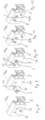
- Figure 9 to Fig 12 show how the connection of the connecting clip 1 with the sash frame plastic profile 5 is made.
- the elastic spring 10 is first inserted into the first hole 12, whereby the main extension direction of the flat plate 7 is approximately perpendicular to the outer surface 14; this is shown in Figure 9
- the connecting clip 1 is moved in such a way that the flat plate 7 is rotated in a position parallel to the outer surface 14 and the second expansion spring 9 is pressed into the second hole 13.
- the web 11 is then located with play in the first hole 12.
- the second expansion spring 9 is centered by its conical head and then compressed so that it can be inserted into the second hole 13 and then expands again so that the second expansion spring 9 sits firmly in the second hole 13.
- the play of the web 11 in the first hole 12 allows the connecting clip 1 to rotate slightly, with the second spreading spring 9 then serving as a pivot point.
- the rotating movement of the connecting clip 1 allows the first spreading spring 8 to move slightly up or down.
- the facing shell 2 can be placed on the plastic profile 5 by putting the locking groove 18 over several first expansion springs 8, which are arranged in a row on the plastic profile 5.
- the first expansion springs 8 are centered by their conical head and then compressed and pressed into the locking groove 18, where the expansion springs expand again and thus create a firm connection.
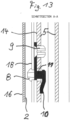
- Figure 13 the elastic spring 10 is shown as if it were not elastically bending. It can be seen that the distance b is smaller than the material thickness of the plastic profile 5. In reality, the elastic spring 10 bends elastically and clamps the connecting clip 1 to the plastic profile 5, so that rattling is avoided.
- the two holes 12, 13 may not be drilled at exactly the same horizontal level during production and/or there is a height offset between individual connecting clips 1, the "floating" bearing of the connecting clips 1 can compensate for this offset without causing tension.
- the invention is not limited to the embodiment.
- the two holes 12, 13 can also have different diameters; in this case, however, the connecting clip 1 can no longer be installed in both directions. It must be ensured that the second spreading spring 9 has approximately the same diameter as the bore into which the second spreading spring 9 is inserted and that the cross-section of the web 11 can be inserted into the other bore with play.
- the distance a between the centers of the first and second spreading springs 8, 9 and the distance c between the center of the second spreading spring 9 and the center of the cylindrical web 11 are the same.
- the first spreading spring 8 and the web 11 are located on a common axis.
- the distance a between the centers of the first and second spreading springs 8, 9 is greater than the distance c between the center of the second spreading spring 9 and the center of the cylindrical web 11, a larger height offset can be compensated.
- the flat plate 7 must then be longer than in the example. If, however, the distance a is smaller than the distance c, a smaller height offset can be compensated.
- a frame usually consists of a lower, upper, left and right side. While the two holes at the top are also arranged horizontally next to each other, the two holes on the two sides are arranged vertically one above the other.
- Plastic window profiles clad with metal profiles or shells always have a cladding on the outside.
- a cladding can also be arranged on the inside using connecting clips according to the invention.
- the connecting clip 1 is rotatably mounted in a plastic profile 5, 6 via the second expansion spring 9 in the second bore 13, while the web 11 of the elastic spring 10 limits this rotational movement.
- the connecting clip 1 is also connected to the facing shells 2, 3 via the first spreading spring 8 and the locking grooves 18.
- the first spreading spring 8 is thus slightly displaced horizontally and vertically by the rotational movement of the connecting clip 1.
- the first spreading spring 8 rotates slightly in the locking groove 18 and is also slightly displaced in it. Since the web 11 of the elastic spring 10 only has a limited range of motion in the first hole 12, the rotational movement is limited, which is why the first spreading spring 8 is only slightly displaced horizontally and vertically. If the range of motion were larger, there would be a risk that the connection between the plastic profiles 5, 6 and the facing shells 2, 3 would become too mobile overall.
- the device according to the invention compensates for usual tolerances, particularly in manually made holes 12, 13.
Landscapes
- Engineering & Computer Science (AREA)
- Civil Engineering (AREA)
- Structural Engineering (AREA)
- Connection Of Plates (AREA)
- Mutual Connection Of Rods And Tubes (AREA)
Abstract
Description
- Die Erfindung betrifft eine Verbindung eines PVC-Fensterrahmens mit Aluminium-Vorsatzschalen oder -rahmen.
- Kunststoff hat sich als Werkstoff für Rahmenprofile zur Herstellung von Fenstern und Türen wegen der rationellen Weiterverarbeitung und Langlebigkeit der Produkte in vielen Märkten durchgesetzt. Kunststoffprofile werden dabei grundsätzlich auf Gehrung geschnitten und im Gehrungsbereich miteinander zu einem Rahmen verschweißt. Zumindest bei größeren Verarbeitern erfolgt die Herstellung von Blend- und Flügelrahmen aus Kunststoffprofilen in der Regel auf komplexen Fertigungsstraßen, bei denen die einzelnen Arbeitsschritte getaktet nacheinander erfolgen. Um eine rationelle Fertigung zu ermöglichen, darf keiner der einzelnen Arbeitsschritte wesentlich länger als andere Arbeitsschritte dauern, da ansonsten die gesamte Fertigungsstraße entsprechend langsamer betrieben werden müsste.
- Die Verwendung von Vorsatzschalen oder -rahmen aus Metallprofilen und insbesondere aus Aluminiumprofilen ist sowohl bei Holz-, als auch bei Kunststofffenstern allgemein bekannt. Die Verkleidung von Kunststoffprofilen mit Aluminiumvorsatzschalen bzw. -rahmen erfolgt in erster Linie aus ästhetischen Gründen, wobei die Aluminiumvorsatzschalen bzw. -rahmen in unterschiedlichen Farben eloxiert, lackiert oder anderweitig beschichtet werden können.
- Es sind Verbindungsclips bekannt, bei welchen auf einer Seite eine Spreizfeder angeordnet ist; diese wird auf einem Kunststoffprofil oder Holzprofil befestigt, vorzugsweise geklebt. Ferner befindet sich in dem Verbindungsclips eine Bohrung, durch welche eine Schraube mit vorzugsweise scharfer Spitze und scharfkantigem Gewinde eingeführt wird, um den Verbindungsclip mit dem Grundkörper zu verschrauben. Hierdurch ist der Verbindungsclip starr mit dem Grundkörper verbunden. Dies bedingt bei der Montage eine sehr genaue Fertigung. Sind bei der Montage eines Aluminiumprofils mindestens 3 Verbindungsclip beteiligt, so müssen diese möglichst exakt in einer Geraden angeordnet sein. Um Abweichungen hiervon auszugleichen, muss die Verbindung zwischen den Verbindungsclips und den Schalen entsprechende Toleranzen aufweisen. Gleiches gilt für Verschiebungen aufgrund von thermischen Ausdehnungen, da die Schalen und die Kunststoff- oder Holzprofile unterschiedliche Wärmeausdehnungskoeffizienten aufweisen.
- Aus
DE 7935702 U1 ist ein Kunststofffenster mit an der Außenseite aufgesetzten Abdeckprofilen aus Leichtmetall bekannt. Hierbei erfolgt die Verbindung über Halteclips, welche über Rastzungen und Verankerungskrallen in die Kunststoffprofile beziehungsweise Abdeckprofile eingreifen. Sowohl die Rastzungen, als auch die Verankerungskrallen haben hierbei jeweils ebene Flächen, welche jeweils parallel eingreifen. Hierdurch ist lediglich ein geradliniges Gleiten möglich. -
DE 3912135 A1 zeigt Clipsverbinder für die Fixierung von Metallprofilen auf Holzrahmen, welche auf einem starren Höhenniveau fixiert sind. Die Clipverbinder werden beidseitig in jeweils eine Nut eingesetzt. Die Fixierungspunkte zum Holzrahmen auf der einen Seite und zu dem Metallprofil auf der anderen Seite sind auf einer geraden Linie angeordnet. Sind die Nuten gerade, so ergibt sich eine Ausrichtung der beiden zu verbindenden Teile entlang dieser Geraden. - Aus
DE 7904496 U1 ist ein Holzrahmen mit Metallrahmen bekannt. Ein Verbinder lässt eine Verdrehung zu, so dass nur zwei Verbinder aufeinander abgestimmt werden können. Liegen hingegen drei Verbinder vor, die nicht auf einer Linie festgeschraubt sind, so kann dies nicht ausgeglichen werden. -
DE 19949145 C1 offenbart einen Fenster- oder Türrahmen mit einem drehbaren Verbindungselement, welches über eine Verzahnung verfügt, in welche ein Werkzeug mit einer korrespondierenden Verzahnung eingreift. Der Verbinder verfügt ferner über eine schräge Fläche. Mittels des Werkzeug lässt sich der Verbinder verdrehen, so dass mittels der schrägen Fläche eine kraftschlüssige Verbindung geschaffen wird. -
US 10030435 B2 -
WO 2004/087340 A2 zeigt einen Verbinder für Türen und Fenster, welcher in ein Langloch mit zentraler, größerer runden Öffnung eingeschoben und horizontal verschoben werden kann, wodurch der Verbinder fest in den beiden Randbereichen des schmalen Langlochs fixiert ist. - Aufgabe der vorliegenden Erfindung ist es daher, einen gattungsgemäßen Verbundrahmen für ein Fenster oder eine Tür mit einem Grundrahmen aus Kunststoffprofilen in Verbindung mit Metallprofilen zur Verkleidung der Kunststoffprofile zu schaffen, bei dem bei der Kombination Fertigungstoleranzen ausgeglichen werden können.
- Die Erfindung löst diese Aufgabe durch einen Verbundrahmen gemäß dem unabhängigen Anspruch 1 sowie einem Verbindungsclip gemäß dem unabhängigen Anspruch 11.
- Ein erfindungsgemäßer Verbundrahmen für ein Fenster oder eine Tür umfasst einen Grundrahmen aus im Gehrungsbereich miteinander verschweißten Kunststoffprofilen sowie einen äußeren Vorsatzrahmen aus im Eckbereich miteinander verbundenen Metallprofilen oder alternativ mindestens eine äußere metallischen Vorsatzschale. In der Regel werden auf der Außenseite alle Kunststoffprofile des Grundrahmens metallisch verkleidet. Die Vorsatzrahmen oder Vorsatzschalen verfügen jeweils über eine Vorsatz-Außenfläche, welche in der Einbauposition vertikal verlaufend zur Gebäudeaußenseite gerichtet ist. Auch der Grundrahmen verfügt über eine Kunststoffprofil-Außenfläche, welche in Einbauposition vertikal verlaufend zur Gebäudeaußenseite gerichtet ist. Der äußeren Vorsatzrahmen oder die mindestens eine äußere metallischen Vorsatzschale sind mit dem Grundrahmen über Verbindungsclips verbunden.
- Erfindungsgemäß geschieht dies über einen Verbindungsclip, der über Bohrungen in das Grundprofil eingreift und anderseits mit Rastnuten in den äußeren Vorsatzrahmen oder der mindestens einen äußere metallischen Vorsatzschale verbunden ist. Dies erlaubt eine feste Verbindung, welche zugleich Fertigungstoleranzen, als auch wärmebedingte Bewegungen ausgleichen kann. Gerade die Außenseite unterliegt großen Temperaturschwankungen, so dass es aufgrund der unterschiedlichen Wärmeausdehnungskoeffizienten zwischen zumeist PVC und Aluminium zu Spannungen kommen kann.
- Der Verbindungsclip verfügt über eine zumindest näherungsweise ebene Platte; zumeist ist diese ganz eben, sie kann jedoch auch geriffelt oder leicht gebogen sein.
- Auf beide Seiten der Platte, worunter nicht die Plattenränder zu verstehen sind, ist jeweils eine Spreizfeder angeordnet. Die beiden Spreizfedern sind mit einem bestimmten Abstand a beabstandet. Auf einer Seite der Platte ist eine elastische Feder angeordnet, wobei die elastische Feder über einen Steg mit der Platte verbunden ist und die elastische Feder vom Steg wegführend sich der Ebene der Platte bis zu einem bestimmten Abstand b annähert. Das bedeutet, dass der Abstand zwischen der elastischen Feder und der Platte von dem Steg beginnend tendenziell abnimmt. Hierbei ist unwesentlich, ob am Ende der Feder diese nochmals in die andere Richtung verläuft, um deren Einfädeln zu erleichtern. Hierbei ist der Steg beabstandet mit einem Abstand c zur zweiten Spreizfeder angeordnet.
- In den Außenflächen der Kunststoffprofile sind zumindest annähernd im Abstand c Bohrungen angeordnet. In der Beschreibung des Ausführungsbeispiel wird darauf eingegangen, wie groß eine Abweichung von dem exakten Abstand a beziehungsweise c sein darf. Die Metallprofilen oder äußeren metallischen Vorsatzschalen verfügen auf der den Vorsatz-Außenflächen gegenüberliegenden Seite über Rastnuten. Da es sich bei den Metallprofilen in der Regel um Strangpressprofile handelt, verlaufen die Rastnuten in Strangpressrichtung. Die Verbindungsclips sind über den Steg in Verbindung mit der elastischen Feder sowie die zweite Spreizfeder auf der Seite der elastischen Feder durch Verclipsung durch die Bohrungen verbunden. Ferner sind die Verbindungsclips mittels der ersten Spreizfedern auf der der elastischen Feder abgewandten Seite über die Rastnuten mit den Metallprofilen oder äußeren metallischen Vorsatzschalen verbunden.
- Vorteilhafte Ausgestaltungen ergeben sich durch die Merkmale der abhängigen Ansprüche.
- Nach einer bevorzugten Ausführungsform der Erfindung ist der Abstand b zumindest etwas kleiner als die Wandstärke der Kunststoffprofil-Außenfläche. Hierdurch wird erreicht, dass nach dem Einsetzen des Verbindungsclips dieser durch die elastische Verformung elastisch klemmend mit dem Kunststoffprofil verbunden ist.
- Vorteilhafterweise sind die erste Bohrung und die elastische Feder sowie der Steg derart aufeinander abgestimmt ist, dass die elastische Feder mit dem Steg mit Spiel durch die erste Bohrung geführt werden kann; dies erleichtert die Montage. Das Spiel beträgt vorzugsweise 1 bis 3 mm.
- Optional sind die zweite Bohrung und zweite Spreizfeder derart aufeinander abgestimmt, dass die zweite Spreizfeder im zusammengedrückten Zustand durch die zweite Bohrung geführt werden kann und nach dem Einsetzen die zweite Spreizfeder unter elastischer Spannung in der zweiten Bohrung anliegt. Hierdurch ist ein fester Sitz gewährleistet.
- Vorteilhafterweise verfügt die zweite Spreizfeder über eine Durchgangsaussparung. Nach dem Einsetzen in der zweiten Bohrung kann dann die zweiten Spreizfeder mittels einer Schraube in der Durchgangsaussparung fixiert wird, da dann die zweite Spreizfeder sich nicht mehr zusammendrücken lässt und der Verbindungsclip nicht unter Spannung aus der Bohrung springen kann.
- Bevorzugt sind die erste Spreizfeder und die Rastnuten derart aufeinander abgestimmt, dass die erste Spreizfeder im zusammengedrückten Zustand in die Rastnuten eingeführt werden kann und nach dem Einsetzen die erste Spreizfeder unter elastischer Spannung in der Rastnut anliegt.
- In einer bevorzugten Ausgestaltung besitzen die erste und / oder zweite Spreizfeder zumindest näherungsweise einen rotationssymetrischen Grundaufbau mit Schlitzen parallel zur Rotationsachse. Durch den rotationssymetrischen Grundaufbau lassen sich die Spreizfedern besonders gut in ebenfalls rotationssymetrische Bohrungen einführen.
- Verfügen die erste und zweite Bohrung über den gleichen Durchmesser, so kann der Verbindungsclip in zwei Richtungen eingesetzt werden.
- Bevorzugt ist der Abstand a zumindest näherungsweise gleich dem Abstand c. Die erste Spreizfeder und der Steg, welcher die elastische Feder mit der ebenen Platte verbindet, sind somit gleichweit von der zweiten Spreizfeder entfernt und bevorzugt auf einer Achse gegenüberliegend auf den beiden Seiten der Platte angeordnet sind.
- Optional kann die der Kunststoffprofil-Außenfläche gegenüberliegende Kunststoffprofil-Innenfläche der Kunststoffprofile ebenfalls über die erfindungsgemäßen Verbindungsclips mit einem innerer Vorsatzrahmen aus im Eckbereich miteinander verbundenen Metallprofilen oder mindestens einer innere metallische Vorsatzschale verbunden sein.
- Ein erfindungsgemäßer Verbindungsclip verfügt über eine zumindest näherungsweise ebene Platte, wobei auf beiden Seiten der Platte beabstandet mit einem Abstand a jeweils eine Spreizfeder angeordnet ist. Auf einer Seite der Platte ist eine elastische Feder angeordnet. Die elastische Feder ist über einen Steg mit der Platte verbunden und die elastische Feder nähert sich vom Steg wegführend der Ebene der Platte bis zu einem Abstand b an.
- Die Erfindung wird nachfolgend anhand von Ausführungsbeispielen sowie der Zeichnung näher erläutert. Es zeigen dabei:
- Fig. 1
- ein Schnitt durch einen erfindungsgemäßen Verbundrahmen;
- Fig. 2
- einen erfindungsgemäßen Verbindungsclip in perspektivischer Ansicht;
- Fig. 3
- denselben erfindungsgemäßen Verbindungsclip in einer anderen dreidimensionalen Ansicht,
- Fig. 4
- denselben erfindungsgemäßen Verbindungsclip in der Draufsicht;
- Fig. 5
- den Verbindungsclip aus
Figur 4 in seitlicher Ansicht; - Fig. 6
- den Verbindungsclip aus
Figur 4 in gegenüberliegender Ansicht; - Fig. 7
- den Verbindungsclip aus
Figur 4 in Stirnseitenansicht; - Fig. 8
- ein Flügelrahmen-Kunststoffprofil vor dem Einsetzen des erfindungsgemäßen Verbindungsclips,
- Fig. 9
- das Flügelrahmen-Kunststoffprofil aus
Figur 8 beim ersten Schritt beim Einsetzen des erfindungsgemäßen Verbindungsclips, - Fig. 10
- das Flügelrahmen-Kunststoffprofil aus
Figur 8 beim zweiten Schritt beim Einsetzen des erfindungsgemäßen Verbindungsclips, - Fig. 11
- das Flügelrahmen-Kunststoffprofil aus
Figur 8 nach dem Einsetzen des erfindungsgemäßen Verbindungsclips. - Fig. 12
- das Flügelrahmen-Kunststoffprofil mit Verbindungsclips aus
Figur 11 nach dem Einsetzen der Schraube und - Fig. 13
- einen Schnitt - wie in
Figur 1 eingezeichnet - zur Verbindung des Flügelrahmen-Kunststoffprofil mit einer Vorsatzschale mittels des erfindungsgemäßen Verbindungsclips. - Gleiche Bezugszeichen in verschiedenen Figuren haben gleiche Bedeutung. Nicht alle Bezugszeichen sind in allen Figuren dargestellt.
-
Figur 1 zeigt einen Schnitt durch einen Fenster- oder Türrahmen mit einem Flügelrahmen-Kunststoffprofil 5 sowie einem Blendrahmen-Kunststoffprofil 6. An den Kontaktstellen zwischen Flügel- und Blendrahmen befinden sich Dichtungen 4. In den Flügelrahmen wird in die Falz eine nicht dargestellte Verglasung eingesetzt. - Der Blendrahmen wird mit dem Mauerwerk verbunden. Der Fenster- oder Türrahmen wird derart eingesetzt, dass der Flügelrahmen zum Gebäudeinneren I geöffnet werden kann.
- Sowohl der Blend-, als auch Flügelrahmen ist aus im Gehrungsbereich miteinander verschweißten Kunststoffprofilen 5, 6 hergestellt und verfügen jeweils über eine Kunststoffprofil-Außenfläche 14, 15, welche in Einbauposition vertikal verlaufend zur Gebäudeaußenseite A gerichtet ist.
- Auf der Gebäudeaußenseite A sind das Flügelrahmen-Kunststoffprofil 5 sowie das Blendrahmen-Kunststoffprofil 6 mittels Vorsatzschalen 2, 3 verkleidet. Alternativ können Vorsatzrahmen aus im Eckbereich miteinander verbundenen Metallprofilen zum Einsatz kommen. Bei den Vorsatzschalen 2, 3 handelt es sich um Aluminium-Strangpressprofile. Die Vorsatzschalen 2, 3 sind derart gestaltet, dass sie über zur Gebäudeaußenseite A gerichteten Vorsatz-Außenfläche 16, 17 verfügen, welche in Einbauposition vertikal verlaufend zur Gebäudeaußenseite A gerichtet sind.
- Die äußeren metallischen Vorsatzschalen 2, 3 verfügen auf der den Vorsatz-Außenflächen 16, 17 gegenüberliegenden Seite über Rastnuten 18.
- Die äußeren Vorsatzschalen 2, 3 sind mit den Kunststoffprofilen 5, 6 über Verbindungsclips 1 verbunden. Der erfindungsgemäße Verbindungsclip 1, der in den
Figuren 2 und 3 perspektivisch und in denFiguren 4 bis 7 in verschiedenen Draufsichten dargestellt ist, verfügt über eine ebene Platte 7. Auf beiden Seiten der Platte 7 ist jeweils eine erste beziehungsweise zweite Spreizfeder 8, 9 angeordnet. Die Spreizfedern 8, 9 sind mit einem Abstand a beabstandet; dieser Abstand a ist in denFiguren 5 und6 eingezeichnet. Auf einer Seite der Platte 7 ist eine elastische Feder 10 im Abstand c von der zweiten Spreizfeder 9 angeordnet, wobei diese elastische Feder 10 über einen senkrecht zur Platte 7 verlaufenden zylindrischen Steg 11 mit der Platte 7 verbunden ist. Bei den Abstand a handelt es sich um die Abstände zwischen den Mitten der ersten und zweiten Spreizfeder 8, 9. Bei den Abstand c handelt es sich um die Abstände zwischen der Mitte der zweiten Spreizfeder 9 und der Mitte des zylindrischen Stegs 11. Die elastische Feder 10 führt vom Steg 11 weg und nähert sich dabei der Ebene der Platte 7 bis zu einem Abstand b an. Der Abstand b ist inFigur 5 eingezeichnet. Der Abstand b ist etwas kleiner als die Wandstärke der Kunststoffprofil-Außenfläche 14, 15. Im Ausführungsbeispiel sind die beiden Abstände a und c gleich groß; dies ist jedoch nicht zwingend. - Die Verbindungsclips 1 werden über den Steg 11 in Verbindung mit der elastischen Feder 10 sowie die zweite Spreizfeder 9 auf der einen Seite der Platte 7 mit dem Flügelrahmen-Kunststoffprofil 5 sowie dem Blendrahmen-Kunststoffprofil 6 verbunden. Dies geschieht durch eine Verclipsung durch Bohrungen 12, 13 in dem Flügelrahmen-Kunststoffprofil 5 sowie dem Blendrahmen-Kunststoffprofil 6. Die Bohrungen 12, 13 sind insbesondere in
Figur 8 dargestellt. Der Abstand zwischen den beiden Bohrungen 12, 13 entspricht dem Abstand c zwischen der zweiten Spreizfeder 9 und dem zylindrischen Stegs 11. - Die Verbindungsclips 1 werden zudem über erste Spreizfedern 8 auf der der elastischen Feder 10 abgewandten Seite mit den äußeren Vorsatzschalen 2, 3 verbunden, indem sie in die Rastnuten 18 eingreifen.
- Die erste Bohrung 12 und die elastischen Feder 10 sowie der Steg 11 sind derart aufeinander abgestimmt, dass die elastischen Feder 10 mit dem Steg 11 mit Spiel, vorzugsweise 1 bis 3 mm, durch die erste Bohrung 12 geführt werden kann.
- Die zweite Bohrung 13 und zweite Spreizfeder 9 sind derart aufeinander abgestimmt, dass die zweite Spreizfeder 9 im zusammengedrückten Zustand durch die zweite Bohrung 13 geführt werden kann und nach dem Einsetzen die zweite Spreizfeder 9 unter elastischer Spannung in der zweiten Bohrung 13 anliegt. Der Verbindungsclip 1 lässt sich in der zweiten Bohrung 13 verdrehen; diese Drehbewegung wird durch das Spiel des Stegs 11 in der ersten Bohrung 12 begrenzt.
- Die erste Bohrung 12 ist beim Ausführungsbeispiel genau so groß wie die zweite Bohrung 13. Dadurch ist ohne Belang, in welche Richtung der Verbindungsclips 1 eingesetzt wird. Demzufolge könnte die elastische Feder 10 mit dem zylindrischen Steg 11 auch in die zweite Bohrung 13 eingesetzt werden, während die zweite Spreizfeder 9 in die erste Bohrung 12 eingesetzt wird.
- Die zweite Spreizfeder 9 verfügt über eine Durchgangsaussparung 19. Nach dem Einsetzen in der zweiten Bohrung 13 kann die zweite Spreizfeder 9 mittels einer Schraube 20 in der Durchgangsaussparung 19 fixiert werden; dies ist in
Figur 12 dargestellt. - Die erste Spreizfeder 8 und die Rastnuten 18 sind derart aufeinander abgestimmt, dass die erste Spreizfeder 8 im zusammengedrückten Zustand in die Rastnuten 18 der äußeren metallischen Vorsatzschalen 2, 3 eingeführt werden kann und die erste Spreizfeder 8 nach dem Einsetzen unter elastischer Spannung in der Rastnut 18 anliegt.
- Die erste und zweite Spreizfeder 8, 9 besitzen zumindest näherungsweise einen rotationssymetrischen Grundaufbau mit Schlitzen parallel zur Rotationsachse.
- Die Montage des Verbindungsclips 1 in der Außenflächen 14 des Flügelrahmen-Kunststoffprofils 5 ist in den
Figuren 8 bis 12 dargestellt. In der Außenflächen 14 des Kunststoffprofils 5 sind im Abstand c zwei Bohrungen 12, 13 angeordnet. Die Bohrung 12 ist gleich groß wie die Bohrung 13. Durch die Bohrung 12 muss die elastische Feder 10 geführt werden und danach wird der Steg 11 mit Spiel in dieser Bohrung 12 positioniert. Dies bedingt, dass die Bohrung 12 einen größeren Durchmesser haben muss als der Steg 11, welcher bei diesem Ausführungsbeispiel rund ausgeführt ist. Der Verbindungsclip 1 ist im montierten Zustand drehbar über die zweite Spreizfeder 9 in Verbindung mit der zweiten Bohrung 13 sowie mit Spiel über den Steg 11 in Verbindung mit der elastischen Feder 10 mit der ersten Bohrung 12 mit dem Flügelrahmen-Kunststoffprofil 5 verbunden. Dies ermöglicht eine Bewegung des Stegs 11 in der ersten Bohrung sowohl in Erstreckungsrichtung des Flügelrahmen-Kunststoffprofils 5, als auch in vertikaler Richtung. -
Figur 8 zeigt die Außenfläche 14 eines Flügelrahmen-Kunststoffprofils 5. In der Außenflächen 14 des Kunststoffprofils 5 sind im Abstand c idealerweise auf demselben horizontalen Niveau zwei Bohrungen 12, 13 angeordnet. -
Figur 9 bis Fig 12 zeigen, wie die Verbindung des Verbindungsclip 1 mit dem Flügelrahmen-Kunststoffprofil 5 erfolgt. Hierzu wird zunächst die elastische Feder 10 in die erste Bohrung 12 eingeführt, wobei die Haupterstreckungsrichtung der ebenen Platte 7 hierbei näherungsweise senkrecht zur Außenfläche 14 ist; dies ist inFigur 9 dargestellt. Dann wird - wie inFigur 10 dargestellt - der Verbindungsclip 1 derart bewegt, dass die ebene Platte 7 in einer Position parallel zur Außenfläche 14 gedreht wird und die zweite Spreizfeder 9 in die zweite Bohrung 13 gedrückt wird. Der Steg 11 befindet sich dann mit Spiel in der ersten Bohrung 12. Die zweite Spreizfeder 9 wird hierbei durch ihren kegelförmigen Kopf zentriert und dann zusammengedrückt, so dass sie in die zweite Bohrung 13 eingeführt werden kann und dehnt sich dann wieder, so dass zweite Spreizfeder 9 fest in der zweite Bohrung 13 sitzt. Die ebenen Platte 7 liegt dann plan auf der Außenfläche 14 auf; dies ist inFigur 11 zu sehen. Wird nun - wie inFigur 12 gezeigt - eine Schraube 20 in die Durchgangsaussparung 19 der zweiten Spreizfeder 9 eingeschraubt, so kann die Spreizfeder 9 nicht mehr gestaucht werden und der Verbindungsclip 1 kann nicht mehr aus der zweiten Bohrung 13 gezogen werden. - Durch das Spiel des Stegs 11 in der ersten Bohrung 12 lässt sich der Verbindungsclip 1 etwas drehen, wobei die zweite Spreizfeder 9 dann als Drehpunkt dient. Durch die Drehbewegung des Verbindungsclips 1 lässt sich die erste Spreizfeder 8 ein wenig nach oben oder unten bewegen.
- Nun kann die Vorsatzschale 2 auf das Kunststoffprofil 5 aufgesetzt werden, indem die Rastnut 18 über mehrere ersten Spreizfedern 8, welche in einer Reihe auf dem Kunststoffprofil 5 angeordnet sind, gestülpt wird. Beim Herunterdrücken der Vorsatzschale 2 werden die ersten Spreizfedern 8 durch ihren kegelförmigen Kopf zentriert und dann gestaucht und so in die Rastnut 18 gedrückt, wo die Spreizfedern sich wieder ausdehnen und somit eine feste Verbindung schaffen. Dies ist in
Figur 13 dargestellt. InFigur 13 die elastische Feder 10 derart dargestellt, als wenn sie sich nicht elastisch verbiegen würde. Es ist zu sehen, dass der Abstand b kleiner wäre als die Materialdicke des Kunststoffprofils 5. In der Realität verbiegt sich die elastische Feder 10 elastisch und klemmt den Verbindungsclip 1 an das Kunststoffprofil 5, so dass Klappern vermieden wird. - Wenn die beiden Bohrungen 12, 13 bei der Fertigung möglicherweise nicht auf exakt gleichem horizontalem Niveau gebohrt werden und / oder zwischen einzelnen Verbindungsclips 1 ein Höhenversatz besteht, kann die "schwimmende" Lagerung der Verbindungsclips 1 diesen Versatz ausgleichen ohne dass es zu Verspannungen kommt.
- Die Erfindung ist nicht auf das Ausführungsbeispiel beschränkt.
- So können die beiden Bohrungen 12, 13 auch unterschiedlichen Durchmesser aufweisen; der Verbindungsclip 1 kann in diesem Fall jedoch nicht mehr in beiden Richtungen eingebaut werden. Vielmehr ist darauf zu achten, dass die zweite Spreizfeder 9 über näherungsweise den gleichen Durchmesser verfügt wie die Bohrung, in welche die zweite Spreizfeder 9 eingeführt wird und der Querschnitt des Stegs 11 mit Spiel in die andere Bohrung eingesetzt werden kann.
- Beim Ausführungsbeispiel sind der Abstand a zwischen den Mitten der ersten und zweiten Spreizfeder 8, 9 sowie der Abstand c zwischen der Mitte der zweiten Spreizfeder 9 und der Mitte des zylindrischen Stegs 11 gleich. Die erste Spreizfeder 8 und der Steg 11 befinden sich auf einer gemeinsamen Achse.
- Ist hingegen der Abstand a zwischen den Mitten der ersten und zweiten Spreizfeder 8, 9 größer als der Abstand c zwischen der Mitte der zweiten Spreizfeder 9 und der Mitte des zylindrischen Stegs 11, so kann ein größerer Höhenversatz ausgeglichen werden. Die ebene Platte 7 muss dann jedoch länger sein als im Ausfürungsbeispiel. Ist hingegen der Abstand a kleiner als der Abstand c, so kann ein kleinerer Höhenversatz ausgeglichen werden.
- Die Figuren zeigen jeweils die unteren Profile eines Rahmens. Ein Rahmen besteht in der Regel aus einer unteren, oberen, linken und rechten Seite. Während oben ebenfalls die beiden Bohrungen horizontal nebeneinander angeordnet sind, sind die beiden Bohrungen an den beiden Seiten vertikal übereinander angeordnet.
- Mit Metallprofilen oder -schalen verkleidete Fenster-Kunststoffprofile verfügen stets über eine Verkleidung auf der Außenseite. Auf der Innenseite können ebenfalls eine Verkleidung über erfindungsgemäße Verbindungsclips angeordnet sein.
- Erfindungswesentlich ist, dass der Verbindungsclip 1 über die zweite Spreizfeder 9 in der zweiten Bohrung 13 drehbar in einem Kunststoffprofil 5, 6 gelagert ist, während der Steg 11 der elastischen Feder 10 diese Drehbewegung begrenzt. Der Verbindungsclip 1 ist darüber hinaus über die erste Spreizfeder 8 und die Rastnuten 18 mit den Vorsatzschalen 2, 3 verbunden. Durch die Drehbewegung des Verbindungsclips 1 wird somit die erste Spreizfeder 8 geringfügig horizontal und vertikal verschoben. Die erste Spreizfeder 8 dreht sich hierbei geringfügig in der Rastnut 18 und wird zugleich ein wenig in ihr verschoben. Da der Steg 11 der elastischen Feder 10 in der ersten Bohrung 12 nur einen begrenzten Bewegungsraum hat, ist die Drehbewegung limitiert, weshalb die erste Spreizfeder 8 nur geringfügig horizontal und vertikal verschoben wird. Wäre der Bewegungsraum größer, so bestünde die Gefahr, dass die Verbindung zwischen den Kunststoffprofilen 5, 6 und den Vorsatzschalen 2, 3 insgesamt zu beweglich würde. Die erfindungsgemäße Vorrichtung kompensiert hingegen übliche Toleranzen insbesondere bei manuell eingebrachten Bohrungen 12, 13.
-
- 1
- Verbindungsclip
- 2
- Vorsatzschale
- 3
- Vorsatzschale
- 4
- Dichtung
- 5
- Kunststoffprofil
- 6
- Kunststoffprofil
- 7
- ebene Platte
- 8
- erste Spreizfeder
- 9
- zweite Spreizfeder
- 10
- elastische Feder
- 11
- Steg
- 12
- Erste Bohrung
- 13
- Zweite Bohrung
- 14
- Kunststoffprofil-Außenfläche
- 15
- Kunststoffprofil-Außenfläche
- 16
- Vorsatz-Außenfläche
- 17
- Vorsatz-Außenfläche
- 18
- Rastnuten
- 19
- Durchgangsaussparung
- 20
- Schraube
21
Claims (11)
- Verbundrahmen für ein Fenster oder eine Tür, umfassend- einen äußeren Vorsatzrahmen aus im Eckbereich miteinander verbundenen Metallprofilen oder mindestens eine äußere metallischen Vorsatzschale (2, 3), welche jeweils über eine Vorsatz-Außenfläche (16, 17) verfügen, welche in Einbauposition vertikal verlaufend zur Gebäudeaußenseite A gerichtet ist,- einen Grundrahmen aus im Gehrungsbereich miteinander verschweißten Kunststoffprofilen (5, 6), welche jeweils über eine Kunststoffprofil-Außenfläche (14, 15) verfügen, welche in Einbauposition vertikal verlaufend zur Gebäudeaußenseite A gerichtet ist,- wobei der äußere Vorsatzrahmen oder die mindestens eine äußere metallischen Vorsatzschale (2, 3) mit dem Grundrahmen über Verbindungsclips (1) verbunden sind,
dadurch gekennzeichnet, dass- die Verbindungsclips (1) über jeweils eine zumindest näherungsweise ebene Platte (7) verfügt,- auf beiden Seite der Platte (7) beabstandet mit einem Abstand a jeweils eine erste beziehungsweise zweite Spreizfeder (8, 9) angeordnet ist,- auf einer Seite der Platte (7) eine elastische Feder (10) angeordnet ist, wobei die elastische Feder (10) über einen Steg (11) mit der Platte (7) verbunden ist, wobei der Steg (11) beabstandet mit einem Abstand c zur zweiten Spreizfeder (9) angeordnet ist, und die elastische Feder (10) vom Steg (11) wegführend sich der Ebene der Platte (7) bis zu einem Abstand b annähert,- in den Außenflächen (14, 15) der Kunststoffprofile (5, 6) zumindest annähernd im Abstand c Bohrungen (12, 13) angeordnet sind,- die Metallprofile oder äußeren metallischen Vorsatzschalen (2, 3) auf der den Vorsatz-Außenflächen (16, 17) gegenüberliegenden Seite über Rastnuten (18) verfügen,- wobei die Verbindungsclips (1) über den Steg (11) in Verbindung mit der elastischen Feder (10) sowie die zweite Spreizfeder (9) auf der Seite der elastischen Feder (10) durch Verclipsung durch die Bohrungen (12, 13) in den Kunststoffprofilen (5, 6) verbunden sind und- die Verbindungsclips (1) mittels der ersten Spreizfedern (8) auf der der elastischen Feder (10) abgewandten Seite über die Rastnuten (18) mit den Metallprofilen oder äußeren metallischen Vorsatzschalen (2, 3) verbunden sind. - Verbundrahmen (2) nach Anspruch 1, dadurch gekennzeichnet, dass der Abstand b zumindest etwas kleiner als die Wandstärke der Kunststoffprofil-Außenfläche (14, 15) ist.
- Verbundrahmen (2) nach Anspruch 1 oder 2, dadurch gekennzeichnet, dass die erste Bohrung (12) und die elastischen Feder (10) sowie der Steg (11) derart aufeinander abgestimmt ist, dass die elastischen Feder (10) mit dem Steg (11) mit Spiel, vorzugsweise 1 bis 3 mm, durch die erste Bohrung (12) geführt werden kann.
- Verbundrahmen (2) nach einem der Ansprüche 1 bis 3, dadurch gekennzeichnet, dass die zweite Bohrung (13) und zweite Spreizfeder (9) derart aufeinander abgestimmt sind, dass die zweite Spreizfeder (9) im zusammengedrückten Zustand durch die zweite Bohrung (13) geführt werden kann und nach dem Einsetzen die zweite Spreizfeder (9) unter elastischer Spannung in der zweiten Bohrung (13) anliegt.
- Verbundrahmen (2) nach Anspruch 4, dadurch gekennzeichnet, dass die zweite Spreizfeder (9) über eine Durchgangsaussparung (19) verfügt und die zweiten Spreizfeder (9) nach dem Einsetzen in der zweiten Bohrung (13) mittels einer Schraube (20) in der Durchgangsaussparung (19) fixiert ist.
- Verbundrahmen (2) nach einem der Ansprüche 1 bis 5, dadurch gekennzeichnet, dass die erste Spreizfeder (8) und die Rastnuten (18) derart aufeinander abgestimmt sind, dass die erste Spreizfeder (8) im zusammengedrückten Zustand in die Rastnuten (18) eingeführt werden kann und nach dem Einsetzen die erste Spreizfeder (8) unter elastischer Spannung in der Rastnut (18) anliegt.
- Verbundrahmen (2) nach einem der Ansprüche 1 bis 6, dadurch gekennzeichnet, dass die erste und / oder zweite Spreizfeder (8, 9) zumindest näherungsweise einen rotationssymetrischen Grundaufbau mit Schlitzen parallel zur Rotationsachse besitzen.
- Verbundrahmen (2) nach einem der Ansprüche 1 bis 7, dadurch gekennzeichnet, dass die erste Bohrung (12) und die zweite Bohrung (13) über den gleichen Durchmesser verfügen.
- Verbundrahmen (2) nach einem der Ansprüche 1 bis 8, dadurch gekennzeichnet, dass der Abstand a zumindest näherungsweise gleich dem Abstand c ist, wobei vorzugsweise die erste Spreizfeder (8) und der Steg (11) auf einer Achse gegenüberliegend auf den beiden Seiten der Platte (7) angeordnet sind.
- Verbundrahmen (2) nach einem der Ansprüche 1 bis 9, dadurch gekennzeichnet, dass ein innerer Vorsatzrahmen aus im Eckbereich miteinander verbundenen Metallprofilen oder mindestens eine innere metallische Vorsatzschale über Verbindungsclips (1) mit der der Kunststoffprofil-Außenfläche (14, 15) gegenüberliegenden Kunststoffprofil-Innenfläche der Kunststoffprofile (5, 6) verbunden ist.
- Verbindungsclip (1) mit einer zumindest näherungsweise ebene Platte (7), wobei auf beiden Seite der Platte (7) beabstandet mit einem Abstand a jeweils eine Spreizfeder (8, 9) angeordnet ist, auf einer Seite der Platte (7) eine elastische Feder (10) angeordnet ist, die elastische Feder (10) über einen Steg (11) mit der Platte (7) verbunden ist und die elastische Feder (10) sich vom Steg (11) wegführend der Ebene der Platte (7) bis zu einem Abstand b annähert, wobei der Steg (11) beabstandet mit einem Abstand c zur zweiten Spreizfeder (9) angeordnet ist.
Applications Claiming Priority (1)
| Application Number | Priority Date | Filing Date | Title |
|---|---|---|---|
| DE102023102772.7A DE102023102772A1 (de) | 2023-02-06 | 2023-02-06 | Verbindung eines PVC-Fensterrahmen mit Aluminium-Vorsatzschalen oder -rahmen |
Publications (3)
| Publication Number | Publication Date |
|---|---|
| EP4411097A1 true EP4411097A1 (de) | 2024-08-07 |
| EP4411097C0 EP4411097C0 (de) | 2025-10-15 |
| EP4411097B1 EP4411097B1 (de) | 2025-10-15 |
Family
ID=89834289
Family Applications (1)
| Application Number | Title | Priority Date | Filing Date |
|---|---|---|---|
| EP24155273.6A Active EP4411097B1 (de) | 2023-02-06 | 2024-02-01 | Verbindung eines pvc-fensterrahmen mit aluminium-vorsatzschalen oder -rahmen |
Country Status (2)
| Country | Link |
|---|---|
| EP (1) | EP4411097B1 (de) |
| DE (1) | DE102023102772A1 (de) |
Families Citing this family (1)
| Publication number | Priority date | Publication date | Assignee | Title |
|---|---|---|---|---|
| DE102023104515A1 (de) | 2023-02-24 | 2024-08-29 | Profine Gmbh | Verbundrahmen für ein Fenster oder eine Tür |
Citations (7)
| Publication number | Priority date | Publication date | Assignee | Title |
|---|---|---|---|---|
| DE7904496U1 (de) | 1979-02-19 | 1979-05-23 | Hipp, Rudi, 7411 Trochtelfingen | Fenster |
| DE7935702U1 (de) | 1979-12-19 | 1980-03-20 | Schueco Heinz Schuermann Gmbh & Co, 4800 Bielefeld | Kunststoffenster mit an der aussenseite aufgesetzten abdeckprofilen aus leichtmetall |
| DE3912135A1 (de) | 1989-04-13 | 1990-10-18 | Lanco Lange Fenster Fassaden | Holz/metall-fenster |
| DE19949145C1 (de) | 1999-10-12 | 2001-02-15 | Unilux Ag | Fenster- oder Türrahmen mit einem Verbindungselement |
| WO2004087340A2 (en) | 2003-03-07 | 2004-10-14 | Palladio Trading S.R.L. | Thermally cut modular metal frame for doors and windows |
| EP2778334B1 (de) * | 2013-03-14 | 2016-08-17 | Johann Gollner | Lüftungsvorrichtung und Scheibenanordnung |
| US10030435B2 (en) | 2015-01-14 | 2018-07-24 | Hatinck, Naamloze Vennootschap | Door leaf with panel and panel kit for such a door leaf |
-
2023
- 2023-02-06 DE DE102023102772.7A patent/DE102023102772A1/de active Pending
-
2024
- 2024-02-01 EP EP24155273.6A patent/EP4411097B1/de active Active
Patent Citations (7)
| Publication number | Priority date | Publication date | Assignee | Title |
|---|---|---|---|---|
| DE7904496U1 (de) | 1979-02-19 | 1979-05-23 | Hipp, Rudi, 7411 Trochtelfingen | Fenster |
| DE7935702U1 (de) | 1979-12-19 | 1980-03-20 | Schueco Heinz Schuermann Gmbh & Co, 4800 Bielefeld | Kunststoffenster mit an der aussenseite aufgesetzten abdeckprofilen aus leichtmetall |
| DE3912135A1 (de) | 1989-04-13 | 1990-10-18 | Lanco Lange Fenster Fassaden | Holz/metall-fenster |
| DE19949145C1 (de) | 1999-10-12 | 2001-02-15 | Unilux Ag | Fenster- oder Türrahmen mit einem Verbindungselement |
| WO2004087340A2 (en) | 2003-03-07 | 2004-10-14 | Palladio Trading S.R.L. | Thermally cut modular metal frame for doors and windows |
| EP2778334B1 (de) * | 2013-03-14 | 2016-08-17 | Johann Gollner | Lüftungsvorrichtung und Scheibenanordnung |
| US10030435B2 (en) | 2015-01-14 | 2018-07-24 | Hatinck, Naamloze Vennootschap | Door leaf with panel and panel kit for such a door leaf |
Also Published As
| Publication number | Publication date |
|---|---|
| DE102023102772A1 (de) | 2024-08-08 |
| EP4411097C0 (de) | 2025-10-15 |
| EP4411097B1 (de) | 2025-10-15 |
Similar Documents
| Publication | Publication Date | Title |
|---|---|---|
| EP2136025B1 (de) | Tor | |
| EP3196396B1 (de) | Bauelement in brandschutzausführung | |
| WO2008135071A1 (de) | Bauelement zum herstellen eines sektionaltorblatts und stirnkappe dafür | |
| EP2792834B1 (de) | Anordnung umfassend ein Halteprofil für ein Rahmenprofil sowie rahmenintegrierte Absturzsicherung | |
| EP4411097B1 (de) | Verbindung eines pvc-fensterrahmen mit aluminium-vorsatzschalen oder -rahmen | |
| DE4119628C1 (en) | Coupler for profiled rail and shower partition - has securing bracket in duct, adjacent laterally to clamping gap | |
| EP2060728B2 (de) | Glashalteleiste, Rahmenkonstruktion sowie Verfahren zur Montage einer Glashalteleiste | |
| EP0906998B1 (de) | Stulpschienenbefestigung | |
| EP3889384A1 (de) | Extrudiertes fenster- oder tür-hohlkammerprofil, system mit einem solchen hohlkammerprofil und daraus hergestellter rahmen | |
| DE3048333C2 (de) | Halterungsvorrichtung für ein Springrollo | |
| DE102006054427B4 (de) | Alu-Kunststoff-Fenster mit Klebebandfixierung | |
| DE102011008765A1 (de) | Profilanordnung, Rahmen und Rahmenanordnung | |
| EP1898041A1 (de) | Vorrichtung und Verfahren zum Befestigen von Aufsatzelementen auf bauseitigen Rahmensystemen | |
| DE202006008297U1 (de) | Profilrahmenkonstruktion mit einem Grundprofil auf einem Pfosten- oder Riegelprofil aus Holz sowie Führungseinrichtung zum Eintreiben von Nägeln | |
| EP1816281B1 (de) | Lamellenanordnung für Gebäudefassaden und dergleichen | |
| DE19601163A1 (de) | Verkleidung für Fenster und Türen | |
| EP4202170B1 (de) | Verbinder, stossverbindung und verfahren zu deren herstellung | |
| EP4575119B1 (de) | T-verbindung und verfahren zur montage einer t-verbindung | |
| DE19734876A1 (de) | Verbindungselement zur Verbindung eines Hohlteils mit einem auf Stoß anliegenden Profilteil im Tür- oder Fensterbau | |
| EP4086417B1 (de) | Schiene für eine schiebetür und montageverfahren | |
| EP3674508B1 (de) | Einbauelement, türanlage mit einbauelement und verfahren zur montage eines einbauelements | |
| EP1980702B1 (de) | Rahmenkonstruktion für Fenster und/oder Türen | |
| DE2248576C3 (de) | Rastbolzen zum Festlegen einer Leiste an einem Fensterrahmen, Türrahmen o.dgl | |
| DE69500536T2 (de) | Verriegelungsvorrichtung für den halbbefestigten Flügel eines Fensters mit zwei Flügeln | |
| EP4696857A1 (de) | Abstandsclip für schwenkbare türen und fenster |
Legal Events
| Date | Code | Title | Description |
|---|---|---|---|
| PUAI | Public reference made under article 153(3) epc to a published international application that has entered the european phase |
Free format text: ORIGINAL CODE: 0009012 |
|
| STAA | Information on the status of an ep patent application or granted ep patent |
Free format text: STATUS: THE APPLICATION HAS BEEN PUBLISHED |
|
| AK | Designated contracting states |
Kind code of ref document: A1 Designated state(s): AL AT BE BG CH CY CZ DE DK EE ES FI FR GB GR HR HU IE IS IT LI LT LU LV MC ME MK MT NL NO PL PT RO RS SE SI SK SM TR |
|
| STAA | Information on the status of an ep patent application or granted ep patent |
Free format text: STATUS: REQUEST FOR EXAMINATION WAS MADE |
|
| 17P | Request for examination filed |
Effective date: 20240814 |
|
| RBV | Designated contracting states (corrected) |
Designated state(s): AL AT BE BG CH CY CZ DE DK EE ES FI FR GB GR HR HU IE IS IT LI LT LU LV MC ME MK MT NL NO PL PT RO RS SE SI SK SM TR |
|
| GRAP | Despatch of communication of intention to grant a patent |
Free format text: ORIGINAL CODE: EPIDOSNIGR1 |
|
| STAA | Information on the status of an ep patent application or granted ep patent |
Free format text: STATUS: GRANT OF PATENT IS INTENDED |
|
| INTG | Intention to grant announced |
Effective date: 20250605 |
|
| GRAS | Grant fee paid |
Free format text: ORIGINAL CODE: EPIDOSNIGR3 |
|
| GRAA | (expected) grant |
Free format text: ORIGINAL CODE: 0009210 |
|
| STAA | Information on the status of an ep patent application or granted ep patent |
Free format text: STATUS: THE PATENT HAS BEEN GRANTED |
|
| AK | Designated contracting states |
Kind code of ref document: B1 Designated state(s): AL AT BE BG CH CY CZ DE DK EE ES FI FR GB GR HR HU IE IS IT LI LT LU LV MC ME MK MT NL NO PL PT RO RS SE SI SK SM TR |
|
| REG | Reference to a national code |
Ref country code: GB Ref legal event code: FG4D Free format text: NOT ENGLISH Ref country code: CH Ref legal event code: F10 Free format text: ST27 STATUS EVENT CODE: U-0-0-F10-F00 (AS PROVIDED BY THE NATIONAL OFFICE) Effective date: 20251015 |
|
| REG | Reference to a national code |
Ref country code: IE Ref legal event code: FG4D Free format text: LANGUAGE OF EP DOCUMENT: GERMAN |
|
| REG | Reference to a national code |
Ref country code: DE Ref legal event code: R096 Ref document number: 502024000292 Country of ref document: DE |
|
| U01 | Request for unitary effect filed |
Effective date: 20251022 |
|
| U07 | Unitary effect registered |
Designated state(s): AT BE BG DE DK EE FI FR IT LT LU LV MT NL PT RO SE SI Effective date: 20251029 |
|
| U20 | Renewal fee for the european patent with unitary effect paid |
Year of fee payment: 3 Effective date: 20260302 |
|
| PG25 | Lapsed in a contracting state [announced via postgrant information from national office to epo] |
Ref country code: ES Free format text: LAPSE BECAUSE OF FAILURE TO SUBMIT A TRANSLATION OF THE DESCRIPTION OR TO PAY THE FEE WITHIN THE PRESCRIBED TIME-LIMIT Effective date: 20251015 |
|
| PG25 | Lapsed in a contracting state [announced via postgrant information from national office to epo] |
Ref country code: NO Free format text: LAPSE BECAUSE OF FAILURE TO SUBMIT A TRANSLATION OF THE DESCRIPTION OR TO PAY THE FEE WITHIN THE PRESCRIBED TIME-LIMIT Effective date: 20260115 |
|
| PG25 | Lapsed in a contracting state [announced via postgrant information from national office to epo] |
Ref country code: HR Free format text: LAPSE BECAUSE OF FAILURE TO SUBMIT A TRANSLATION OF THE DESCRIPTION OR TO PAY THE FEE WITHIN THE PRESCRIBED TIME-LIMIT Effective date: 20251015 |
|
| PG25 | Lapsed in a contracting state [announced via postgrant information from national office to epo] |
Ref country code: RS Free format text: LAPSE BECAUSE OF FAILURE TO SUBMIT A TRANSLATION OF THE DESCRIPTION OR TO PAY THE FEE WITHIN THE PRESCRIBED TIME-LIMIT Effective date: 20260115 |
|
| PG25 | Lapsed in a contracting state [announced via postgrant information from national office to epo] |
Ref country code: IS Free format text: LAPSE BECAUSE OF FAILURE TO SUBMIT A TRANSLATION OF THE DESCRIPTION OR TO PAY THE FEE WITHIN THE PRESCRIBED TIME-LIMIT Effective date: 20260215 |
|
| PG25 | Lapsed in a contracting state [announced via postgrant information from national office to epo] |
Ref country code: PL Free format text: LAPSE BECAUSE OF FAILURE TO SUBMIT A TRANSLATION OF THE DESCRIPTION OR TO PAY THE FEE WITHIN THE PRESCRIBED TIME-LIMIT Effective date: 20251015 |
|
| PG25 | Lapsed in a contracting state [announced via postgrant information from national office to epo] |
Ref country code: SM Free format text: LAPSE BECAUSE OF FAILURE TO SUBMIT A TRANSLATION OF THE DESCRIPTION OR TO PAY THE FEE WITHIN THE PRESCRIBED TIME-LIMIT Effective date: 20251015 |
|
| PG25 | Lapsed in a contracting state [announced via postgrant information from national office to epo] |
Ref country code: CZ Free format text: LAPSE BECAUSE OF FAILURE TO SUBMIT A TRANSLATION OF THE DESCRIPTION OR TO PAY THE FEE WITHIN THE PRESCRIBED TIME-LIMIT Effective date: 20251015 |
|
| PG25 | Lapsed in a contracting state [announced via postgrant information from national office to epo] |
Ref country code: SK Free format text: LAPSE BECAUSE OF FAILURE TO SUBMIT A TRANSLATION OF THE DESCRIPTION OR TO PAY THE FEE WITHIN THE PRESCRIBED TIME-LIMIT Effective date: 20251015 |