EP4410576A1 - Antriebsstrang und fahrzeug - Google Patents
Antriebsstrang und fahrzeug Download PDFInfo
- Publication number
- EP4410576A1 EP4410576A1 EP24152535.1A EP24152535A EP4410576A1 EP 4410576 A1 EP4410576 A1 EP 4410576A1 EP 24152535 A EP24152535 A EP 24152535A EP 4410576 A1 EP4410576 A1 EP 4410576A1
- Authority
- EP
- European Patent Office
- Prior art keywords
- drive train
- electric machine
- output shaft
- drive
- vehicle
- Prior art date
- Legal status (The legal status is an assumption and is not a legal conclusion. Google has not performed a legal analysis and makes no representation as to the accuracy of the status listed.)
- Pending
Links
Images



Classifications
-
- B—PERFORMING OPERATIONS; TRANSPORTING
- B60—VEHICLES IN GENERAL
- B60K—ARRANGEMENT OR MOUNTING OF PROPULSION UNITS OR OF TRANSMISSIONS IN VEHICLES; ARRANGEMENT OR MOUNTING OF PLURAL DIVERSE PRIME-MOVERS IN VEHICLES; AUXILIARY DRIVES FOR VEHICLES; INSTRUMENTATION OR DASHBOARDS FOR VEHICLES; ARRANGEMENTS IN CONNECTION WITH COOLING, AIR INTAKE, GAS EXHAUST OR FUEL SUPPLY OF PROPULSION UNITS IN VEHICLES
- B60K1/00—Arrangement or mounting of electrical propulsion units
- B60K1/04—Arrangement or mounting of electrical propulsion units of the electric storage means for propulsion
-
- B—PERFORMING OPERATIONS; TRANSPORTING
- B60—VEHICLES IN GENERAL
- B60K—ARRANGEMENT OR MOUNTING OF PROPULSION UNITS OR OF TRANSMISSIONS IN VEHICLES; ARRANGEMENT OR MOUNTING OF PLURAL DIVERSE PRIME-MOVERS IN VEHICLES; AUXILIARY DRIVES FOR VEHICLES; INSTRUMENTATION OR DASHBOARDS FOR VEHICLES; ARRANGEMENTS IN CONNECTION WITH COOLING, AIR INTAKE, GAS EXHAUST OR FUEL SUPPLY OF PROPULSION UNITS IN VEHICLES
- B60K17/00—Arrangement or mounting of transmissions in vehicles
- B60K17/04—Arrangement or mounting of transmissions in vehicles characterised by arrangement, location or kind of gearing
- B60K17/12—Arrangement or mounting of transmissions in vehicles characterised by arrangement, location or kind of gearing of electric gearing
-
- B—PERFORMING OPERATIONS; TRANSPORTING
- B60—VEHICLES IN GENERAL
- B60K—ARRANGEMENT OR MOUNTING OF PROPULSION UNITS OR OF TRANSMISSIONS IN VEHICLES; ARRANGEMENT OR MOUNTING OF PLURAL DIVERSE PRIME-MOVERS IN VEHICLES; AUXILIARY DRIVES FOR VEHICLES; INSTRUMENTATION OR DASHBOARDS FOR VEHICLES; ARRANGEMENTS IN CONNECTION WITH COOLING, AIR INTAKE, GAS EXHAUST OR FUEL SUPPLY OF PROPULSION UNITS IN VEHICLES
- B60K17/00—Arrangement or mounting of transmissions in vehicles
- B60K17/28—Arrangement or mounting of transmissions in vehicles characterised by arrangement, location, or type of power take-off
-
- B—PERFORMING OPERATIONS; TRANSPORTING
- B60—VEHICLES IN GENERAL
- B60K—ARRANGEMENT OR MOUNTING OF PROPULSION UNITS OR OF TRANSMISSIONS IN VEHICLES; ARRANGEMENT OR MOUNTING OF PLURAL DIVERSE PRIME-MOVERS IN VEHICLES; AUXILIARY DRIVES FOR VEHICLES; INSTRUMENTATION OR DASHBOARDS FOR VEHICLES; ARRANGEMENTS IN CONNECTION WITH COOLING, AIR INTAKE, GAS EXHAUST OR FUEL SUPPLY OF PROPULSION UNITS IN VEHICLES
- B60K17/00—Arrangement or mounting of transmissions in vehicles
- B60K17/34—Arrangement or mounting of transmissions in vehicles for driving both front and rear wheels, e.g. four wheel drive vehicles
- B60K17/356—Arrangement or mounting of transmissions in vehicles for driving both front and rear wheels, e.g. four wheel drive vehicles having fluid or electric motor, for driving one or more wheels
-
- B—PERFORMING OPERATIONS; TRANSPORTING
- B60—VEHICLES IN GENERAL
- B60K—ARRANGEMENT OR MOUNTING OF PROPULSION UNITS OR OF TRANSMISSIONS IN VEHICLES; ARRANGEMENT OR MOUNTING OF PLURAL DIVERSE PRIME-MOVERS IN VEHICLES; AUXILIARY DRIVES FOR VEHICLES; INSTRUMENTATION OR DASHBOARDS FOR VEHICLES; ARRANGEMENTS IN CONNECTION WITH COOLING, AIR INTAKE, GAS EXHAUST OR FUEL SUPPLY OF PROPULSION UNITS IN VEHICLES
- B60K1/00—Arrangement or mounting of electrical propulsion units
- B60K2001/001—Arrangement or mounting of electrical propulsion units one motor mounted on a propulsion axle for rotating right and left wheels of this axle
-
- F—MECHANICAL ENGINEERING; LIGHTING; HEATING; WEAPONS; BLASTING
- F16—ENGINEERING ELEMENTS AND UNITS; GENERAL MEASURES FOR PRODUCING AND MAINTAINING EFFECTIVE FUNCTIONING OF MACHINES OR INSTALLATIONS; THERMAL INSULATION IN GENERAL
- F16H—GEARING
- F16H37/00—Combinations of mechanical gearings, not provided for in groups F16H1/00 - F16H35/00
- F16H37/02—Combinations of mechanical gearings, not provided for in groups F16H1/00 - F16H35/00 comprising essentially only toothed or friction gearings
- F16H37/06—Combinations of mechanical gearings, not provided for in groups F16H1/00 - F16H35/00 comprising essentially only toothed or friction gearings with a plurality of driving or driven shafts; with arrangements for dividing torque between two or more intermediate shafts
- F16H37/08—Combinations of mechanical gearings, not provided for in groups F16H1/00 - F16H35/00 comprising essentially only toothed or friction gearings with a plurality of driving or driven shafts; with arrangements for dividing torque between two or more intermediate shafts with differential gearing
- F16H37/0833—Combinations of mechanical gearings, not provided for in groups F16H1/00 - F16H35/00 comprising essentially only toothed or friction gearings with a plurality of driving or driven shafts; with arrangements for dividing torque between two or more intermediate shafts with differential gearing with arrangements for dividing torque between two or more intermediate shafts, i.e. with two or more internal power paths
- F16H37/084—Combinations of mechanical gearings, not provided for in groups F16H1/00 - F16H35/00 comprising essentially only toothed or friction gearings with a plurality of driving or driven shafts; with arrangements for dividing torque between two or more intermediate shafts with differential gearing with arrangements for dividing torque between two or more intermediate shafts, i.e. with two or more internal power paths at least one power path being a continuously variable transmission, i.e. CVT
- F16H2037/088—Power-split transmissions with summing differentials, with the input of the CVT connected or connectable to the input shaft
-
- H—ELECTRICITY
- H02—GENERATION; CONVERSION OR DISTRIBUTION OF ELECTRIC POWER
- H02K—DYNAMO-ELECTRIC MACHINES
- H02K16/00—Machines with more than one rotor or stator
-
- H—ELECTRICITY
- H02—GENERATION; CONVERSION OR DISTRIBUTION OF ELECTRIC POWER
- H02K—DYNAMO-ELECTRIC MACHINES
- H02K2213/00—Specific aspects, not otherwise provided for and not covered by codes H02K2201/00 - H02K2211/00
- H02K2213/09—Machines characterised by the presence of elements which are subject to variation, e.g. adjustable bearings, reconfigurable windings, variable pitch ventilators
-
- H—ELECTRICITY
- H02—GENERATION; CONVERSION OR DISTRIBUTION OF ELECTRIC POWER
- H02K—DYNAMO-ELECTRIC MACHINES
- H02K7/00—Arrangements for handling mechanical energy structurally associated with dynamo-electric machines, e.g. structural association with mechanical driving motors or auxiliary dynamo-electric machines
- H02K7/10—Structural association with clutches, brakes, gears, pulleys or mechanical starters
- H02K7/116—Structural association with clutches, brakes, gears, pulleys or mechanical starters with gears
-
- H—ELECTRICITY
- H02—GENERATION; CONVERSION OR DISTRIBUTION OF ELECTRIC POWER
- H02P—CONTROL OR REGULATION OF ELECTRIC MOTORS, ELECTRIC GENERATORS OR DYNAMO-ELECTRIC CONVERTERS; CONTROLLING TRANSFORMERS, REACTORS OR CHOKE COILS
- H02P15/00—Arrangements for controlling dynamo-electric brakes or clutches
-
- H—ELECTRICITY
- H02—GENERATION; CONVERSION OR DISTRIBUTION OF ELECTRIC POWER
- H02P—CONTROL OR REGULATION OF ELECTRIC MOTORS, ELECTRIC GENERATORS OR DYNAMO-ELECTRIC CONVERTERS; CONTROLLING TRANSFORMERS, REACTORS OR CHOKE COILS
- H02P5/00—Arrangements specially adapted for regulating or controlling the speed or torque of two or more electric motors
- H02P5/46—Arrangements specially adapted for regulating or controlling the speed or torque of two or more electric motors for speed regulation of two or more dynamo-electric motors in relation to one another
Definitions
- the invention relates to a drive train according to the preamble of independent claim 1 and a vehicle according to the preamble of independent claim 13.
- EP 3 945 665 A1 discloses a transmission system for an agricultural machine.
- the transmission system disclosed is suitable for operation with an internal combustion engine or a hydraulic motor and comprises a power-split transmission section which has at least one variable transmission branch and a mechanical transmission branch.
- the variable branch has at least one electric machine on the input and output sides for generator and motor operation.
- the electric machines are electrically connected to one another.
- the drive power is divided and directed through the mechanical and variable branches.
- An input-coupled magnetic-electric planetary gear stage brings the variable and mechanical branches together.
- the disadvantage of the transmission system is that it can only be operated with an internal combustion engine.
- the transmission system is structurally complex.
- the present invention is therefore based on the object of proposing a drive train and a vehicle by means of which the aforementioned problems are overcome.
- a drive train and a vehicle are to be proposed which are structurally simpler and/or less complex and/or can only be operated with electric machines and/or can in particular be operated in forward and reverse driving mode.
- a drive train for a vehicle preferably an agricultural vehicle or an agricultural towing vehicle or a construction machine, particularly preferably a tractor
- the drive train comprises a first electric machine and an input shaft, wherein the input shaft is connected to the first electric machine and/or can be driven, in particular is connected in a drivable manner and/or is mechanically coupled or can be mechanically coupled.
- the drive train comprises an energy storage device which is connected to the first electric machine and/or can be coupled, in particular is electrically connected and/or can be electrically coupled.
- the drive train also comprises a Output shaft and a magnetic-electric epicyclic gear stage, which comprises a rotor, in particular an inner rotor, a stator, in particular an outer stator, and in between a modulation ring, in particular a magnetic modulation ring.
- the modulation ring which can in particular comprise or can be an output of the epicyclic gear stage, is connected to the output shaft, in particular drivably connected and/or mechanically coupled or mechanically coupleable.
- the inner rotor is connected to the input shaft, in particular drivably connected and/or mechanically coupled or mechanically coupleable.
- the energy store is connected and/or coupleable to the stator, in particular electrically connected and/or electrically coupleable, so that electrical power can be transferred from the energy store to the stator of the epicyclic gear stage.
- the magnetic-electric planetary gear stage in particular the stator, can be operated, preferably controlled and/or regulated and/or regulated, particularly preferably adjustable and/or adjustable, in such a way that the output shaft can rotate against the direction of rotation of the input shaft, so that the drive train can be operated in forward and reverse driving mode, preferably controlled and/or regulated and/or regulated, particularly preferably adjustable and/or adjustable.
- the direction of rotation of the output shaft can thus be opposite to or opposite to the direction of rotation of the input shaft.
- the magnetic-electric epicyclic gear stage in particular the stator, can be controlled to achieve a direction of rotation of the output shaft that is opposite to the direction of rotation of the input shaft.
- the reverse driving operation of the drive train can be made possible by the speed of the first electric machine in the magnetic-electric epicyclic gear stage being superimposed in such a way that the direction of rotation of the modulation ring or the output of the magnetic-electric epicyclic gear stage, in particular also of the output shaft, can be operated opposite to the direction of rotation of the input shaft or to the forward driving operation, preferably controllable and/or controllable and/or regulated, particularly preferably adjustable and/or adjustable.
- the drive train therefore changes the drive power introduced via the first electric machine and/or the stator or a second electric machine in terms of torque and speed.
- the energy storage device can be a battery and/or a supercapacitor and/or a fuel cell and/or another device for storing electrical energy.
- the first and/or second electric machine can be an electric motor and/or a fuel cell, in particular a direct current and/or three-phase current operated electric motor. Synchronous and/or asynchronous machine with permanent and/or electrical excitation, preferably a permanently excited three-phase synchronous machine.
- the inner rotor can comprise a first number of magnetic pole pairs.
- the inner rotor can be connected to the first electric machine via the input shaft, in particular can be drivably connected and/or mechanically coupled or coupleable.
- the outer stator can be an outer rotor that comprises a second number of magnetic pole pairs.
- the outer stator can be a stator with coils, in particular designed as the second electric machine. If alternating current is applied to the coils, this creates a rotating electromagnetic field.
- the electromagnetic field is equivalent in its function to the outer rotor with permanent magnets.
- the first electric machine and the stator in particular the second electric machine, can be operated in a generator and/or motor mode, preferably controllable and/or controllable and/or regulatable, particularly preferably adjustable and/or adjustable.
- the electrical power of the first electric machine can be greater than the electrical power of the outer stator or the second electric machine.
- the modulation ring may comprise a third number of ferromagnetic segments so that the electromagnetic field between the rotor and the stator is modulated.
- the drive train can comprise a transmission device.
- the transmission device can have a mechanical transmission branch and a variable transmission branch.
- the transmission device, in particular the variable transmission branch can comprise the magnetic-electrical planetary gear stage.
- the variable transmission branch can be connected to the energy storage device and thus in particular also to the first electric machine.
- the variable transmission branch can be connected to the stator, in particular to the second electric machine.
- the drive power can be divided and directed by the mechanical and variable transmission branches.
- the magnetic-electrical planetary gear stage can be input-coupled.
- the magnetic-electrical planetary gear stage can combine the variable transmission branch and mechanical transmission branch.
- the stator in particular the second electric machine, can therefore be operatively connected to the modulation ring of the magnetic-electrical planetary gear stage, which in turn interacts with the rotor.
- the energy storage device and the stator or the second electric machine together with the magnetic-electrical planetary gear stage represent the variable transmission branch, and together with the input shaft the transmission device.
- the mechanical transmission branch can be formed from the input shaft.
- the magnetic-electrical planetary gear stage can be controlled with the stator, in particular the second electric machine, or the stator itself, in particular the second electric machine itself, in such a way that the output shaft of the magnetic-electrical planetary gear stage can be rotated in the opposite direction to the input shaft.
- An additional reverse gear can be omitted and the entire structure of the drive train is structurally simplified, thereby reducing the number of parts required and the corresponding manufacturing and installation processes.
- the drive train can advantageously be operated fully electrically.
- the drive train comprises a control unit.
- the drive train in particular the first electric machine and/or the energy storage device and/or the magnetic-electric planetary gear stage, preferably the stator, particularly preferably the second electric machine, and/or power electronics and/or a first gear unit and/or a second gear unit and/or a power shift reversing unit and/or one or more actuators of the drive train, can be operated with the control unit, preferably controllable and/or controllable and/or regulatable, particularly preferably adjustable and/or adjustable.
- the magnetic-electric planetary gear stage in particular the stator, can be operated with the control unit, preferably controllable and/or controllable and/or regulatable, particularly preferably adjustable and/or adjustable, such that the output shaft can be rotated in the opposite direction to the direction of rotation of the input shaft, so that the drive train can be operated in forward and reverse driving mode.
- control unit preferably controllable and/or controllable and/or regulatable, particularly preferably adjustable and/or adjustable, such that the output shaft can be rotated in the opposite direction to the direction of rotation of the input shaft, so that the drive train can be operated in forward and reverse driving mode.
- the control unit can be assigned to the drive train or the drive train can comprise the control unit.
- the control unit can be designed as an electronic module, an embedded system, a computing unit, a computer, as a module for controlling and/or regulating the device.
- the control unit can comprise a processor, a memory and/or all software, hardware, algorithms, connections, in particular also sensors, which are required for controlling and/or regulating the drive train.
- a method can be designed as a program or algorithm which can be executed on and/or with the control unit.
- the control unit can comprise any device which can analyse data from different sensors, compare data and make the necessary decisions in order to control and/or regulate and/or carry out the operation of the drive train and the necessary tasks for controlling and/or regulating the operation of the drive train.
- the control unit can be connected to the drive train, in particular the first electric machine and/or the energy storage unit and/or the magnetic-electrical planetary gear stage, preferably the stator, particularly preferably the second electric machine, and/or the power electronics and/or the first gear unit and/or the second gear unit and/or the powershift reversing unit and/or one or more actuators of the drive train, preferably signal-connected and/or signal-transmitting and/or data-conducting.
- the control unit can be designed to operate, preferably control and/or regulate and/or actuate, particularly preferably to set and/or adjust, the first electric machine and/or the energy storage unit and/or the magnetic-electrical planetary gear stage and/or the stator or the second electric machine and/or the power electronics.
- a signal-connected and/or signal-transmitting and/or data-conducting connection can be understood to mean, among other things, that an exchange of signals or data takes place between the connected components.
- signals can be received and sent by the control unit and/or processed and/or edited.
- the connection between the control unit and the components of the drive train can be wired, in particular with a cable, and/or wireless, i.e. by radio, for example with Bluetooth or WLAN.
- the communication bus can be, for example, Isobus, CAN bus or similar.
- another control unit can be controlled and/or regulated and/or activated with the control unit.
- the other control unit can be designed like the control unit.
- the control unit can be assigned to the vehicle, in particular arranged on the vehicle.
- the control unit can also be designed in two parts, for example as part of the vehicle and as part of the drive train.
- the control unit can be directly connected to the input and output unit arranged in a cabin of the vehicle, through which data entered by an operator can be transmitted to the control unit or received and output by it.
- the control unit is indirectly connected to the input and output unit through a higher-level control unit.
- the control unit can be integrated into the input and output unit, or vice versa.
- the drive train comprises power electronics to transmit the electrical power between the first electric machine, the energy storage device and the stator of the magnetic-electric planetary gear stage.
- the energy storage device and the first electric machine and the stator or the second electric machine can be connected to one another, for example by means of cables, so that electrical power can be transferred between them. Electrical power can be transferred from the first electric machine to the energy storage device or vice versa. Electrical power can also be transferred from the energy storage device to the stator or vice versa.
- the first electric machine, the energy storage device and the stator, in particular the second electric machine can be controlled, in particular set and/or adjusted, using the power electronics.
- the power electronics can also communicate with the control unit.
- the power electronics can comprise an electronic control unit and/or an inverter and/or a voltage converter.
- the inverter can convert the voltage of the energy storage device into a voltage required by the first electric machine and/or the stator or the second electric machine. This process can be reversed to charge the energy storage device.
- the voltage converter can also convert the energy of the energy storage device into a voltage required for the vehicle's on-board network. The advantages of this are that a second energy storage unit for operating the on-board network may not be required, devices operated via the voltage of the on-board network (e.g. absorption refrigerator on the 12V connection) can be operated for longer and a discharged energy storage unit for supplying the on-board network can be recharged via the energy storage unit for the drive system.
- the output shaft is a hollow shaft and/or the input shaft is a solid shaft and/or the input shaft is arranged in the output shaft and/or the output shaft is coaxial to the input shaft. This advantageously allows an optimal spatial arrangement of the two shafts in the drive train or vehicle to be realized.
- the first electric machine is connected to a power take-off shaft via or by means of the input shaft, in particular is connected in a driveable manner and/or is mechanically coupled or can be mechanically coupled
- the modulation ring, or in particular the output of the epicyclic gear stage is connected to a drive via or by means of the output shaft, in particular is connected in a driveable manner and/or is mechanically coupled or can be mechanically coupled.
- a drive power i.e. a torque and/or a speed
- a drive power or traction power can be transmitted from the modulation ring to a drive so that the drive train or the vehicle can be driven.
- drive power or traction power can be transmitted from the first electric machine to the magnetic-electric epicyclic gear and from the Modulation ring to the drive.
- the drive can, for example, comprise a first vehicle axle and/or a second vehicle axle and/or a first differential and/or a second differential and/or the ground engagement means(s).
- This design of the drive train is advantageously structurally simpler and less complex.
- the drive train and the vehicle can advantageously only be operated with electric machines, so that an environmentally friendly drive train based only on electrical energy can be realized.
- the first electric machine is connected to the drive via or by means of the input shaft, in particular drivably connected and/or mechanically coupled or mechanically coupleable
- the modulation ring is connected to the PTO via or by means of the output shaft, in particular drivably connected and/or mechanically coupled or mechanically coupleable.
- drive power or traction power can be transmitted from the first electric machine to a drive so that the drive train or the vehicle can be driven.
- drive power can be transmitted from the modulation ring to the PTO.
- drive power can be transmitted from the first electric machine to the magnetic-electric planetary gear and from the modulation ring to the PTO.
- this design of the drive train is structurally simpler and less complex.
- the drive train and the vehicle can advantageously only be operated with electric machines, so that an environmentally friendly drive train based only on electrical energy can be realized.
- the drive train comprises a first and/or second transmission unit.
- the first and/or second transmission unit can be upstream or downstream of the magnetic-electric planetary gear stage, in particular the transmission device, in the power flow, preferably downstream.
- the first and/or second transmission unit can have a reverse gear.
- the first transmission unit can be a stepped transmission, in particular a single-stage transmission or a multi-stage transmission or a dual-clutch transmission, or a continuously variable transmission.
- the second transmission unit can be a power take-off transmission, in particular in a two-stage or four-stage design as a spur gear.
- the stepped transmission can comprise clutches, in particular powershift clutches, and pure or several identical or different gear stages.
- the clutches can connect the engaged gear stages to one another.
- the multi-stage transmission can be switchable into a plurality of powershift stages, in particular be fully power shiftable.
- the continuously variable transmission can include one or more hydraulic variators in order to be able to convert higher drive power safely. Part of the drive power is converted into hydraulic power on the input side of the continuously variable transmission using hydrostats. The proportion of hydraulic power can be varied using the variators. On the output side, the hydraulic energy is converted back into mechanical energy. This advantageously allows additional gears or gear steps to be implemented with the drive train and at the same time the installation space of the drive train can be reduced or kept small.
- the drive train comprises a powershift reversing unit for reversing the direction of travel, in particular a powershiftable or a non-powershiftable powershift reversing unit.
- the powershift reversing unit can be arranged upstream or downstream of the magnetic-electric epicyclic gear stage in the power flow.
- the powershift reversing unit can be a gear stage for reversing the direction of rotation.
- the powershift reversing unit can be arranged in the power flow between the first electric machine and the magnetic-electric epicyclic gear stage or after the magnetic-electric epicyclic gear stage, in particular on and/or on the output shaft.
- the powershift reversing unit can be designed as a single component of the drive train. This reduces complexity.
- the powershift reversing unit can be designed for a lower torque, which reduces production costs and part weight.
- the powershift reversing unit has a planetary gear set.
- a clutch device can be arranged upstream of the powershift reversing unit, in particular the planetary gear set. The clutch device can be used to decouple the powershift reversing unit from the drive train.
- a rear axle bevel gear is connected to the output shaft and/or the output shaft is connected to a gearing of a front axle drive, in particular connected in a driveable manner and/or mechanically coupled or mechanically coupleable.
- expensive and maintenance-prone connecting elements such as a cardan shaft, can be saved due to the direct connection of the output shaft to the rear axle bevel gear.
- the output shaft is connected to a gearing of a front axle drive.
- a front axle drive gear can be connected to the output shaft, in particular connected to the output shaft in a rotationally fixed manner or optionally connected and detachable in a rotationally fixed manner.
- the front axle drive gear can also be arranged independently of the output shaft, for example, as part of the front axle drive.
- the front axle drive gear can engage with a gear on the output shaft, in particular a front axle gear.
- the front axle gear can be connected to the output shaft, in particular connected in a rotationally fixed manner or optionally connected in a rotationally fixed manner or detachable.
- the front axle drive can thus advantageously be connected to the rear axle bevel drive by means of the output shaft, in particular connected in a driveable manner and/or mechanically coupled or mechanically coupleable.
- the output shaft advantageously also takes on the function of connecting a first and second vehicle axle, which means that another connecting element can be saved.
- the invention further relates to a vehicle, preferably an agricultural vehicle or an agricultural towing vehicle or a construction machine, particularly preferably a tractor, tug, with a drive train, in particular a drive train according to one of claims 1 to 13.
- vehicle can comprise the first electric machine and/or the stator or the second electric machine as a drive motor.
- the vehicle can be driven with the drive train, in particular by the first electric machine and/or the stator or the second electric machine.
- the drive train can be drivably connected to at least one vehicle axle of the vehicle, in particular the second vehicle axle or the rear axle, and/or can be drivably connected or drivably connectable to another vehicle axle of the vehicle, in particular the first vehicle axle or the front axle.
- the vehicle according to the invention has the advantages of the drive train according to the invention described above.
- the drive train and the vehicle can be operated as follows.
- the first electric machine can generate drive power with the electrical energy or power from the energy storage device and transmit it as mechanical power to the input shaft.
- electrical energy or power can be transmitted from the energy storage device to the stator, in particular the second electric machine.
- the control and/or regulation and/or activation of the supply and exchange of electrical energy, in particular current and voltage, between the energy storage device and the first electric machine and the stator or second electric machine can be carried out with the power electronics and/or the control unit.
- the The power generated and output by the magnetic-electric epicyclic gear stage in particular the outgoing speed and/or outgoing torque, can be controlled and/or regulated and/or driven, in particular set and/or adjusted.
- the power applied to the rotor, as well as the power applied to the stator determines the power that is set at the modulation ring.
- the power output due to the interaction at the magnetic-electric epicyclic gear, in particular between the stator, modulation ring and rotor, in particular the outgoing speed and/or outgoing torque, can be transmitted with the modulation ring to the output shaft and from the output shaft, depending on the embodiment, to the first or transmission unit and/or the PTO and/or the drive.
- the portion of remaining mechanical power at the input shaft can, depending on the embodiment, be transmitted to the first or transmission unit and/or the PTO and/or the drive.
- Figure 1 shows a schematic representation of a first embodiment of a vehicle 10 according to the invention, here a tractor or tow tractor, with a drive train 20 according to the invention.
- the vehicle 10 can be driven with the drive train 20.
- the drive train 20 comprises a first electric machine 50, an input shaft 52 (see also Figures 2 to 8 ), which is connected to the first electric machine 50, in particular drivably connected and/or mechanically coupled or mechanically coupleable, and an output shaft 54 (see also Figures 2 to 8 ), an energy storage device 58, which is connected and/or can be coupled to the first electric machine 50, and a magnetic-electric planetary gear stage 56.
- the vehicle 10, in particular the drive train 20, comprises a first vehicle axle 26 and a second vehicle axle 28.
- the first vehicle axle 26 can be a front axle and the second vehicle axle 28 a rear axle.
- the first vehicle axle 26 can be designed as a steerable axle.
- the vehicle 10, in particular the drive train 20, can also comprise a first differential 30, in particular a front axle differential.
- the first vehicle axle 26 can be connected to the first differential 30, in particular drivably connected and/or mechanically coupleable or mechanically coupled.
- the vehicle 10, in particular the drive train 20, can also comprise a second differential 32, in particular a rear axle differential.
- the second vehicle axle 28 can be connected to the second differential 32, in particular drivably connected and/or mechanically coupleable or mechanically coupled.
- the first and second differentials 30, 32 can be provided optionally.
- the first electric machine 50 can be designed in particular as an electric motor or fuel cell. With the first electric machine 50, a rotary motion and/or force and/or torque can be generated and transmitted to the first and/or second vehicle axle 26, 28.
- the first and/or second vehicle axle 26, 28 convert the rotary motion and/or force and/or the torque of the first electric machine 22 into a rotational movement and/or force and/or a torque of one or more ground engagement means 36 and thus into a thrust of the vehicle 10.
- the vehicle 10 can have one or more ground engagement means 36, shown here in the form of wheels 38, 40, which engage with a surface 12 for transmitting drive forces and/or by means of which the vehicle 10 is supported on the surface 12.
- the vehicle 10 can also have a chassis (not shown), wherein the chassis can be carried in particular by the wheels 38, 40 suspended from the first and/or second vehicle axle 28, 30.
- a first pair of wheels 38 are arranged on the first vehicle axle 26 and a second pair of wheels 40 are arranged on the second vehicle axle 28.
- the diameters of the wheels 38, 40 can differ from one another, in particular the diameter of the first pair of wheels 38 can be smaller than the diameter of the second pair of wheels 40.
- the ground engagement means 36 can also be designed and arranged as crawlers or chains.
- the vehicle 10, and in particular the drive train 20, can comprise a control unit 42.
- the control unit 42 can be directly connected to an input and output unit 44 arranged in a cabin of the vehicle, through which data entered by an operator can be transmitted to the control device 42 or received and output by it.
- the drive train 20 can be operated with the control unit 42.
- the vehicle 10, in particular the drive train 20, can comprise power electronics 70 to distribute the electrical power or energy between the first electric machine 50, the energy storage device 58 and a stator 62 (see Figures 2 to 8 ) of the magnetic-electric planetary gear stage 56.
- the vehicle 10, in particular the drive train 20, comprises a drive 76.
- the drive 76 can comprise the first vehicle axle 26 and/or the second vehicle axle 28 and/or the first differential 30 and/or the second differential 32 and/or the ground engagement means(s) 36.
- the vehicle 10, in particular the drive train 20, can have a front axle drive 110, which can comprise the first vehicle axle 26 and/or the first differential 30 and/or the ground engagement means(s) 36.
- the vehicle 10, or in particular the drive train 20 can have a rear axle drive 102, which may include the second vehicle axle 28 and/or the second differential 32 and/or the ground engaging means 36.
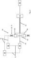
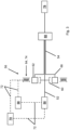
- Figure 2 shows a schematic representation of the first embodiment of the drive train 20 according to the invention.
- the drive train 20 shown essentially corresponds to the one in Figure 1 shown drive train 20, so that only details and/or differences are discussed below.
- the vehicle 10 can have the drive train 20 as shown in Figure 2 shown, include.
- the magnetic-electric planetary gear stage 56 comprises a rotor 60, a stator 64 and a magnetic modulation ring 62 in between.
- the modulation ring 62 is connected to the output shaft 54.
- the rotor 60 is connected to the input shaft 52, in particular drivably connected and/or mechanically coupled or mechanically coupleable.
- the energy storage device 58 is connected and/or coupleable to the first electric machine and the stator 64, in particular a second electric machine 74, in particular electrically connected and/or electrically coupleable, so that electrical power can be transmitted between the components, in particular from and to the energy storage device 58.
- the magnetic-electric planetary gear stage 56, in particular the stator 64 can be operated in such a way that the output shaft 54 can rotate against the direction of rotation of the input shaft 52, so that the drive train 20 can be operated in forward and reverse driving mode.
- the magnetic-electrical planetary gear stage 56 in particular the stator 64, can be controlled to achieve a direction of rotation of the output shaft 54 that is opposite to the direction of rotation of the input shaft 52.
- the magnetic-electrical planetary gear stage 56 in particular the stator 64, can be operated with the control unit 42 in such a way, preferably controlled and/or controlled and/or regulated, particularly preferably adjustable and/or adjustable, that the output shaft 54 can be rotated opposite to the direction of rotation of the input shaft 52, so that the drive train 20 can be operated in a forward and reverse driving mode.
- the reverse driving operation of the drive train 20 can be made possible by superimposing the speed of the first electric machine 50 in the magnetic-electrical planetary gear stage 56 in such a way that the direction of rotation of the modulation ring 62 or the output of the magnetic-electrical planetary gear stage 66, and thus also of the output shaft 54, can be operated in the opposite direction to the direction of rotation of the input shaft 52 or in forward driving operation, preferably controllable and/or adjustable, particularly preferably adjustable and/or adjustable.
- the power electronics 70 can be used to transmit electrical power between the first electric machine 50, the energy storage device 58 and the stator 64 of the magnetic-electric planetary gear stage 56.
- the energy storage device 58 and the first electric machine 50 and the stator 64, in particular the second electric machine 74, can be connected by means of connecting elements, in this case by means of cables 72, so that electrical power can be transmitted between them.
- Electrical power can be transmitted from the first electric machine 50 to the energy storage device 58 and vice versa.
- Electrical power can also be transmitted from the energy storage device 58 to the stator 64 or the second electric machine and vice versa.
- the power electronics 70 can comprise an electronic control unit and/or an inverter and/or a voltage converter.
- the output shaft 54 is designed as a hollow shaft and the input shaft 52 as a solid shaft.
- the input shaft 52 is arranged in the output shaft 54.
- the output shaft 54 is arranged coaxially to the input shaft 52.
- the output shaft 54 can also be designed as a solid shaft and the input shaft 52 as a hollow shaft.
- the input shaft 52 would then be arranged in the output shaft 54.
- the first electric machine 50 is connected to a power take-off shaft 80 via or with the input shaft 52, in particular drivably connected and/or mechanically coupled or mechanically coupleable.
- the modulation ring 60 is connected to the drive 76 via or with the output shaft 54, in particular drivably connected and/or mechanically coupled or mechanically coupleable.
- drive power i.e. torque and/or rotational speed
- drive power or traction power can be transmitted from the modulation ring 60 to the drive 76, so that the drive train 20 or the vehicle 10 can be driven.
- drive power or traction power can be transmitted from the first electric machine 50 to the magnetic-electric planetary gear 56 and from the modulation ring 60 to the drive 76.
- Figure 3 shows a schematic representation of the second embodiment of the drive train 20 according to the invention.
- Figure 3 shown drive train 20 corresponds essentially the Figures 1 and 2 shown drive train 20, so that only details and/or differences are discussed below.
- the vehicle 10 can have the drive train 20 as shown in Figure 3 shown.
- the first electric machine 50 is connected to the drive 76 via the input shaft 52, in particular drivably connected and/or mechanically coupled or mechanically coupleable, and the modulation ring 62 is connected to the power take-off shaft 80 via the output shaft 54, in particular drivably connected and/or mechanically coupled or mechanically coupleable.
- Figures 4 and 5 show schematic representations of a third and fourth embodiment of the drive train 20 according to the invention.
- Figure 4 The drive train 20 shown essentially corresponds to the drive train 20 shown in Figures 1 to 3 shown drive trains 20 and the in Figure 5
- the drive train 20 shown essentially corresponds to the drive train 20 shown in Figures 1 to 4 shown drive trains 20, so that only details and/or differences are discussed below.
- the vehicle 10 can have the drive trains 20 as shown in the Figures 4 and 5 shown, include.
- the drive trains according to the Figures 4 and 5 comprise a first and/or second transmission unit 90, 92.
- the drive train 20 can therefore comprise either the first or the second transmission unit 90, 92 or both or no transmission unit.
- the first and/or second transmission unit 90, 92 can be arranged upstream or downstream of the magnetic-electrical planetary gear stage 56 in the power flow.
- the first and second transmission units 90, 92 are arranged downstream of the magnetic-electrical planetary gear stage 56 in the power flow.
- the first and/or second transmission units 90, 92 can have a reverse gear.
- the first transmission unit 90 can be a stepped transmission, in particular a single-stage transmission or a multi-stage transmission or a dual-clutch transmission, or a continuously variable transmission.
- the second transmission unit 92 can be a power take-off transmission.
- Figure 4 shows a drive train 20, in which the first electric machine 50 is connected to the second transmission unit 92 via the input shaft 52, in particular is connected in a driveable manner and/or is mechanically coupled or can be mechanically coupled.
- the output of the second transmission unit 96 is connected to the power take-off shaft 80, in particular is connected in a driveable manner and/or is mechanically coupled or can be mechanically coupled.
- the modulation ring 62 or the output of the planetary gear stage 66 is connected to the first Gear unit 90 is connected, in particular drivably connected and/or mechanically coupled or mechanically coupleable.
- the output of the first gear unit 94 is connected to the drive 76, in particular drivably connected and/or mechanically coupled or mechanically coupleable.
- Figure 5 shows a drive train 20 with an inverted arrangement.
- the first electric machine 50 is connected to the first gear unit 90 via the input shaft 52, in particular drivably connected and/or mechanically coupled or capable of being coupled.
- the output of the first gear unit 94 is connected to the drive 76, in particular drivably connected and/or mechanically coupled or capable of being coupled mechanically.
- the modulation ring 62 or the output of the epicyclic gear stage 66 is connected to the second gear unit 92 via the output shaft 54, in particular drivably connected and/or mechanically coupled or capable of being coupled mechanically.
- the output of the second gear unit 96 is connected to the power take-off shaft 80, in particular drivably connected and/or mechanically coupled or capable of being coupled mechanically.
- Figures 6 and 7 shows a schematic representation of a fifth and sixth embodiment of the drive train 20 according to the invention.
- Figures 6 and 7 show schematic representations of a fifth and sixth embodiment of the drive train 20 according to the invention.
- Figure 6 The drive train 20 shown essentially corresponds to the drive train 20 shown in Figures 1 to 5 shown drive trains 20 and the in Figure 7
- the drive train 20 shown essentially corresponds to the drive train 20 shown in Figures 1 to 6 shown drive trains 20, so that only details and/or differences are discussed below.
- the vehicle 10 can have the drive trains 20 as shown in the Figures 6 and 7
- the drive train 20 includes a powershift reversing unit 100 for reversing the direction of travel (see Figure 6 ).
- the power shift reversing unit 100 is arranged downstream of the magnetic-electrical planetary gear stage 56 in the power flow.
- the power shift reversing unit 100 can also be arranged upstream of the magnetic-electrical planetary gear stage 56 in the power flow.
- the power shift reversing unit 100 can in particular have a planetary gear set 102 (see Figure 7 ).
- FIG 8 shows a schematic representation of the seventh embodiment of the drive train 20 according to the invention.
- the drive train 20 shown essentially corresponds to the one shown in the Figures 1 and 7 shown drive trains 20, so that in In the following, only details and/or differences are discussed.
- the vehicle 10 may have the drive train 20 as shown in Figure 8 shown.
- a rear axle bevel drive 104 is connected to the output shaft 54, in particular drivably connected and/or mechanically coupled or coupleable.
- the rear axle bevel drive 104 is in turn connected to the rear axle drive 112, in particular drivably connected and/or mechanically coupled or coupleable.
- the output shaft 54 can also be connected to a gearing of a front axle drive 110.
Landscapes
- Engineering & Computer Science (AREA)
- Chemical & Material Sciences (AREA)
- Combustion & Propulsion (AREA)
- Transportation (AREA)
- Mechanical Engineering (AREA)
- Electric Propulsion And Braking For Vehicles (AREA)
Abstract
Description
- Die Erfindung betrifft einen Antriebsstrang gemäss dem Oberbegriff des unabhängigen Anspruchs 1 und ein Fahrzeug gemäss dem Oberbegriff des unabhängigen Anspruchs 13.
-
EP 3 945 665 A1 offenbart ein Getriebesystem für eine landwirtschaftliche Maschine. Das offenbarte Getriebesystem ist geeignet für Betrieb mit einem Verbrennungsmotor oder einem hydraulischen Motor und umfasst einen leistungsverzweigten Getriebeabschnitt, der wenigstens einen variablen Getriebezweig und einen mechanischen Getriebezweig aufweist. Der variable Zweig weist eingangs- und ausgangsseitig jeweils wenigstens eine Elektromaschine für den Generator und Motorbetrieb auf. Die Elektromaschinen sind elektrisch miteinander verbunden. Die Antriebsleistung wird durch den mechanischen und variablen Zweig aufgeteilt und geleitet. Eine eingangsgekoppelte magnetisch-elektrische Umlaufgetriebestufe führt den variablen und mechanischen Zweig zusammen. Nachteil des Getriebesystems ist, dass dieses nur mit einem Verbrennungsmotor betreibbar ist. Darüber hinaus ist das Getriebesystem konstruktiv aufwändig ausgestaltet. - Der vorliegenden Erfindung liegt daher die Aufgabe zugrunde einen Antriebsstrang und ein Fahrzeug vorzuschlagen, durch welche die vorgenannten Probleme überwunden werden. Insbesondere sollen ein Antriebsstrang und ein Fahrzeug vorgeschlagen werden, die konstruktiv einfacher und/oder weniger aufwändig ausgestaltet sind und/oder nur mit Elektromaschinen betreibbar sind und/oder insbesondere in einem Vorwärts- und Rückwärtsfahrbetrieb betreibbar sind.
- Diese Aufgabe wird durch einen Antriebsstrang mit den Merkmalen des Anspruchs 1 und ein Fahrzeug mit den Merkmalen des Anspruchs 13 gelöst. Die abhängigen Ansprüche beziehen sich auf besonders vorteilhafte Ausführungsformen der Erfindung.
- Erfindungsgemäss wird ein Antriebsstrang für ein Fahrzeug, bevorzugt ein landwirtschaftliches Fahrzeug oder ein landwirtschaftliches Zugfahrzeug oder eine Baumaschine, besonders bevorzugt ein Traktor, Schlepper vorgeschlagen. Der Antriebsstrang umfasst eine erste Elektromaschine und eine Eingangswelle, wobei die Eingangswelle mit der ersten Elektromaschine verbunden und/oder antreibbar ist, insbesondere antreibbar verbunden und/oder mechanisch gekoppelt oder mechanisch koppelbar ist. Der Antriebsstrang umfasst einen Energiespeicher, der mit der ersten Elektromaschine verbunden und/oder koppelbar ist, insbesondere elektrisch verbunden und/oder elektrisch koppelbar ist. Der Antriebsstrang umfasst ausserdem eine Ausgangswelle und eine magnetisch-elektrische Umlaufgetriebestufe, die einen Rotor, insbesondere einen inneren Rotor, einen Stator, insbesondere einen äußeren Stator und dazwischen einen Modulationsring, insbesondere einen magnetischen Modulationsring umfasst. Der Modulationsring, der insbesondere einen Abtrieb der Umlaufgetriebestufe umfassen kann oder sein kann, ist mit der Ausgangswelle verbunden, insbesondere antreibbar verbunden und/oder mechanisch gekoppelt oder mechanisch koppelbar. Der innere Rotor ist mit der Eingangswelle verbunden, insbesondere antreibbar verbunden und/oder mechanisch gekoppelt oder mechanisch koppelbar. Der Energiespeicher ist mit dem Stator verbunden und/oder koppelbar, insbesondere elektrisch verbunden und/oder elektrisch koppelbar, sodass elektrische Leistung vom Energiespeicher an den Stator der Umlaufgetriebestufe übertragbar ist. Die magnetisch-elektrische Umlaufgetriebestufe, insbesondere der Stator, ist derart betreibbar, bevorzugt ansteuerbar und/oder steuerbar und/oder regelbar, besonders bevorzugt einstellbar und/oder verstellbar, dass die Ausgangswelle entgegen der Drehrichtung der Eingangswelle rotierbar ist, sodass der Antriebsstrang in einem Vorwärts- und Rückwärtsfahrbetrieb betreibbar ist, bevorzugt ansteuerbar und/oder steuerbar und/oder regelbar, besonders bevorzugt einstellbar und/oder verstellbar. Die Drehrichtung der Ausgangswelle kann somit entgegen der oder entgegengesetzt zur Drehrichtung der Eingangswelle sein.
- Mit anderen Worten, die magnetisch-elektrische Umlaufgetriebestufe, insbesondere der Stator, kann zur Erzielung einer zur Drehrichtung der Eingangswelle entgegengesetzten Drehrichtung der Ausgangswelle ansteuerbar sein. Dabei kann der Rückwärtsfahrbetrieb des Antriebsstrangs dadurch ermöglicht werden, dass die Drehzahl der ersten Elektromaschine in der magnetisch-elektrischen Umlaufgetriebestufe derart überlagerbar ist, dass die Drehrichtung des Modulationsrings bzw. des Abtriebs der magnetisch-elektrischen Umlaufgetriebestufe, insbesondere auch der Ausgangswelle, entgegengesetzt zur Drehrichtung der Eingangswelle bzw. zum Vorwärtsfahrbetrieb betreibbar, bevorzugt ansteuerbar und/oder steuerbar und/oder regelbar, besonders bevorzugt einstellbar und/oder verstellbar ist.
- Der Antriebsstrang verändert also die über die erste Elektromaschine und/oder den Stator bzw. eine zweite Elektromaschine eingeleitete Antriebsleistung in Drehmoment und Drehzahl. Der Energiespeicher kann eine Batterie und/oder eine Superkondensator und/oder eine Brennstoffzelle und/oder eine sonstige Vorrichtung zur Speicherung von elektrischer Energie sein. Die erste und/oder zweite Elektromaschine können ein Elektromotor und/oder eine Brennstoffzelle, insbesondere eine mit Gleichstrom und/oder Drehstrom betriebene Synchron- und/oder Asynchronmaschine mit permanenter und/oder elektrischer Erregung, bevorzugt eine permanenterregte Drehstrom-Synchronmaschine sein.
- Der innere Rotor kann eine erste Anzahl magnetischer Polpaare umfassen. Der innere Rotor kann mit der ersten elektrischen Maschine über die Eingangswelle verbunden sein, insbesondere antreibbar verbunden und/oder mechanisch gekoppelt oder koppelbar sein. Der äussere Stator kann ein äusserer Rotor sein, der eine zweiten Anzahl magnetischer Polpaare umfasst. Ebenso kann der äussere Stator ein Stator mit Spulen, insbesondere als die zweite Elektromaschine ausgebildet sein. Legt man Wechselstrom an die Spulen an, so entsteht dadurch ein rotierendes elektromagnetisches Feld. Das elektromagnetische Feld ist in seiner Funktion dem äußeren Rotor mit Permanentmagneten gleichwertig. Die erste Elektromaschine und der Stator, insbesondere die zweite Elektromaschine, können in einem Generator- und/oder Motorbetrieb betreibbar sein, bevorzugt ansteuerbar und/oder steuerbar und/oder regelbar, besonders bevorzugt einstellbar und/oder verstellbar sein. Die elektrische Leistung der ersten Elektromaschine kann grösser als die elektrische Leistung des äusseren Stators bzw. der zweiten Elektromaschine sein. Der Modulationsring kann eine dritte Anzahl ferromagnetischer Segmente umfassen, sodass das elektromagnetische Feld zwischen Rotor und Stator moduliert.
- Im Speziellen kann der Antriebsstrang eine Getriebeeinrichtung umfassen. Die Getriebeeinrichtung kann einen mechanischen Getriebezweig und einen variablen Getriebezweig aufweisen. Ausserdem kann die Getriebeeinrichtung, insbesondere der variable Getriebezweig, die magnetisch-elektrischen Umlaufgetriebestufe umfassen. Eingangsseitig kann der variable Getriebezweig mit dem Energiespeicher und somit insbesondere auch der ersten Elektromaschine verbunden sein. Ausgangsseitig kann der variable Getriebezweig mit dem Stator, insbesondere der zweiten Elektromaschine verbunden sein. Die Antriebsleistung kann durch den mechanischen und variablen Getriebezweig aufgeteilt und geleitet werden. Die die magnetisch-elektrischen Umlaufgetriebestufe kann eingangsgekoppelt sein. Ausserdem kann die magnetisch-elektrischen Umlaufgetriebestufe den variablen Getriebezweig und mechanischen Getriebezweig zusammenführen. Der Stator, insbesondere die zweite Elektromaschine kann also in Wirkverbindung mit dem Modulationsring der magnetisch elektrischen Umlaufgetriebestufe sein, welcher wiederrum mit dem Rotor zusammenwirkt. Der Energiespeicher und der Stator bzw. die zweite Elektromaschine stellen zusammen mit der magnetisch-elektrischen Umlaufgetriebestufe den variablen Getriebezweig dar, und zusammen mit der Eingangswelle die Getriebeeinrichtung. Der mechanische Getriebezweig kann aus der Eingangswelle gebildet sein. Die magnetisch-elektrische Umlaufgetriebestufe kann mit dem Stator, insbesondere die zweite Elektromaschine, bzw. der Stator selbst, insbesondere die zweite Elektromaschine selbst, derart ansteuerbar sein, dass die Ausgangswelle der magnetisch-elektrischen Umlaufgetriebestufe in Gegenrichtung zur Eingangswelle rotierbar sein kann. Ein zusätzlicher Rückwärtsgang kann entfallen und der gesamte Aufbau des Antriebsstrangs wird konstruktiv vereinfacht, wodurch die benötigte Teileanzahl und entsprechende Herstellungs- und Einbauvorgänge reduziert werden. Darüber hinaus kann der Antriebsstrang vorteilhafterweise voll elektrisch betrieben werden.
- In Ausgestaltung der Erfindung umfasst der Antriebsstrang eine Steuereinheit. Der Antriebsstrang, insbesondere die erste Elektromaschine und/oder der Energiespeicher und/oder die magnetisch-elektrische Umlaufgetriebestufe, bevorzugt der Stator, besonders bevorzugt die zweite Elektromaschine, und/oder eine Leistungselektronik und/oder eine erste Getriebeeinheit und/oder eine zweite Getriebeeinheit und/oder eine Lastschaltwendeeinheit und/oder einer oder mehrere Aktoren des Antriebsstrangs, können mit der Steuereinheit betreibbar, bevorzugt ansteuerbar und/oder steuerbar und/oder regelbar, besonders bevorzugt einstellbar und/oder verstellbar sein. Im Speziellen kann die magnetisch-elektrische Umlaufgetriebestufe, insbesondere der Stator, mit der Steuereinheit derart betreibbar, bevorzugt ansteuerbar und/oder steuerbar und/oder regelbar, besonders bevorzugt einstellbar und/oder verstellbar sein, dass die Ausgangswelle entgegen der Drehrichtung der Eingangswelle rotierbar ist, sodass der Antriebsstrang in einem Vorwärts- und Rückwärtsfahrbetrieb betreibbar ist.
- Die Steuereinheit kann dem Antriebsstrang zugeordnet sein oder der Antriebsstrang kann die Steuereinheit umfassen. Die Steuereinheit kann als ein elektronisches Modul, ein eingebettetes System, eine Recheneinheit, ein Computer, als ein Modul zum Steuern und/oder Regeln der Vorrichtung ausgebildet sein. Die Steuereinheit kann einen Prozessor, einen Speicher und/oder alle Software, Hardware, Algorithmen, Anschlüsse, insbesondere auch Sensoren, umfassen, die für die Steuerung und/oder Regelung des Antriebsstrangs erforderlich sind. Ein Verfahren kann als Programm oder Algorithmus ausgebildet sein, welches auf und/oder mit der Steuereinheit ausführbar ist. Die Steuereinheit kann jedes Gerät umfassen, das Daten von verschiedenen Sensoren analysieren, Daten vergleichen und die erforderlichen Entscheidungen treffen kann, um den Betrieb des Antriebsstrangs und die erforderlichen Aufgaben zur Steuerung und/oder Regelung des Betriebs des Antriebsstrangs zu steuern und/oder zu regeln und/oder auszuführen.
- Die Steuereinheit kann mit dem Antriebsstrang, insbesondere der ersten Elektromaschine und/oder dem Energiespeicher und/oder der magnetisch-elektrischen Umlaufgetriebestufe, bevorzugt dem Stator, besonders bevorzugt der zweiten Elektromaschine, und/oder der Leistungselektronik und/oder der ersten Getriebeeinheit und/oder der zweiten Getriebeeinheit und/oder der Lastschaltwendeeinheit und/oder einem oder mehreren Aktoren des Antriebsstrangs verbunden sein, bevorzugt signalverbunden und/oder signalübertragend und/oder datenleitend verbunden sein. Die Steuereinheit kann zum Betrieb, bevorzugt der Steuerung und/oder Regelung und/oder Ansteuerung, besonders bevorzugt zum Einstellen und/oder Verstellen, der ersten Elektromaschine und/oder des Energiespeichers und/oder der magnetisch-elektrischen Umlaufgetriebestufe und/oder des Stators bzw. der zweiten Elektromaschine und/oder der Leistungselektronik ausgebildet sein. Unter einer signalverbundenen und/oder signalübertragenden und/oder datenleitenden Verbindung kann dabei unter anderem verstanden werden, dass ein Austausch von Signalen bzw. Daten zwischen den verbundenen Bauteilen stattfindet. Signale können beispielsweise von der Steuereinheit empfangen und versendet werden und/oder verarbeitet und/oder bearbeitet werden. Die Verbindung zwischen der Steuereinheit und den Bauteilen des Antriebsstrangs kann kabelgebunden, insbesondere also mit Kabel, und/oder kabellos, also per Funk, beispielsweise mit Bluetooth oder WLAN realisiert sein. Der Kommunikationsbus kann beispielsweise Isobus, CAN-Bus oder ähnliches sein kann. Ausserdem kann mit der Steuereinheit eine weitere Steuereinheit steuerbar und/oder regelbar und/oder ansteuerbar sein. Die weitere Steuereinheit kann wie die Steuereinheit ausgebildet sein. Die Steuereinheit kann dem Fahrzeug zugeordnet, insbesondere am Fahrzeug angeordnet sein. Die Steuereinheit kann auch zweiteilig beispielsweise als Teil des Fahrzeugs und als Teil des Antriebsstrangs ausgebildet sein. Die Steuereinheit kann unmittelbar mit der in einer Kabine des Fahrzeugs angeordneten Ein- und Ausgabeeinheit Verbindung stehen, durch welche von einer Bedienperson eingegebene Daten an die Steuereinheit übertragen oder von dieser empfangen und ausgegeben werden können. Denkbar ist aber auch, dass die Steuereinheit mittelbar durch eine übergeordnete Steuereinheit mit der Ein- und Ausgabeeinheit verbunden ist. Die Steuereinheit kann in die Ein- und Ausgabeeinheit integriert sein, oder umgekehrt.
- In Ausgestaltung der Erfindung umfasst der Antriebsstrang eine Leistungselektronik, um die elektrische Leistung zwischen der ersten Elektromaschine, dem Energiespeicher und dem und dem Stator der magnetisch-elektrischen Umlaufgetriebestufe zu übertragen. Der Energiespeicher und die erste Elektromaschine und der Stator oder die zweite Elektromaschine können miteinander verbunden sein, beispielsweise mittels Kabel, sodass elektrische Leistung zwischen diesen übertragbar ist. Elektrische Leistung kann mit ersten Elektromaschine an den Energiespeicher oder umgekehrt übertragbar sein. Ebenso kann elektrische Leistung vom Energiespeicher an den Stator oder umgekehrt übertragbar sein. Mit der Leistungselektronik können die erste Elektromaschine, der Energiespeicher und der Stator, insbesondere die zweite Elektromaschine, ansteuerbar, insbesondere einstellbar und/oder verstellbar sein. Ebenso kann die Leistungselektronik mit der Steuereinheit kommunizieren. Die Leistungselektronik kann ein elektronisches Steuergerät und/oder einen Inverter und/oder einen Spannungswandler umfassen. Im Betrieb kann der Inverter die Spannung des Energiespeichers in eine Spannung umwandeln, welche die erste Elektromaschine und/oder der Stator bzw. die zweite Elektromaschine benötigen. Zum Aufladen des Energiespeichers kann dieser Vorgang umgekehrt werden. Der Spannungswandler kann aber auch die Energie des Energiespeichers in eine für das Bordnetz des Fahrzeugs benötigte Spannung umwandeln. Als Vorteile daraus ergeben sich, dass ein zweiter Energiespeicher zum Betrieb des Bordnetzes ggf. entfallen kann, über die Spannung des Bordnetzes betriebene Geräte (z.B. Absorptionskühlschrank am 12V Anschluss) länger betrieben werden können und ein entladener Energiespeicher für die Versorgung des Bordnetzes über den Energiespeicher für den Fahrantriebe wieder aufgeladen werden kann.
- In Ausgestaltung der Erfindung ist die Ausgangswelle eine Hohlwelle und/oder die Eingangswelle eine Vollwelle und/oder die Eingangswelle ist in der Ausgangswelle angeordnet und/oder die Ausgangswelle ist koaxial zur Eingangswelle. Dadurch kann vorteilhafterweise eine optimal räumliche Anordnung der beiden Wellen im Antriebsstrang bzw. Fahrzeug realisiert werden.
- In Ausgestaltung der Erfindung ist die erste Elektromaschine über die oder mittels der Eingangswelle mit einer Zapfwelle verbunden, insbesondere antreibbar verbunden und/oder mechanisch gekoppelt oder mechanisch koppelbar, und der Modulationsring, oder insbesondere der der Abtrieb der Umlaufgetriebestufe, ist über die oder mittels der Ausgangswelle mit einem Antrieb verbunden, insbesondere antreibbar verbunden und/oder mechanisch gekoppelt oder mechanisch koppelbar. Dadurch kann eine Antriebsleistung, also ein Drehmoment und/oder eine Drehzahl, von der ersten Elektromaschine auf die Zapfwelle übertragen werden. Ausserdem kann eine Antriebsleistung bzw. Traktionsleistung vom Modulationsring an einen Antrieb übertragen werden, sodass der Antriebsstrang bzw. das Fahrzeug antreibbar ist. Im Speziellen kann Antriebsleistung bzw. Traktionsleistung von der ersten Elektromaschine zum magnetisch-elektrischen Umlaufgetriebe und vom Modulationsring an den Antrieb übertragen werden. Der Antrieb kann beispielsweise eine erste Fahrzeugachse und/oder eine zweite Fahrzeugachse und/oder ein erstes Differential und/oder ein zweites Differential und/oder das oder die Bodeneingriffsmittel umfassen. Vorteilhafterweise ist diese Ausführung der Antriebsstrang konstruktiv einfacher und weniger aufwändig ausgestaltet sein. Ausserdem sind dadurch vorteilhafterweise der Antriebsstrang und das Fahrzeug nur mit Elektromaschinen betreibbar sein, sodass ein umweltfreundlicher und nur auf elektrischer Energie basierender Antriebsstrang realisiert werden kann.
- Vorteilhafterweise ist aber auch eine umgekehrte Ausgestaltung möglich, d.h. die erste Elektromaschine ist über die oder mittels der Eingangswelle mit dem Antrieb verbunden, insbesondere antreibbar verbunden und/oder mechanisch gekoppelt oder mechanisch koppelbar, und der Modulationsring ist über die oder mittels der Ausgangswelle mit der Zapfwelle verbunden, insbesondere antreibbar verbunden und/oder mechanisch gekoppelt oder mechanisch koppelbar. Dadurch kann eine Antriebsleistung bzw. Traktionsleistung von der ersten Elektromaschine an einen Antrieb übertragen werden, sodass der Antriebsstrang bzw. das Fahrzeug antreibbar ist. Ausserdem kann eine Antriebsleistung vom Modulationsring auf die Zapfwelle übertragen werden. Im Speziellen kann Antriebsleistung von der ersten Elektromaschine zum magnetisch-elektrischen Umlaufgetriebe und vom Modulationsring an die Zapfwelle übertragen werden. Vorteilhafterweise ist diese Ausführung der Antriebsstrang konstruktiv einfacher und weniger aufwändig ausgestaltet sein. Ausserdem sind dadurch vorteilhafterweise der Antriebsstrang und das Fahrzeug nur mit Elektromaschinen betreibbar sein, sodass ein umweltfreundlicher und nur auf elektrischer Energie basierender Antriebsstrang realisiert werden kann.
- In Ausgestaltung der Erfindung umfasst der Antriebsstrang eine erste und/oder zweite Getriebeeinheit. Die erste und/oder zweite Getriebeeinheit können der magnetisch-elektrischen Umlaufgetriebestufe, insbesondere der Getriebeeinrichtung, im Leistungsfluss vorgelagert oder nachgelagert sein, bevorzugt nachgelagert sein. Die erste und/oder zweite Getriebeeinheit können einen Rückwärtsgang aufweisen. Die erste Getriebeeinheit kann ein Stufengetriebe, insbesondere ein Einstufengetriebe oder ein Mehrstufengetriebe oder ein Doppelkupplungsgetriebe, oder ein stufenloses Getriebe sein. Die zweite Getriebeeinheit kann ein Zapfwellengetriebe, insbesondere in zweistufiger oder vierstufiger Ausführung als Stirnradgetriebe sein. Das Stufengetriebe kann Kupplungen, insbesondere lastschaltbare Kupplungen, und reines oder mehrere gleiche oder verschiedene Zahnradstufen umfassen. Die Kupplungen können die im Eingriff stehenden Zahnradstufen miteinander verbinden. Das Mehrstufengetriebe kann in eine Mehrzahl von Lastschaltstufen schaltbar sein, insbesondere volllastschaltbar sein. Das stufenlose Getriebe kann einen oder mehrere hydraulische Variatoren umfassen, um höhere Antriebsleistung sicher umwandeln zu können. Hierbei wird eingangsseitig des stufenlosen Getriebes mittels Hydrostaten ein Teil der Antriebsleistung in hydraulische Leistung umgewandelt. Mittels der Variatoren kann der Anteil der hydraulischen Leistung variiert werden. Ausgangsseitig wird die hydraulische Energie wieder in mechanische Energie umgewandelt. Vorteilhafterweise können so zusätzliche Gänge bzw. Gangstufen mit dem Antriebsstrang realisiert werden und gleichzeitig der Bauraum des Antriebsstrangs reduziert bzw. klein gehalten werden.
- In Ausgestaltung der Erfindung umfasst der Antriebsstrang eine Lastschaltwendeeinheit zur Umkehr der Fahrtrichtung, insbesondere eine lastschaltbare oder eine nicht-lastschaltbare Lastschaltwendeeinheit umfasst. Die Lastschaltwendeeinheit kann der magnetisch-elektrischen Umlaufgetriebestufe im Leistungsfluss vorgelagert oder nachgelagert sein. Die Lastschaltwendeeinheit kann eine Getriebestufe zur Drehrichtungsumkehr sein. Die Lastschaltwendeeinheit kann im Leistungsfluss zwischen der ersten Elektromaschine und der magnetisch-elektrischen Umlaufgetriebestufe angeordnet sein oder nach der magnetisch-elektrischen Umlaufgetriebestufe, insbesondere an und/oder auf der Ausgangswelle angeordnet sein. Die Lastschaltwendeeinheit kann als einzelnes Bauteil des Antriebsstrangs ausgeführt sein. Damit wird die Komplexität reduziert. Die Lastschaltwendeeinheit kann für ein geringeres Drehmoment ausgelegt werden, wodurch Produktionsaufwand und Teilegewicht reduziert wird.
- Als weitere vorteilhafte Massnahme weist die Lastschaltwendeeinheit einen Planetenradsatz auf. Darüber hinaus kann der Lastschaltwendeeinheit, insbesondere dem Planetenradsatz, eine Kupplungseinrichtung vorgelagert sein. Mit der Kupplungseinrichtung kann die Lastschaltwendeeinheit vom Antriebsstrang entkoppelt werden.
- In Ausgestaltung der Erfindung ist ein Hinterachskegeltrieb mit der Ausgangswelle verbunden und/oder die Ausgangswelle ist mit einer Verzahnung eines Vorderachsantriebs verbunden, insbesondere antreibbar verbunden und/oder mechanisch gekoppelt oder mechanisch koppelbar. Vorteilhafterweise können aufgrund der direkten Verbindung der Ausgangswelle mit dem Hinterachskegeltrieb teure und wartungsanfällige Verbindungselemente, beispielsweise eine Gelenkwelle, eingespart werden. Ausserdem ist die Ausgangswelle mit einer Verzahnung eines Vorderachsantriebs in Verbindung. Dazu kann ein Vorderachsantriebsrad mit der Ausgangswelle in Verbindung stehen, insbesondere mit der Ausgangswelle drehfest verbunden oder wahlweise drehfest verbindbar und lösbar sein. Das Vorderachsantriebsrad kann aber auch unabhängig von der Ausgangswelle angeordnet sein, also beispielsweise als Teil des Vorderachsantriebs ausgebildet sein. Dabei kann das Vorderachsantriebsrad mit einem Zahnrad auf der Ausgangswelle, also insbesondere einem Vorderachsrad, in Eingriff stehen. Das Vorderachsrad kann mit der Ausgangswelle verbunden sein, insbesondere drehfest verbunden oder wahlweise drehfest verbindbar oder lösbar sein. Vorteilhafterweise kann somit der Vorderachsantrieb mit dem Hinterachskegeltrieb mittels der Ausgangswelle verbunden sein, insbesondere antreibbar verbunden und/oder mechanisch gekoppelt oder mechanisch koppelbar. Ausserdem übernimmt von Vorteil die Ausgangswelle zusätzlich die Funktion der Verbindung einer ersten und zweiten Fahrzeugachse, wodurch ein weiteres Verbindungselement eingespart werden kann.
- Die Erfindung betrifft weiter Fahrzeug, bevorzugt ein landwirtschaftliches Fahrzeug oder ein landwirtschaftliches Zugfahrzeug oder eine Baumaschine, besonders bevorzugt ein Traktor, Schlepper, mit einem Antriebsstrang, insbesondere einem Antriebsstrang nach einem der Ansprüche 1 bis 13. Das Fahrzeug kann die erste Elektromaschine und/oder den Stator bzw. die zweite Elektromaschine als einen Antriebsmotor umfassen. Dabei kann das Fahrzeug mit dem Antriebsstrang antreibbar sein, insbesondere von der ersten Elektromaschine und/oder dem Stator bzw. der zweiten Elektromaschine antreibbar sein. Der Antriebsstrang kann mit zumindest einer Fahrzeugachse des Fahrzeugs, insbesondere der zweiten Fahrzeugachse bzw. der Hinterachse, in antreibbar verbunden sein und/oder kann mit einer weiteren Fahrzeugachse des Fahrzeugs, insbesondere der ersten Fahrzeugachse bzw. der Vorderachse, abtreibbar verbunden oder abtreibbar verbindbar sein. Das erfindungsgemässe Fahrzeug weist die oben beschriebenen Vorteile des erfindungsgemässen Antriebsstrangs auf.
- Der Antriebsstrang und das Fahrzeug können wie folgt betreibbar sein. Die erste Elektromaschine kann mit der elektrischen Energie bzw. Leistung aus dem Energiespeicher Antriebsleistung erzeugen und als mechanische Leistung an die Eingangswelle übertragen. Gleichzeitig kann aus dem Energiespeicher elektrische Energie bzw. Leistung an den Stator, insbesondere die zweite Elektromaschine, übertragen werden. Die Steuerung und/oder Regelung und/oder Ansteuerung der Versorgung mit und des Austauschs von elektrischer Energie, insbesondere Strom und Spannung, zwischen Energiespeicher und erster Elektromaschine und Stator bzw. zweiter Elektromaschine kann mit der Leistungselektronik und/oder der Steuereinheit erfolgen. Mit der Steuerung und/oder Regelung und/oder Ansteuerung der elektrischen Energie bzw. von Strom und Spannung kann die an der magnetisch-elektrischen Umlaufgetriebestufe erzeugte und abgehende Leistung, insbesondere abgehende Drehzahl und/oder abgehendes Drehmoment, gesteuert und/oder geregelt und/oder angesteuert, insbesondere eingestellt und/oder verstellt werden. Durch eine Änderung der Erregerfrequenz können unterschiedliche Drehmomente und/oder Drehzahlen in der magnetisch-elektrischen Umlaufgetriebestufe eingestellt werden. Die anliegende Leistung am Rotor, als auch die anliegende Leistung am Stator bedingt die sich einstellende Leistung am Modulationsring. Die aufgrund der Wechselwirkung am magnetisch-elektrischen Umlaufgetriebe, insbesondere zwischen Stator, Modulationsring und Rotor, abgehende Leistung, insbesondere abgehende Drehzahl und/oder abgehendes Drehmoment, kann mit dem Modulationsring an die Ausgangswelle und von der Ausgangswelle, je nach Ausführungsbeispiels, an die erste oder Getriebeeinheit und/oder die Zapfwelle und/oder den Antrieb übertragen werden. Der Anteil an verbleibender mechanischer Leistung an der Eingangswelle kann, je nach Ausführungsbeispiels, an die erste oder Getriebeeinheit und/oder die Zapfwelle und/oder den Antrieb übertragen werden.
- Im Folgenden werden die Erfindung sowie weitere Vorteile und vorteilhafte Weiterbildungen und Ausgestaltungen der Erfindung sowohl in apparativer als auch in verfahrenstechnischer Hinsicht anhand von Ausführungsbeispielen und unter Bezugnahme auf die Zeichnung näher erläutert. Dabei sind hinsichtlich ihrer Funktion übereinstimmende bzw. vergleichbare Bauteile mit denselben Bezugszeichen gekennzeichnet. Die Zeichnungen zeigen:
- Fig. 1
- eine schematische Darstellung eines erfindungsgemässen Fahrzeugs, und
- Fig. 2
- eine schematische Darstellung eines ersten Ausführungsbeispiels des erfindungsgemässen Antriebsstrangs, und
- Fig. 3
- eine schematische Darstellung eines zweiten Ausführungsbeispiels des erfindungsgemässen Antriebsstrangs, und
- Fig. 4
- eine schematische Darstellung eines dritten Ausführungsbeispiels des erfindungsgemässen Antriebsstrangs, und
- Fig. 5
- eine schematische Darstellung eines vierten Ausführungsbeispiels des erfindungsgemässen Antriebsstrangs, und
- Fig. 6
- eine schematische Darstellung eines fünften Ausführungsbeispiels des erfindungsgemässen Antriebsstrangs, und
- Fig. 7
- eine schematische Darstellung eines sechsten Ausführungsbeispiels des erfindungsgemässen Antriebsstrangs, und
- Fig. 8
- eine schematische Darstellung eines siebten Ausführungsbeispiels des erfindungsgemässen Antriebsstrangs.
-
Figur 1 zeigt eine schematische Darstellung eines ersten Ausführungsbeispiels eines erfindungsgemässen Fahrzeugs 10, hier eines Traktors bzw. Schleppers, mit einem erfindungsgemässen Antriebsstrangs 20. Das Fahrzeug 10 ist mit dem Antriebsstrang 20 antreibbar. - Der Antriebsstrang 20 umfasst eine erste Elektromaschine 50, eine Eingangswelle 52 (siehe auch
Figuren 2 bis 8 ), die mit der ersten Elektromaschine 50 verbunden, insbesondere antreibbar verbunden und/oder mechanisch gekoppelt oder mechanisch koppelbar ist, und eine Ausgangswelle 54 (siehe auchFiguren 2 bis 8 ), einen Energiespeicher 58, der mit der ersten Elektromaschine 50 verbunden und/oder koppelbar ist, und eine magnetisch-elektrische Umlaufgetriebestufe 56. - Das Fahrzeug 10, insbesondere der Antriebsstrang 20, umfasst eine erste Fahrzeugachse 26 und eine zweite Fahrzeugachse 28. Die erste Fahrzeugachse 26 kann eine Vorderachse und die zweite Fahrzeugachse 28 eine Hinterachse sein. Ausserdem kann die erste Fahrzeugachse 26 als lenkbare Achse ausgeführt sein. Das Fahrzeug 10, insbesondere der Antriebsstrang 20, kann ausserdem ein erstes Differential 30, also insbesondere ein Vorderachsdifferential, umfassen. Die erste Fahrzeugachse 26 kann mit dem ersten Differential 30 verbunden sein, insbesondere antreibbar verbunden und/oder mechanisch koppelbar oder mechanisch gekoppelt sein. Das Fahrzeug 10, insbesondere der Antriebsstrang 20, kann ausserdem ein zweites Differential 32, also insbesondere ein Hinterachsdifferential, umfassen. Die zweite Fahrzeugachse 28 kann mit dem zweiten Differential 32 verbunden sein, insbesondere antreibbar verbunden und/oder mechanisch koppelbar oder mechanisch gekoppelt sein. Das erste und zweite Differential 30, 32 können optional vorgesehen sein.
- Die erste Elektromaschine 50 kann insbesondere als Elektromotor oder Brennstoffzelle ausgeführt sein. Mit der ersten Elektromaschine 50 kann eine Drehbewegung und/oder Kraft und/oder ein Drehmoment erzeugbar und auf die erste und/oder zweite Fahrzeugachse 26, 28 übertragbar sein. Die erste und/oder zweite Fahrzeugachse 26, 28 wandeln die Drehbewegung und/oder Kraft und/oder das Drehmoment der ersten Elektromaschine 22 in eine Drehbewegung und/oder Kraft und/oder ein Drehmoment eines oder mehrerer Bodeneingriffsmittel 36 und somit in einen Schub des Fahrzeugs 10 um. Das Fahrzeug 10 kann eines oder mehrere Bodeneingriffsmittel 36, hier in Form von Rädern 38, 40 dargestellt, aufweisen, welche mit einem Untergrund 12 zur Übertragung von Antriebskräften in Eingriff stehen und/oder durch die sich das Fahrzeug 10 auf dem Untergrund 12 abstützt. Das Fahrzeug 10 kann ausserdem ein Fahrgestell (nicht dargestellt) aufweisen, wobei das Fahrgestell insbesondere von den an der ersten und/oder zweiten Fahrzeugachse 28, 30 aufgehängten Rädern 38, 40 getragen werden kann. Im Speziellen sind ein erstes Paar Räder 38 an der ersten Fahrzeugachse 26 und ein zweites Paar Räder 40 an der zweiten Fahrzeugachse 28 angeordnet sein. Dabei können die Durchmesser der Rädern 38, 40 voneinander abweichen, insbesondere kann der Durchmesser des ersten Paars Räder 38 kleiner als der Durchmesser des zweiten Paars Räder 40 sein. Alternativ können die Bodeneingriffsmittel 36 auch als Raupen oder Ketten ausgebildet und angeordnet sein.
- Das Fahrzeug 10, und insbesondere der Antriebsstrang 20, kann eine Steuereinheit 42 umfassen. Die Steuereinheit 42 kann unmittelbar mit einer in einer Kabine des Fahrzeugs angeordneten Ein- und Ausgabeeinheit 44 Verbindung stehen, durch welche von einer Bedienperson eingegebene Daten an die Steuerungsvorrichtung 42 übertragen oder von dieser empfangen und ausgegeben werden können. Der Antriebsstrang 20 kann mit der Steuereinheit 42 betreibbar sein.
- Ausserdem kann das Fahrzeug 10, insbesondere der Antriebsstrang 20, eine Leistungselektronik 70 umfassen, um die elektrische Leistung bzw. Energie zwischen der ersten Elektromaschine 50, dem Energiespeicher 58 und einem Stator 62 (siehe
Figuren 2 bis 8 ) der magnetisch-elektrischen Umlaufgetriebestufe 56 zu übertragen. - Das Fahrzeug 10, insbesondere der Antriebsstrang 20, umfasst einen Antrieb 76. Der Antrieb 76 kann die erste Fahrzeugachse 26 und/oder die zweite Fahrzeugachse 28 und/oder das erste Differential 30 und/oder das zweite Differential 32 und/oder das oder die Bodeneingriffsmittel 36 umfassen. Das Fahrzeug 10, insbesondere der Antriebsstrang 20, kann einen Vorderachsantrieb 110 aufweisen, der die erste Fahrzeugachse 26 und/oder das erste Differential 30 und/oder das oder die Bodeneingriffsmittel 36 umfassen kann. Ebenso kann das Fahrzeug 10, oder insbesondere der Antriebsstrang 20, einen Hinterachsantrieb 102 aufweisen, der die zweite Fahrzeugachse 28 und/oder das zweite Differential 32 und/oder das oder die Bodeneingriffsmittel 36 umfassen kann.
-
Figur 2 zeigt eine schematische Darstellung des ersten Ausführungsbeispiels des erfindungsgemässen Antriebsstrangs 20. Der inFigur 2 gezeigte Antriebsstrang 20 entspricht im Wesentlichen dem inFigur 1 gezeigten Antriebsstrang 20, sodass im Folgenden lediglich auf Details und/oder Unterschiede eingegangen wird. Das Fahrzeug 10 kann den Antriebsstrang 20, wie inFigur 2 dargestellt, umfassen. - Die magnetisch-elektrische Umlaufgetriebestufe 56 umfasst einen Rotor 60, einen Stator 64 und dazwischen einen magnetischen Modulationsring 62. Der Modulationsring 62 ist mit der Ausgangswelle 54 verbunden. Der Rotor 60 ist mit der Eingangswelle 52 verbunden, insbesondere antreibbar verbunden und/oder mechanisch gekoppelt oder mechanisch koppelbar. Der Energiespeicher 58 ist mit der ersten Elektromaschine und dem Stator 64, insbesondere einer zweiten Elektromaschine 74, verbunden und/oder koppelbar, insbesondere elektrisch verbunden und/oder elektrisch koppelbar, sodass elektrische Leistung zwischen den Komponenten, insbesonderevom und zum Energiespeicher 58 übertragbar ist. Die magnetisch-elektrische Umlaufgetriebestufe 56, insbesondere der Stator 64, ist derart betreibbar, dass die Ausgangswelle 54 entgegen der Drehrichtung der Eingangswelle 52 rotierbar ist, sodass der Antriebsstrang 20 in einem Vorwärts- und Rückwärtsfahrbetrieb betreibbar ist.
- Mit anderen Worten, die magnetisch-elektrische Umlaufgetriebestufe 56, insbesondere der Stator 64, kann zur Erzielung einer zur Drehrichtung der Eingangswelle 52 entgegengesetzten Drehrichtung der Ausgangswelle 54 ansteuerbar sein. Im Speziellen kann die magnetisch-elektrische Umlaufgetriebestufe 56, insbesondere der Stator 64, mit der Steuereinheit 42 derart betreibbar, bevorzugt ansteuerbar und/oder steuerbar und/oder regelbar, besonders bevorzugt einstellbar und/oder verstellbar sein, dass die Ausgangswelle 54 entgegen der Drehrichtung der Eingangswelle 52 rotierbar ist, sodass der Antriebsstrang 20 in einem Vorwärts- und Rückwärtsfahrbetrieb betreibbar ist. Dabei kann der Rückwärtsfahrbetrieb des Antriebsstrangs 20 dadurch ermöglicht werden, dass die Drehzahl der ersten Elektromaschine 50 in der magnetisch-elektrischen Umlaufgetriebestufe 56 derart überlagert wird, dass die Drehrichtung des Modulationsrings 62 bzw. des Abtriebs der magnetisch-elektrischen Umlaufgetriebestufe 66, und somit auch der Ausgangswelle 54, entgegengesetzt zur Drehrichtung der Eingangswelle 52 bzw. im Vorwärtsfahrbetrieb betreibbar, bevorzugt ansteuerbar und/oder steuerbar und/oder regelbar, besonders bevorzugt einstellbar und/oder verstellbar ist.
- Mit der Leistungselektronik 70 kann, um elektrische Leistung zwischen der ersten Elektromaschine 50, dem Energiespeicher 58 und dem und dem Stator 64 der magnetisch-elektrischen Umlaufgetriebestufe 56 zu übertragen. Der Energiespeicher 58 und die erste Elektromaschine 50 und der Stator 64, insbesondere die zweite Elektromaschine 74, können mittels Verbindungselementen, vorliegend mittels Kabel 72 verbunden sein, sodass elektrische Leistung zwischen diesen übertragbar ist. Elektrische Leistung kann mit ersten Elektromaschine 50 an den Energiespeicher 58 und umgekehrt übertragbar sein. Ebenso kann elektrische Leistung vom Energiespeicher 58 an den Stator 64 bzw. die zweite Elektromaschine und umgekehrt übertragbar sein. Die Leistungselektronik 70 kann ein elektronisches Steuergerät und/oder einen Inverter und/oder einen Spannungswandler umfassen.
- Die Ausgangswelle 54 ist als eine Hohlwelle und die Eingangswelle 52 als eine Vollwelle ausgebildet. Die Eingangswelle 52 ist in der Ausgangswelle 54 angeordnet. Die Ausgangswelle 54 ist koaxial zur Eingangswelle 52 angeordnet. Es kann aber auch die Ausgangswelle 54 als eine Vollwelle und die Eingangswelle 52 als eine Hohlwelle ausgebildet sein. Dann wäre die Eingangswelle 52 in der Ausgangswelle 54 angeordnet.
- Die erste Elektromaschine 50 ist über die oder mit der Eingangswelle 52 mit einer Zapfwelle 80 verbunden, insbesondere antreibbar verbunden und/oder mechanisch gekoppelt oder mechanisch koppelbar. Der Modulationsring 60 ist über die oder mit der Ausgangswelle 54 mit dem Antrieb 76 verbunden, insbesondere antreibbar verbunden und/oder mechanisch gekoppelt oder mechanisch koppelbar. Dadurch kann eine Antriebsleistung, also ein Drehmoment und/oder eine Drehzahl, von der ersten Elektromaschine 50 auf die Zapfwelle 80 übertragen werden. Ausserdem kann eine Antriebsleistung bzw. Traktionsleistung vom Modulationsring 60 an den Antrieb 76 übertragen werden, sodass der Antriebsstrang 20 bzw. das Fahrzeug 10 antreibbar ist. Im Speziellen kann Antriebsleistung bzw. Traktionsleistung von der ersten Elektromaschine 50 zum magnetisch-elektrischen Umlaufgetriebe 56 und vom Modulationsring 60 an den Antrieb 76 übertragen werden.
-
Figur 3 zeigt eine schematische Darstellung des zweiten Ausführungsbeispiels des erfindungsgemässen Antriebsstrangs 20. Der inFigur 3 gezeigte Antriebsstrang 20 entspricht im Wesentlichen dem in denFiguren 1 und2 gezeigten Antriebsstrang 20, sodass im Folgenden lediglich auf Details und/oder Unterschiede eingegangen wird. Das Fahrzeug 10 kann den Antriebsstrang 20, wie inFigur 3 dargestellt, umfassen. Beim Antriebsstrang 20 gemässFigur 3 ist die erste Elektromaschine 50 über die Eingangswelle 52 mit dem Antrieb 76 verbunden, insbesondere antreibbar verbunden und/oder mechanisch gekoppelt oder mechanisch koppelbar, und der Modulationsring 62 über die Ausgangswelle 54 mit der Zapfwelle 80 verbunden, insbesondere antreibbar verbunden und/oder mechanisch gekoppelt oder mechanisch koppelbar. -
Figuren 4 und5 zeigen schematische Darstellungen eines dritten und vierten Ausführungsbeispiels des erfindungsgemässen Antriebsstrangs 20. Der inFigur 4 gezeigte Antriebsstrang 20 entspricht im Wesentlichen den in denFiguren 1 bis 3 gezeigten Antriebssträngen 20 und der inFigur 5 gezeigte Antriebsstrang 20 entspricht im Wesentlichen den in denFiguren 1 bis 4 gezeigten Antriebssträngen 20, sodass im Folgenden lediglich auf Details und/oder Unterschiede eingegangen wird. Das Fahrzeug 10 kann die Antriebsstränge 20, wie in denFiguren 4 und5 dargestellt, umfassen. - Die Antriebsstränge gemäss der
Figuren 4 und5 umfassen eine erste und/oder zweite Getriebeeinheit 90, 92. Der Antriebsstrang 20 kann also entweder die erste oder die zweite Getriebeeinheit 90, 92 oder beide oder keine Getriebeeinheit umfassen. Die erste und/oder zweite Getriebeeinheit 90, 92 können der magnetisch-elektrischen Umlaufgetriebestufe 56 im Leistungsfluss vor- oder nachgelagert sein. Vorliegend sind die erste und zweite Getriebeeinheit 90, 92 der magnetisch-elektrischen Umlaufgetriebestufe 56 im Leistungsfluss nachgelagert. Die erste und/oder zweite Getriebeeinheit 90, 92 können einen Rückwärtsgang aufweisen. Die erste Getriebeeinheit 90 kann ein Stufengetriebe, insbesondere ein Einstufengetriebe oder ein Mehrstufengetriebe oder ein Doppelkupplungsgetriebe, oder ein stufenloses Getriebe sein. Die zweite Getriebeeinheit 92 kann ein Zapfwellengetriebe sein. -
Figur 4 zeigt einen Antriebsstrang 20, bei welchem die erste Elektromaschine 50 über die Eingangswelle 52 mit der zweiten Getriebeeinheit 92 verbunden ist, insbesondere antreibbar verbunden und/oder mechanisch gekoppelt oder mechanisch koppelbar ist. Der Abtrieb der zweiten Getriebeeinheit 96 ist dabei mit der Zapfwelle 80 verbunden, insbesondere antreibbar verbunden und/oder mechanisch gekoppelt oder mechanisch koppelbar. Der Modulationsring 62 bzw. der Abtrieb der Umlaufgetriebestufe 66 ist über die Ausgangswelle 54 mit der ersten Getriebeeinheit 90 verbunden, insbesondere antreibbar verbunden und/oder mechanisch gekoppelt oder mechanisch koppelbar. Der Abtrieb der ersten Getriebeeinheit 94 ist dabei mit dem Antrieb 76 verbunden, insbesondere antreibbar verbunden und/oder mechanisch gekoppelt oder mechanisch koppelbar. -
Figur 5 zeigt einen Antriebsstrang 20 mit einer umgekehrten Anordnung. Die erste Elektromaschine 50 ist über die Eingangswelle 52 mit der ersten Getriebeeinheit 90 verbunden, insbesondere antreibbar verbunden und/oder mechanisch gekoppelt oder koppelbar. Der Abtrieb der ersten Getriebeeinheit 94 ist dabei mit dem Antrieb 76 verbunden, insbesondere antreibbar verbunden und/oder mechanisch gekoppelt oder mechanisch koppelbar. Der Modulationsring 62 bzw. der Abtrieb der Umlaufgetriebestufe 66 ist über die Ausgangswelle 54 mit der zweiten Getriebeeinheit 92 verbunden, insbesondere antreibbar verbunden und/oder mechanisch gekoppelt oder mechanisch koppelbar ist. Der Abtrieb der zweiten Getriebeeinheit 96 ist mit der Zapfwelle 80 verbunden, insbesondere antreibbar verbunden und/oder mechanisch gekoppelt oder mechanisch koppelbar. -
Figuren 6 und7 zeigt eine schematische Darstellung eines fünften und sechsten Ausführungsbeispiels des erfindungsgemässen Antriebsstrangs 20.Figuren 6 und7 zeigen schematische Darstellungen eines fünften und sechsten Ausführungsbeispiels des erfindungsgemässen Antriebsstrangs 20. Der inFigur 6 gezeigte Antriebsstrang 20 entspricht im Wesentlichen den in denFiguren 1 bis 5 gezeigten Antriebssträngen 20 und der inFigur 7 gezeigte Antriebsstrang 20 entspricht im Wesentlichen den in denFiguren 1 bis 6 gezeigten Antriebssträngen 20, sodass im Folgenden lediglich auf Details und/oder Unterschiede eingegangen wird. Das Fahrzeug 10 kann die Antriebsstränge 20, wie in denFiguren 6 und7 dargestellt, umfassen. Der Antriebsstrang 20 umfasst eine Lastschaltwendeeinheit 100 zur Umkehr der Fahrtrichtung (sieheFigur 6 ). Die Lastschaltwendeeinheit 100 ist der magnetisch-elektrischen Umlaufgetriebestufe 56 im Leistungsfluss nachgelagert. Die Lastschaltwendeeinheit 100 kann der magnetisch-elektrischen Umlaufgetriebestufe 56 im Leistungsfluss aber auch vorgelagert sein. Die Lastschaltwendeeinheit 100 kann insbesondere einen Planetenradsatz 102 aufweisen (sieheFigur 7 ). -
Figur 8 zeigt eine schematische Darstellung des siebten Ausführungsbeispiels des erfindungsgemässen Antriebsstrangs 20. Der inFigur 8 gezeigte Antriebsstrang 20 entspricht im Wesentlichen dem in denFiguren 1 und7 gezeigten Antriebssträngen 20, sodass im Folgenden lediglich auf Details und/oder Unterschiede eingegangen wird. Das Fahrzeug 10 kann den Antriebsstrang 20, wie inFigur 8 dargestellt, umfassen. Mit der Ausgangswelle 54 ist ein Hinterachskegeltrieb 104 verbunden, insbesondere antreibbar verbunden und/oder mechanisch gekoppelt oder koppelbar. Der Hinterachskegeltrieb 104 wiederum ist mit dem Hinterachsantriebs 112 verbunden, insbesondere antreibbar verbunden und/oder mechanisch gekoppelt oder koppelbar. Wahlweise kann die Ausgangswelle 54 auch mit einer Verzahnung eines Vorderachsantriebs 110 verbunden sein.
Claims (15)
- Antriebsstrang für ein Fahrzeug (10), umfassend- eine erste Elektromaschine (50),- und eine Eingangswelle (52), die mit der ersten Elektromaschine (50) verbunden ist,- eine Ausgangswelle (54),- einen Energiespeicher (58), der mit der ersten Elektromaschine (50) verbundenund/oder koppelbar ist,und eine magnetisch-elektrische Umlaufgetriebestufe (56), die einen Rotor (60), einen Stator (64) und dazwischen einen Modulationsring (62) umfasst, wobei- der Modulationsring (62) mit der Ausgangswelle (54) verbunden ist, und- der Rotor (60) mit der Eingangswelle (52) verbunden ist, und- der Energiespeicher (58) mit dem Stator (64) verbunden und/oder koppelbar ist, sodass elektrische Leistung vom Energiespeicher (58) an den Stator (64) übertragbar ist, dadurch gekennzeichnet, dass die magnetisch-elektrische Umlaufgetriebestufe (56), insbesondere der Stator (64), derart betreibbar ist, dass die Ausgangswelle (54) entgegen der Drehrichtung der Eingangswelle (52) rotierbar ist, sodass der Antriebsstrang (20) in einem Vorwärts- und Rückwärtsfahrbetrieb betreibbar ist.
- Antriebsstrang nach Anspruch 1, dadurch gekennzeichnet, dass der Antriebsstrang (20) eine Steuereinheit (42) umfasst, wobei der Antriebsstrang mit der Steuereinheit (42) betreibbar ist.
- Antriebsstrang nach einem der Ansprüche 1 oder 2, dadurch gekennzeichnet, dass der Antriebsstrang (20) eine Leistungselektronik (70) umfasst, um die elektrische Leistung zwischen der ersten Elektromaschine (50), dem Energiespeicher (58) und dem und dem Stator (64) der magnetisch-elektrischen Umlaufgetriebestufe (56) zu übertragen.
- Antriebsstrang nach mindestens einem der vorangehenden Ansprüche, dadurch gekennzeichnet, dass die Ausgangswelle (54) eine Hohlwelle ist und/oder die Eingangswelle (52) eine Vollwelle ist und/oder die Eingangswelle (52) ist in der Ausgangswelle (54) angeordnet ist und/oder die Ausgangswelle (54) koaxial zur Eingangswelle (52) ist.
- Antriebsstrang nach mindestens einem der vorangehenden Ansprüche, dadurch gekennzeichnet, dass die erste Elektromaschine (50) über die Eingangswelle (52) mit einer Zapfwelle (80) verbunden ist und der Modulationsring (62) über die Ausgangswelle (54) mit einem Antrieb (76) verbunden ist.
- Antriebsstrang nach mindestens einem der Ansprüche 1 bis 4, dadurch gekennzeichnet, dass die erste Elektromaschine (50) über die Eingangswelle (52) mit einem Antrieb (76) verbunden ist und der Modulationsring (62) über die Ausgangswelle (54) mit einer Zapfwelle (80) verbunden ist.
- Antriebsstrang nach mindestens einem der vorangehenden Ansprüche, dadurch gekennzeichnet, dass der Antriebsstrang 20 eine erste und/oder zweite Getriebeeinheit (90, 92) umfasst.
- Antriebsstrang nach Anspruch 7, dadurch gekennzeichnet, dass die erste und/oder zweite Getriebeeinheit (90, 92) einen Rückwärtsgang aufweisen.
- Antriebsstrang nach einem der Ansprüche 7 oder 8, dadurch gekennzeichnet, dass die erste Elektromaschine (50) über die Eingangswelle (52) mit der zweiten Getriebeeinheit (92) verbunden ist und der Modulationsring (62) über die Ausgangswelle (54) mit der ersten Getriebeeinheit (90) verbunden ist.
- Antriebsstrang nach einem der Ansprüche 7 oder 8, dadurch gekennzeichnet, dass die erste Elektromaschine (50) über die Eingangswelle (52) mit der ersten Getriebeeinheit (90) verbunden ist, und/oder der Modulationsring (62) über die Ausgangswelle (54) mit der zweiten Getriebeeinheit (92) verbunden ist.
- Antriebsstrang nach mindestens einem der vorangehenden Ansprüche, dadurch gekennzeichnet, dass der Antriebsstrang (20) eine Lastschaltwendeeinheit (100) zur Umkehr der Fahrtrichtung umfasst.
- Antriebsstrang nach Anspruch 11, dadurch gekennzeichnet, dass die Lastschaltwendeeinheit (100) einen Planetenradsatz (102) aufweist.
- Antriebsstrang nach mindestens einem der vorangehenden Ansprüche, dadurch gekennzeichnet, dass ein Hinterachskegeltrieb (104) mit der Ausgangswelle (54) verbunden ist und/oder die Ausgangswelle (54) mit einer Verzahnung eines Vorderachsantriebs (110) verbunden ist.
- Fahrzeug umfassend einen Antriebsstrang nach einem der Ansprüche 1 bis 13.
- Fahrzeug nach Anspruch 14, wobei das Fahrzeug (10) mit dem Antriebsstrang (20) antreibbar ist.
Applications Claiming Priority (1)
| Application Number | Priority Date | Filing Date | Title |
|---|---|---|---|
| DE102023102489.2A DE102023102489A1 (de) | 2023-02-01 | 2023-02-01 | Antriebsstrang und Fahrzeug |
Publications (1)
| Publication Number | Publication Date |
|---|---|
| EP4410576A1 true EP4410576A1 (de) | 2024-08-07 |
Family
ID=89661281
Family Applications (1)
| Application Number | Title | Priority Date | Filing Date |
|---|---|---|---|
| EP24152535.1A Pending EP4410576A1 (de) | 2023-02-01 | 2024-01-18 | Antriebsstrang und fahrzeug |
Country Status (3)
| Country | Link |
|---|---|
| US (1) | US20240253443A1 (de) |
| EP (1) | EP4410576A1 (de) |
| DE (1) | DE102023102489A1 (de) |
Citations (9)
| Publication number | Priority date | Publication date | Assignee | Title |
|---|---|---|---|---|
| EP2179879A1 (de) * | 2007-08-27 | 2010-04-28 | Kabushiki Kaisha Toyota Chuo Kenkyusho | Energieübertragungsvorrichtung |
| US20140183996A1 (en) * | 2012-12-29 | 2014-07-03 | Hongping He | Magnetic Powertrain and Components |
| EP3105847A1 (de) * | 2014-02-11 | 2016-12-21 | Magnomatics Limited | Magnetgetriebesystem und verfahren zur reduzierung der übertragung der drehmomentpulsation |
| CN108909425A (zh) * | 2018-08-13 | 2018-11-30 | 南京农业大学 | 一种电动拖拉机的双动力耦合装置 |
| CN110289729A (zh) * | 2019-05-17 | 2019-09-27 | 江苏大学 | 一种基于磁性齿轮的动力耦合复合电机及其控制方法 |
| CN106183765B (zh) * | 2016-08-09 | 2019-12-10 | 南方科技大学 | 电动汽车用电力驱动及能量回收装置及其能量回收方法 |
| DE102020131693A1 (de) * | 2019-12-10 | 2021-06-10 | Scania Cv Ab | Getriebe für ein Fahrzeug |
| US20210199180A1 (en) * | 2019-12-31 | 2021-07-01 | Sl Corporation | Vehicle drive device with variable transmission |
| EP3945665A1 (de) | 2020-07-29 | 2022-02-02 | Deere & Company | Getriebesystem |
Family Cites Families (52)
| Publication number | Priority date | Publication date | Assignee | Title |
|---|---|---|---|---|
| US2722617A (en) * | 1951-11-28 | 1955-11-01 | Hartford Nat Bank & Trust Comp | Magnetic circuits and devices |
| EP0246511A3 (de) * | 1986-05-16 | 1988-10-19 | GETRAG Getriebe- und Zahnradfabrik GmbH | Planetengetriebe |
| EP0798844A1 (de) * | 1996-03-28 | 1997-10-01 | Tai-Her Yang | Kombinierte kraftbetriebene Vorrichtung mit einer, mit gemeinsamen Strukturen versehen, dreischichtigen elektromechanischen Struktur |
| GB0208565D0 (en) * | 2002-04-13 | 2002-05-22 | Rolls Royce Plc | A compact electrical machine |
| US6762524B2 (en) * | 2002-08-01 | 2004-07-13 | Albert Six | Magnetic drive system for a vehicle differential |
| JP3986494B2 (ja) * | 2003-12-02 | 2007-10-03 | アイシン・エィ・ダブリュ株式会社 | ハイブリッド駆動装置、及びハイブリッド駆動装置を搭載した自動車 |
| DE102005044181A1 (de) * | 2005-09-15 | 2007-04-19 | Deere & Company, Moline | Antriebssystem für ein Fahrzeug und ein landwirtschaftliches Nutzfahrzeug |
| JP4818368B2 (ja) * | 2006-08-10 | 2011-11-16 | 本田技研工業株式会社 | ハイブリッド車両 |
| JP4222407B2 (ja) * | 2006-10-25 | 2009-02-12 | トヨタ自動車株式会社 | 動力出力装置およびハイブリッド自動車 |
| US7791235B2 (en) * | 2006-12-22 | 2010-09-07 | General Electric Company | Variable magnetic coupling of rotating machinery |
| JP4310362B2 (ja) * | 2006-12-28 | 2009-08-05 | 本田技研工業株式会社 | 動力装置 |
| GB0808524D0 (en) * | 2008-05-12 | 2008-06-18 | Magnomatics Ltd | Magnetic pole-piece structure |
| JP4637218B2 (ja) * | 2008-09-19 | 2011-02-23 | 本田技研工業株式会社 | 動力装置 |
| US8653677B2 (en) * | 2009-01-15 | 2014-02-18 | Volvo Technology Corporation | Electromagnetic, continuously variable transmission power split turbo compound and engine and vehicle comprising such a turbo compound |
| JP5309220B2 (ja) * | 2009-09-25 | 2013-10-09 | 本田技研工業株式会社 | 移動装置 |
| GB201007566D0 (en) * | 2010-05-06 | 2010-06-23 | Agco Sa | Tractor with hybrid power system |
| US9186977B2 (en) * | 2011-08-26 | 2015-11-17 | Means Industries, Inc. | Drive system including a transmission for a hybrid electric vehicle |
| US9242544B2 (en) * | 2011-09-23 | 2016-01-26 | Kanzaki Kokyukoki Mfg. Co., Ltd. | Vehicle with electric transaxle |
| DE102011089467B4 (de) * | 2011-12-21 | 2023-10-05 | Zf Friedrichshafen Ag | Hybridantrieb eines Kraftfahrzeugs und Verfahren zum Betreiben desselben |
| JP5621794B2 (ja) * | 2012-01-30 | 2014-11-12 | 株式会社デンソー | 磁気変調式複軸モータ |
| JP2013166409A (ja) * | 2012-02-14 | 2013-08-29 | Toyota Motor Corp | 車両用駆動装置 |
| CA2865906A1 (en) * | 2012-03-02 | 2013-09-06 | National Oilwell Varco, L.P. | Magnetic gears, and related systems and methods |
| JP2015061422A (ja) * | 2013-09-19 | 2015-03-30 | 株式会社デンソー | 動力伝達機構 |
| CN106132744B (zh) * | 2014-01-29 | 2019-01-11 | 达纳比利时股份有限公司 | 带有集成的电磁扭矩转换器的传动装置 |
| US10781891B2 (en) * | 2014-09-16 | 2020-09-22 | Means Industries, Inc. | Drive system including a transmission and magnetic coupling device for an electric vehicle |
| DE102015101367A1 (de) * | 2015-01-30 | 2016-08-04 | Gkn Driveline International Gmbh | Elektroantriebsanordnung |
| US10982736B2 (en) * | 2015-02-17 | 2021-04-20 | Oshkosh Corporation | Multi-mode electromechanical variable transmission |
| DE102017206413A1 (de) * | 2016-06-10 | 2017-12-14 | Deere & Company | Leistungsverzweigtes Stufenlosgetriebesystem |
| WO2018156676A2 (en) * | 2017-02-22 | 2018-08-30 | Dana Heavy Vehicle Systems Group, Llc | Continuously variable electric axles with on-demand energy harvesting capabilities for secondary or tag e-axles |
| US10619711B2 (en) * | 2017-04-12 | 2020-04-14 | Deere & Company | Infinitely variable transmission with power reverser |
| KR101837459B1 (ko) * | 2017-10-20 | 2018-04-27 | 주식회사 인피니트랜스알파 | 동력전달 장치의 작동 제어 방법 |
| DE102017219758A1 (de) * | 2017-11-07 | 2019-05-09 | Deere & Company | Differenzialanordnung |
| DE102018200953A1 (de) * | 2018-01-22 | 2019-07-25 | Deere & Company | Fahrzeug mit einer Anordnung zur dynamischen Anpassung des Vorlaufs |
| DE102018204405A1 (de) * | 2018-03-22 | 2019-09-26 | Deere & Company | Zapfwellengetriebe |
| DE102018110151A1 (de) * | 2018-04-26 | 2019-10-31 | Linz Center Of Mechatronics Gmbh | Elektrische Maschine mit Elektromotor und Magnetgetriebe |
| US10518626B2 (en) * | 2018-05-09 | 2019-12-31 | Ford Global Technologies, Llc | Hybrid vehicle |
| DE102018211672A1 (de) * | 2018-07-12 | 2020-01-16 | Robert Bosch Gmbh | Lastschaltbares Mehrganggetriebe |
| IT201800010648A1 (it) * | 2018-11-28 | 2020-05-28 | Univ Degli Studi Padova | Differenziale e veicolo comprendente tale differenziale |
| DE102019106294A1 (de) * | 2019-03-12 | 2020-09-17 | MULAG FAHRZEUGWERK Heinz Wössner GmbH & Co. KG | Voll-elektrische Antriebseinheit für ein Fahrzeug, insbesondere eine selbstfahrende Arbeitsmaschine, sowie Vorgehensweise zu ihrem Betrieb |
| DE112020000911T5 (de) * | 2019-03-18 | 2021-11-25 | Eaton Intelligent Power Limited | Getriebemontiertes elektrisches ladesystem einer pto-getriebeanordnung |
| DE102019208948A1 (de) * | 2019-06-19 | 2020-12-24 | Deere & Company | Lastschaltgetriebe |
| DE102019216508A1 (de) * | 2019-10-25 | 2021-04-29 | Zf Friedrichshafen Ag | Getriebe, Antriebsstrang und Fahrzeug mit Getriebe |
| CN115191075A (zh) * | 2020-03-13 | 2022-10-14 | 住友重机械工业株式会社 | 齿轮马达 |
| US11607950B2 (en) * | 2020-05-14 | 2023-03-21 | Cnh Industrial America Llc | Transmission system for a work vehicle |
| US11441645B2 (en) * | 2020-05-22 | 2022-09-13 | Dana Belgium N.V. | Vehicle transmission and method for operation of said transmission |
| DE102020207169A1 (de) * | 2020-06-08 | 2021-12-09 | Dana Belgium N.V. | Zweimotoriges elektrisches Gebriebe und Steuerverfahren |
| US20220178091A1 (en) * | 2020-12-04 | 2022-06-09 | Caterpillar Paving Products Inc. | Machine and drivetrain associated with machine |
| FR3117064B1 (fr) * | 2020-12-09 | 2023-08-04 | Valeo Embrayages | sous-ensemble hybride d’entraînement d’un véhicule |
| US11745579B2 (en) * | 2021-04-05 | 2023-09-05 | Eaton Cummins Automated Transmission Technologies Llc | Full power-shift hybrid transmission and hybrid torquefill in automated manual transmission |
| EP4079551A1 (de) * | 2021-04-23 | 2022-10-26 | Volvo Truck Corporation | Elektrischer antriebsstrang für ein fahrzeug |
| FR3123283B1 (fr) * | 2021-05-27 | 2025-12-26 | Valeo Embrayages | Sous-ensemble hybride d’entraînement d’un véhicule, groupe moteur hybride et procédé d’entraînement hybride |
| US11981213B2 (en) * | 2021-05-28 | 2024-05-14 | Dana Heavy Vehicle Systems Group, Llc | Electric drivetrain and method for operation of said drivetrain |
-
2023
- 2023-02-01 DE DE102023102489.2A patent/DE102023102489A1/de active Pending
-
2024
- 2024-01-18 US US18/416,456 patent/US20240253443A1/en active Pending
- 2024-01-18 EP EP24152535.1A patent/EP4410576A1/de active Pending
Patent Citations (9)
| Publication number | Priority date | Publication date | Assignee | Title |
|---|---|---|---|---|
| EP2179879A1 (de) * | 2007-08-27 | 2010-04-28 | Kabushiki Kaisha Toyota Chuo Kenkyusho | Energieübertragungsvorrichtung |
| US20140183996A1 (en) * | 2012-12-29 | 2014-07-03 | Hongping He | Magnetic Powertrain and Components |
| EP3105847A1 (de) * | 2014-02-11 | 2016-12-21 | Magnomatics Limited | Magnetgetriebesystem und verfahren zur reduzierung der übertragung der drehmomentpulsation |
| CN106183765B (zh) * | 2016-08-09 | 2019-12-10 | 南方科技大学 | 电动汽车用电力驱动及能量回收装置及其能量回收方法 |
| CN108909425A (zh) * | 2018-08-13 | 2018-11-30 | 南京农业大学 | 一种电动拖拉机的双动力耦合装置 |
| CN110289729A (zh) * | 2019-05-17 | 2019-09-27 | 江苏大学 | 一种基于磁性齿轮的动力耦合复合电机及其控制方法 |
| DE102020131693A1 (de) * | 2019-12-10 | 2021-06-10 | Scania Cv Ab | Getriebe für ein Fahrzeug |
| US20210199180A1 (en) * | 2019-12-31 | 2021-07-01 | Sl Corporation | Vehicle drive device with variable transmission |
| EP3945665A1 (de) | 2020-07-29 | 2022-02-02 | Deere & Company | Getriebesystem |
Also Published As
| Publication number | Publication date |
|---|---|
| DE102023102489A1 (de) | 2024-08-01 |
| US20240253443A1 (en) | 2024-08-01 |
Similar Documents
| Publication | Publication Date | Title |
|---|---|---|
| EP1926620B1 (de) | Antriebssystem für ein fahrzeug und ein landwirtschaftliches nutzfahrzeug | |
| EP2272701B1 (de) | Antriebseinheit für ein Elektrofahrzeug | |
| EP3006776B1 (de) | Getriebesteuerverfahren | |
| DE102011088647B4 (de) | Elektromechanische Antriebseinrichtung für ein Kraftfahrzeug | |
| WO2014166745A1 (de) | Fahrzeugantrieb | |
| DE102018203670A1 (de) | Stufenloses Getriebe mit Power Reverser | |
| WO2021052985A1 (de) | Antriebsanordnung für eine zugmaschine | |
| EP3774423B1 (de) | Voll-elektrische antriebseinheit für ein fahrzeug, insbesondere eine selbstfahrende arbeitsmaschine, sowie vorgehensweise zu ihrem betrieb | |
| DE19749074A1 (de) | Landwirtschaftliches Nutzfahrzeug mit mechanisch-elektrisch leistungsverzweigtem Getriebe | |
| DE102022204749B4 (de) | Achssystem, Antriebssystem und Fahrzeug | |
| WO2023020836A1 (de) | Elektrisches antriebssystem für ein kraftfahrzeug | |
| DE102022204745B4 (de) | Achssystem, Antriebssystem und Fahrzeug | |
| DE202017007741U1 (de) | Leistungsverzweigtes Stufenlosgetriebesystem | |
| DE102016221796B4 (de) | Hybridgetriebe und Hybridantriebsstrang | |
| EP4215393B1 (de) | Leistungsverzweigter achsantrieb und landwirtschaftliches fahrzeug | |
| DE102020006869A1 (de) | Antriebsachse für einen Kraftwagen, insbesondere für einen Personenkraftwagen | |
| DE102022204751B4 (de) | Achssystem, Antriebssystem und Fahrzeug | |
| DE102019214405B4 (de) | Elektrischer Antriebstrang für Arbeitsmaschinen | |
| DE102023102489A1 (de) | Antriebsstrang und Fahrzeug | |
| DE102019200966B4 (de) | Leistungsverzweigtes Kraftfahrzeuggetriebe | |
| EP4215392B1 (de) | Leistungsverzweigter achsantrieb und landwirtschaftliches fahrzeug | |
| DE102021205940B4 (de) | Getriebe und Antriebsstrang für ein Kraftfahrzeug | |
| EP3860873B1 (de) | Hybridantriebsvorrichtung für ein kraftfahrzeug | |
| EP4722566A2 (de) | Schaltstrategie für ein getriebe | |
| EP4678437A1 (de) | Antriebsanordnung, achse und arbeitsmaschine |
Legal Events
| Date | Code | Title | Description |
|---|---|---|---|
| PUAI | Public reference made under article 153(3) epc to a published international application that has entered the european phase |
Free format text: ORIGINAL CODE: 0009012 |
|
| STAA | Information on the status of an ep patent application or granted ep patent |
Free format text: STATUS: THE APPLICATION HAS BEEN PUBLISHED |
|
| AK | Designated contracting states |
Kind code of ref document: A1 Designated state(s): AL AT BE BG CH CY CZ DE DK EE ES FI FR GB GR HR HU IE IS IT LI LT LU LV MC ME MK MT NL NO PL PT RO RS SE SI SK SM TR |
|
| STAA | Information on the status of an ep patent application or granted ep patent |
Free format text: STATUS: REQUEST FOR EXAMINATION WAS MADE |
|
| 17P | Request for examination filed |
Effective date: 20250207 |
|
| STAA | Information on the status of an ep patent application or granted ep patent |
Free format text: STATUS: EXAMINATION IS IN PROGRESS |
|
| 17Q | First examination report despatched |
Effective date: 20250516 |
|
| GRAP | Despatch of communication of intention to grant a patent |
Free format text: ORIGINAL CODE: EPIDOSNIGR1 |
|
| STAA | Information on the status of an ep patent application or granted ep patent |
Free format text: STATUS: GRANT OF PATENT IS INTENDED |
|
| INTG | Intention to grant announced |
Effective date: 20260210 |