EP4409175B1 - Ventilsystem zur verhinderung von korrosion an der prozessflüssigkeits-/dampfschnittstelle - Google Patents
Ventilsystem zur verhinderung von korrosion an der prozessflüssigkeits-/dampfschnittstelle Download PDFInfo
- Publication number
- EP4409175B1 EP4409175B1 EP22873426.5A EP22873426A EP4409175B1 EP 4409175 B1 EP4409175 B1 EP 4409175B1 EP 22873426 A EP22873426 A EP 22873426A EP 4409175 B1 EP4409175 B1 EP 4409175B1
- Authority
- EP
- European Patent Office
- Prior art keywords
- liquid
- valve
- process liquid
- purge line
- vertical segment
- Prior art date
- Legal status (The legal status is an assumption and is not a legal conclusion. Google has not performed a legal analysis and makes no representation as to the accuracy of the status listed.)
- Active
Links
Images


Classifications
-
- F—MECHANICAL ENGINEERING; LIGHTING; HEATING; WEAPONS; BLASTING
- F16—ENGINEERING ELEMENTS AND UNITS; GENERAL MEASURES FOR PRODUCING AND MAINTAINING EFFECTIVE FUNCTIONING OF MACHINES OR INSTALLATIONS; THERMAL INSULATION IN GENERAL
- F16K—VALVES; TAPS; COCKS; ACTUATING-FLOATS; DEVICES FOR VENTING OR AERATING
- F16K41/00—Spindle sealings
- F16K41/10—Spindle sealings with diaphragm, e.g. shaped as bellows or tube
-
- F—MECHANICAL ENGINEERING; LIGHTING; HEATING; WEAPONS; BLASTING
- F16—ENGINEERING ELEMENTS AND UNITS; GENERAL MEASURES FOR PRODUCING AND MAINTAINING EFFECTIVE FUNCTIONING OF MACHINES OR INSTALLATIONS; THERMAL INSULATION IN GENERAL
- F16K—VALVES; TAPS; COCKS; ACTUATING-FLOATS; DEVICES FOR VENTING OR AERATING
- F16K1/00—Lift valves or globe valves, i.e. cut-off apparatus with closure members having at least a component of their opening and closing motion perpendicular to the closing faces
- F16K1/32—Details
- F16K1/54—Arrangements for modifying the way in which the rate of flow varies during the actuation of the valve
-
- F—MECHANICAL ENGINEERING; LIGHTING; HEATING; WEAPONS; BLASTING
- F16—ENGINEERING ELEMENTS AND UNITS; GENERAL MEASURES FOR PRODUCING AND MAINTAINING EFFECTIVE FUNCTIONING OF MACHINES OR INSTALLATIONS; THERMAL INSULATION IN GENERAL
- F16K—VALVES; TAPS; COCKS; ACTUATING-FLOATS; DEVICES FOR VENTING OR AERATING
- F16K24/00—Devices, e.g. valves, for venting or aerating enclosures
- F16K24/02—Devices, e.g. valves, for venting or aerating enclosures the enclosure being itself a valve, tap, or cock
-
- F—MECHANICAL ENGINEERING; LIGHTING; HEATING; WEAPONS; BLASTING
- F16—ENGINEERING ELEMENTS AND UNITS; GENERAL MEASURES FOR PRODUCING AND MAINTAINING EFFECTIVE FUNCTIONING OF MACHINES OR INSTALLATIONS; THERMAL INSULATION IN GENERAL
- F16K—VALVES; TAPS; COCKS; ACTUATING-FLOATS; DEVICES FOR VENTING OR AERATING
- F16K25/00—Details relating to contact between valve members and seats
- F16K25/04—Arrangements for preventing erosion, not otherwise provided for
-
- F—MECHANICAL ENGINEERING; LIGHTING; HEATING; WEAPONS; BLASTING
- F16—ENGINEERING ELEMENTS AND UNITS; GENERAL MEASURES FOR PRODUCING AND MAINTAINING EFFECTIVE FUNCTIONING OF MACHINES OR INSTALLATIONS; THERMAL INSULATION IN GENERAL
- F16K—VALVES; TAPS; COCKS; ACTUATING-FLOATS; DEVICES FOR VENTING OR AERATING
- F16K27/00—Construction of housing; Use of materials therefor
- F16K27/02—Construction of housing; Use of materials therefor of lift valves
- F16K27/0272—Construction of housing; Use of materials therefor of lift valves valves provided with a lining
-
- F—MECHANICAL ENGINEERING; LIGHTING; HEATING; WEAPONS; BLASTING
- F16—ENGINEERING ELEMENTS AND UNITS; GENERAL MEASURES FOR PRODUCING AND MAINTAINING EFFECTIVE FUNCTIONING OF MACHINES OR INSTALLATIONS; THERMAL INSULATION IN GENERAL
- F16K—VALVES; TAPS; COCKS; ACTUATING-FLOATS; DEVICES FOR VENTING OR AERATING
- F16K37/00—Special means in or on valves or other cut-off apparatus for indicating or recording operation thereof, or for enabling an alarm to be given
- F16K37/0025—Electrical or magnetic means
- F16K37/005—Electrical or magnetic means for measuring fluid parameters
-
- F—MECHANICAL ENGINEERING; LIGHTING; HEATING; WEAPONS; BLASTING
- F16—ENGINEERING ELEMENTS AND UNITS; GENERAL MEASURES FOR PRODUCING AND MAINTAINING EFFECTIVE FUNCTIONING OF MACHINES OR INSTALLATIONS; THERMAL INSULATION IN GENERAL
- F16K—VALVES; TAPS; COCKS; ACTUATING-FLOATS; DEVICES FOR VENTING OR AERATING
- F16K37/00—Special means in or on valves or other cut-off apparatus for indicating or recording operation thereof, or for enabling an alarm to be given
- F16K37/0066—Hydraulic or pneumatic means
-
- F—MECHANICAL ENGINEERING; LIGHTING; HEATING; WEAPONS; BLASTING
- F16—ENGINEERING ELEMENTS AND UNITS; GENERAL MEASURES FOR PRODUCING AND MAINTAINING EFFECTIVE FUNCTIONING OF MACHINES OR INSTALLATIONS; THERMAL INSULATION IN GENERAL
- F16K—VALVES; TAPS; COCKS; ACTUATING-FLOATS; DEVICES FOR VENTING OR AERATING
- F16K39/00—Devices for relieving the pressure on the sealing faces
- F16K39/02—Devices for relieving the pressure on the sealing faces for lift valves
- F16K39/026—Devices for relieving the pressure on the sealing faces for lift valves using an external auxiliary valve
-
- F—MECHANICAL ENGINEERING; LIGHTING; HEATING; WEAPONS; BLASTING
- F16—ENGINEERING ELEMENTS AND UNITS; GENERAL MEASURES FOR PRODUCING AND MAINTAINING EFFECTIVE FUNCTIONING OF MACHINES OR INSTALLATIONS; THERMAL INSULATION IN GENERAL
- F16K—VALVES; TAPS; COCKS; ACTUATING-FLOATS; DEVICES FOR VENTING OR AERATING
- F16K41/00—Spindle sealings
- F16K41/003—Spindle sealings by fluid
-
- F—MECHANICAL ENGINEERING; LIGHTING; HEATING; WEAPONS; BLASTING
- F16—ENGINEERING ELEMENTS AND UNITS; GENERAL MEASURES FOR PRODUCING AND MAINTAINING EFFECTIVE FUNCTIONING OF MACHINES OR INSTALLATIONS; THERMAL INSULATION IN GENERAL
- F16K—VALVES; TAPS; COCKS; ACTUATING-FLOATS; DEVICES FOR VENTING OR AERATING
- F16K41/00—Spindle sealings
- F16K41/02—Spindle sealings with stuffing-box ; Sealing rings
-
- F—MECHANICAL ENGINEERING; LIGHTING; HEATING; WEAPONS; BLASTING
- F16—ENGINEERING ELEMENTS AND UNITS; GENERAL MEASURES FOR PRODUCING AND MAINTAINING EFFECTIVE FUNCTIONING OF MACHINES OR INSTALLATIONS; THERMAL INSULATION IN GENERAL
- F16K—VALVES; TAPS; COCKS; ACTUATING-FLOATS; DEVICES FOR VENTING OR AERATING
- F16K49/00—Means in or on valves for heating or cooling
-
- F—MECHANICAL ENGINEERING; LIGHTING; HEATING; WEAPONS; BLASTING
- F16—ENGINEERING ELEMENTS AND UNITS; GENERAL MEASURES FOR PRODUCING AND MAINTAINING EFFECTIVE FUNCTIONING OF MACHINES OR INSTALLATIONS; THERMAL INSULATION IN GENERAL
- F16K—VALVES; TAPS; COCKS; ACTUATING-FLOATS; DEVICES FOR VENTING OR AERATING
- F16K49/00—Means in or on valves for heating or cooling
- F16K49/002—Electric heating means
-
- F—MECHANICAL ENGINEERING; LIGHTING; HEATING; WEAPONS; BLASTING
- F24—HEATING; RANGES; VENTILATING
- F24S—SOLAR HEAT COLLECTORS; SOLAR HEAT SYSTEMS
- F24S40/00—Safety or protection arrangements of solar heat collectors; Preventing malfunction of solar heat collectors
- F24S40/40—Preventing corrosion; Protecting against dirt or contamination
-
- F—MECHANICAL ENGINEERING; LIGHTING; HEATING; WEAPONS; BLASTING
- F16—ENGINEERING ELEMENTS AND UNITS; GENERAL MEASURES FOR PRODUCING AND MAINTAINING EFFECTIVE FUNCTIONING OF MACHINES OR INSTALLATIONS; THERMAL INSULATION IN GENERAL
- F16K—VALVES; TAPS; COCKS; ACTUATING-FLOATS; DEVICES FOR VENTING OR AERATING
- F16K2200/00—Details of valves
- F16K2200/40—Bleeding means in closed position of the valve, e.g. bleeding passages
- F16K2200/402—Bleeding means in closed position of the valve, e.g. bleeding passages arranged on the valve housing or seat
-
- Y—GENERAL TAGGING OF NEW TECHNOLOGICAL DEVELOPMENTS; GENERAL TAGGING OF CROSS-SECTIONAL TECHNOLOGIES SPANNING OVER SEVERAL SECTIONS OF THE IPC; TECHNICAL SUBJECTS COVERED BY FORMER USPC CROSS-REFERENCE ART COLLECTIONS [XRACs] AND DIGESTS
- Y02—TECHNOLOGIES OR APPLICATIONS FOR MITIGATION OR ADAPTATION AGAINST CLIMATE CHANGE
- Y02E—REDUCTION OF GREENHOUSE GAS [GHG] EMISSIONS, RELATED TO ENERGY GENERATION, TRANSMISSION OR DISTRIBUTION
- Y02E10/00—Energy generation through renewable energy sources
- Y02E10/40—Solar thermal energy, e.g. solar towers
- Y02E10/46—Conversion of thermal power into mechanical power, e.g. Rankine, Stirling or solar thermal engines
Definitions
- the invention relates to valves, and more particularly, to valves that are used to control a flow of a liquid having a corrosive liquid/vapor interface.
- Some process valves are required to control a flow of a corrosive liquid.
- Molten salt is an example of such a material, and is becoming of increasing importance to processes in several industries, including the concentrated solar power (CSP) industry and the thorium-based nuclear power industry.
- CSP concentrated solar power
- molten salt which has a high thermal capacity, that is circulated in a process control system.
- the heat is transferred from the molten salt to create steam which, in turn, is used to generate electricity.
- salts can be highly corrosive in the liquid state. Furthermore, some of the molten salt typically vaporizes at high temperatures and creates a salt vapor or gas above the liquid salt level. The salt vapor or gas can also be highly corrosive.
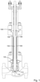
- a bellows seal valve comprises an accordion-like bellows 100.
- One end 102 of the bellows 100 is welded or otherwise attached to the valve stem 104.
- the other end 106 of the bellows 100 is welded to a part 108 that is clamped or otherwise attached to the valve bonnet 109.
- the valve stem 104 is moved in a linear valve stroke so as to control the position of a valve plug 110 relative to a valve seat 112.
- the bellows 100 compresses or expands along with the linear motion of the sliding valve stem 104.
- the bellows 100 Since the bellows 100 has a static seal at each end 102, 106, and the circumference of the valve stem 104 is covered by the bellows 100, a metal barrier between the process liquid inside of the valve and the external atmosphere is provided, eliminating leakage at the valve stem 104.
- the process liquid In the example of Fig. 1 , the process liquid is outside of the bellows 100, and the atmosphere is inside of the bellows 100.
- the process liquid is inside of the bellows 100 and the atmosphere is outside of the bellows 100. It is intrinsic to the design of a bellows valve that there is a substantial internal volume that is normally filled by the process liquid. In particular, the process liquid is generally in contact with either the inner or outer surface of the bellows 100 along its entire length.
- valve system that is configured to prevent corrosion or damage due to contact with a corrosive liquid/vapor interface, without requiring that all portions of the valve system that may potentially contact the corrosive liquid and/or its vapor be constructed from, or lined with, a material that is resistant to corrosion by the liquid/vapor interface.
- the present invention is a valve and associated corrosion control system that are configured to control a flow of a corrosive process liquid while preventing corrosion or damage due to contact with a corrosive liquid/vapor interface of the process liquid, and without requiring that all portions of the valve that may potentially contact the corrosive liquid and/or its vapor be constructed from, or lined with, a material that is resistant to corrosion by the liquid/vapor interface.
- the valve is a bellows valve.
- the valve includes a "purge port" that enables liquid communication between an internal process liquid volume of the valve that is normally filled with a corrosive process liquid and a purge line that is part of the corrosion control system.
- a backpressure of a non-reactive gas such as nitrogen gas, is established in the purge line, such that process liquid enters a vertical segment of the purge line, but is prevented from flowing beyond the vertical segment by the backpressure of the non-reactive gas.
- the corrosion control system further includes an interface level sensor that is able to sense the level of the liquid/vapor interface within the vertical segment.
- the interface level sensor is an ultrasonic sensor.
- the corrosion control system further includes a source of the non-reactive gas and a pressure regulator that is able to control the backpressure of the non-reactive gas in the vertical segment.
- Embodiments also include a controller that is configured to establish and maintain the liquid/vapor interface within the vertical segment.
- the valve when the valve is first put into service, it is initially filled and pressurized with the non-reactive gas. Then the process liquid is applied to an inlet of the valve, and the pressure of the non-reactive gas is slowly lowered, thereby allowing the corrosive process liquid to flow into the internal process liquid volume of the valve, and from thence through the purge port and into the purge line. Once the corrosive process liquid has entered the vertical segment of the purge line, the pressure of the non-reactive gas is adjusted until it reaches a backpressure that causes the liquid/vapor interface of the corrosive process liquid to be stabilized at a desired height within the vertical segment, as determined by the interface level sensor. According to the present invention, the liquid/vapor interface subsequently remains within the vertical segment during operation of the valve.
- regulation of the non-reactive gas backpressure continues during the operation of the valve, for example by causing a controller to periodically or continuously adjust a backpressure regulator according to liquid/vapor interface level measurements that are made by the interface level sensor.
- a purge valve located downstream of the vertical segment is closed, so that a fixed quantity of the non-reactive gas remains enclosed within a fixed volume of the purge line between the purge valve and the liquid/vapor interface within the vertical segment.
- liquid pressure of the corrosive process liquid fluctuates, for example due to temperature or flow rate fluctuations of the process liquid, this is accommodated, in embodiments, by a small shifting of the liquid/vapor interface level within the vertical segment as the non-reactive gas within the fixed volume is compressed or allowed to expand.
- the vertical segment is made from, or lined with, a material that is resistant to corrosion due to contact with the liquid/vapor interface.
- a material that is resistant to corrosion due to contact with the liquid/vapor interface examples include an anti-corrosion tungsten liner and a tungsten carbide thermal spray coating, among other materials and coatings. Corrosion and damage due to contact between the valve system and the liquid/vapor interface of the corrosive process liquid is thereby avoided by maintaining the liquid/vapor interface within the corrosion resistant vertical segment, without requiring that any portion of the valve or any other portion of the purge line be constructed from, or lined with, a material that is resistant to corrosion by the liquid/vapor interface of the process liquid.
- the valve further includes a heater that is configured to heat the valve, thereby maintaining a molten process substance, such as molten salt, as a liquid within the valve during normal operation.
- the heater can also be used, if needed, to re-melt the process substance if it cools and becomes solidified within the valve, for example due to a process interruption.
- valve is a bellows valve
- process liquid within the valve is molten salt that is in contact with the external side of the bellows.
- one of skill in the art will be easily able to adapt the principles of the present invention to virtually any type of valve system that controls a corrosive process liquid, including a bellows valve in which the process liquid occupies the interior of the bellows, and also including valves that are not bellows valves.
- the present invention is not limited to systems that control a flow of molten salt, but extends to all valve systems that control a flow of a corrosive liquid having a liquid/vapor interface that is more corrosive than either the liquid or the vapor when considered separately.
- the valve system includes a valve having an internal process liquid volume that is normally filled with the process liquid during operation of the valve, a purge port provided in the valve, the purge port enabling liquid communication between the internal process liquid volume and an external purge line, a vertical segment included in the purge line, said vertical segment being constructed from or lined with a material that is resistant to corrosion due to contact between the vertical segment and the liquid/vapor interface of the process liquid, an interface level sensor configured to determine a level of the liquid/vapor interface within the vertical segment, and a non-reactive gas source configured to fill a downstream segment of the purge line that is downstream of the liquid/vapor interface with a non-reactive gas having a backpressure that causes process liquid entering the purge line to enter into the vertical segment, while preventing the process liquid from flowing beyond the vertical segment
- Embodiments further include a pressure regulator configured to regulate a pressure of the non-reactive gas within the purge line.
- the liquid/vapor interface sensor can be an ultrasonic sensor.
- any of the above embodiments can further include a pressure controller that is configured to control the pressure of the non-reactive gas within the purge line so as to establish the liquid/vapor interface level within the vertical segment.
- Some of these embodiments further include an interface level controller that is configured to control the pressure controller according to measurements made by the interface level sensor so as to establish the liquid/vapor interface of the process liquid at a desired height within the vertical segment.
- Any of the above embodiments can further include a pressure sensor included in the purge line and configured to measure a pressure of the non-reactive gas within the purge line.
- Any of the above embodiments can further include a temperature sensor included in the purge line and configured to measure a temperature of the non-reactive gas in the purge line.
- Any of the above embodiments can further include a gas vent configured to vent the non-reactive gas from the purge line.
- Any of the above embodiments can further include a valve heater controlled by a heat controller.
- the valve can be a bellows valve.
- the process liquid can be molten salt.
- the material that is resistant to corrosion due to contact between the vertical segment and a liquid/vapor interface of the process liquid can include at least one of a tungsten liner and a tungsten carbide thermal spray coating applied to the vertical segment.
- a second general aspect of the present invention is a method of initializing a flow through a valve of a corrosive process liquid, a liquid/vapor interface of the process liquid being more highly corrosive than either the process liquid or the vapor thereof when considered separately.
- the method includes:
- step E) includes using the interface level sensor to determine a height of the liquid/vapor interface within the purge line. In some of these embodiments step E) includes establishing the liquid/vapor interface of the process liquid at a desired height within the vertical segment. And some of these embodiments further include, after step E), continuing to control and adjust the backpressure of the non-reactive gas within the purge line so as to maintain the liquid/vapor interface at the desired height within the vertical segment.
- any of the above embodiments can further include, after step E), closing a purge valve that is upstream of the vertical segment, thereby establishing a fixed quantity of the non-reactive gas within a fixed volume of the purge line that extends between the liquid/vapor interface and the purge valve.
- the present invention is a valve and associated corrosion control system that are configured to control a flow of a corrosive process liquid while preventing corrosion or damage due to contact with a corrosive liquid/vapor interface of the process liquid, and without requiring that all portions of the valve that may potentially contact the corrosive liquid and/or its vapor be constructed from, or lined with, a material that is resistant to corrosion by the liquid/vapor interface.
- the valve is a bellows valve.
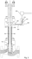
- the valve includes a "purge port" 200 that enables liquid communication between an internal process liquid volume 202 of the valve that is normally filled with the corrosive process liquid and a purge line 204 that is associated with a corrosion control system 206.
- a backpressure of a non-reactive gas such as nitrogen gas, is established in the purge line 204, such that process liquid enters a vertical segment 208 of the purge line 204, but is prevented from flowing beyond the vertical segment 208 by the backpressure of the non-reactive gas.
- the vertical segment 208 is made from, or lined with, a material that is resistant to corrosion due to contact with the liquid/vapor interface 212.
- a material that is resistant to corrosion due to contact with the liquid/vapor interface 212 examples include an anti-corrosion tungsten liner and a tungsten carbide thermal spray coating, among other materials and coatings.
- the valve system further includes an interface level sensor 210, such as an ultrasonic sensor, that is able to detect the level of the liquid/vapor interface 212 within the purge line 204.
- the backpressure of the non-reactive gas is regulated 408 to adjust the liquid/vapor interface 212 to be at a desired level within the vertical segment 208.
- the corrosion control system 206 further includes a source of 300 a non-reactive gas, such as nitrogen gas, a purge valve 312 that is configured to isolate the source 300 from the vertical segment, and a pressure regulator 302 that is able to control the pressure of the non-reactive gas in the purge line 204.
- the illustrated embodiment further includes a controller 314 that is configured to establish and maintain the liquid/vapor interface 212 within the vertical segment 208.
- the purge line 204 also includes a gas heater 304 and a gas vent 306, as well as temperature 308 and pressure 310 sensors.
- valve when the valve is put into service, it is initially filled and pressurized with the non-reactive gas 400. Then the process liquid is applied to an inlet of the valve, and the pressure of the non-reactive gas is slowly lowered 402, thereby allowing the corrosive process liquid to flow into the internal process liquid volume 202 of the valve, and from thence through the purge port 200 and into the purge line 204.
- the pressure of the non-reactive gas is adjusted 406 until it reaches a backpressure that causes the liquid/vapor interface 212 of the corrosive process liquid to be stabilized at a desired height within the vertical segment 208, as determined by the interface level sensor 210.
- the liquid/vapor interface 212 subsequently remains within the vertical segment 208 during operation of the valve.
- regulation of the non-reactive gas backpressure continues during the operation of the valve, for example by causing the controller 314 to periodically or continuously adjust the pressure regulator 302 according to liquid/vapor interface level measurements that are made by the interface level sensor 210.
- the purge valve 312 which is located downstream of the vertical segment 208, is closed 408, so that a fixed quantity of the non-reactive gas remains enclosed within a fixed volume of the purge line 204 that extends between the purge valve 312 and the liquid/vapor interface 212 within the vertical segment 208. If the liquid pressure of the corrosive process liquid fluctuates, for example due to temperature or flow rate fluctuations of the process liquid, this is normally accommodated, in embodiments, by a small shifting of the liquid/vapor interface level 212 within the vertical segment 208 as the non-reactive gas within the fixed volume is compressed or allowed to expand. In the embodiment of Fig. 4 , the controller 314 continues to monitor 410 the liquid/vapor interface level 212, as measured by the interface sensor 210, so that it can temporarily reopen the purge valve 312 and readjust the backpressure if needed.
- the vertical segment 208 is made from, or lined with, a material that is resistant to corrosion due to contact with the liquid/vapor interface 212, corrosion and damage due to contact between the valve system and the liquid/vapor interface of the corrosive process liquid is avoided, without requiring that any portion of the valve or any other portion of the purge line be constructed from, or lined with, a material that is resistant to corrosion by the liquid/vapor interface of the process liquid.
- the valve further includes a heater 500 that is configured to heat the valve, thereby maintaining a molten process substance, such as molten salt, as a liquid within the valve during normal operation.
- the heater 500 can also be used, if needed, to re-melt the process substance if it cools and becomes solidified within the valve, for example due to a process interruption.
- valve is a bellows valve
- process liquid within the valve is molten salt that is in contact with the external side of the bellows.
- one of skill in the art will be easily able to adapt the principles of the present invention to virtually any type of valve system that controls a corrosive process liquid, including a bellows valve in which the process liquid occupies the interior of the bellows, and also including valves that are not bellows valves.
- the present invention is not limited to systems that control a flow of a molten material such as molten salt, but extends to all valve systems that control a flow of a corrosive liquid having a liquid/vapor interface that is more corrosive than either of the liquid and the vapor when considered separately.
Landscapes
- Engineering & Computer Science (AREA)
- General Engineering & Computer Science (AREA)
- Mechanical Engineering (AREA)
- Physics & Mathematics (AREA)
- Life Sciences & Earth Sciences (AREA)
- Sustainable Development (AREA)
- Sustainable Energy (AREA)
- Thermal Sciences (AREA)
- Chemical & Material Sciences (AREA)
- Combustion & Propulsion (AREA)
- Lift Valve (AREA)
- Details Of Valves (AREA)
- Control Of Fluid Pressure (AREA)
Claims (15)
- Ventilsystem, das dafür ausgelegt ist, einen Strom einer korrosiven Prozessflüssigkeit (202) zu steuern, wobei eine Flüssigkeits-/Dampfschnittstelle (212) der Prozessflüssigkeit hochkorrosiver ist als entweder die Prozessflüssigkeit oder als der Dampf derselben, wenn sie gesondert betrachtet werden, wobei das Ventilsystem umfasst:ein Ventil, das ein inneres Prozessflüssigkeitsvolumen hat, das üblicherweise mit der Prozessflüssigkeit während des Betriebs des Ventils gefüllt ist;eine Spülöffnung (200), die im Ventil vorgesehen ist, wobei die Spülöffnung eine Flüssigkeitskommunikation zwischen dem inneren Prozessflüssigkeitsvolumen und einer äußeren Spülleitung (204) ermöglicht;ein vertikales Segment (208), das in der Spülleitung umfasst ist, wobei das vertikale Segment aus einem Material hergestellt oder damit ausgekleidet ist, das gegen die Korrosion beständig ist, die durch den Kontakt zwischen dem vertikalen Segment und der Flüssigkeits-/Dampfschnittstelle der Prozessflüssigkeit bedingt ist;einen Schnittstellenniveausensor (210), der dafür ausgelegt ist, ein Niveau der Flüssigkeits-/Dampfschnittstelle innerhalb des vertikalen Segments zu bestimmen; undeine nicht-reaktive Gasquelle (300), die dafür ausgelegt ist, ein stromabwärts gelegenes Segment der Spülleitung, das stromabwärts der Flüssigkeits-/Dampfschnittstelle gelegen ist, mit einem nicht-reaktiven Gas zu füllen, das einen Gegendruck hat, der bewirkt, dass die Prozessflüssigkeit, die in die Spülleitung einfließt, in das vertikale Segment einfließt, während es der Prozessflüssigkeit verhindert wird, über das vertikale Segment hinaus zu fließen.
- Ventilsystem nach Anspruch 1, ferner umfassend einen Druckregler, der dafür ausgelegt ist, einen Druck des nicht-reaktiven Gases innerhalb der Spülleitung zu regeln.
- Ventilsystem nach Anspruch 1 oder Anspruch 2, worin der Flüssigkeits-/Dampfschnittstellensensor ein Ultraschallsensor ist.
- Ventilsystem nach einem der vorhergehenden Ansprüche, ferner umfassend eine Drucksteuereinrichtung, die dafür ausgelegt ist, den Druck des nicht-reaktiven Gases innerhalb der Spülleitung so zu steuern, um das Flüssigkeits-/Dampfschnittstellenniveau innerhalb des vertikalen Segmentes festzusetzen.
- Ventilsystem nach Anspruch 4, ferner umfassend eine Schnittstellenniveausteuereinrichtung (314), die dafür ausgelegt ist, die Drucksteuereinrichtung nach Messungen zu steuern, die vom Schnittstellenniveausensor vorgenommen werden, um die Flüssigkeits-/Dampfschnittstelle der Prozessflüssigkeit bei einer gewünschten Höhe innerhalb des vertikalen Segmentes festzusetzen.
- Ventilsystem nach einem der vorhergehenden Ansprüche, ferner umfassend einen Drucksensor (310), der in der Spülleitung umfasst ist und dafür ausgelegt ist, einen Druck des nicht-reaktiven Gases innerhalb der Spülleitung zu messen.
- Ventilsystem nach einem der vorhergehenden Ansprüche, ferner umfassend einen Temperatursensor, der in der Spülleitung umfasst ist und dafür ausgelegt ist, eine Temperatur des nicht-reaktiven Gases in der Spülleitung zu messen.
- Ventilsystem nach einem der vorhergehenden Ansprüche, ferner umfassend eine Gasentlüftung (306), die dafür ausgelegt ist, das nicht-reaktive Gas aus der Spülleitung abzulassen.
- Ventilsystem nach einem der vorhergehenden Ansprüche, ferner umfassend einen Ventilheizapparat (500), der von einer Wärmesteuereinrichtung gesteuert wird.
- Ventilsystem nach einem der vorhergehenden Ansprüche, worin das Ventil ein Faltenbalgventil ist.
- Ventilsystem nach einem der vorhergehenden Ansprüche, worin das Material, das gegen die Korrosion beständig ist, die durch den Kontakt zwischen dem vertikalen Segment und einer Flüssigkeits-/Dampfschnittstelle der Prozessflüssigkeit bedingt ist, zumindest eine von einer Wolframauskleidung und einer Wolframkarbid-Wärmesprühbeschichtung umfasst, die auf das vertikale Segment aufgebracht ist.
- Verfahren zum Initialisieren eines Stroms durch ein Ventil einer korrosiven Prozessflüssigkeit, wobei eine Flüssigkeits-/Dampfschnittstelle der Prozessflüssigkeit hochkorrosiver ist als entweder die Prozessflüssigkeit oder als der Dampf derselben, wenn sie gesondert betrachtet werden, wobei das Verfahren umfasst:A) Bereitstellen eines Ventilsystems nach Anspruch 1;B) Einbringen eines nicht-reaktiven Gases in die Spülleitung, so dass das nicht-reaktive Gas das innere Prozessflüssigkeitsvolumen innerhalb des Ventils füllt;C) Aufbringen der Prozessflüssigkeit auf einen Einlass des Ventils;D) Reduzieren eines Druckes des nicht-reaktiven Gases innerhalb des Ventils, wodurch es der Prozessflüssigkeit ermöglicht wird, das innere Prozessflüssigkeitsvolumen zu füllen, und daraus durch die Spülöffnung und in die Spülleitung hinein zu fließen; undE) Festsetzen eines Gegendruckes des nicht-reaktiven Gases innerhalb der Spülleitung, der bewirkt, dass die Prozessflüssigkeit in das vertikale Segment einfließt, während es der Prozessflüssigkeit verhindert wird, über das vertikale Segment hinaus zu fließen, wodurch eine Flüssigkeits-/Dampfschnittstelle der Prozessflüssigkeit innerhalb des vertikalen Segmentes festgesetzt wird.
- Verfahren nach Anspruch 12, worin der Schritt E) das Verwenden des Schnittstellenniveausensors umfasst, um eine Höhe der Flüssigkeits-/Dampfschnittstelle innerhalb der Spülleitung zu bestimmen.
- Verfahren nach Anspruch 12 oder 13, ferner umfassend, nach dem Schritt E), das Weiter-Steuern und Einstellen des Gegendruckes des nicht-reaktiven Gases innerhalb der Spülleitung, um die Flüssigkeits-/Dampfschnittstelle bei einer gewünschten Höhe innerhalb des vertikalen Segmentes aufrechtzuerhalten.
- Verfahren nach einem der Ansprüche 12-14, ferner umfassend, nach dem Schritt E), das Schließen eines Spülventils, das stromauf des vertikalen Segmentes gelegen ist, wodurch eine feste Menge des nicht-reaktiven Gases innerhalb eines festen Volumens der Spülleitung festgesetzt wird, die sich zwischen der Flüssigkeits-/Dampfschnittstelle und dem Spülventil erstreckt.
Applications Claiming Priority (2)
| Application Number | Priority Date | Filing Date | Title |
|---|---|---|---|
| US17/485,666 US11808365B2 (en) | 2021-09-27 | 2021-09-27 | Valve system configured to prevent corrosion at process liquid/vapor interface |
| PCT/US2022/043341 WO2023048990A1 (en) | 2021-09-27 | 2022-09-13 | Valve system configured to prevent corrosion at process liquid/vapor interface |
Publications (4)
| Publication Number | Publication Date |
|---|---|
| EP4409175A1 EP4409175A1 (de) | 2024-08-07 |
| EP4409175A4 EP4409175A4 (de) | 2024-12-25 |
| EP4409175B1 true EP4409175B1 (de) | 2025-06-04 |
| EP4409175C0 EP4409175C0 (de) | 2025-06-04 |
Family
ID=85721084
Family Applications (1)
| Application Number | Title | Priority Date | Filing Date |
|---|---|---|---|
| EP22873426.5A Active EP4409175B1 (de) | 2021-09-27 | 2022-09-13 | Ventilsystem zur verhinderung von korrosion an der prozessflüssigkeits-/dampfschnittstelle |
Country Status (9)
| Country | Link |
|---|---|
| US (1) | US11808365B2 (de) |
| EP (1) | EP4409175B1 (de) |
| JP (1) | JP7591692B2 (de) |
| KR (1) | KR102663766B1 (de) |
| CN (1) | CN118019938B (de) |
| AU (1) | AU2022351537B2 (de) |
| IL (1) | IL311831A (de) |
| MX (1) | MX2024003435A (de) |
| WO (1) | WO2023048990A1 (de) |
Family Cites Families (17)
| Publication number | Priority date | Publication date | Assignee | Title |
|---|---|---|---|---|
| US2209296A (en) | 1938-12-08 | 1940-07-23 | Gasoline Prod Co Inc | Valve construction |
| US2254472A (en) | 1939-04-28 | 1941-09-02 | Mason Neilan Regulator Company | Combination control and quench valve |
| US3110319A (en) | 1962-01-15 | 1963-11-12 | Shinko Seiki Kabushiki Kaisha | High vacuum valve |
| US3120600A (en) | 1962-07-02 | 1964-02-04 | Cecil W True | Freezeless water supply |
| IT1181269B (it) * | 1984-12-10 | 1987-09-23 | Gd Spa | Metodo per la produzione contemporanea di due flussi continui di sigarette |
| JPS61139376U (de) | 1985-02-18 | 1986-08-29 | ||
| JPH0637673U (ja) * | 1992-10-19 | 1994-05-20 | 創研工業株式会社 | パージ機構によりベローズ部へのパーティクル溜まり を除去および腐食を防止した真空用およびプロセス制 御用バルブ |
| JP3769495B2 (ja) | 2001-11-26 | 2006-04-26 | Smc株式会社 | ヒーター付きポペット弁 |
| US6883534B2 (en) | 2003-08-14 | 2005-04-26 | Wcm Industries, Inc. | Freeze protection device for wall hydrants/faucets |
| US8950425B1 (en) | 2008-01-11 | 2015-02-10 | Jansen's Aircraft Systems Controls, Inc. | Combining valve with fuel relief and sealing |
| US8196893B2 (en) * | 2008-04-09 | 2012-06-12 | Mks Instruments, Inc. | Isolation valve with corrosion protected and heat transfer enhanced valve actuator and closure apparatus and method |
| US9104208B2 (en) * | 2011-08-19 | 2015-08-11 | Emerson Process Management Regulator Technologies, Inc. | Regulator with bleed valve |
| KR101580569B1 (ko) * | 2011-11-16 | 2015-12-28 | 누코프 인코포레이티드 | 원자로급 공기 축적, 표시 및 배출 장치 |
| US9255649B2 (en) | 2012-08-07 | 2016-02-09 | Fisher Controls International, Llc | Apparatus for fluid control device leak detection |
| KR101938279B1 (ko) | 2016-08-04 | 2019-01-15 | (주)제이솔루션 | 파우더 프로텍팅 다방향 밸브 |
| US11073442B2 (en) | 2017-12-21 | 2021-07-27 | Swagelok Company | Systems and methods for control and monitoring of actuated valves |
| JP7313169B2 (ja) | 2019-03-19 | 2023-07-24 | 株式会社キッツエスシーティー | 真空ベローズホットバルブ |
-
2021
- 2021-09-27 US US17/485,666 patent/US11808365B2/en active Active
-
2022
- 2022-09-13 MX MX2024003435A patent/MX2024003435A/es unknown
- 2022-09-13 CN CN202280065356.6A patent/CN118019938B/zh active Active
- 2022-09-13 KR KR1020247009379A patent/KR102663766B1/ko active Active
- 2022-09-13 IL IL311831A patent/IL311831A/en unknown
- 2022-09-13 AU AU2022351537A patent/AU2022351537B2/en active Active
- 2022-09-13 WO PCT/US2022/043341 patent/WO2023048990A1/en not_active Ceased
- 2022-09-13 EP EP22873426.5A patent/EP4409175B1/de active Active
- 2022-09-13 JP JP2024518753A patent/JP7591692B2/ja active Active
Also Published As
| Publication number | Publication date |
|---|---|
| MX2024003435A (es) | 2024-04-03 |
| US20230099720A1 (en) | 2023-03-30 |
| EP4409175A1 (de) | 2024-08-07 |
| CN118019938B (zh) | 2024-09-20 |
| US11808365B2 (en) | 2023-11-07 |
| AU2022351537A1 (en) | 2024-04-04 |
| AU2022351537B2 (en) | 2024-04-18 |
| IL311831A (en) | 2024-05-01 |
| JP7591692B2 (ja) | 2024-11-28 |
| EP4409175C0 (de) | 2025-06-04 |
| WO2023048990A1 (en) | 2023-03-30 |
| KR102663766B1 (ko) | 2024-05-03 |
| CA3233161A1 (en) | 2023-03-30 |
| KR20240042208A (ko) | 2024-04-01 |
| JP2024533719A (ja) | 2024-09-12 |
| EP4409175A4 (de) | 2024-12-25 |
| CN118019938A (zh) | 2024-05-10 |
Similar Documents
| Publication | Publication Date | Title |
|---|---|---|
| US8443830B2 (en) | Heater built-in valve | |
| TWI840534B (zh) | 調溫裝置 | |
| JP6784711B2 (ja) | 液化ガス供給装置及び液化ガス供給方法 | |
| RU2474743C2 (ru) | Устройство с двойной трубой | |
| EP4409175B1 (de) | Ventilsystem zur verhinderung von korrosion an der prozessflüssigkeits-/dampfschnittstelle | |
| CA3233161C (en) | Valve system configured to prevent corrosion at process liquid/vapor interface | |
| CN112833662A (zh) | 温度调节装置和半导体加工设备 | |
| US11692645B2 (en) | Valve with re-melting expansion port | |
| US11852262B2 (en) | Heat tracing systems for fluid valves and related methods | |
| CN214063968U (zh) | 补偿调节装置处的尺寸变化的系统、位置调整系统和调节装置 | |
| KR102876442B1 (ko) | 유체 온도 예측 장치, 그것의 구동 방법, 유체 온도 예측 장치를 포함하는 유체 온도 보정 시스템 및 유체 온도 보정 방법 | |
| RU2493461C1 (ru) | Клапан для регулирования расхода горячего газа | |
| JP2009215992A (ja) | 液体加圧ポンプの運転方法及びそのメカニカルシール | |
| JPS63275876A (ja) | 調節弁の異常検出装置 | |
| JP2024125765A (ja) | 高温流体の配管移送装置 | |
| US20220163274A1 (en) | Thermal stress management for heat exchangers, pressure vessels, and other fluid-carrying or fluid-containing structures with high temperature transients | |
| KR20250156530A (ko) | 교정방법과 외부온도 영향이 개선된 공압제어기 | |
| JP2025504868A (ja) | 媒体を能動的に減衰する補償要素、方法およびシステム | |
| CN106641428A (zh) | 恒温填料函结构 |
Legal Events
| Date | Code | Title | Description |
|---|---|---|---|
| STAA | Information on the status of an ep patent application or granted ep patent |
Free format text: STATUS: THE INTERNATIONAL PUBLICATION HAS BEEN MADE |
|
| PUAI | Public reference made under article 153(3) epc to a published international application that has entered the european phase |
Free format text: ORIGINAL CODE: 0009012 |
|
| STAA | Information on the status of an ep patent application or granted ep patent |
Free format text: STATUS: REQUEST FOR EXAMINATION WAS MADE |
|
| 17P | Request for examination filed |
Effective date: 20240328 |
|
| AK | Designated contracting states |
Kind code of ref document: A1 Designated state(s): AL AT BE BG CH CY CZ DE DK EE ES FI FR GB GR HR HU IE IS IT LI LT LU LV MC MK MT NL NO PL PT RO RS SE SI SK SM TR |
|
| A4 | Supplementary search report drawn up and despatched |
Effective date: 20241127 |
|
| RIC1 | Information provided on ipc code assigned before grant |
Ipc: F16K 41/10 20060101ALI20241121BHEP Ipc: F24S 40/40 20180101ALI20241121BHEP Ipc: F16K 41/00 20060101ALI20241121BHEP Ipc: F16K 41/02 20060101ALI20241121BHEP Ipc: F16K 49/00 20060101ALI20241121BHEP Ipc: F16K 37/00 20060101ALI20241121BHEP Ipc: F16K 25/04 20060101AFI20241121BHEP |
|
| DAV | Request for validation of the european patent (deleted) | ||
| DAX | Request for extension of the european patent (deleted) | ||
| GRAP | Despatch of communication of intention to grant a patent |
Free format text: ORIGINAL CODE: EPIDOSNIGR1 |
|
| STAA | Information on the status of an ep patent application or granted ep patent |
Free format text: STATUS: GRANT OF PATENT IS INTENDED |
|
| RIC1 | Information provided on ipc code assigned before grant |
Ipc: F16K 41/10 20060101ALI20250127BHEP Ipc: F24S 40/40 20180101ALI20250127BHEP Ipc: F16K 41/00 20060101ALI20250127BHEP Ipc: F16K 41/02 20060101ALI20250127BHEP Ipc: F16K 49/00 20060101ALI20250127BHEP Ipc: F16K 37/00 20060101ALI20250127BHEP Ipc: F16K 25/04 20060101AFI20250127BHEP |
|
| INTG | Intention to grant announced |
Effective date: 20250212 |
|
| GRAS | Grant fee paid |
Free format text: ORIGINAL CODE: EPIDOSNIGR3 |
|
| GRAA | (expected) grant |
Free format text: ORIGINAL CODE: 0009210 |
|
| STAA | Information on the status of an ep patent application or granted ep patent |
Free format text: STATUS: THE PATENT HAS BEEN GRANTED |
|
| AK | Designated contracting states |
Kind code of ref document: B1 Designated state(s): AL AT BE BG CH CY CZ DE DK EE ES FI FR GB GR HR HU IE IS IT LI LT LU LV MC MK MT NL NO PL PT RO RS SE SI SK SM TR |
|
| REG | Reference to a national code |
Ref country code: GB Ref legal event code: FG4D |
|
| REG | Reference to a national code |
Ref country code: CH Ref legal event code: EP |
|
| REG | Reference to a national code |
Ref country code: DE Ref legal event code: R096 Ref document number: 602022015664 Country of ref document: DE |
|
| REG | Reference to a national code |
Ref country code: IE Ref legal event code: FG4D |
|
| U01 | Request for unitary effect filed |
Effective date: 20250625 |
|
| U07 | Unitary effect registered |
Designated state(s): AT BE BG DE DK EE FI FR IT LT LU LV MT NL PT RO SE SI Effective date: 20250702 |
|
| PG25 | Lapsed in a contracting state [announced via postgrant information from national office to epo] |
Ref country code: ES Free format text: LAPSE BECAUSE OF FAILURE TO SUBMIT A TRANSLATION OF THE DESCRIPTION OR TO PAY THE FEE WITHIN THE PRESCRIBED TIME-LIMIT Effective date: 20250604 |
|
| PG25 | Lapsed in a contracting state [announced via postgrant information from national office to epo] |
Ref country code: NO Free format text: LAPSE BECAUSE OF FAILURE TO SUBMIT A TRANSLATION OF THE DESCRIPTION OR TO PAY THE FEE WITHIN THE PRESCRIBED TIME-LIMIT Effective date: 20250904 Ref country code: GR Free format text: LAPSE BECAUSE OF FAILURE TO SUBMIT A TRANSLATION OF THE DESCRIPTION OR TO PAY THE FEE WITHIN THE PRESCRIBED TIME-LIMIT Effective date: 20250905 |
|
| PG25 | Lapsed in a contracting state [announced via postgrant information from national office to epo] |
Ref country code: PL Free format text: LAPSE BECAUSE OF FAILURE TO SUBMIT A TRANSLATION OF THE DESCRIPTION OR TO PAY THE FEE WITHIN THE PRESCRIBED TIME-LIMIT Effective date: 20250604 |
|
| PG25 | Lapsed in a contracting state [announced via postgrant information from national office to epo] |
Ref country code: HR Free format text: LAPSE BECAUSE OF FAILURE TO SUBMIT A TRANSLATION OF THE DESCRIPTION OR TO PAY THE FEE WITHIN THE PRESCRIBED TIME-LIMIT Effective date: 20250604 |
|
| PG25 | Lapsed in a contracting state [announced via postgrant information from national office to epo] |
Ref country code: RS Free format text: LAPSE BECAUSE OF FAILURE TO SUBMIT A TRANSLATION OF THE DESCRIPTION OR TO PAY THE FEE WITHIN THE PRESCRIBED TIME-LIMIT Effective date: 20250904 |
|
| U20 | Renewal fee for the european patent with unitary effect paid |
Year of fee payment: 4 Effective date: 20250929 |
|
| PG25 | Lapsed in a contracting state [announced via postgrant information from national office to epo] |
Ref country code: IS Free format text: LAPSE BECAUSE OF FAILURE TO SUBMIT A TRANSLATION OF THE DESCRIPTION OR TO PAY THE FEE WITHIN THE PRESCRIBED TIME-LIMIT Effective date: 20251004 |
|
| PG25 | Lapsed in a contracting state [announced via postgrant information from national office to epo] |
Ref country code: SM Free format text: LAPSE BECAUSE OF FAILURE TO SUBMIT A TRANSLATION OF THE DESCRIPTION OR TO PAY THE FEE WITHIN THE PRESCRIBED TIME-LIMIT Effective date: 20250604 |
|
| PG25 | Lapsed in a contracting state [announced via postgrant information from national office to epo] |
Ref country code: CZ Free format text: LAPSE BECAUSE OF FAILURE TO SUBMIT A TRANSLATION OF THE DESCRIPTION OR TO PAY THE FEE WITHIN THE PRESCRIBED TIME-LIMIT Effective date: 20250604 |
|
| PG25 | Lapsed in a contracting state [announced via postgrant information from national office to epo] |
Ref country code: SK Free format text: LAPSE BECAUSE OF FAILURE TO SUBMIT A TRANSLATION OF THE DESCRIPTION OR TO PAY THE FEE WITHIN THE PRESCRIBED TIME-LIMIT Effective date: 20250604 |
|
| PLBE | No opposition filed within time limit |
Free format text: ORIGINAL CODE: 0009261 |
|
| STAA | Information on the status of an ep patent application or granted ep patent |
Free format text: STATUS: NO OPPOSITION FILED WITHIN TIME LIMIT |
|
| REG | Reference to a national code |
Ref country code: CH Ref legal event code: L10 Free format text: ST27 STATUS EVENT CODE: U-0-0-L10-L00 (AS PROVIDED BY THE NATIONAL OFFICE) Effective date: 20260416 |