EP4409170B1 - Druckbeaufschlagtes doppelpackungsdichtungsventil - Google Patents
Druckbeaufschlagtes doppelpackungsdichtungsventil Download PDFInfo
- Publication number
- EP4409170B1 EP4409170B1 EP22873428.1A EP22873428A EP4409170B1 EP 4409170 B1 EP4409170 B1 EP 4409170B1 EP 22873428 A EP22873428 A EP 22873428A EP 4409170 B1 EP4409170 B1 EP 4409170B1
- Authority
- EP
- European Patent Office
- Prior art keywords
- valve
- fluid
- seal
- pressurization
- pressure
- Prior art date
- Legal status (The legal status is an assumption and is not a legal conclusion. Google has not performed a legal analysis and makes no representation as to the accuracy of the status listed.)
- Active
Links
Images


Classifications
-
- F—MECHANICAL ENGINEERING; LIGHTING; HEATING; WEAPONS; BLASTING
- F16—ENGINEERING ELEMENTS AND UNITS; GENERAL MEASURES FOR PRODUCING AND MAINTAINING EFFECTIVE FUNCTIONING OF MACHINES OR INSTALLATIONS; THERMAL INSULATION IN GENERAL
- F16J—PISTONS; CYLINDERS; SEALINGS
- F16J15/00—Sealings
- F16J15/002—Sealings comprising at least two sealings in succession
- F16J15/004—Sealings comprising at least two sealings in succession forming of recuperation chamber for the leaking fluid
-
- F—MECHANICAL ENGINEERING; LIGHTING; HEATING; WEAPONS; BLASTING
- F16—ENGINEERING ELEMENTS AND UNITS; GENERAL MEASURES FOR PRODUCING AND MAINTAINING EFFECTIVE FUNCTIONING OF MACHINES OR INSTALLATIONS; THERMAL INSULATION IN GENERAL
- F16K—VALVES; TAPS; COCKS; ACTUATING-FLOATS; DEVICES FOR VENTING OR AERATING
- F16K1/00—Lift valves or globe valves, i.e. cut-off apparatus with closure members having at least a component of their opening and closing motion perpendicular to the closing faces
-
- F—MECHANICAL ENGINEERING; LIGHTING; HEATING; WEAPONS; BLASTING
- F16—ENGINEERING ELEMENTS AND UNITS; GENERAL MEASURES FOR PRODUCING AND MAINTAINING EFFECTIVE FUNCTIONING OF MACHINES OR INSTALLATIONS; THERMAL INSULATION IN GENERAL
- F16K—VALVES; TAPS; COCKS; ACTUATING-FLOATS; DEVICES FOR VENTING OR AERATING
- F16K37/00—Special means in or on valves or other cut-off apparatus for indicating or recording operation thereof, or for enabling an alarm to be given
- F16K37/0008—Mechanical means
- F16K37/0016—Mechanical means having a graduated scale
-
- F—MECHANICAL ENGINEERING; LIGHTING; HEATING; WEAPONS; BLASTING
- F16—ENGINEERING ELEMENTS AND UNITS; GENERAL MEASURES FOR PRODUCING AND MAINTAINING EFFECTIVE FUNCTIONING OF MACHINES OR INSTALLATIONS; THERMAL INSULATION IN GENERAL
- F16K—VALVES; TAPS; COCKS; ACTUATING-FLOATS; DEVICES FOR VENTING OR AERATING
- F16K37/00—Special means in or on valves or other cut-off apparatus for indicating or recording operation thereof, or for enabling an alarm to be given
- F16K37/0075—For recording or indicating the functioning of a valve in combination with test equipment
- F16K37/0091—For recording or indicating the functioning of a valve in combination with test equipment by measuring fluid parameters
-
- F—MECHANICAL ENGINEERING; LIGHTING; HEATING; WEAPONS; BLASTING
- F16—ENGINEERING ELEMENTS AND UNITS; GENERAL MEASURES FOR PRODUCING AND MAINTAINING EFFECTIVE FUNCTIONING OF MACHINES OR INSTALLATIONS; THERMAL INSULATION IN GENERAL
- F16K—VALVES; TAPS; COCKS; ACTUATING-FLOATS; DEVICES FOR VENTING OR AERATING
- F16K41/00—Spindle sealings
- F16K41/003—Spindle sealings by fluid
-
- F—MECHANICAL ENGINEERING; LIGHTING; HEATING; WEAPONS; BLASTING
- F16—ENGINEERING ELEMENTS AND UNITS; GENERAL MEASURES FOR PRODUCING AND MAINTAINING EFFECTIVE FUNCTIONING OF MACHINES OR INSTALLATIONS; THERMAL INSULATION IN GENERAL
- F16K—VALVES; TAPS; COCKS; ACTUATING-FLOATS; DEVICES FOR VENTING OR AERATING
- F16K41/00—Spindle sealings
- F16K41/02—Spindle sealings with stuffing-box ; Sealing rings
-
- F—MECHANICAL ENGINEERING; LIGHTING; HEATING; WEAPONS; BLASTING
- F16—ENGINEERING ELEMENTS AND UNITS; GENERAL MEASURES FOR PRODUCING AND MAINTAINING EFFECTIVE FUNCTIONING OF MACHINES OR INSTALLATIONS; THERMAL INSULATION IN GENERAL
- F16K—VALVES; TAPS; COCKS; ACTUATING-FLOATS; DEVICES FOR VENTING OR AERATING
- F16K41/00—Spindle sealings
- F16K41/10—Spindle sealings with diaphragm, e.g. shaped as bellows or tube
Definitions
- the invention relates to valves, and more particularly, to valves that form a seal using packing.
- a bellows seal valve is typically used.
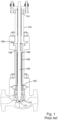
- a bellows seal valve comprises an accordion-like bellows 100 .
- One end 102 of the bellows 100 is welded or attached to the valve stem 104 .
- the other end 106 of the bellows 100 is welded to a part 108 that can be clamped or otherwise attached to the valve bonnet 109 .
- the valve stem 104 is moved in a linear valve stroke so as to control the position of a valve plug 110 relative to a valve seat 112 .
- the bellows 100 compresses or expands along with the linear motion of the sliding valve stem 104 .
- the bellows 100 has a static seal at each end 102 , 106 , and the circumference of the valve stem 104 is covered by the bellows 100 , a metal barrier between the process fluid inside of the valve and the external atmosphere is provided, eliminating leakage at the valve stem 104 .
- the process fluid is outside of the bellows 100
- the atmosphere is inside of the bellows 100 .
- the process fluid is inside of the bellows 100 and the atmosphere is outside of the bellows 100 .
- a set of packing 114 is provided above the bellows 100 to provide a second seal.
- implementing a bellows valve can be costly.
- the process fluid in the example of Fig. 1 would leak from the outside surface of the bellows 100 , through the leak path, into the inside area of the bellows 100 .
- the valve fluid would then be sealed from the outside environment only by the valve stem packing 114 in the gland area 116 of the valve. If the valve stem packing 114 were to leak, then the process fluid would escape to the outside atmosphere.
- valve stem packing 114 typically allows a higher level of leakage than a bellows 100 , there is a high probability that if the bellows 100 were to develop a leak path, at least some process fluid would escape through the bellows 100 and valve stem packing 114 to the outside environment.
- Document CN1089708A discloses a seal system, particularly suitable for process valves.
- Document US2017/292606A1 discloses a seal assembly for a valve stem.
- Document US2016/109035A1 discloses a gas pressurized packing system for control valves.
- Document US4899899A discloses a pressure vessel.
- the present invention is a reliable valve design that is less prone to leakage than conventional bellows valves, while also being less expensive than conventional bellows valves.
- a linear stroke valve includes a pair of packing seals that are spaced apart by a gap space along the valve stem, for example within a gland area of the valve. Leakage through the packing seals is prevented by introducing a pressurizing fluid, such as nitrogen, into the gap space between the packing seals and maintaining the pressurizing fluid at a gap pressure that is higher than the process fluid pressure so as to ensure that any leakage past the packing seals will be of the pressurizing fluid into the process fluid or into the environment, while any escape of the process fluid into the environment is prevented.
- a pressurizing fluid such as nitrogen
- the volume between the packing seals will normally be constant and static, and there will normally be no flow of the pressurization fluid into the valve once the desired pressure of the pressurizing fluid is established within the valve.
- the pressure and/or flow rate of the pressurizing fluid is monitored, so that any leakage of the pressurizing fluid through either or both of the packing seals is easily detected as a decrease in the pressure and/or as an increased flow rate of the pressurizing fluid into the valve.
- leakage of small amounts of the pressurizing fluid into the process fluid and/or into the environment may be tolerable.
- a maintenance action can be applied to the valve, for example by re-tightening or replacing the packing, or replacing the valve.
- the pressurizing gas can serve to protect inner rings of the packing seals by displacing oxygen away from them.
- Oxidizing resistant rings of packing can be placed on the outsides of the packing seals to protect inner rings that might otherwise be oxidized.
- this arrangement further protects the valve fluid from oxygen ingress when the process fluid is drained from the system and a vacuum is created that might otherwise suck air into the valve from the outside environment.
- One general aspect of the present invention is a valve system comprising a valve.
- the valve includes a valve seat; a valve plug configured to control a flow of process fluid through the valve according to a separation between the valve plug and the valve seat; a valve stem in mechanical communication with the valve plug and configured such that linear actuation of the valve stem controls the separation between the valve plug and the valve seat; first and second packing seals surrounding the valve stem, each of the packing seals forming a seal between the valve stem and a surrounding gland housing, the first and second packing seals being separated from each other along the valve stem by a seal gap, and a seal pressurization port configured to allow a seal pressurizing fluid to enter into the seal gap and to be pressurized within the seal gap to a desired gap pressure.
- Embodiments according to the claimed invention further include a pressurization fluid source, a pressurizing fluid pressure regulating apparatus, and a pressurization fluid line that provides fluid communication between the pressurization fluid source and the seal pressurization port of the valve. Some of these embodiments further include a pressure measuring device configured to measure a pressure of the pressurizing fluid within the gap space. Embodiments according to the claimed invention further include a flow measuring device configured to measure a flow rate of the pressurizing fluid into the gap space.
- Embodiments according to the claimed invention further include monitoring a flow rate of the pressurizing fluid and, optionally, monitoring a pressure of the pressurizing fluid
- the present invention is a reliable valve design that is less prone to leakage than conventional bellows valves, while also being less expensive than conventional bellows valves.
- the valve further includes a pressurization port 202 .
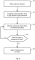
- the pressurization port 202 can be used to inject a pressurizing fluid, such as nitrogen gas 300 , through a pressurizing fluid transfer line 302 into the gap space 206 between the packing seals 114 , 200 .
- a pressure regulating device 306 is then used to establish and maintain the pressurizing fluid within the gap space 206 at a higher pressure than the process fluid, thereby ensuring that any leakage past the packing seals 114 , 200 will be of the pressurizing fluid into the process fluid and/or into the environment, while any escape of the process fluid into the environment will be prevented.
- the flow rate and, optionally, the pressure of the pressurizing fluid is monitored 404 , for example using a flow gage 304 as shown in Fig. 3 , so that any leakage of the pressurizing fluid past either or both of the packing seals 114 , 200 is easily detected and quantified as a decrease in the pressure and/or increase in the flow rate of the pressurizing fluid.
- leakage of small amounts of the pressurizing fluid into the process fluid and/or into the environment may be tolerable.
- a maintenance action can be applied 408 to the valve, for example by re-tightening or replacing one or both of the packing seals 114 , 200 , or replacing the valve.
Landscapes
- Engineering & Computer Science (AREA)
- General Engineering & Computer Science (AREA)
- Mechanical Engineering (AREA)
- Details Of Valves (AREA)
- Lift Valve (AREA)
- Valve Housings (AREA)
- Examining Or Testing Airtightness (AREA)
Claims (7)
- Ventilsystem umfassend ein Ventil, wobei das Ventil umfasst:einen Ventilsitz (112);einen Ventilstopfen (110), der dafür ausgelegt ist, einen Strom von Prozessfluid durch das Ventil gemäß einer Trennung zwischen dem Ventilstopfen (110) und dem Ventilsitz (112) zu steuern;einen Ventilschaft (104) in mechanischer Kommunikation mit dem Ventilstopfen (110) und derart ausgelegt, dass eine lineare Betätigung des Ventilschafts (104) die Trennung zwischen dem Ventilstopfen (110) und dem Ventilsitz (112) steuert;erste und zweite Packungsdichtungen (114, 200), die den Ventilschaft (104) umgeben, wobei jeder von den Packungsdichtungen (114, 200) eine Dichtung zwischen dem Ventilschaft (104) und einem umgebenden Stopfbuchsgehäuse bildet, wobei die ersten und zweiten Packungsdichtungen (114, 200) voneinander entlang des Ventilschafts durch einen Dichtungsspalt (206) getrennt sind;eine Dichtungsdruckbeaufschlagungsöffnung (202), die dafür ausgelegt ist, dass einem Dichtungsdruckbeaufschlagungsfluid ermöglicht wird, in den Dichtungsspalt (206) einzutreten und innerhalb des Dichtungsspalts (206) auf einen gewünschten Spaltdruck mit Druck beaufschlagt zu werden;eine Druckbeaufschlagungsfluidquelle (300);einen Druckbeaufschlagungsfluid-Druckregelungsapparat (306) und eine Druckbeaufschlagungsfluidleitung (302), die eine Fluidkommunikation zwischen der Druckbeaufschlagungsfluidquelle (300) und der Dichtungsdruckbeaufschlagungsöffnung (202) des Ventils liefert;eine Durchflussmessvorrichtung (304), die dafür ausgelegt ist, eine Durchflussmenge des Druckbeaufschlagungsfluids in den Dichtungsspalt (206) hinein zu messen, wobei die Druckbeaufschlagungsfluidleitung (302) uneingeschränkt zwischen dem Druckbeaufschlagungsfluid-Druckregelungsapparat (306) und der Dichtungsdruckbeaufschlagungsöffnung (202) des Ventils ist.
- Ventilsystem nach Anspruch 1, ferner umfassend eine Druckmessvorrichtung, die dafür ausgelegt ist, einen Druck des Druckbeaufschlagungsfluids innerhalb des Dichtungsspaltes (206) zu messen.
- Verfahren zum Verhindern von Prozessfluidaustritt entlang eines Ventilschaftes eines linearen Hubventils, wobei das Verfahren umfasst:Bereitstellen eines Ventilsystems umfassend:einen Ventilsitz (112);einen Ventilstopfen (110), der dafür ausgelegt ist, einen Strom von Prozessfluid durch das Ventil gemäß einer Trennung zwischen dem Ventilstopfen (110) und dem Ventilsitz (112) zu steuern;einen Ventilschaft (104) in mechanischer Kommunikation mit dem Ventilstopfen (110) und derart ausgelegt, dass eine lineare Betätigung des Ventilschafts (104) die Trennung zwischen dem Ventilstopfen (110) und dem Ventilsitz (112) steuert;erste und zweite Packungsdichtungen (114, 200), die den Ventilschaft (104) umgeben, wobei jeder von den Packungsdichtungen (114, 200) eine Dichtung zwischen dem Ventilschaft (104) und einem umgebenden Stopfbuchsgehäuse bildet, wobei die ersten und zweiten Packungsdichtungen (114, 200) voneinander entlang des Ventilschafts durch einen Dichtungsspalt (206) getrennt sind;eine Dichtungsdruckbeaufschlagungsöffnung (202), die dafür ausgelegt ist, dass einem Dichtungsdruckbeaufschlagungsfluid ermöglicht wird, in den Dichtungsspalt (206) einzutreten und innerhalb des Dichtungsspalts (206) auf einen gewünschten Spaltdruck mit Druck beaufschlagt zu werden;eine Druckbeaufschlagungsfluidquelle (300);einen Druckbeaufschlagungsfluid-Druckregelungsapparat (306) und eine Druckbeaufschlagungsfluidleitung (302), die eine Fluidkommunikation zwischen der Druckbeaufschlagungsfluidquelle (300) und der Dichtungsdruckbeaufschlagungsöffnung (202) des Ventils liefert; undeine Durchflussmessvorrichtung (304), die dafür ausgelegt ist, eine Durchflussmenge des Druckbeaufschlagungsfluids in den Dichtungsspalt (206) hinein zu messen, wobei die Druckbeaufschlagungsfluidleitung (302) uneingeschränkt zwischen dem Druckbeaufschlagungsfluid-Druckregelungsapparat (306) und der Dichtungsdruckbeaufschlagungsöffnung (202) des Ventils ist;Bestimmen oder Schätzen eines Prozessdruckes des Prozessfluids; undAufbringen eines Druckbeaufschlagungsfluids auf die Dichtungsdruckbeaufschlagungsöffnung (202), wobei das Druckbeaufschlagungsfluid auf einen Spaltdruck mit Druck beaufschlagt wird, der höher ist als der Prozessdruck;Überwachen einer Durchflussmenge des Druckbeaufschlagungsfluids; undwenn die überwachte Durchflussmenge sich um mehr als eine festgelegte Menge ändert, Bestimmen, dass ein Austritt sich im Ventil entwickelt hat, und Anwenden eines Wartungseinsatzes auf das Ventil.
- Verfahren nach Anspruch 3, ferner umfassend das Überwachen eines Druckes des Druckbeaufschlagungsfluids.
- Verfahren nach Anspruch 4, ferner umfassend, wenn der überwachte Druck sich um mehr als eine festgelegte Menge ändert, Bestimmen, dass ein Austritt sich im Ventil entwickelt hat, und Anwenden eines Wartungseinsatzes auf das Ventil.
- Verfahren nach Anspruch 5, worin der Wartungseinsatz zumindest eines von Folgenden umfasst:Nachziehen von zumindest einer der Packungsdichtungen (114, 200);Ersetzen von zumindest einer der Packungsdichtungen (114, 200); undErsetzen des Ventils.
- Verfahren nach einem der Ansprüche 3-6, worin das Druckbeaufschlagungsfluid Stickstoffgas ist.
Applications Claiming Priority (2)
| Application Number | Priority Date | Filing Date | Title |
|---|---|---|---|
| US17/485,674 US11774004B2 (en) | 2021-09-27 | 2021-09-27 | Pressurized dual packing seal valve |
| PCT/US2022/043349 WO2023048992A1 (en) | 2021-09-27 | 2022-09-13 | Pressurized dual packing seal valve |
Publications (4)
| Publication Number | Publication Date |
|---|---|
| EP4409170A1 EP4409170A1 (de) | 2024-08-07 |
| EP4409170A4 EP4409170A4 (de) | 2024-12-25 |
| EP4409170C0 EP4409170C0 (de) | 2025-07-02 |
| EP4409170B1 true EP4409170B1 (de) | 2025-07-02 |
Family
ID=85718090
Family Applications (1)
| Application Number | Title | Priority Date | Filing Date |
|---|---|---|---|
| EP22873428.1A Active EP4409170B1 (de) | 2021-09-27 | 2022-09-13 | Druckbeaufschlagtes doppelpackungsdichtungsventil |
Country Status (10)
| Country | Link |
|---|---|
| US (1) | US11774004B2 (de) |
| EP (1) | EP4409170B1 (de) |
| JP (1) | JP2024536857A (de) |
| KR (1) | KR20240042550A (de) |
| CN (1) | CN118019937A (de) |
| AU (1) | AU2022352114B2 (de) |
| CA (1) | CA3232309A1 (de) |
| IL (1) | IL311822A (de) |
| MX (1) | MX2024003432A (de) |
| WO (1) | WO2023048992A1 (de) |
Family Cites Families (22)
| Publication number | Priority date | Publication date | Assignee | Title |
|---|---|---|---|---|
| US3776558A (en) * | 1972-03-17 | 1973-12-04 | Exxon Production Research Co | Tandem packing for a reciprocating pump |
| US4270760A (en) * | 1979-10-15 | 1981-06-02 | Greiman Myrl H W | Sealing assembly |
| US4451047A (en) * | 1981-07-31 | 1984-05-29 | Smith International, Inc. | Seal |
| US4878677A (en) * | 1988-12-15 | 1989-11-07 | Hydrochem Developments Ltd. | Shut off seal about a shaft of a device having a side entry into a tank |
| US4899899A (en) * | 1989-06-21 | 1990-02-13 | Triten Corporation | Pressure vessel |
| US5290046A (en) * | 1992-07-08 | 1994-03-01 | Houston James L | Internal live loading packing gland |
| JP2573645Y2 (ja) * | 1992-07-23 | 1998-06-04 | 山武ハネウエル株式会社 | 弁装置 |
| IT1255676B (it) | 1992-10-09 | 1995-11-10 | Giorgio Bergamini | Sistema perfezionato di tenuta, particolarmente adatto per valvole di processo |
| US5540253A (en) * | 1994-11-16 | 1996-07-30 | Triten Corporation | Plug valve |
| JP3334066B2 (ja) * | 1995-03-30 | 2002-10-15 | 株式会社山武 | 弁装置 |
| US20010032952A1 (en) * | 2000-01-14 | 2001-10-25 | Ruben Lah | Floating stuffing box assembly |
| JP4688117B2 (ja) * | 2000-04-10 | 2011-05-25 | 株式会社アルバック | 爆発性または発火性ガスに対するシール機構 |
| EP1217352A1 (de) | 2000-12-20 | 2002-06-26 | ABBPATENT GmbH | Verfahren und Einrichtung zur Ermittlung von Leckagen an der Dichtung eines Ventils |
| JP2002213618A (ja) * | 2001-01-23 | 2002-07-31 | Toyota Motor Corp | シール構造、シール異状検出方法、加熱炉のシール構造、加熱炉のシール異状検出方法 |
| US7118114B2 (en) * | 2003-05-15 | 2006-10-10 | Woodward Governor Company | Dynamic sealing arrangement for movable shaft |
| US20050151107A1 (en) * | 2003-12-29 | 2005-07-14 | Jianchao Shu | Fluid control system and stem joint |
| JP5982375B2 (ja) * | 2011-07-29 | 2016-08-31 | Ckd株式会社 | 流体制御弁 |
| US9528607B2 (en) * | 2011-12-01 | 2016-12-27 | Garlock Sealing Technologies, Llc | Stuffing box flow diverter and methods therefor |
| CN105339789B (zh) * | 2013-03-11 | 2017-03-29 | 机械解析有限公司 | 具有密封组件的隔膜阀、包括隔膜阀的色谱系统及其操作方法 |
| US9528631B2 (en) | 2014-10-21 | 2016-12-27 | Fisher Controls International Llc | Gas pressurized packing system for control valves |
| GB201419795D0 (en) | 2014-11-06 | 2014-12-24 | Aes Eng Ltd | Mechanical seal support system |
| ITMI20142265A1 (it) | 2014-12-29 | 2016-06-29 | Nuovo Pignone Srl | Dispositivo di tenuta per lo stelo di una valvola |
-
2021
- 2021-09-27 US US17/485,674 patent/US11774004B2/en active Active
-
2022
- 2022-09-13 WO PCT/US2022/043349 patent/WO2023048992A1/en not_active Ceased
- 2022-09-13 JP JP2024518766A patent/JP2024536857A/ja active Pending
- 2022-09-13 CA CA3232309A patent/CA3232309A1/en active Pending
- 2022-09-13 EP EP22873428.1A patent/EP4409170B1/de active Active
- 2022-09-13 CN CN202280065391.8A patent/CN118019937A/zh active Pending
- 2022-09-13 IL IL311822A patent/IL311822A/en unknown
- 2022-09-13 AU AU2022352114A patent/AU2022352114B2/en active Active
- 2022-09-13 MX MX2024003432A patent/MX2024003432A/es unknown
- 2022-09-13 KR KR1020247009409A patent/KR20240042550A/ko active Pending
Also Published As
| Publication number | Publication date |
|---|---|
| IL311822A (en) | 2024-05-01 |
| EP4409170C0 (de) | 2025-07-02 |
| AU2022352114A1 (en) | 2024-04-04 |
| AU2022352114B2 (en) | 2025-06-12 |
| WO2023048992A1 (en) | 2023-03-30 |
| CA3232309A1 (en) | 2023-03-30 |
| JP2024536857A (ja) | 2024-10-08 |
| MX2024003432A (es) | 2024-04-03 |
| US20230096922A1 (en) | 2023-03-30 |
| KR20240042550A (ko) | 2024-04-02 |
| EP4409170A4 (de) | 2024-12-25 |
| US11774004B2 (en) | 2023-10-03 |
| CN118019937A (zh) | 2024-05-10 |
| EP4409170A1 (de) | 2024-08-07 |
Similar Documents
| Publication | Publication Date | Title |
|---|---|---|
| KR101844612B1 (ko) | 회수가능한 압력 센서 | |
| US10359113B2 (en) | Seal assembly for a valve stem | |
| EP3057111A1 (de) | Druckkompensator und verfahren zur herstellung eines druckkompensators | |
| US20200056954A1 (en) | Overpressure protection system | |
| EP4409170B1 (de) | Druckbeaufschlagtes doppelpackungsdichtungsventil | |
| US4537385A (en) | Low emission valve | |
| US5941530A (en) | Unidirectional environment barrier seal for subsea wellhead equipment and valves | |
| US10533669B2 (en) | Bi-directional flow control valve | |
| EP1333187B1 (de) | Absaug- und kontrollvorrichtung einer mehrstufigen labyrinthdichtung eines im vakuum verwendeten hydrostatischen lagers | |
| EP4409177B1 (de) | Druckkompensiertes balgventil | |
| EP3428492B1 (de) | Verschlusskappe | |
| US11467056B2 (en) | Sensing leak in a multi-seal sealing assembly with sensors | |
| KR102922740B1 (ko) | 압력 보상형 벨로우즈 밸브 | |
| US9759624B2 (en) | Pressure transducer with case vent to avoid catastrophic failure | |
| CN107208810A (zh) | 衬里型蝶形阀 | |
| WO1998021508A1 (en) | Uni-directional environmental barrier seal | |
| Buck | Pressure ratings of mechanical seals | |
| CN107559468A (zh) | 介质压力可控的高密封性阀门 |
Legal Events
| Date | Code | Title | Description |
|---|---|---|---|
| STAA | Information on the status of an ep patent application or granted ep patent |
Free format text: STATUS: THE INTERNATIONAL PUBLICATION HAS BEEN MADE |
|
| PUAI | Public reference made under article 153(3) epc to a published international application that has entered the european phase |
Free format text: ORIGINAL CODE: 0009012 |
|
| STAA | Information on the status of an ep patent application or granted ep patent |
Free format text: STATUS: REQUEST FOR EXAMINATION WAS MADE |
|
| 17P | Request for examination filed |
Effective date: 20240328 |
|
| AK | Designated contracting states |
Kind code of ref document: A1 Designated state(s): AL AT BE BG CH CY CZ DE DK EE ES FI FR GB GR HR HU IE IS IT LI LT LU LV MC MK MT NL NO PL PT RO RS SE SI SK SM TR |
|
| A4 | Supplementary search report drawn up and despatched |
Effective date: 20241127 |
|
| RIC1 | Information provided on ipc code assigned before grant |
Ipc: F16K 37/00 20060101ALI20241121BHEP Ipc: F16K 17/02 20060101ALI20241121BHEP Ipc: F16K 1/42 20060101ALI20241121BHEP Ipc: F16K 1/36 20060101ALI20241121BHEP Ipc: F16K 1/46 20060101AFI20241121BHEP |
|
| DAV | Request for validation of the european patent (deleted) | ||
| DAX | Request for extension of the european patent (deleted) | ||
| GRAP | Despatch of communication of intention to grant a patent |
Free format text: ORIGINAL CODE: EPIDOSNIGR1 |
|
| STAA | Information on the status of an ep patent application or granted ep patent |
Free format text: STATUS: GRANT OF PATENT IS INTENDED |
|
| INTG | Intention to grant announced |
Effective date: 20250402 |
|
| GRAS | Grant fee paid |
Free format text: ORIGINAL CODE: EPIDOSNIGR3 |
|
| GRAA | (expected) grant |
Free format text: ORIGINAL CODE: 0009210 |
|
| STAA | Information on the status of an ep patent application or granted ep patent |
Free format text: STATUS: THE PATENT HAS BEEN GRANTED |
|
| AK | Designated contracting states |
Kind code of ref document: B1 Designated state(s): AL AT BE BG CH CY CZ DE DK EE ES FI FR GB GR HR HU IE IS IT LI LT LU LV MC MK MT NL NO PL PT RO RS SE SI SK SM TR |
|
| REG | Reference to a national code |
Ref country code: GB Ref legal event code: FG4D |
|
| REG | Reference to a national code |
Ref country code: CH Ref legal event code: EP |
|
| REG | Reference to a national code |
Ref country code: DE Ref legal event code: R096 Ref document number: 602022017111 Country of ref document: DE |
|
| REG | Reference to a national code |
Ref country code: IE Ref legal event code: FG4D |
|
| U01 | Request for unitary effect filed |
Effective date: 20250717 |
|
| U07 | Unitary effect registered |
Designated state(s): AT BE BG DE DK EE FI FR IT LT LU LV MT NL PT RO SE SI Effective date: 20250724 |
|
| U20 | Renewal fee for the european patent with unitary effect paid |
Year of fee payment: 4 Effective date: 20250929 |
|
| PG25 | Lapsed in a contracting state [announced via postgrant information from national office to epo] |
Ref country code: IS Free format text: LAPSE BECAUSE OF FAILURE TO SUBMIT A TRANSLATION OF THE DESCRIPTION OR TO PAY THE FEE WITHIN THE PRESCRIBED TIME-LIMIT Effective date: 20251102 |
|
| PG25 | Lapsed in a contracting state [announced via postgrant information from national office to epo] |
Ref country code: NO Free format text: LAPSE BECAUSE OF FAILURE TO SUBMIT A TRANSLATION OF THE DESCRIPTION OR TO PAY THE FEE WITHIN THE PRESCRIBED TIME-LIMIT Effective date: 20251002 |
|
| PG25 | Lapsed in a contracting state [announced via postgrant information from national office to epo] |
Ref country code: HR Free format text: LAPSE BECAUSE OF FAILURE TO SUBMIT A TRANSLATION OF THE DESCRIPTION OR TO PAY THE FEE WITHIN THE PRESCRIBED TIME-LIMIT Effective date: 20250702 |
|
| PG25 | Lapsed in a contracting state [announced via postgrant information from national office to epo] |
Ref country code: GR Free format text: LAPSE BECAUSE OF FAILURE TO SUBMIT A TRANSLATION OF THE DESCRIPTION OR TO PAY THE FEE WITHIN THE PRESCRIBED TIME-LIMIT Effective date: 20251003 |
|
| PG25 | Lapsed in a contracting state [announced via postgrant information from national office to epo] |
Ref country code: CZ Free format text: LAPSE BECAUSE OF FAILURE TO SUBMIT A TRANSLATION OF THE DESCRIPTION OR TO PAY THE FEE WITHIN THE PRESCRIBED TIME-LIMIT Effective date: 20250702 |
|
| PG25 | Lapsed in a contracting state [announced via postgrant information from national office to epo] |
Ref country code: PL Free format text: LAPSE BECAUSE OF FAILURE TO SUBMIT A TRANSLATION OF THE DESCRIPTION OR TO PAY THE FEE WITHIN THE PRESCRIBED TIME-LIMIT Effective date: 20250702 |
|
| PG25 | Lapsed in a contracting state [announced via postgrant information from national office to epo] |
Ref country code: RS Free format text: LAPSE BECAUSE OF FAILURE TO SUBMIT A TRANSLATION OF THE DESCRIPTION OR TO PAY THE FEE WITHIN THE PRESCRIBED TIME-LIMIT Effective date: 20251002 |
|
| PG25 | Lapsed in a contracting state [announced via postgrant information from national office to epo] |
Ref country code: ES Free format text: LAPSE BECAUSE OF FAILURE TO SUBMIT A TRANSLATION OF THE DESCRIPTION OR TO PAY THE FEE WITHIN THE PRESCRIBED TIME-LIMIT Effective date: 20250702 |