EP4409113B1 - Hochdruck-gasturbine für eine turbomaschine und turbomaschine - Google Patents
Hochdruck-gasturbine für eine turbomaschine und turbomaschine Download PDFInfo
- Publication number
- EP4409113B1 EP4409113B1 EP22786057.4A EP22786057A EP4409113B1 EP 4409113 B1 EP4409113 B1 EP 4409113B1 EP 22786057 A EP22786057 A EP 22786057A EP 4409113 B1 EP4409113 B1 EP 4409113B1
- Authority
- EP
- European Patent Office
- Prior art keywords
- upstream
- annular
- downstream
- radially
- deflector
- Prior art date
- Legal status (The legal status is an assumption and is not a legal conclusion. Google has not performed a legal analysis and makes no representation as to the accuracy of the status listed.)
- Active
Links
Images

Classifications
-
- F—MECHANICAL ENGINEERING; LIGHTING; HEATING; WEAPONS; BLASTING
- F01—MACHINES OR ENGINES IN GENERAL; ENGINE PLANTS IN GENERAL; STEAM ENGINES
- F01D—NON-POSITIVE DISPLACEMENT MACHINES OR ENGINES, e.g. STEAM TURBINES
- F01D11/00—Preventing or minimising internal leakage of working-fluid, e.g. between stages
- F01D11/001—Preventing or minimising internal leakage of working-fluid, e.g. between stages for sealing space between stator blade and rotor
-
- F—MECHANICAL ENGINEERING; LIGHTING; HEATING; WEAPONS; BLASTING
- F01—MACHINES OR ENGINES IN GENERAL; ENGINE PLANTS IN GENERAL; STEAM ENGINES
- F01D—NON-POSITIVE DISPLACEMENT MACHINES OR ENGINES, e.g. STEAM TURBINES
- F01D11/00—Preventing or minimising internal leakage of working-fluid, e.g. between stages
- F01D11/02—Preventing or minimising internal leakage of working-fluid, e.g. between stages by non-contact sealings, e.g. of labyrinth type
-
- F—MECHANICAL ENGINEERING; LIGHTING; HEATING; WEAPONS; BLASTING
- F01—MACHINES OR ENGINES IN GENERAL; ENGINE PLANTS IN GENERAL; STEAM ENGINES
- F01D—NON-POSITIVE DISPLACEMENT MACHINES OR ENGINES, e.g. STEAM TURBINES
- F01D9/00—Stators
- F01D9/02—Nozzles; Nozzle boxes; Stator blades; Guide conduits, e.g. individual nozzles
- F01D9/04—Nozzles; Nozzle boxes; Stator blades; Guide conduits, e.g. individual nozzles forming ring or sector
- F01D9/041—Nozzles; Nozzle boxes; Stator blades; Guide conduits, e.g. individual nozzles forming ring or sector using blades
-
- F—MECHANICAL ENGINEERING; LIGHTING; HEATING; WEAPONS; BLASTING
- F01—MACHINES OR ENGINES IN GENERAL; ENGINE PLANTS IN GENERAL; STEAM ENGINES
- F01D—NON-POSITIVE DISPLACEMENT MACHINES OR ENGINES, e.g. STEAM TURBINES
- F01D11/00—Preventing or minimising internal leakage of working-fluid, e.g. between stages
- F01D11/02—Preventing or minimising internal leakage of working-fluid, e.g. between stages by non-contact sealings, e.g. of labyrinth type
- F01D11/04—Preventing or minimising internal leakage of working-fluid, e.g. between stages by non-contact sealings, e.g. of labyrinth type using sealing fluid, e.g. steam
-
- F—MECHANICAL ENGINEERING; LIGHTING; HEATING; WEAPONS; BLASTING
- F05—INDEXING SCHEMES RELATING TO ENGINES OR PUMPS IN VARIOUS SUBCLASSES OF CLASSES F01-F04
- F05D—INDEXING SCHEME FOR ASPECTS RELATING TO NON-POSITIVE-DISPLACEMENT MACHINES OR ENGINES, GAS-TURBINES OR JET-PROPULSION PLANTS
- F05D2220/00—Application
- F05D2220/30—Application in turbines
- F05D2220/32—Application in turbines in gas turbines
- F05D2220/321—Application in turbines in gas turbines for a special turbine stage
- F05D2220/3212—Application in turbines in gas turbines for a special turbine stage the first stage of a turbine
-
- F—MECHANICAL ENGINEERING; LIGHTING; HEATING; WEAPONS; BLASTING
- F05—INDEXING SCHEMES RELATING TO ENGINES OR PUMPS IN VARIOUS SUBCLASSES OF CLASSES F01-F04
- F05D—INDEXING SCHEME FOR ASPECTS RELATING TO NON-POSITIVE-DISPLACEMENT MACHINES OR ENGINES, GAS-TURBINES OR JET-PROPULSION PLANTS
- F05D2240/00—Components
- F05D2240/10—Stators
- F05D2240/12—Fluid guiding means, e.g. vanes
- F05D2240/126—Baffles or ribs
-
- F—MECHANICAL ENGINEERING; LIGHTING; HEATING; WEAPONS; BLASTING
- F05—INDEXING SCHEMES RELATING TO ENGINES OR PUMPS IN VARIOUS SUBCLASSES OF CLASSES F01-F04
- F05D—INDEXING SCHEME FOR ASPECTS RELATING TO NON-POSITIVE-DISPLACEMENT MACHINES OR ENGINES, GAS-TURBINES OR JET-PROPULSION PLANTS
- F05D2240/00—Components
- F05D2240/10—Stators
- F05D2240/12—Fluid guiding means, e.g. vanes
- F05D2240/127—Vortex generators, turbulators, or the like, for mixing
-
- F—MECHANICAL ENGINEERING; LIGHTING; HEATING; WEAPONS; BLASTING
- F05—INDEXING SCHEMES RELATING TO ENGINES OR PUMPS IN VARIOUS SUBCLASSES OF CLASSES F01-F04
- F05D—INDEXING SCHEME FOR ASPECTS RELATING TO NON-POSITIVE-DISPLACEMENT MACHINES OR ENGINES, GAS-TURBINES OR JET-PROPULSION PLANTS
- F05D2250/00—Geometry
- F05D2250/10—Two-dimensional
- F05D2250/18—Two-dimensional patterned
- F05D2250/185—Two-dimensional patterned serpentine-like
Definitions
- the present invention relates to a high-pressure gas turbine for a turbomachine. It also relates to a turbomachine comprising such a gas turbine.
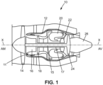
- a turbomachine 10 of the double-flow turbojet type comprises, from upstream to downstream in the direction of circulation of the gases inside the turbomachine 10, a fan 14, a low-pressure compressor 16, a high-pressure compressor 18, a combustion chamber 20, a high-pressure turbine 22, a low-pressure turbine 24 and an exhaust nozzle 26.
- the low-pressure compressor 16, the high-pressure compressor 18, the combustion chamber 20, the high-pressure turbine 22, the low-pressure turbine 24 and the exhaust nozzle 26 are arranged radially inside a casing 12 which delimits, radially outwards, an annular vein 11 of the turbomachine 10 in which the gases flow from upstream to downstream.
- the high-pressure compressor 14 and the low-pressure compressor 18 are respectively connected to a high-pressure turbine 22 and a low-pressure turbine 24 by a respective shaft 15, 17 extending along the longitudinal axis X of rotation of the shafts of the turbomachine 10.
- orientation qualifiers such as “longitudinal”, “radial” and “circumferential” are defined with reference to the longitudinal axis.
- upstream and downstream are defined with respect to the direction of circulation of the gases within the turbomachine.
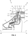
- the high-pressure turbine 22 comprises a plurality of stages, one of which is partially shown in FIG. Figure 2 , each comprising a distributor 30 and a mobile wheel 40 mounted downstream of the distributor 30.
- the distributor 30 comprises an internal annular platform 34 and an annular row of fixed blades 32. Each fixed blade 32 extends radially in the annular vein 11 and is connected, radially inside, to the internal annular platform 34.
- the distributor 30 generally comprises an annular radial flange 36 for attachment to the casing 5.
- the mobile wheel 40 comprises an annular row of mobile blades 42 carried by a disc 41 comprising a plurality of cells on its external periphery, each receiving a root 46 of a blade 42.
- Each mobile blade 42 further comprises a sector of a internal annular platform 44 of the mobile wheel 40 from which a blade 42' extends radially outwards through the annular vein 11.
- the internal annular platform 44 thus comprises a plurality of sectors arranged circumferentially end to end around the longitudinal axis X.
- the internal annular platform 34 of the distributor 30 and the internal annular platform 44 of the moving wheel 40 each delimit, radially inwards, the annular vein 11.
- the gases flowing in the annular vein 11 are introduced into a space formed longitudinally between the internal annular platform 34 of the distributor 30 and the internal annular platform 44 of the moving wheel 40, which reduces the performance of the turbomachine 10.
- a baffle is formed in the longitudinal space between the internal annular platform 34 of the distributor 30 and the internal annular platform 44 of the moving wheel 44, limiting the leakage, radially inwards, of the gases flowing in the annular vein 11.
- the annular part 50 comprises a cavity 51 in which an elastic member 51' is housed.
- a purge air flow taken from the low-pressure compressor 14 and/or the high-pressure compressor 16, is directed through an annular purge cavity 62 towards the space formed longitudinally between the internal annular platform 34 of the distributor 30 and the internal annular platform 44 of the mobile wheel 4.
- This purge air flow thus makes it possible to redirect the gases that have entered the purge cavity 62 towards the annular vein 11.
- the present invention improves the situation.
- the double baffle generates a pressure drop that limits the gas leakage flow rate from the vein radially inwards, between the distributor and the annular row of moving blades, also limiting the necessary air purge flow rate. Furthermore, the upstream annular cavity also limits such a leakage flow rate, by creating an additional pressure drop.
- the bleed air flow rate required to redirect the hot gases that have entered between the distributor and the annular row of moving blades towards the annular flow path is reduced.
- the elements of the annular row of moving blades are better protected.
- the quantity of bleed air taken from the high-pressure compressor and/or the low-pressure compressor is reduced, which improves the overall efficiency of the turbomachine and therefore reduces the specific consumption.
- a so-called annular part may comprise a plurality of sectors arranged circumferentially end to end around an axis, in particular at 360° around said axis.
- a so-called annular part may also be a single piece, i.e. formed from a single piece and not from sectors.
- the first upstream spoiler, the second upstream spoiler and/or the downstream spoiler may be, at least in part, cylindrical.
- the first upstream spoiler may have a radially external face which is of truncated cone shape with a section decreasing towards the upstream extending over at least a first longitudinal portion.
- Such a shape facilitates the evacuation of purge air and gases from the cavity between the distributor and the annular row of moving blades into the annular vein. Furthermore, such a feature allows the direction in which the gases mixed in the annular vein are reintroduced into the annular vein to be adapted to minimize disturbances to the gases flowing in the annular vein.
- the annular space extending between the first and second upstream spoilers is delimited by a radially inner surface of the first upstream spoiler, a radially outer surface of the second upstream spoiler and a concave upstream surface of the downstream sealing part.
- the radially internal surface of the second upstream spoiler can be connected to an upstream face of the downstream sealing part by a concave rounded portion.
- the upstream annular cavity of the upstream sealing part may be delimited longitudinally by a downstream radial face of the distributor and by a downstream radial wall of the upstream sealing part extending radially outward from the annular portion of the upstream sealing part portion, and delimited radially by an annular end surface located at the radially outer end of said annular portion and by a longitudinal wall extending longitudinally upstream from the radially outer end of the downstream radial wall, said external annular clearance being formed longitudinally between the downstream radial face of the distributor and the upstream end of said longitudinal wall.
- Said annular end surface may comprise a frustoconical zone widening downstream.
- the radially inner annular face of the inner annular platform of the distributor may have at least one concave-shaped area.
- the distributor may further comprise a radial annular flange extending radially inwardly from the inner annular platform, the upstream sealing part being attached and fixed to the radial annular flange.
- the present invention also relates to a turbomachine comprising a high-pressure gas turbine of the aforementioned type.
- FIG. 3 and 4 represent, according to a first embodiment, partially a high-pressure turbine of a turbomachine with longitudinal axis X.
- the high-pressure turbine comprises a plurality of stages each comprising a distributor 30 and a mobile wheel 40 mounted downstream of the distributor 30.
- the distributor 30 comprises an annular row of fixed blades 32.
- Each fixed blade 32 is connected, radially inward, to an inner annular platform 34 of the distributor 30.
- Each fixed blade 32 extends radially outward from the inner annular platform 34.
- Each fixed blade 32 is connected, radially outward, to an outer platform 34' connected to an outer casing of the high-pressure turbine.
- a radially outer annular face of the inner annular platform 34 and a radially inner annular face of the outer platform 34' delimit, radially, respectively inwardly and outwardly, an annular vein 11 of the turbomachine 10 at the distributor 30 of the high-pressure turbine.
- each fixed blade 32 extends radially inside the annular vein 11.
- the distributor 30 further comprises a radial annular flange 36 extending radially inward from the internal annular platform 34.
- the distributor 30 can be connected to an internal turbomachine casing via the radial annular flange 36.
- the movable wheel 40 comprises an annular row of movable blades 42 carried by a disc 41.
- the movable wheel 40 comprises an internal annular platform 44.
- Each movable blade 42 of the movable wheel 40 comprises a sector of the internal annular platform 44, the sectors being arranged circumferentially end to end around the longitudinal axis X.
- a radially external annular face 44a of the internal annular platform 44 delimits, radially inwards, the annular vein 11 at the movable wheel 40 of the turbine.
- Each movable blade 42 comprises a blade 42' extending, radially outwards, into the annular vein 11 from the respective sector of the internal annular platform 44.
- the movable wheel 40 also comprises a downstream sealing part 43 attached and fixed to an upstream radial surface of the disc 41 and of the zone comprising the platform 44.
- the downstream sealing part 43 may be made of the same material as the disc 41.
- the downstream sealing part 43 comprises a first upstream annular spoiler 47 which is annular and which extends longitudinally upstream at the level of the radially external end of the downstream sealing part 43.
- the first upstream annular spoiler 47 is arranged, here in part, radially inside the internal annular platform 34 of the distributor 30.
- the first upstream annular spoiler 47 is arranged radially inside of the internal annular platform 34 of the distributor 30 and, in part, radially opposite the internal annular platform 34 of the distributor 30.
- the upstream end of the first upstream spoiler 47 is located longitudinally further upstream than the downstream end of the internal platform 34.
- the first upstream annular spoiler 47 has a radially external annular face 47a which is of truncated cone shape with a section decreasing towards the upstream and which extends over a first longitudinal portion of the first upstream annular spoiler 47.
- the first portion of the upstream annular spoiler 47 is, here in part, radially opposite the internal annular platform 34 of the distributor 30.
- the radially external annular face 47a of the first portion of the upstream annular spoiler 47 is here connected to the radially external annular face 44a of the internal annular platform 44 of the mobile wheel 40, in particular by a rounding.
- downstream sealing part 43 comprises a second upstream annular spoiler 48, extending longitudinally downstream and located radially inside the first upstream spoiler 47.
- the annular space extending between the first and second upstream spoilers 47, 48 is delimited by a radially internal surface 47b of the first upstream spoiler 47, a radially external surface 48a of the second upstream spoiler 48 and a concave upstream surface 43a of the downstream sealing part 43.
- the second upstream spoiler 48 comprises a radially internal surface 48b which is connected to an upstream face of the downstream sealing part 43 by a concave rounded portion 49.
- the high-pressure turbine further comprises an upstream sealing part 50, which is here annular, applied against a downstream face 36a of the distributor 30.
- the upstream sealing part 50 is here attached and fixed to the radial annular flange 36.
- the upstream sealing part 50 comprises an annular part 52 applied against a downstream face 36a of the radial annular flange 36 of the distributor 30.
- the annular part 52 of the upstream sealing part 50 can be fixed, for example by bolting, to the radial annular flange 36 of the distributor 30.
- the upstream sealing part can be an integral part of the casing of the high-pressure turbine or of the flange 36.
- the upstream sealing part 50 comprises a cavity 51 in which an elastic member 51' is housed.
- the upstream sealing part 50 comprises a downstream spoiler 54 which is annular.
- the first downstream annular spoiler 54 is arranged, here in part, radially inside the first upstream annular spoiler 47 and radially outside the second upstream spoiler. 48 of the downstream sealing part 43. Furthermore, the downstream end of the downstream spoiler 54 is located longitudinally further downstream than the upstream ends of the first and second upstream spoilers 47, 48.
- the spoilers 54, 47, 48 form a double baffle, and create pressure losses limiting the flow rate of gas capable of flowing radially through said double baffle.
- the upstream sealing part 50 further comprises an upstream annular cavity 56, said upstream cavity 56 being open at the level of a radially external annular clearance 58, delimited between the downstream face 36a of the distributor 30 and the upstream sealing part 50.
- the upstream annular cavity 56 of the upstream sealing part 50 may be delimited longitudinally by the downstream radial face 36a of the distributor 30 and by a downstream radial wall 60 of the upstream sealing part 50 extending radially outward from the annular portion 52 of the upstream sealing part portion 50, and delimited radially by an annular end surface 52a located at the radially outer end of said annular portion 52 and by a longitudinal wall 62 extending longitudinally upstream from the radially outer end of the downstream radial wall 60.
- the external annular clearance 58 is formed longitudinally between the downstream radial face 36a of the distributor 30 and the upstream end of said longitudinal wall 62.
- Said annular end surface 52a may comprise a frustoconical zone 52b widening downstream.
- the upstream annular sealing part 50 may be made in one piece with the radial annular flange 36 of the distributor 30.
- the annular sealing part 50 may comprise a plurality of sectors arranged circumferentially end to end around the longitudinal axis X.
- the radially internal annular face 34a of the internal annular platform 34 of the distributor 30 may have a concave-shaped zone 34b which is arranged radially opposite the upstream annular spoiler 47 and/or the longitudinal wall 62.
- the turbine further comprises an annular purge cavity 62 located longitudinally between the upstream sealing part 50 and the downstream sealing part 43, or more generally between the distributor 30 and the moving wheel 40, and radially inside the second upstream spoiler 48.
- a free space 64 is formed, longitudinally, between the internal annular platform 34 of the distributor 30 and the internal annular platform 44 of the movable wheel 40.
- the internal annular platform 34 of the distributor 30 and the upstream annular spoiler 47 of the movable wheel 40 together define a clearance or flow conduit between the annular vein 11 and the double chicane 47, 48, 54.
- hot gases from the vein 11 enter the space 64 formed between the platform 34 and the platform 44, this flow of hot gases being countered by a flow of purge air, taken from the low-pressure compressor 14 and/or the high-pressure compressor 16, and directed through the annular purge cavity 62 and the double baffle 47, 48, 54, towards the vein 11.
- the double baffle 47, 48, 54 and the upstream cavity 56 make it possible to generate pressure losses limiting the progression of the flow of hot gases from the vein 11 radially inwards, towards the annular purge cavity 62, also limiting the purge air flow necessary to avoid damage to the turbine.
Landscapes
- Engineering & Computer Science (AREA)
- Mechanical Engineering (AREA)
- General Engineering & Computer Science (AREA)
- Turbine Rotor Nozzle Sealing (AREA)
Claims (10)
- Hochdruck-Gasturbine für ein Turbotriebwerk (10), das sich um eine Längsachse (X) erstreckt, wobei die Turbine umfasst:- einen Leitapparat (30) mit einer inneren ringförmigen Plattform (34) und einer ringförmigen Aneinanderreihung von Leitschaufeln (32), wobei jede Leitschaufel (32) radial nach innen mit der inneren ringförmigen Plattform (34) verbunden ist,- eine ringförmige Aneinanderreihung von Laufschaufeln (40), die stromabwärts des Leitapparats (30) gelagert ist und eine Scheibe (41) umfasst, von der aus sich Schaufeln (42) radial nach außen erstrecken,- ein stromaufwärtiges Dichtungsteil (50), das an einer stromabwärtigen Fläche des Leitapparats (30) anliegt, und ein stromabwärtiges Dichtungsteil (43), das an einer stromaufwärtigen Fläche der Scheibe (41) der ringförmigen Aneinanderreihung von Laufschaufeln (40) anliegt,- wobei das stromaufwärtige Dichtungsteil (50) einen ringförmigen Abschnitt (52) aufweist, von dem aus sich ein stromabwärtiger ringförmiger Vorsprung (54) in Längsrichtung stromabwärts erstreckt, wobei der ringförmige Abschnitt (52) einen radial äußeren Abschnitt mit einem stromaufwärtigen ringförmigen Hohlraum (56) aufweist, wobei der stromaufwärtige Hohlraum (56) an einem radial äußeren ringförmigen Spalt (58) offen ist, der zwischen der stromabwärtigen Fläche des Leitapparats (30) und dem stromaufwärtigen Dichtungsteil (50) abgegrenzt ist,- wobei das stromabwärtige Dichtungsteil (43) einen ersten stromaufwärtigen Vorsprung (47) umfasst, der zumindest teilweise radial innerhalb der inneren ringförmigen Plattform (34) des Leitapparats (30) und radial außerhalb des stromabwärtigen Vorsprungs (54) des stromaufwärtigen Dichtungsteils (50) angeordnet ist, wobei das stromabwärtige Dichtungsteil (43) ferner einen zweiten stromaufwärtigen Vorsprung (48) umfasst, der zumindest teilweise radial innerhalb des stromabwärtigen Vorsprungs (54) angeordnet ist, wobei sich der stromabwärtige Vorsprung (54) zumindest teilweise radial gegenüber dem ersten und zweiten stromaufwärtigen Vorsprung (47, 48) erstreckt, wobei der erste und zweite stromaufwärtige Vorsprung (47, 48) und der stromabwärtige Vorsprung (54) eine Zweifachumlenkung definieren.
- Turbine nach dem vorhergehenden Anspruch,
wobei der erste stromaufwärtige Vorsprung (47), der zweite stromaufwärtige Vorsprung (48) und/oder der stromabwärtige Vorsprung (54) zumindest teilweise zylindrisch ausgebildet sind. - Turbine nach einem der vorhergehenden Ansprüche,
wobei der erste stromaufwärtige Vorsprung (47) eine radial äußere Fläche (47a) aufweist, die kegelstumpfförmig mit einem sich stromaufwärts verjüngenden Querschnitt ausgebildet ist, der sich über zumindest einen ersten Längsabschnitt erstreckt. - Turbine nach einem der vorhergehenden Ansprüche,
wobei der sich zwischen dem ersten und dem zweiten stromaufwärtigen Vorsprung (47, 48) erstreckende Ringraum von einer radial inneren Fläche (47b) des ersten stromaufwärtigen Vorsprungs (47), einer radial äußeren Fläche (48a) des zweiten stromaufwärtigen Vorsprungs (48) und einer konkav ausgebildeten stromaufwärtigen Fläche des stromabwärtigen Dichtungsteils (43) begrenzt ist. - Turbine nach einem der vorhergehenden Ansprüche,
wobei die radial innere Fläche des zweiten stromaufwärtigen Vorsprungs (48) durch einen konkav ausgebildeten abgerundeten Abschnitt (49) mit einer stromaufwärtigen Fläche des stromabwärtigen Dichtungsteils (43) verbunden ist. - Turbine nach einem der vorhergehenden Ansprüche,
wobei der stromaufwärtige ringförmige Hohlraum (56) des stromaufwärtigen Dichtungsteils (50) in Längsrichtung von einer stromabwärtigen radialen Fläche (36a) des Leitapparats (30) und von einer stromabwärtigen radialen Wand (60) des stromaufwärtigen Dichtungsteils (50) begrenzt ist, die sich von dem ringförmigen Abschnitt (52) des stromaufwärtigen Dichtungsteiles (50) radial nach außen erstreckt, und radial von einer ringförmigen Endfläche (52a), die sich am radial äußeren Ende des ringförmigen Abschnitts (52) befindet, und von einer Längswand (62) begrenzt ist, die sich vom radial äußeren Ende der stromabwärtigen radialen Wand (60) in Längsrichtung stromaufwärts erstreckt, wobei der äußere ringförmige Spalt (58) in Längsrichtung zwischen der stromabwärtigen radialen Fläche (36a) des Leitapparats (30) und dem stromaufwärtigen Ende der Längswand (62) ausgebildet ist. - Turbine nach dem vorhergehenden Anspruch,
wobei die ringförmige Endfläche (52a) einen kegelstumpfförmigen Bereich (52b) aufweist, der sich in Richtung stromabwärts aufweitet. - Turbine nach einem der vorhergehenden Ansprüche,
wobei die radial innere ringförmige Fläche (34a) der inneren ringförmigen Plattform (34) des Leitapparats (30) zumindest einen konkav geformten Bereich (34b) aufweist. - Turbine nach einem der vorhergehenden Ansprüche,
wobei der Leitapparat (30) ferner einen radialen Ringflansch (36) aufweist, der sich von der inneren ringförmigen Plattform (34) radial nach innen erstreckt, wobei das stromaufwärtige Dichtungsteil (50) an den radialen Ringflansch (36) angesetzt und daran befestigt ist. - Turbotriebwerk mit einer Hochdruck-Gasturbine nach einem der vorhergehenden Ansprüche.
Applications Claiming Priority (2)
| Application Number | Priority Date | Filing Date | Title |
|---|---|---|---|
| FR2110131A FR3127519B1 (fr) | 2021-09-27 | 2021-09-27 | Turbine a gaz haute-pression pour turbomachine |
| PCT/FR2022/051662 WO2023047033A1 (fr) | 2021-09-27 | 2022-09-02 | Turbine à gaz haute-pression pour une turbomachine et turbomachine |
Publications (2)
| Publication Number | Publication Date |
|---|---|
| EP4409113A1 EP4409113A1 (de) | 2024-08-07 |
| EP4409113B1 true EP4409113B1 (de) | 2025-06-11 |
Family
ID=80122422
Family Applications (1)
| Application Number | Title | Priority Date | Filing Date |
|---|---|---|---|
| EP22786057.4A Active EP4409113B1 (de) | 2021-09-27 | 2022-09-02 | Hochdruck-gasturbine für eine turbomaschine und turbomaschine |
Country Status (5)
| Country | Link |
|---|---|
| US (1) | US12492644B2 (de) |
| EP (1) | EP4409113B1 (de) |
| CN (1) | CN117940652A (de) |
| FR (1) | FR3127519B1 (de) |
| WO (1) | WO2023047033A1 (de) |
Family Cites Families (7)
| Publication number | Priority date | Publication date | Assignee | Title |
|---|---|---|---|---|
| FR2930593B1 (fr) * | 2008-04-23 | 2013-05-31 | Snecma | Piece thermomecanique de revolution autour d'un axe longitudinal, comprenant au moins une couronne abradable destinee a un labyrinthe d'etancheite |
| FR2940351B1 (fr) * | 2008-12-19 | 2014-11-28 | Snecma | Rotor de turbine d'un moteur a turbine a gaz comprenant un disque de rotor et un flasque d'etancheite |
| FR3001492B1 (fr) * | 2013-01-25 | 2017-09-01 | Snecma | Stator de turbomachine avec controle passif de la purge |
| EP2759675A1 (de) * | 2013-01-28 | 2014-07-30 | Siemens Aktiengesellschaft | Turbinenbaugruppe mit verbesserter Abdichtwirkung einer Dichtungsanordnung |
| US9605552B2 (en) * | 2013-06-10 | 2017-03-28 | General Electric Company | Non-integral segmented angel-wing seal |
| US11028712B2 (en) * | 2019-03-27 | 2021-06-08 | Raytheon Technologies Corporation | Seal support feature for brush seals |
| FR3127520B1 (fr) * | 2021-09-27 | 2023-08-18 | Safran Aircraft Engines | Turbine a gaz haute-pression pour turbomachine |
-
2021
- 2021-09-27 FR FR2110131A patent/FR3127519B1/fr active Active
-
2022
- 2022-09-02 WO PCT/FR2022/051662 patent/WO2023047033A1/fr not_active Ceased
- 2022-09-02 CN CN202280061887.8A patent/CN117940652A/zh active Pending
- 2022-09-02 US US18/694,555 patent/US12492644B2/en active Active
- 2022-09-02 EP EP22786057.4A patent/EP4409113B1/de active Active
Also Published As
| Publication number | Publication date |
|---|---|
| EP4409113A1 (de) | 2024-08-07 |
| WO2023047033A1 (fr) | 2023-03-30 |
| FR3127519B1 (fr) | 2023-09-22 |
| US20250003347A1 (en) | 2025-01-02 |
| CN117940652A (zh) | 2024-04-26 |
| US12492644B2 (en) | 2025-12-09 |
| FR3127519A1 (fr) | 2023-03-31 |
Similar Documents
| Publication | Publication Date | Title |
|---|---|---|
| EP1517005B1 (de) | Gasturbine mit einem Abdichtdelement mit Lamellenstruktur | |
| EP2694781B1 (de) | Dichtring für eine turbinenstufe einer flugzeugturbomaschine mit geschlitzten drehschutzzapfen | |
| EP3880939B1 (de) | Dichtung zwischen einer welle und einer leitschaufel einer turbomaschine | |
| EP4409114B1 (de) | Hochdruck-gasturbine für eine turbomaschine und turbomaschine | |
| EP3911842A1 (de) | Anordnung für eine turbomaschine | |
| EP4409113B1 (de) | Hochdruck-gasturbine für eine turbomaschine und turbomaschine | |
| EP3976939B1 (de) | Modul eines flugzeugturbinentriebwerks | |
| FR2962158A1 (fr) | Machine tournante et dispositif d'etancheite | |
| FR3118782A1 (fr) | Turbine a gaz haute-pression pour turbomachine | |
| FR3118783A1 (fr) | Turbine a gaz haute-pression pour turbomachine | |
| EP3847339B1 (de) | Rotorscheibe mit axialer halterung der schaufeln, anordnung einer scheibe und eines ringes und turbomaschine | |
| FR3116305A1 (fr) | Arbre de liaison d’un corps haute pression d’une turbomachine | |
| FR3049307B1 (fr) | Ensemble rotatif pour turbomachine | |
| EP3976935B1 (de) | Dichtring für ein laufrad einer turbomaschinenturbine | |
| FR3147834A1 (fr) | Ensemble rotorique de turbine pour turbomachine | |
| FR3092865A1 (fr) | Disque de rotor avec arret axial des aubes, ensemble d’un disque et d’un anneau et turbomachine | |
| FR3127518A1 (fr) | Étage de turbomachine comprenant au moins un anneau d’étanchéité | |
| WO2026052915A1 (fr) | Module pour une turbomachine d'aeronef | |
| FR3039225A1 (fr) | Turbomachine, telle par exemple qu'un turboreacteur d'avion | |
| WO2026052916A1 (fr) | Module pour une turbomachine d'aeronef | |
| FR3085405A1 (fr) | Pressurisation de la cavite inter-lechettes par derivation du flux de bypass | |
| FR3129988A1 (fr) | Tuyere d’echappement de gaz de combustion pour une turbomachine d’aeronef | |
| WO2026052917A1 (fr) | Module pour une turbomachine d'aeronef | |
| FR3129987A1 (fr) | Tuyere d’echappement de gaz de combustion pour une turbomachine d’aeronef | |
| FR3061739A1 (fr) | Ensemble pour turbomachine |
Legal Events
| Date | Code | Title | Description |
|---|---|---|---|
| STAA | Information on the status of an ep patent application or granted ep patent |
Free format text: STATUS: UNKNOWN |
|
| STAA | Information on the status of an ep patent application or granted ep patent |
Free format text: STATUS: THE INTERNATIONAL PUBLICATION HAS BEEN MADE |
|
| PUAI | Public reference made under article 153(3) epc to a published international application that has entered the european phase |
Free format text: ORIGINAL CODE: 0009012 |
|
| STAA | Information on the status of an ep patent application or granted ep patent |
Free format text: STATUS: REQUEST FOR EXAMINATION WAS MADE |
|
| 17P | Request for examination filed |
Effective date: 20240408 |
|
| AK | Designated contracting states |
Kind code of ref document: A1 Designated state(s): AL AT BE BG CH CY CZ DE DK EE ES FI FR GB GR HR HU IE IS IT LI LT LU LV MC MK MT NL NO PL PT RO RS SE SI SK SM TR |
|
| DAV | Request for validation of the european patent (deleted) | ||
| DAX | Request for extension of the european patent (deleted) | ||
| GRAP | Despatch of communication of intention to grant a patent |
Free format text: ORIGINAL CODE: EPIDOSNIGR1 |
|
| STAA | Information on the status of an ep patent application or granted ep patent |
Free format text: STATUS: GRANT OF PATENT IS INTENDED |
|
| INTG | Intention to grant announced |
Effective date: 20250214 |
|
| GRAS | Grant fee paid |
Free format text: ORIGINAL CODE: EPIDOSNIGR3 |
|
| GRAA | (expected) grant |
Free format text: ORIGINAL CODE: 0009210 |
|
| STAA | Information on the status of an ep patent application or granted ep patent |
Free format text: STATUS: THE PATENT HAS BEEN GRANTED |
|
| AK | Designated contracting states |
Kind code of ref document: B1 Designated state(s): AL AT BE BG CH CY CZ DE DK EE ES FI FR GB GR HR HU IE IS IT LI LT LU LV MC MK MT NL NO PL PT RO RS SE SI SK SM TR |
|
| REG | Reference to a national code |
Ref country code: GB Ref legal event code: FG4D Free format text: NOT ENGLISH |
|
| REG | Reference to a national code |
Ref country code: CH Ref legal event code: EP |
|
| REG | Reference to a national code |
Ref country code: IE Ref legal event code: FG4D Free format text: LANGUAGE OF EP DOCUMENT: FRENCH |
|
| REG | Reference to a national code |
Ref country code: DE Ref legal event code: R096 Ref document number: 602022015895 Country of ref document: DE |
|
| PG25 | Lapsed in a contracting state [announced via postgrant information from national office to epo] |
Ref country code: ES Free format text: LAPSE BECAUSE OF FAILURE TO SUBMIT A TRANSLATION OF THE DESCRIPTION OR TO PAY THE FEE WITHIN THE PRESCRIBED TIME-LIMIT Effective date: 20250611 Ref country code: FI Free format text: LAPSE BECAUSE OF FAILURE TO SUBMIT A TRANSLATION OF THE DESCRIPTION OR TO PAY THE FEE WITHIN THE PRESCRIBED TIME-LIMIT Effective date: 20250611 |
|
| PGFP | Annual fee paid to national office [announced via postgrant information from national office to epo] |
Ref country code: DE Payment date: 20250919 Year of fee payment: 4 |
|
| REG | Reference to a national code |
Ref country code: LT Ref legal event code: MG9D |
|
| PG25 | Lapsed in a contracting state [announced via postgrant information from national office to epo] |
Ref country code: GR Free format text: LAPSE BECAUSE OF FAILURE TO SUBMIT A TRANSLATION OF THE DESCRIPTION OR TO PAY THE FEE WITHIN THE PRESCRIBED TIME-LIMIT Effective date: 20250912 Ref country code: NO Free format text: LAPSE BECAUSE OF FAILURE TO SUBMIT A TRANSLATION OF THE DESCRIPTION OR TO PAY THE FEE WITHIN THE PRESCRIBED TIME-LIMIT Effective date: 20250911 |
|
| REG | Reference to a national code |
Ref country code: NL Ref legal event code: MP Effective date: 20250611 |
|
| PG25 | Lapsed in a contracting state [announced via postgrant information from national office to epo] |
Ref country code: BG Free format text: LAPSE BECAUSE OF FAILURE TO SUBMIT A TRANSLATION OF THE DESCRIPTION OR TO PAY THE FEE WITHIN THE PRESCRIBED TIME-LIMIT Effective date: 20250611 |
|
| PG25 | Lapsed in a contracting state [announced via postgrant information from national office to epo] |
Ref country code: HR Free format text: LAPSE BECAUSE OF FAILURE TO SUBMIT A TRANSLATION OF THE DESCRIPTION OR TO PAY THE FEE WITHIN THE PRESCRIBED TIME-LIMIT Effective date: 20250611 |
|
| PGFP | Annual fee paid to national office [announced via postgrant information from national office to epo] |
Ref country code: FR Payment date: 20250917 Year of fee payment: 4 Ref country code: AT Payment date: 20251020 Year of fee payment: 4 |
|
| PG25 | Lapsed in a contracting state [announced via postgrant information from national office to epo] |
Ref country code: RS Free format text: LAPSE BECAUSE OF FAILURE TO SUBMIT A TRANSLATION OF THE DESCRIPTION OR TO PAY THE FEE WITHIN THE PRESCRIBED TIME-LIMIT Effective date: 20250911 |
|
| PG25 | Lapsed in a contracting state [announced via postgrant information from national office to epo] |
Ref country code: LV Free format text: LAPSE BECAUSE OF FAILURE TO SUBMIT A TRANSLATION OF THE DESCRIPTION OR TO PAY THE FEE WITHIN THE PRESCRIBED TIME-LIMIT Effective date: 20250611 |
|
| PG25 | Lapsed in a contracting state [announced via postgrant information from national office to epo] |
Ref country code: NL Free format text: LAPSE BECAUSE OF FAILURE TO SUBMIT A TRANSLATION OF THE DESCRIPTION OR TO PAY THE FEE WITHIN THE PRESCRIBED TIME-LIMIT Effective date: 20250611 |
|
| PG25 | Lapsed in a contracting state [announced via postgrant information from national office to epo] |
Ref country code: PT Free format text: LAPSE BECAUSE OF FAILURE TO SUBMIT A TRANSLATION OF THE DESCRIPTION OR TO PAY THE FEE WITHIN THE PRESCRIBED TIME-LIMIT Effective date: 20251013 |
|
| REG | Reference to a national code |
Ref country code: AT Ref legal event code: MK05 Ref document number: 1802418 Country of ref document: AT Kind code of ref document: T Effective date: 20250611 |
|
| PG25 | Lapsed in a contracting state [announced via postgrant information from national office to epo] |
Ref country code: IS Free format text: LAPSE BECAUSE OF FAILURE TO SUBMIT A TRANSLATION OF THE DESCRIPTION OR TO PAY THE FEE WITHIN THE PRESCRIBED TIME-LIMIT Effective date: 20251011 |
|
| PG25 | Lapsed in a contracting state [announced via postgrant information from national office to epo] |
Ref country code: AT Free format text: LAPSE BECAUSE OF FAILURE TO SUBMIT A TRANSLATION OF THE DESCRIPTION OR TO PAY THE FEE WITHIN THE PRESCRIBED TIME-LIMIT Effective date: 20250611 Ref country code: SM Free format text: LAPSE BECAUSE OF FAILURE TO SUBMIT A TRANSLATION OF THE DESCRIPTION OR TO PAY THE FEE WITHIN THE PRESCRIBED TIME-LIMIT Effective date: 20250611 |
|
| PG25 | Lapsed in a contracting state [announced via postgrant information from national office to epo] |
Ref country code: CZ Free format text: LAPSE BECAUSE OF FAILURE TO SUBMIT A TRANSLATION OF THE DESCRIPTION OR TO PAY THE FEE WITHIN THE PRESCRIBED TIME-LIMIT Effective date: 20250611 |
|
| PG25 | Lapsed in a contracting state [announced via postgrant information from national office to epo] |
Ref country code: PL Free format text: LAPSE BECAUSE OF FAILURE TO SUBMIT A TRANSLATION OF THE DESCRIPTION OR TO PAY THE FEE WITHIN THE PRESCRIBED TIME-LIMIT Effective date: 20250611 |
|
| PG25 | Lapsed in a contracting state [announced via postgrant information from national office to epo] |
Ref country code: EE Free format text: LAPSE BECAUSE OF FAILURE TO SUBMIT A TRANSLATION OF THE DESCRIPTION OR TO PAY THE FEE WITHIN THE PRESCRIBED TIME-LIMIT Effective date: 20250611 |
|
| PG25 | Lapsed in a contracting state [announced via postgrant information from national office to epo] |
Ref country code: SK Free format text: LAPSE BECAUSE OF FAILURE TO SUBMIT A TRANSLATION OF THE DESCRIPTION OR TO PAY THE FEE WITHIN THE PRESCRIBED TIME-LIMIT Effective date: 20250611 |
|
| PG25 | Lapsed in a contracting state [announced via postgrant information from national office to epo] |
Ref country code: RO Free format text: LAPSE BECAUSE OF FAILURE TO SUBMIT A TRANSLATION OF THE DESCRIPTION OR TO PAY THE FEE WITHIN THE PRESCRIBED TIME-LIMIT Effective date: 20250611 |
|
| PG25 | Lapsed in a contracting state [announced via postgrant information from national office to epo] |
Ref country code: DK Free format text: LAPSE BECAUSE OF FAILURE TO SUBMIT A TRANSLATION OF THE DESCRIPTION OR TO PAY THE FEE WITHIN THE PRESCRIBED TIME-LIMIT Effective date: 20250611 |
|
| PG25 | Lapsed in a contracting state [announced via postgrant information from national office to epo] |
Ref country code: IT Free format text: LAPSE BECAUSE OF FAILURE TO SUBMIT A TRANSLATION OF THE DESCRIPTION OR TO PAY THE FEE WITHIN THE PRESCRIBED TIME-LIMIT Effective date: 20250611 |
|
| PLBE | No opposition filed within time limit |
Free format text: ORIGINAL CODE: 0009261 |
|
| STAA | Information on the status of an ep patent application or granted ep patent |
Free format text: STATUS: NO OPPOSITION FILED WITHIN TIME LIMIT |
|
| REG | Reference to a national code |
Ref country code: CH Ref legal event code: L10 Free format text: ST27 STATUS EVENT CODE: U-0-0-L10-L00 (AS PROVIDED BY THE NATIONAL OFFICE) Effective date: 20260423 |