EP4409114B1 - Hochdruck-gasturbine für eine turbomaschine und turbomaschine - Google Patents
Hochdruck-gasturbine für eine turbomaschine und turbomaschine Download PDFInfo
- Publication number
- EP4409114B1 EP4409114B1 EP22786385.9A EP22786385A EP4409114B1 EP 4409114 B1 EP4409114 B1 EP 4409114B1 EP 22786385 A EP22786385 A EP 22786385A EP 4409114 B1 EP4409114 B1 EP 4409114B1
- Authority
- EP
- European Patent Office
- Prior art keywords
- annular
- downstream
- upstream
- radially
- deflector
- Prior art date
- Legal status (The legal status is an assumption and is not a legal conclusion. Google has not performed a legal analysis and makes no representation as to the accuracy of the status listed.)
- Active
Links
Images


Classifications
-
- F—MECHANICAL ENGINEERING; LIGHTING; HEATING; WEAPONS; BLASTING
- F01—MACHINES OR ENGINES IN GENERAL; ENGINE PLANTS IN GENERAL; STEAM ENGINES
- F01D—NON-POSITIVE DISPLACEMENT MACHINES OR ENGINES, e.g. STEAM TURBINES
- F01D11/00—Preventing or minimising internal leakage of working-fluid, e.g. between stages
- F01D11/001—Preventing or minimising internal leakage of working-fluid, e.g. between stages for sealing space between stator blade and rotor
-
- F—MECHANICAL ENGINEERING; LIGHTING; HEATING; WEAPONS; BLASTING
- F01—MACHINES OR ENGINES IN GENERAL; ENGINE PLANTS IN GENERAL; STEAM ENGINES
- F01D—NON-POSITIVE DISPLACEMENT MACHINES OR ENGINES, e.g. STEAM TURBINES
- F01D11/00—Preventing or minimising internal leakage of working-fluid, e.g. between stages
- F01D11/02—Preventing or minimising internal leakage of working-fluid, e.g. between stages by non-contact sealings, e.g. of labyrinth type
- F01D11/04—Preventing or minimising internal leakage of working-fluid, e.g. between stages by non-contact sealings, e.g. of labyrinth type using sealing fluid, e.g. steam
-
- F—MECHANICAL ENGINEERING; LIGHTING; HEATING; WEAPONS; BLASTING
- F05—INDEXING SCHEMES RELATING TO ENGINES OR PUMPS IN VARIOUS SUBCLASSES OF CLASSES F01-F04
- F05D—INDEXING SCHEME FOR ASPECTS RELATING TO NON-POSITIVE-DISPLACEMENT MACHINES OR ENGINES, GAS-TURBINES OR JET-PROPULSION PLANTS
- F05D2220/00—Application
- F05D2220/30—Application in turbines
- F05D2220/32—Application in turbines in gas turbines
- F05D2220/321—Application in turbines in gas turbines for a special turbine stage
- F05D2220/3212—Application in turbines in gas turbines for a special turbine stage the first stage of a turbine
-
- F—MECHANICAL ENGINEERING; LIGHTING; HEATING; WEAPONS; BLASTING
- F05—INDEXING SCHEMES RELATING TO ENGINES OR PUMPS IN VARIOUS SUBCLASSES OF CLASSES F01-F04
- F05D—INDEXING SCHEME FOR ASPECTS RELATING TO NON-POSITIVE-DISPLACEMENT MACHINES OR ENGINES, GAS-TURBINES OR JET-PROPULSION PLANTS
- F05D2240/00—Components
- F05D2240/10—Stators
- F05D2240/12—Fluid guiding means, e.g. vanes
- F05D2240/126—Baffles or ribs
-
- F—MECHANICAL ENGINEERING; LIGHTING; HEATING; WEAPONS; BLASTING
- F05—INDEXING SCHEMES RELATING TO ENGINES OR PUMPS IN VARIOUS SUBCLASSES OF CLASSES F01-F04
- F05D—INDEXING SCHEME FOR ASPECTS RELATING TO NON-POSITIVE-DISPLACEMENT MACHINES OR ENGINES, GAS-TURBINES OR JET-PROPULSION PLANTS
- F05D2240/00—Components
- F05D2240/10—Stators
- F05D2240/12—Fluid guiding means, e.g. vanes
- F05D2240/127—Vortex generators, turbulators, or the like, for mixing
-
- F—MECHANICAL ENGINEERING; LIGHTING; HEATING; WEAPONS; BLASTING
- F05—INDEXING SCHEMES RELATING TO ENGINES OR PUMPS IN VARIOUS SUBCLASSES OF CLASSES F01-F04
- F05D—INDEXING SCHEME FOR ASPECTS RELATING TO NON-POSITIVE-DISPLACEMENT MACHINES OR ENGINES, GAS-TURBINES OR JET-PROPULSION PLANTS
- F05D2240/00—Components
- F05D2240/55—Seals
-
- F—MECHANICAL ENGINEERING; LIGHTING; HEATING; WEAPONS; BLASTING
- F05—INDEXING SCHEMES RELATING TO ENGINES OR PUMPS IN VARIOUS SUBCLASSES OF CLASSES F01-F04
- F05D—INDEXING SCHEME FOR ASPECTS RELATING TO NON-POSITIVE-DISPLACEMENT MACHINES OR ENGINES, GAS-TURBINES OR JET-PROPULSION PLANTS
- F05D2250/00—Geometry
- F05D2250/10—Two-dimensional
- F05D2250/18—Two-dimensional patterned
- F05D2250/185—Two-dimensional patterned serpentine-like
Definitions
- the present invention relates to a high-pressure gas turbine for a turbomachine. It also relates to a turbomachine comprising such a gas turbine.
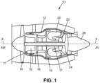
- a turbomachine 10 of the double-flow turbojet type comprises, from upstream to downstream in the direction of circulation of the gases inside the turbomachine 10, a fan 14, a low-pressure compressor 16, a high-pressure compressor 18, a combustion chamber 20, a high-pressure turbine 22, a low-pressure turbine 24 and an exhaust nozzle 26.
- the low-pressure compressor 16, the high-pressure compressor 18, the combustion chamber 20, the high-pressure turbine 22, the low-pressure turbine 24 and the exhaust nozzle 26 are arranged radially inside a casing 12 which delimits, radially outwards, an annular vein 11 of the turbomachine 10 in which the gases flow from upstream to downstream.
- the high-pressure compressor 18 and the low-pressure compressor 16 are respectively connected to a high-pressure turbine 22 and a low-pressure turbine 24 by a respective shaft 15, 17 extending along the longitudinal axis X of rotation of the shafts of the turbomachine 10.
- orientation qualifiers such as “longitudinal”, “radial” and “circumferential” are defined with reference to the longitudinal axis.
- upstream and downstream are defined with respect to the direction of circulation of the gases within the turbomachine.
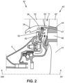
- the high-pressure turbine 22 comprises a plurality of stages, one of which is partially shown in FIG. Figure 2 , each comprising a distributor 30 and a mobile wheel 40 mounted downstream of the distributor 30.
- the distributor 30 comprises an internal annular platform 34 and an annular row of fixed blades 32. Each fixed blade 32 extends radially in the annular vein 11 and is connected, radially inside, to the internal annular platform 34.
- the distributor 30 generally comprises an annular radial flange 36 for attachment to the casing 5.
- the mobile wheel 40 comprises an annular row of mobile blades 42 carried by a disc 41 comprising a plurality of cells on its external periphery, each receiving a root 46 of a blade 42.
- Each mobile blade 42 further comprises a sector of a internal annular platform 44 of the mobile wheel 40 from which a blade 42' extends radially outwards through the annular vein 11.
- the internal annular platform 44 thus comprises a plurality of sectors arranged circumferentially end to end around the longitudinal axis X.
- the internal annular platform 34 of the distributor 30 and the internal annular platform 44 of the moving wheel 40 each delimit, radially inwards, the annular vein 11.
- the gases flowing in the annular vein 11 are introduced into a space formed longitudinally between the internal annular platform 34 of the distributor 30 and the internal annular platform 44 of the moving wheel 40, which reduces the performance of the turbomachine 10.
- a baffle is formed in the longitudinal space between the internal annular platform 34 of the distributor 30 and the internal annular platform 44 of the moving wheel 44, limiting the leakage, radially inwards, of the gases flowing in the annular vein 11.
- a purge air flow taken from the low-pressure compressor 16 and/or the high-pressure compressor 18, is directed through an annular purge cavity 62 towards the space formed longitudinally between the internal annular platform 34 of the distributor 30 and the internal annular platform 44 of the mobile wheel 4.
- This purge air flow thus makes it possible to redirect the gases that have entered the purge cavity 62 towards the annular vein 11.
- US 9,605,552 B2 generally discloses a downstream sealing part applied against an upstream face of a disc of an annular row of moving blades.
- the present invention improves the situation.
- the arrangement of the first downstream spoiler delimiting the first annular recirculation cavity allows the formation of a swirl, or vortex, of the gases in the annular vein which are introduced into the first annular recirculation cavity, these gases mixing with a purge air flow coming from the second annular recirculation cavity and from the annular purge cavity.
- a vortex makes it possible, on the one hand, to limit, or even prevent, the gases from the annular vein from flowing further radially inwards, and on the other hand, to redirect these gases towards the annular vein.
- the vortex prevents a radially inwards flow of gases coming from the annular vein.
- the gases coming from the annular vein entering the first annular recirculation cavity are thus advantageously mainly contained in the first annular recirculation cavity.
- the second annular recirculation cavity also allows the formation of a swirl, or vortex, of the gases from the first annular recirculation cavity which are introduced into the secondary annular recirculation cavity, these gases mixing with a flow of purge air coming from the annular purge cavity.
- a swirl makes it possible to limit, or even prevent, the gases from flowing further radially inwards, and on the other hand, to redirect these gases towards the first annular recirculation cavity.
- the swirl here prevents a flow, radially inwards, of the gases coming from the first annular recirculation cavity.
- the gases coming from the first annular recirculation cavity introduced into the second annular recirculation cavity are thus advantageously mainly contained in the secondary annular recirculation cavity.
- the bleed air flow rate required to redirect the gases that have entered the first and second annular recirculation cavities to the annular flow path is reduced.
- the elements of the annular row of moving blades are better protected.
- the amount of bleed air taken from the high-pressure compressor and/or the low-pressure compressor is reduced, which improves the efficiency of the turbomachine.
- the feature that the first downstream spoiler protrudes radially outwardly from the sealing part is, in other words, equivalent to the first downstream spoiler extending radially outwardly from an annular portion of the sealing part.
- the first downstream spoiler may extend from a radially outer end of the annular portion of the sealing part.
- the characteristic that the second downstream spoiler forms a projection downstream of the sealing part is equivalent, in other words, to the second spoiler downstream extends longitudinally downstream from an annular portion of the sealing part.
- the first downstream spoiler may extend radially outward from a radially outer end of an annular portion of the upstream sealing part, said first annular recirculation cavity being delimited, radially inward, by a radially outer face of the annular portion of the upstream sealing part, the radially outer annular face of said annular portion having, in whole or in part, a concave shape.
- the concave shape further promotes the formation of a vortex or whirlpool within the first recirculation cavity.
- the first downstream spoiler may extend radially outward from a radially outer end of an annular portion of the upstream sealing part, the first downstream spoiler comprising a downstream-flaring frustoconical wall extending from the radially outer and downstream end of the annular portion of the upstream sealing part and a radial wall extending radially outward from a downstream end of said frustoconical wall.
- the second downstream spoiler can be cylindrical, that is, can extend longitudinally downstream.
- the angle between the truncated wall of the first downstream spoiler and the second downstream spoiler is between 30 and 45°, preferably between 35 and 40°.
- Such an angle promotes the formation of vortices or whirlpools in each of the first and second recirculation cavities.
- Such a recess or detachment helps to promote the formation of a vortex or whirlpool in the second recirculation cavity, and prevents the introduction of hot gases into the purge cavity.
- the upstream spoiler may have a radially external face which is of truncated cone shape with a section decreasing towards the upstream extending over at least a first longitudinal portion.
- Such a shape makes it easier to evacuate purge air and gases from the first recirculation cavity to the annular vein. Furthermore, such a feature makes it possible to adapt the direction in which the gases mixed in the annular vein are reintroduced into the annular vein to minimize disturbances to the gases flowing in the annular vein.
- the distributor may further comprise a radial annular flange extending radially inwardly from the inner annular platform, the upstream sealing part being attached and fixed to the radial annular flange.
- the second downstream spoiler may have a radially outwardly projecting portion at its downstream end.
- a turbomachine comprising a high-pressure gas turbine of the aforementioned type.
- the high-pressure turbine comprises a plurality of stages each comprising a distributor 30 and a moving wheel 40 mounted downstream of the distributor 30.
- the distributor 30 comprises an annular row of fixed blades 32.
- Each fixed blade 32 is connected, radially inward, to an inner annular platform 34 of the distributor 30.
- Each fixed blade 32 extends radially outward from the inner annular platform 34.
- Each fixed blade 32 is connected, radially outward, to an outer platform 34' connected to an outer casing of the high-pressure turbine.
- a radially outer annular face of the inner annular platform 34 and a radially inner annular face of the outer platform 34' delimit, radially, respectively inwardly and outwardly, an annular vein 11 of the turbomachine 10 at the distributor 30 of the high-pressure turbine.
- each fixed blade 32 extends radially inside the annular vein 11.
- the distributor 30 further comprises a radial annular flange 36 extending radially inward from the internal annular platform 34.
- the distributor 30 can be connected to an internal turbomachine casing via the radial annular flange 36.
- the movable wheel 40 comprises an annular row of movable blades 42 carried by a disc 41.
- the movable wheel 40 comprises an internal annular platform 44.
- Each movable blade 42 of the movable wheel 40 comprises a sector of the internal annular platform 44, the sectors being arranged circumferentially end to end around the longitudinal axis X.
- a radially external annular face 44a of the internal annular platform 44 delimits, radially inwards, the annular vein 11 at the movable wheel 40 of the turbine.
- Each movable blade 42 comprises a blade 42' extending, radially outwards, into the annular vein 11 from the respective sector of the internal annular platform 44.
- the movable wheel 40 also comprises a downstream sealing part 43 attached and fixed to an upstream radial surface of the disc 41 and of the zone comprising the platform 44.
- the downstream sealing part 43 comprises an upstream annular spoiler 47 which is annular and which extends at the level of the radially external end of the downstream sealing part 43.
- the upstream annular spoiler 47 is arranged, here in part, radially inside the internal annular platform 34 of the distributor 30.
- the upstream annular spoiler 47 is arranged radially inside the internal annular platform 34 of the distributor 30 and, in part, radially opposite the internal annular platform 34 of the distributor 30.
- the upstream end of the upstream spoiler 47 is located longitudinally more upstream than the downstream end of the internal platform 34.
- the downstream sealing part 43 may be an integral part of the disc 41 and/or the platform 44.
- the high-pressure turbine further comprises an upstream sealing part 50, which is here annular, applied against a downstream face of the distributor 30.
- the upstream sealing part 50 is here attached and fixed to the radial annular flange 36.
- the upstream sealing part 50 comprises an annular part 52 applied against a downstream face of the radial annular flange 36 of the distributor 30.
- the annular part 52 of the upstream sealing part 50 can be fixed, for example by bolting, to the radial annular flange 36 of the distributor 30.
- the upstream sealing part can be an integral part of the casing of the high-pressure turbine.
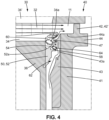
- the upstream sealing part 50 comprises a first downstream spoiler 54 which is annular.
- the first downstream annular spoiler 54 is arranged, here in part, radially inside the upstream annular spoiler 47 of the downstream sealing part 43.
- the first downstream annular spoiler 54 is arranged radially inside the upstream annular spoiler 47 and, in part, radially opposite the upstream annular spoiler 47.
- the first downstream annular spoiler 54 extends radially outward from a radially outer end of the annular portion 52 of the annular sealing part 50.
- a radially outer end 55 of the first downstream annular spoiler 54 is arranged radially opposite the upstream annular spoiler 47, thus forming a first annular recirculation cavity 60 which is delimited, longitudinally, by the distributor 30 and the first downstream spoiler 54.
- the first annular cavity recirculation cavity 60 is here delimited, radially outwards, by a radially internal face 34a of the internal annular platform 34 of the distributor 30.
- the first annular recirculation cavity 60 is delimited, radially inwards, by a radially external annular face 52a of the annular part 52 of the upstream annular sealing part 50.
- the first annular recirculation cavity 60 here forms a free space. In other words, the first annular recirculation cavity 60 is here devoid of any solid element.
- a free space is formed, longitudinally, between the internal annular platform 34 of the distributor 30 and the internal annular platform 44 of the movable wheel 40.
- the internal annular platform 34 of the distributor 30 and the upstream annular spoiler 47 of the movable wheel 40 together define a clearance or flow conduit between the annular vein 11 and the first annular recirculation cavity 60.
- Such an arrangement of the first downstream annular spoiler 54 delimiting the first annular recirculation cavity 60 allows the formation of a swirl, or vortex (illustrated by arrows to the Figure 4 ), gases flowing in the annular vein 11 which are introduced into the first annular recirculation cavity 60, these gases mixing with a flow of purge air coming from an annular purge cavity 62 and from a second annular recirculation cavity 64 located radially inwards between the distributor 30 and the movable wheel 40.
- a vortex makes it possible, on the one hand, to limit, or even prevent, the gases of the vein 11 from flowing further radially inwards, and on the other hand, to redirect these gases towards the annular vein 11.
- the vortex prevents a flow, radially inwards, of the gases coming from the annular vein 11.
- the gases coming from the annular vein 11 entering the first recirculation cavity 60 are thus advantageously contained in this cavity 60.
- the quantity of gas from the annular vein 11 which enters the second recirculation cavity 64 and the annular purge cavity 62 are thus advantageously contained in this cavity 60.
- the purge air flow rate required to redirect the gases that have entered the first annular recirculation cavity 60 to the annular flow path 11 is reduced.
- the mobile wheel elements 40 are better protected.
- the quantity of purge air taken from the high-pressure compressor and/or the low-pressure compressor is reduced, which makes it possible to improve the efficiency of the turbomachine.
- the first downstream annular spoiler 54 comprises a frustoconical wall 54a flared downstream and extending from the radially external and downstream end of the annular portion 52 of the annular sealing part 50.
- the thickness of the frustoconical wall 54a decreases slightly downstream.
- the first downstream annular spoiler 54 also comprises a radial annular wall 54b extending radially outward from a downstream end of the frustoconical wall 54a.
- a radial clearance is formed between the radially external end of the first downstream spoiler 54 and the upstream spoiler 47, allowing the passage of a purge air flow coming from the second recirculation cavity 64 and the purge cavity 62.
- the annular portion 52 of the annular sealing part 50 has a radially external annular face 52a having a concave shape.
- the first downstream annular spoiler 54 may also have a plurality of holes (not shown) which may be regularly distributed circumferentially around the longitudinal axis X.
- the plurality of holes may extend through the frustoconical wall 54a of the first downstream annular spoiler 54. This allows a purge air flow to pass through the holes 56 towards the first annular recirculation cavity 60, in particular at the level where the gas pressure in the first annular recirculation cavity 60 is the highest. This further limits the introduction of gases coming from the vein annular 11 in the second recirculation cavity 64 and in the annular purge cavity 62.
- the first upstream annular spoiler 47 has a radially external annular face 47a which is of truncated cone shape with a section decreasing towards the upstream and which extends over a first longitudinal portion of the first upstream annular spoiler 47.
- the first portion of the upstream annular spoiler 47 is, here in part, radially opposite the internal annular platform 34 of the distributor 30.
- the radially external annular face 47a of the first portion of the upstream annular spoiler 47 is here connected to the radially external annular face 44a of the internal annular platform 44 of the moving wheel 40, in particular by a rounding.
- the gases from the annular flow path 11 introduced into the first annular recirculation cavity 60 via the conduit or clearance formed between said upstream annular spoiler 47 and the internal annular platform 34 of the distributor 30 are mixed with the purge air flow to be redirected to the annular flow path 11.
- a radially external annular face 47a of the upstream annular spoiler 47 makes it possible to adapt the direction in which the gases mixed in the annular flow path 11 are reintroduced into the annular flow path 11 to minimize disturbances on the gases flowing in the annular flow path 11.
- the conicity of the radially external annular face 47a of the upstream annular spoiler 47 may be chosen to minimize disturbances on the gases flowing in the annular flow path 11.
- the radially internal annular face 34a of the internal annular platform 34 of the distributor 30 has, here in part, a concave shape which is arranged radially opposite the upstream annular spoiler 47.
- a concave shape of the radially internal annular face 34a of the internal annular platform 34 of the distributor 30 makes it possible to promote the appearance of a vortex at the interface between the gases coming from the annular vein 11 and the purge air.
- the upstream sealing part 50 comprises a second downstream annular spoiler 58 arranged radially inside the first downstream annular spoiler 54.
- the second downstream annular spoiler 58 extends longitudinally downstream from the annular portion 52 of the annular sealing part 50.
- the second downstream spoiler 58 has a cylindrical shape and forms an angle of between 30 and 45°, preferably between 35 and 40°, with the frustoconical wall 54a of the first downstream spoiler 54.
- the second downstream spoiler 58 is located axially opposite an annular recess 43a formed in the downstream sealing part 43. An axial clearance is formed between the downstream end of the second downstream spoiler 58 and the wall bottom of the recess 43a, so as to allow the passage of a purge air flow coming from the purge cavity 62.
- the second recirculation cavity 64 is delimited by the first downstream spoiler 54, the second downstream spoiler 58 and the upstream surface of the second sealing part 43.
- a small quantity of gases from the first annular recirculation cavity 60 can flow into the second recirculation cavity 64 through the clearance formed between the upstream spoiler 47 and the first downstream spoiler 54. These gases are then mixed with the purge air flow from the purge cavity 62, entering the second recirculation cavity 64 through the clearance formed between the second downstream spoiler 58 and the downstream sealing part 43. Once mixed with the air, these gases are redirected towards the first recirculation cavity 60 then towards the annular vein 11.
- the shape of the second cavity 64 makes it possible to generate vortices or whirlpools, illustrated by arrows at the Figure 4 , making it possible to facilitate such mixing and such evacuation. This limits, or even prevents, a flow of gases towards the purge cavity 62.
- FIG. 6 illustrates an alternative embodiment in which a portion of the second downstream spoiler 58, for example the downstream end of the second downstream spoiler, comprises a projecting portion 58a radially outwardly, for example an oblique portion radially outwardly and longitudinally downstream.
- a projecting portion 58a makes it possible to further improve the evacuation efficiency of the vortex created at the level of the second recirculation cavity 64.
- the annular sealing part 50 may be made in one piece with the radial annular flange 36 of the distributor 30.
- the annular sealing part 50 may comprise a plurality of sectors arranged circumferentially end to end around the longitudinal axis X.
Landscapes
- Engineering & Computer Science (AREA)
- Mechanical Engineering (AREA)
- General Engineering & Computer Science (AREA)
- Turbine Rotor Nozzle Sealing (AREA)
Claims (10)
- Hochdruck-Gasturbine für ein Turbotriebwerk (10), das sich um eine Längsachse (X) erstreckt, wobei die Turbine umfasst:- einen Leitapparat (30) mit einer inneren ringförmigen Plattform (34) und einer ringförmigen Aneinanderreihung von Leitschaufeln (32), wobei jede Leitschaufel (32) radial nach innen mit der inneren ringförmigen Plattform (34) verbunden ist,- eine ringförmige Aneinanderreihung von Laufschaufeln (40), die stromabwärts des Leitapparats (30) gelagert ist und eine Scheibe (41) umfasst, von der aus sich Schaufeln (42) radial nach außen erstrecken,- ein stromaufwärtiges Dichtungsteil (50), das an einer stromabwärtigen Fläche des Leitapparats (30) anliegt, und ein stromabwärtiges Dichtungsteil (43), das an einer stromaufwärtigen Fläche der Scheibe (41) der ringförmigen Aneinanderreihung von Laufschaufeln (40) anliegt,wobei das stromabwärtige Dichtungsteil (43) einen stromaufwärtigen Vorsprung (47) umfasst, der zumindest teilweise radial innerhalb der inneren ringförmigen Plattform (34) des Leitapparats (30) angeordnet ist, wobei das stromaufwärtige Dichtungsteil (50) einen ersten stromabwärtigen Vorsprung (54) umfasst, der ganz oder teilweise radial innerhalb des stromaufwärtigen Vorsprungs (47) des stromaufwärtigen Dichtungsteils (50) angeordnet ist,wobei der erste stromabwärtige Vorsprung (54) eine Auskragung radial nach außen von dem Dichtungsteil (50) bildet, wobei ein radial äußeres Ende (55) des ersten stromabwärtigen Vorsprungs (54) radial gegenüber dem stromaufwärtigen Vorsprung (47) angeordnet ist, wodurch ein erster ringförmiger Rezirkulationshohlraum (60) gebildet ist, der in Längsrichtung von dem Leitapparat (30) und dem ersten stromabwärtigen Vorsprung (54) begrenzt ist,wobei das stromaufwärtige Dichtungsteil (50) einen zweiten stromabwärtigen Vorsprung (58) umfasst, der eine Auskragung in Richtung stromabwärts bildet, wobei der zweite stromabwärtige Vorsprung (58) radial innerhalb des ersten stromabwärtigen Vorsprungs (54) angeordnet ist, wobei das stromabwärtige Dichtungsteil (43) eine sich radial erstreckende stromaufwärtige Fläche aufweist, die keinen Vorsprung radial zwischen dem ersten stromabwärtigen Vorsprung (54) und dem zweiten stromabwärtigen Vorsprung (58) des stromaufwärtigen Dichtungsteils (50) umfasst, wodurch ein zweiter ringförmiger Rezirkulationshohlraum (60) gebildet ist, der von dem ersten stromabwärtigen Vorsprung (54) und dem zweiten stromabwärtigen Vorsprung (58) des stromaufwärtigen Dichtungsteils (50) und von der stromaufwärtigen Fläche des stromabwärtigen Dichtungsteils (43) begrenzt ist,wobei ein ringförmiger Ablasshohlraum (62) zwischen dem Leitapparat (30) und der ringförmigen Aneinanderreihung von Laufschaufeln (40) begrenzt ist und sich radial innerhalb des zweiten ringförmigen Rezirkulationshohlraums (64) befindet,wobei ein Ablassluftstrom oder ein Gasstrom zwischen einem ringförmigen Strömungskanal (11), der sich radial außerhalb der inneren Plattform (34) des Leitapparats (30) befindet, und dem ersten ringförmigen Zirkulationshohlraum (60) durch einen Spalt zwischen der inneren Plattform (34) und dem stromaufwärtigen Vorsprung (47), zwischen dem ersten Rezirkulationshohlraum (60) und dem zweiten Zirkulationshohlraum (64) durch einen Spalt zwischen dem ersten stromabwärtigen Vorsprung (54) unddem stromaufwärtigen Vorsprung (47), und zwischen dem zweiten Rezirkulationshohlraum (64) und dem Ablasshohlraum (62) durch einen Spalt zwischen dem zweiten stromabwärtigen Vorsprung (58) und dem stromabwärtigen Dichtungsteil (43) strömen kann.
- Turbine nach Anspruch 1, wobei sich der erste stromabwärtige Vorsprung (54) von einem radial äußeren Ende eines ringförmigen Abschnitts (52) des Dichtungsteils (50) radial nach außen erstreckt, wobei der erste ringförmige Rezirkulationshohlraum (60) von einer radial äußeren Fläche (52a) des ringförmigen Abschnitts (52) des Dichtungsteils (50) radial nach innen begrenzt ist, wobei die radial äußere ringförmige Fläche (52a) des ringförmigen Abschnitts (52) ganz oder teilweise eine konkave Form aufweist.
- Turbine nach einem der vorhergehenden Ansprüche, wobei sich der erste stromabwärtige Vorsprung (54) von einem radial äußeren Ende eines ringförmigen Abschnitts (52) des stromabwärtigen Dichtungsteils (43) (50) radial nach außen erstreckt, wobei der erste stromabwärtige Vorsprung (54) eine sich stromabwärts erweiternde kegelstumpfförmige Wand (54a) aufweist, die sich ausgehend von dem radial äußeren, stromabwärtigen Ende des ringförmigen Abschnitts (52) des stromaufwärtigen Dichtungsteils (50) erstreckt, sowie eine radiale Wand (54b), die sich ausgehend von einem stromabwärtigen Ende der kegelstumpfförmigen Wand (54a) radial nach außen erstreckt.
- Turbine nach einem der vorhergehenden Ansprüche, wobei der zweite stromabwärtige Vorsprung (58) zylindrisch ausgebildet ist.
- Turbine nach Anspruch 3 und 4, wobei der Winkel zwischen der kegelstumpfförmigen Wand (54a) des ersten stromabwärtigen Vorsprungs (54) und dem zweiten stromabwärtigen Vorsprung (58) zwischen 30 und 45°, vorzugsweise zwischen 35 und 40°, beträgt.
- Turbine nach einem der vorhergehenden Ansprüche, wobei der zweite stromabwärtige Vorsprung (58) axial gegenüber einer Vertiefung (43a) oder einem Absatz angeordnet ist, die bzw. der in dem stromabwärtigen Dichtungsteil (43) ausgebildet ist.
- Turbine nach einem der vorhergehenden Ansprüche, wobei der stromaufwärtige Vorsprung (47) eine radial äußere Fläche (47a) aufweist, die kegelstumpfförmig mit einem sich stromaufwärts verjüngenden Querschnitt ausgebildet ist und sich über zumindest einen ersten Längsabschnitt erstreckt.
- Turbine nach einem der vorhergehenden Ansprüche, wobei der Leitapparat (30) ferner einen radialen Ringflansch (36) aufweist, der sich ausgehend von der inneren ringförmigen Plattform (34) radial nach innen erstreckt, wobei das stromaufwärtige Dichtungsteil (50) an den radialen Ringflansch (36) angesetzt und daran befestigt ist.
- Turbine nach einem der vorhergehenden Ansprüche, wobei der zweite stromabwärtige Vorsprung (58) an seinem stromabwärtigen Ende einen radial nach außen vorstehenden Abschnitt (58a) aufweist.
- Turbotriebwerk mit einer Hochdruck-Gasturbine nach einem der vorhergehenden Ansprüche.
Applications Claiming Priority (2)
| Application Number | Priority Date | Filing Date | Title |
|---|---|---|---|
| FR2110133A FR3127520B1 (fr) | 2021-09-27 | 2021-09-27 | Turbine a gaz haute-pression pour turbomachine |
| PCT/FR2022/051663 WO2023047034A1 (fr) | 2021-09-27 | 2022-09-02 | Turbine à gaz haute-pression pour une turbomachine et turbomachine |
Publications (2)
| Publication Number | Publication Date |
|---|---|
| EP4409114A1 EP4409114A1 (de) | 2024-08-07 |
| EP4409114B1 true EP4409114B1 (de) | 2025-06-11 |
Family
ID=80122503
Family Applications (1)
| Application Number | Title | Priority Date | Filing Date |
|---|---|---|---|
| EP22786385.9A Active EP4409114B1 (de) | 2021-09-27 | 2022-09-02 | Hochdruck-gasturbine für eine turbomaschine und turbomaschine |
Country Status (5)
| Country | Link |
|---|---|
| US (1) | US12345161B2 (de) |
| EP (1) | EP4409114B1 (de) |
| CN (1) | CN117980585A (de) |
| FR (1) | FR3127520B1 (de) |
| WO (1) | WO2023047034A1 (de) |
Families Citing this family (2)
| Publication number | Priority date | Publication date | Assignee | Title |
|---|---|---|---|---|
| FR3127519B1 (fr) * | 2021-09-27 | 2023-09-22 | Safran Aircraft Engines | Turbine a gaz haute-pression pour turbomachine |
| CN118979794A (zh) * | 2024-08-14 | 2024-11-19 | 中国航发湖南动力机械研究所 | 一种轮缘封严结构、涡轮结构及航空发动机 |
Family Cites Families (6)
| Publication number | Priority date | Publication date | Assignee | Title |
|---|---|---|---|---|
| US20060275107A1 (en) * | 2005-06-07 | 2006-12-07 | Ioannis Alvanos | Combined blade attachment and disk lug fluid seal |
| US8696320B2 (en) * | 2009-03-12 | 2014-04-15 | General Electric Company | Gas turbine having seal assembly with coverplate and seal |
| FR2982635B1 (fr) * | 2011-11-15 | 2013-11-15 | Snecma | Roue a aubes pour une turbomachine |
| EP2759675A1 (de) * | 2013-01-28 | 2014-07-30 | Siemens Aktiengesellschaft | Turbinenbaugruppe mit verbesserter Abdichtwirkung einer Dichtungsanordnung |
| US9605552B2 (en) * | 2013-06-10 | 2017-03-28 | General Electric Company | Non-integral segmented angel-wing seal |
| US11459903B1 (en) * | 2021-06-10 | 2022-10-04 | Solar Turbines Incorporated | Redirecting stator flow discourager |
-
2021
- 2021-09-27 FR FR2110133A patent/FR3127520B1/fr active Active
-
2022
- 2022-09-02 WO PCT/FR2022/051663 patent/WO2023047034A1/fr not_active Ceased
- 2022-09-02 CN CN202280062230.3A patent/CN117980585A/zh active Pending
- 2022-09-02 EP EP22786385.9A patent/EP4409114B1/de active Active
- 2022-09-02 US US18/694,563 patent/US12345161B2/en active Active
Also Published As
| Publication number | Publication date |
|---|---|
| WO2023047034A1 (fr) | 2023-03-30 |
| EP4409114A1 (de) | 2024-08-07 |
| US20240392692A1 (en) | 2024-11-28 |
| FR3127520A1 (fr) | 2023-03-31 |
| US12345161B2 (en) | 2025-07-01 |
| CN117980585A (zh) | 2024-05-03 |
| FR3127520B1 (fr) | 2023-08-18 |
Similar Documents
| Publication | Publication Date | Title |
|---|---|---|
| EP4025780B1 (de) | Ausstosskonus mit flexibler aerodynamischer befestigung | |
| EP3781791B1 (de) | Turbinenleitschaufel umfassend ein passives system zum wiedereinleiten von leckgas in den gaspfad | |
| EP4409114B1 (de) | Hochdruck-gasturbine für eine turbomaschine und turbomaschine | |
| CA2858797C (fr) | Redresseur de compresseur pour turbomachine | |
| FR3119199A1 (fr) | Conduit de decharge a etancheite perfectionnee | |
| EP3721058B1 (de) | Verbindung zwischen einem leitkranzsektor aus verbundwerkstoff mit keramischer matrix und einem metallischen träger einer turbine einer turbomaschine | |
| EP3969813A1 (de) | Brennkammer mit mitteln zur kühlung einer ringförmigen mantelzone hinter einem kamin | |
| EP4409113B1 (de) | Hochdruck-gasturbine für eine turbomaschine und turbomaschine | |
| FR3118782A1 (fr) | Turbine a gaz haute-pression pour turbomachine | |
| FR3118783A1 (fr) | Turbine a gaz haute-pression pour turbomachine | |
| EP4143421A1 (de) | Gehäuse mit zwischenflussglättung mit monoblockstrukturarm | |
| FR3116305A1 (fr) | Arbre de liaison d’un corps haute pression d’une turbomachine | |
| FR3147834A1 (fr) | Ensemble rotorique de turbine pour turbomachine | |
| EP3983661B1 (de) | Vorrichtung zur kühlung des gehäuses einer turbomaschine | |
| FR3092865A1 (fr) | Disque de rotor avec arret axial des aubes, ensemble d’un disque et d’un anneau et turbomachine | |
| FR3129987A1 (fr) | Tuyere d’echappement de gaz de combustion pour une turbomachine d’aeronef | |
| EP3568638B1 (de) | Brennkammer für einen turbinenmotor | |
| FR3127518A1 (fr) | Étage de turbomachine comprenant au moins un anneau d’étanchéité | |
| WO2026052916A1 (fr) | Module pour une turbomachine d'aeronef | |
| FR3129988A1 (fr) | Tuyere d’echappement de gaz de combustion pour une turbomachine d’aeronef | |
| WO2026052915A1 (fr) | Module pour une turbomachine d'aeronef | |
| WO2026052918A1 (fr) | Module pour une turbomachine d'aeronef | |
| FR3127785A1 (fr) | Ensemble pour turbine pour turbomachine d’aeronef | |
| FR3156489A1 (fr) | Turbomachine pour un aeronef | |
| FR3039225A1 (fr) | Turbomachine, telle par exemple qu'un turboreacteur d'avion |
Legal Events
| Date | Code | Title | Description |
|---|---|---|---|
| STAA | Information on the status of an ep patent application or granted ep patent |
Free format text: STATUS: UNKNOWN |
|
| STAA | Information on the status of an ep patent application or granted ep patent |
Free format text: STATUS: THE INTERNATIONAL PUBLICATION HAS BEEN MADE |
|
| PUAI | Public reference made under article 153(3) epc to a published international application that has entered the european phase |
Free format text: ORIGINAL CODE: 0009012 |
|
| STAA | Information on the status of an ep patent application or granted ep patent |
Free format text: STATUS: REQUEST FOR EXAMINATION WAS MADE |
|
| 17P | Request for examination filed |
Effective date: 20240408 |
|
| AK | Designated contracting states |
Kind code of ref document: A1 Designated state(s): AL AT BE BG CH CY CZ DE DK EE ES FI FR GB GR HR HU IE IS IT LI LT LU LV MC MK MT NL NO PL PT RO RS SE SI SK SM TR |
|
| DAV | Request for validation of the european patent (deleted) | ||
| DAX | Request for extension of the european patent (deleted) | ||
| GRAP | Despatch of communication of intention to grant a patent |
Free format text: ORIGINAL CODE: EPIDOSNIGR1 |
|
| STAA | Information on the status of an ep patent application or granted ep patent |
Free format text: STATUS: GRANT OF PATENT IS INTENDED |
|
| INTG | Intention to grant announced |
Effective date: 20250214 |
|
| GRAS | Grant fee paid |
Free format text: ORIGINAL CODE: EPIDOSNIGR3 |
|
| GRAA | (expected) grant |
Free format text: ORIGINAL CODE: 0009210 |
|
| STAA | Information on the status of an ep patent application or granted ep patent |
Free format text: STATUS: THE PATENT HAS BEEN GRANTED |
|
| AK | Designated contracting states |
Kind code of ref document: B1 Designated state(s): AL AT BE BG CH CY CZ DE DK EE ES FI FR GB GR HR HU IE IS IT LI LT LU LV MC MK MT NL NO PL PT RO RS SE SI SK SM TR |
|
| REG | Reference to a national code |
Ref country code: GB Ref legal event code: FG4D Free format text: NOT ENGLISH |
|
| REG | Reference to a national code |
Ref country code: CH Ref legal event code: EP |
|
| REG | Reference to a national code |
Ref country code: DE Ref legal event code: R096 Ref document number: 602022015897 Country of ref document: DE |
|
| REG | Reference to a national code |
Ref country code: IE Ref legal event code: FG4D Free format text: LANGUAGE OF EP DOCUMENT: FRENCH |
|
| PG25 | Lapsed in a contracting state [announced via postgrant information from national office to epo] |
Ref country code: FI Free format text: LAPSE BECAUSE OF FAILURE TO SUBMIT A TRANSLATION OF THE DESCRIPTION OR TO PAY THE FEE WITHIN THE PRESCRIBED TIME-LIMIT Effective date: 20250611 Ref country code: ES Free format text: LAPSE BECAUSE OF FAILURE TO SUBMIT A TRANSLATION OF THE DESCRIPTION OR TO PAY THE FEE WITHIN THE PRESCRIBED TIME-LIMIT Effective date: 20250611 |
|
| PGFP | Annual fee paid to national office [announced via postgrant information from national office to epo] |
Ref country code: DE Payment date: 20250919 Year of fee payment: 4 |
|
| REG | Reference to a national code |
Ref country code: LT Ref legal event code: MG9D |
|
| PG25 | Lapsed in a contracting state [announced via postgrant information from national office to epo] |
Ref country code: GR Free format text: LAPSE BECAUSE OF FAILURE TO SUBMIT A TRANSLATION OF THE DESCRIPTION OR TO PAY THE FEE WITHIN THE PRESCRIBED TIME-LIMIT Effective date: 20250912 Ref country code: NO Free format text: LAPSE BECAUSE OF FAILURE TO SUBMIT A TRANSLATION OF THE DESCRIPTION OR TO PAY THE FEE WITHIN THE PRESCRIBED TIME-LIMIT Effective date: 20250911 |
|
| REG | Reference to a national code |
Ref country code: NL Ref legal event code: MP Effective date: 20250611 |
|
| PG25 | Lapsed in a contracting state [announced via postgrant information from national office to epo] |
Ref country code: BG Free format text: LAPSE BECAUSE OF FAILURE TO SUBMIT A TRANSLATION OF THE DESCRIPTION OR TO PAY THE FEE WITHIN THE PRESCRIBED TIME-LIMIT Effective date: 20250611 |
|
| PG25 | Lapsed in a contracting state [announced via postgrant information from national office to epo] |
Ref country code: HR Free format text: LAPSE BECAUSE OF FAILURE TO SUBMIT A TRANSLATION OF THE DESCRIPTION OR TO PAY THE FEE WITHIN THE PRESCRIBED TIME-LIMIT Effective date: 20250611 |
|
| PGFP | Annual fee paid to national office [announced via postgrant information from national office to epo] |
Ref country code: FR Payment date: 20250923 Year of fee payment: 4 Ref country code: AT Payment date: 20251020 Year of fee payment: 4 |
|
| PG25 | Lapsed in a contracting state [announced via postgrant information from national office to epo] |
Ref country code: RS Free format text: LAPSE BECAUSE OF FAILURE TO SUBMIT A TRANSLATION OF THE DESCRIPTION OR TO PAY THE FEE WITHIN THE PRESCRIBED TIME-LIMIT Effective date: 20250911 |
|
| PG25 | Lapsed in a contracting state [announced via postgrant information from national office to epo] |
Ref country code: LV Free format text: LAPSE BECAUSE OF FAILURE TO SUBMIT A TRANSLATION OF THE DESCRIPTION OR TO PAY THE FEE WITHIN THE PRESCRIBED TIME-LIMIT Effective date: 20250611 |
|
| PG25 | Lapsed in a contracting state [announced via postgrant information from national office to epo] |
Ref country code: NL Free format text: LAPSE BECAUSE OF FAILURE TO SUBMIT A TRANSLATION OF THE DESCRIPTION OR TO PAY THE FEE WITHIN THE PRESCRIBED TIME-LIMIT Effective date: 20250611 |
|
| PG25 | Lapsed in a contracting state [announced via postgrant information from national office to epo] |
Ref country code: PT Free format text: LAPSE BECAUSE OF FAILURE TO SUBMIT A TRANSLATION OF THE DESCRIPTION OR TO PAY THE FEE WITHIN THE PRESCRIBED TIME-LIMIT Effective date: 20251013 |
|
| REG | Reference to a national code |
Ref country code: AT Ref legal event code: MK05 Ref document number: 1802417 Country of ref document: AT Kind code of ref document: T Effective date: 20250611 |
|
| PG25 | Lapsed in a contracting state [announced via postgrant information from national office to epo] |
Ref country code: IS Free format text: LAPSE BECAUSE OF FAILURE TO SUBMIT A TRANSLATION OF THE DESCRIPTION OR TO PAY THE FEE WITHIN THE PRESCRIBED TIME-LIMIT Effective date: 20251011 |
|
| PG25 | Lapsed in a contracting state [announced via postgrant information from national office to epo] |
Ref country code: AT Free format text: LAPSE BECAUSE OF FAILURE TO SUBMIT A TRANSLATION OF THE DESCRIPTION OR TO PAY THE FEE WITHIN THE PRESCRIBED TIME-LIMIT Effective date: 20250611 Ref country code: SM Free format text: LAPSE BECAUSE OF FAILURE TO SUBMIT A TRANSLATION OF THE DESCRIPTION OR TO PAY THE FEE WITHIN THE PRESCRIBED TIME-LIMIT Effective date: 20250611 |
|
| PG25 | Lapsed in a contracting state [announced via postgrant information from national office to epo] |
Ref country code: CZ Free format text: LAPSE BECAUSE OF FAILURE TO SUBMIT A TRANSLATION OF THE DESCRIPTION OR TO PAY THE FEE WITHIN THE PRESCRIBED TIME-LIMIT Effective date: 20250611 |
|
| PG25 | Lapsed in a contracting state [announced via postgrant information from national office to epo] |
Ref country code: PL Free format text: LAPSE BECAUSE OF FAILURE TO SUBMIT A TRANSLATION OF THE DESCRIPTION OR TO PAY THE FEE WITHIN THE PRESCRIBED TIME-LIMIT Effective date: 20250611 |
|
| PG25 | Lapsed in a contracting state [announced via postgrant information from national office to epo] |
Ref country code: EE Free format text: LAPSE BECAUSE OF FAILURE TO SUBMIT A TRANSLATION OF THE DESCRIPTION OR TO PAY THE FEE WITHIN THE PRESCRIBED TIME-LIMIT Effective date: 20250611 |
|
| PG25 | Lapsed in a contracting state [announced via postgrant information from national office to epo] |
Ref country code: SK Free format text: LAPSE BECAUSE OF FAILURE TO SUBMIT A TRANSLATION OF THE DESCRIPTION OR TO PAY THE FEE WITHIN THE PRESCRIBED TIME-LIMIT Effective date: 20250611 |
|
| PG25 | Lapsed in a contracting state [announced via postgrant information from national office to epo] |
Ref country code: RO Free format text: LAPSE BECAUSE OF FAILURE TO SUBMIT A TRANSLATION OF THE DESCRIPTION OR TO PAY THE FEE WITHIN THE PRESCRIBED TIME-LIMIT Effective date: 20250611 |
|
| PG25 | Lapsed in a contracting state [announced via postgrant information from national office to epo] |
Ref country code: DK Free format text: LAPSE BECAUSE OF FAILURE TO SUBMIT A TRANSLATION OF THE DESCRIPTION OR TO PAY THE FEE WITHIN THE PRESCRIBED TIME-LIMIT Effective date: 20250611 |
|
| PG25 | Lapsed in a contracting state [announced via postgrant information from national office to epo] |
Ref country code: IT Free format text: LAPSE BECAUSE OF FAILURE TO SUBMIT A TRANSLATION OF THE DESCRIPTION OR TO PAY THE FEE WITHIN THE PRESCRIBED TIME-LIMIT Effective date: 20250611 |
|
| PLBE | No opposition filed within time limit |
Free format text: ORIGINAL CODE: 0009261 |
|
| STAA | Information on the status of an ep patent application or granted ep patent |
Free format text: STATUS: NO OPPOSITION FILED WITHIN TIME LIMIT |
|
| REG | Reference to a national code |
Ref country code: CH Ref legal event code: L10 Free format text: ST27 STATUS EVENT CODE: U-0-0-L10-L00 (AS PROVIDED BY THE NATIONAL OFFICE) Effective date: 20260423 |