EP4408596B1 - Système d'alimentation - Google Patents
Système d'alimentation Download PDFInfo
- Publication number
- EP4408596B1 EP4408596B1 EP22809682.2A EP22809682A EP4408596B1 EP 4408596 B1 EP4408596 B1 EP 4408596B1 EP 22809682 A EP22809682 A EP 22809682A EP 4408596 B1 EP4408596 B1 EP 4408596B1
- Authority
- EP
- European Patent Office
- Prior art keywords
- straightening
- measurement
- roller
- workpiece
- rod
- Prior art date
- Legal status (The legal status is an assumption and is not a legal conclusion. Google has not performed a legal analysis and makes no representation as to the accuracy of the status listed.)
- Active
Links
Images


Classifications
-
- B—PERFORMING OPERATIONS; TRANSPORTING
- B21—MECHANICAL METAL-WORKING WITHOUT ESSENTIALLY REMOVING MATERIAL; PUNCHING METAL
- B21C—MANUFACTURE OF METAL SHEETS, WIRE, RODS, TUBES, PROFILES OR LIKE SEMI-MANUFACTURED PRODUCTS OTHERWISE THAN BY ROLLING; AUXILIARY OPERATIONS USED IN CONNECTION WITH METAL-WORKING WITHOUT ESSENTIALLY REMOVING MATERIAL
- B21C47/00—Winding-up, coiling or winding-off metal wire, metal band or other flexible metal material characterised by features relevant to metal processing only
- B21C47/16—Unwinding or uncoiling
- B21C47/18—Unwinding or uncoiling from reels or drums
-
- B—PERFORMING OPERATIONS; TRANSPORTING
- B21—MECHANICAL METAL-WORKING WITHOUT ESSENTIALLY REMOVING MATERIAL; PUNCHING METAL
- B21C—MANUFACTURE OF METAL SHEETS, WIRE, RODS, TUBES, PROFILES OR LIKE SEMI-MANUFACTURED PRODUCTS OTHERWISE THAN BY ROLLING; AUXILIARY OPERATIONS USED IN CONNECTION WITH METAL-WORKING WITHOUT ESSENTIALLY REMOVING MATERIAL
- B21C51/00—Measuring, gauging, indicating, counting, or marking devices specially adapted for use in the production or manipulation of material in accordance with subclasses B21B - B21F
-
- B—PERFORMING OPERATIONS; TRANSPORTING
- B21—MECHANICAL METAL-WORKING WITHOUT ESSENTIALLY REMOVING MATERIAL; PUNCHING METAL
- B21D—WORKING OR PROCESSING OF SHEET METAL OR METAL TUBES, RODS OR PROFILES WITHOUT ESSENTIALLY REMOVING MATERIAL; PUNCHING METAL
- B21D3/00—Straightening or restoring form of metal rods, metal tubes, metal profiles, or specific articles made therefrom, whether or not in combination with sheet metal parts
- B21D3/02—Straightening or restoring form of metal rods, metal tubes, metal profiles, or specific articles made therefrom, whether or not in combination with sheet metal parts by rollers
- B21D3/05—Straightening or restoring form of metal rods, metal tubes, metal profiles, or specific articles made therefrom, whether or not in combination with sheet metal parts by rollers arranged on axes rectangular to the path of the work
-
- B—PERFORMING OPERATIONS; TRANSPORTING
- B21—MECHANICAL METAL-WORKING WITHOUT ESSENTIALLY REMOVING MATERIAL; PUNCHING METAL
- B21D—WORKING OR PROCESSING OF SHEET METAL OR METAL TUBES, RODS OR PROFILES WITHOUT ESSENTIALLY REMOVING MATERIAL; PUNCHING METAL
- B21D43/00—Feeding, positioning or storing devices combined with, or arranged in, or specially adapted for use in connection with, apparatus for working or processing sheet metal, metal tubes or metal profiles; Associations therewith of cutting devices
- B21D43/006—Feeding elongated articles, such as tubes, bars, or profiles
-
- B—PERFORMING OPERATIONS; TRANSPORTING
- B21—MECHANICAL METAL-WORKING WITHOUT ESSENTIALLY REMOVING MATERIAL; PUNCHING METAL
- B21F—WORKING OR PROCESSING OF METAL WIRE
- B21F1/00—Bending wire other than coiling; Straightening wire
- B21F1/02—Straightening
-
- B—PERFORMING OPERATIONS; TRANSPORTING
- B21—MECHANICAL METAL-WORKING WITHOUT ESSENTIALLY REMOVING MATERIAL; PUNCHING METAL
- B21F—WORKING OR PROCESSING OF METAL WIRE
- B21F1/00—Bending wire other than coiling; Straightening wire
- B21F1/02—Straightening
- B21F1/026—Straightening and cutting
-
- B—PERFORMING OPERATIONS; TRANSPORTING
- B21—MECHANICAL METAL-WORKING WITHOUT ESSENTIALLY REMOVING MATERIAL; PUNCHING METAL
- B21F—WORKING OR PROCESSING OF METAL WIRE
- B21F23/00—Feeding wire in wire-working machines or apparatus
Definitions
- the invention relates to a feeding system according to the preamble of claim 1.
- a feeding system of the type considered here has a feeding device which is designed to feed an elongated wire-shaped or tubular workpiece to a forming machine.
- the feeding device has a receiving device for receiving a workpiece supply in the form of a coil.
- the feeding device also has a straightening system downstream of the receiving device with two adjustable roller straightening devices connected in series with differently oriented straightening planes for straightening the workpiece before it enters the forming machine.
- the feeding system also includes a measuring unit for measuring residual curvatures on straightened wire-shaped or tubular straightening material which has passed through the straightening system of the feeding device and for determining measurement data which represent a residual curvature of the straightened straightening material.
- the roller straightening devices of the straightening system can be adjusted on the basis of the measurement data so that the straightening material has the desired straightening quality.
- Straightening is a manufacturing process from the group of forming processes and is used to make the elongated material, which is also referred to here as the straightened material, into a shape that is as straight as possible before further processing, i.e. into a state with little or no residual curvature.
- the material is fed from a material supply through a straightening system and the straightening system produces straightened material or straightened straightened material from the material by forming in a straightening operation.
- a roller straightener comprises a plurality of passive, i.e. non-rotationally driven straightening rollers with mutually parallel axes of rotation, which are arranged alternately on opposite sides of a through-passage path in a through-passage direction and define a straightening geometry when operating with peripheral sections in contact with the workpiece.
- a roller straightener With the help of a roller straightener, it is possible to convert one-dimensional initial curvatures (curvatures before entering the roller straightener) of a material to be straightened into a plane so that after the straightening process there is a defined residual curvature in this plane.
- the aim is to achieve an end product without residual curvature, i.e. a straight end product.
- straightening systems with two roller straighteners connected in series are used, which eliminate the initial curvatures in two mutually perpendicular planes.
- Straightening systems with roller straighteners do not rotate and therefore differ fundamentally from rotating straightening systems with so-called straightening wings, which apply straightening forces in many different planes.
- At least one of the straightening rollers can be adjusted in a feed direction oriented transversely to the direction of travel. This allows the straightening geometry of the roller straightener to be changed in order to achieve a better straightening result.
- a straightening roller can be adjusted manually, semi-automatically or automatically using an associated actuator (e.g. servo motor, pneumatic cylinder, hydraulic cylinder, etc.) in response to control signals from a control unit.
- Inadequate straightening results can occur, for example, when using fresh straightening material after changing the coil or switching to another process.
- Material inhomogeneities, changes in material properties and/or wear on straightening rollers can also lead to a deterioration in straightening results during the ongoing process.
- Raw material is also subject to manufacturing tolerances. Changes can be detected by regular checks using random samples. If there is an unacceptable deterioration in straightening quality, the straightening system should be better adjusted by changing the straightening geometry.
- the patent specification DE 195 03 850 C1 describes a non-rotating straightening device for bending machines with an integrated measuring device.
- the straightening device comprises at least one non-rotating straightening device for wire or strip material, which operates in at least one straightening plane.
- the straightening device has several consecutive straightening rollers which process the material and which can be adjusted in the straightening plane and transversely to the axis of passage of the material by means of at least one actuator.
- a material bending measuring device is provided in the straightening device, in which at least one measuring section is provided for a material section of predetermined length and at least one mechanical and/or electronic and/or optical scanning device is arranged along the measuring section to determine the extent of the bend and the direction of the bend, that the scanning device can generate signals representing the measured bending of the material section, and that the actuating drive of at least one straightening roller is an actuating drive that responds to the signals with corrective actuating movements.
- the measuring device is configured for a straightening plane-specific measurement that allows an at least approximately unambiguous assignment of the measurement data or the curvature components represented by the measurement data to the different straightening planes of the roller straightening devices.
- An essential component of the feeding system is a feeding device which is designed to feed an elongated wire-shaped or tubular workpiece to a forming machine.
- the feeding device comprises a receiving device for receiving a workpiece supply in the form of a coil and a straightening system connected downstream of the receiving device.
- the straightening system comprises two adjustable roller straightening devices connected in series with differently oriented straightening planes for straightening the workpiece before it enters the forming machine.
- the straightening planes are preferably oriented perpendicular to one another, in particular one of the straightening planes is horizontal and the other vertically.
- the feeding device thus produces more or less well-aligned continuous material (wire or tube) from the wound material of the coil.
- the feed device is assigned a measuring unit that is designed to measure residual curvatures on the straightened material that has passed through the feed device's straightening system.
- the measurements are used to determine measurement data that represent a residual curvature of the straightened material and thus enable a quantitative description of the curvature state.
- the measuring unit is adapted to the structural and functional properties of the feed device in order to allow measurement that is as trouble-free as possible.
- the measuring unit is a separate unit from the feeding device that can be temporarily or temporarily connected to the feeding device for the purpose of measuring in order to carry out setting-up work.
- the feeding device can then be moved to its working position on the forming machine to which the straightened material is to be fed.
- the measuring unit can also be used to set up the straightening systems of other machines equipped with a straightening system.
- the feeding system of the claimed invention has the following special features according to a formulation of the invention.
- the feed system comprises a cutting device for cutting off rod-shaped sections of a predeterminable length from the straightening material that has passed through the straightening system.
- the measurement is then carried out on rod-shaped sections (rods) of a predeterminable length (rod length) that have been cut off from the straightening material that has passed through the straightening system using the cutting device.
- a single rod is measured in each measuring operation.
- the measuring unit comprises a measuring device for recording a rod-shaped section in a measuring position and for determining measurement data that represent a residual curvature of the straightened straightening material.
- the measuring unit is configured for a straightening plane-specific measurement that allows an at least approximately unambiguous assignment of the measurement data or the curvature components represented by the measurement data to the different straightening planes of the roller straightening devices.
- a roller straightening device straightens only in a single straightening plane. If the straightening system has two roller straightening devices running one after the other with different, in particular perpendicularly oriented, If two straightening planes are provided, curvatures in the two straightening planes can be assessed independently of each other to a first approximation. It was recognized that for a targeted adjustment or positioning of the straightening rollers during the setup process or as part of a control operation, it is important to be able to clearly assign the measurement results determined on the straightened material to the individual straightening planes. Measurements that allow this are referred to in this application as "straightening plane-specific or straightening plane-selective measurement”.
- the measurement is carried out on rod-shaped sections or rods of a predetermined length that have been separated from the straightening material after passing through the straightening system using a cutting device.
- the straightening material of the rod to be measured can relax without external force due to the separation from the rest that follows, so that the shape of the rod represents the true curvature conditions at least approximately unadulterated. According to the inventors' findings, significantly better interpretable measurement results can be achieved if a relatively short rod-shaped section is separated from the straightened straightening material and this rod is then measured or subjected to a straightness test.
- Preferred rod lengths are usually significantly smaller than one meter; depending on the stiffness of the straightened material, they can be between 300 mm and 700 mm, for example.
- the measuring unit or the measuring method of the claimed invention can not only determine global values for the residual curvature, but the information resulting from the measurement about the curvature state of the rod-shaped section can be separated into curvature components that can be clearly assigned to the individual straightening planes of the straightening system. With such a straightening plane-specific or straightening plane-selective measurement, it can be quantitatively determined which portion of a determined residual curvature was caused by which of the at least two straightening devices.
- a targeted adjustment of the roller straightening devices can then be carried out, for example, when setting up the straightening system, in order to achieve a suitable adjustment of the straightening rollers with just a few attempts. For example, if a straightening system has a first roller straightening device with a vertically oriented first straightening plane and a second roller straightening device with a horizontal straightening plane downstream of this, the horizontal and vertical parts of the residual curvature can be quantified separately from one another using the measurement data.
- the adjustment of the straightening rollers can be concentrated on the straightening device whose straightening plane is affected by the excessive residual curvature.
- the measuring unit can work with cut bars that have been cut using a cutting device that is part of a machine upstream in the process, e.g. a straightening and cutting machine whose end products are straightened bars.
- a straightening and cutting machine usually comprises a feeder, a length measuring device and a cutting device controlled by signals from the length measuring device. In these cases, a separate cutting unit is not required on the measuring unit.
- the measuring unit has a cutting device for cutting rod-shaped sections of a predefined length from the straightening material that has passed through the straightening system.
- the measuring device is connected downstream of the cutting device in the direction of material flow. Due to the integrated cutting device, the measuring unit is able to cut rod-shaped sections of a suitable length from straightened endless material as an autonomous unit and to carry out straightness measurements or measurements of the residual curvature on these sections.
- the cutting device can be mounted together with the measuring device on or on a common frame of the measuring unit in order to ensure a fixed positional relationship and to form a functional unit that can be used, for example, as a setup station.
- a self-sufficient measuring unit is explained in more detail below.
- the measuring unit is configured in such a way that the straightening material is measured in the rotational position in which it ran through the straightening system.
- rotational position refers here to the rotational position or rotational orientation with respect to a rotation around the longitudinal axis of the straightening material.
- Straightening plane-specific measurement data could also be determined by measuring any rotation of the straightening material between separation and measurement and then correcting the measurement data determined with the measuring device with respect to the direction of rotation. However, it is considered to be much simpler and more accurate to exclude such rotations by means of process engineering and design measures.
- the measuring unit is characterized by anti-twisting devices which are configured in such a way that a rotational position of a separated rod-shaped section intended for measurement remains unchanged about its longitudinal axis between straightening and measuring in such a way that the straightened material can be measured in the rotational position in which it ran through the straightening system. It is therefore ensured with the help of anti-twisting devices and/or anti-twisting measures that the rotational position of the material about its longitudinal axis remains unchanged between straightening and measuring.
- Active or actuatable anti-twisting devices are preferably provided which react to control signals from a Control unit can be switched between a neutral configuration without intervention on the target material and an intervention configuration with contact with the target material.
- the measuring unit has a control unit which is configured in an operating mode such that the cutting device and the measuring device are controlled or operated in a coordinated manner such that a front end section of the straightened straightening material, which was conveyed to a measuring position in the measuring device by means of a controlled feed, is secured against self-rotation by means of anti-twist devices of the measuring system, e.g. by clamping, and only then is the cutting device controlled in order to separate the rod-shaped section to be measured, which is secured against twisting, from the rest of the straightening material.
- the straightening material or another anti-twist fixing measure before separation the separated straightening material can be reliably brought to a standstill.
- the coordination between cutting and measurement is particularly easy to achieve in measuring units with integrated cutting equipment.
- control coordination is also possible with external cutting equipment, i.e. those that are not part of the measuring unit but belong to another unit.
- the material to be straightened is first conveyed into the area of the measuring device, where it is secured against twisting and only then separated from the rest of the material to be straightened.
- the anti-twisting protection can be ensured using elements of a clamping device that can be moved in the transverse direction.
- rod transport device which is configured to grasp a section of the straightening material to be separated before carrying out the cutting operation, to transport it to the measuring device after separation from the rest of the straightening material and to insert it there with an unchanged rotational position or to deposit it and to release it after the rod-shaped section has been received in the measuring device and secured against rotation.
- the bars taken from the material flow for testing purposes can then, if possible, be fed back into the subsequent production step. However, this is not mandatory. From time to time, straightened rods can be decoupled from the material flow for measuring purposes and, if necessary, returned to the material flow after the measurement has been completed.
- the straightened material is fixed for the purpose of measuring at a first fixing point and a second fixing point located at a distance from the first fixing point in such a way that a vertical position and a transverse position of the material (e.g. in the horizontal direction transverse to the longitudinal direction of the rod) are specified for each of the fixing points and a section of the material lying between the fixing points is free of forces except for the forces of gravity.
- the position of the material is then measured in a measuring plane lying between the first and second fixing points. This can, for example, be located in the middle between the fixing points.
- the residual curvature of the wire section lying between the fixing points is then determined using position data for the position of the material at the first fixing point, the second fixing point and the measuring plane.
- the measuring device can be provided with a first and a second clamping device, which provide a support for the item to be straightened at the corresponding fixing points and have clamping elements that can be moved in the transverse direction and which can fix the transverse position when they come into contact with the item to be straightened. This can also ensure that it does not rotate.
- the measuring device has a first clamping device on a side facing or to be faced by the cutting device (inlet side) and a second clamping device at a distance in the longitudinal direction therefrom, wherein components of a measuring system are arranged in an area between the clamping devices, which defines a measuring plane oriented transversely, in particular perpendicular to the longitudinal direction of the measuring device and is designed to determine the position of the placed rod-shaped section in the measuring plane.
- the measuring plane is preferably located in the middle between the clamping devices, where the greatest deflections of the fixed rod-shaped section are typically expected in terms of magnitude, which benefits the measuring accuracy.
- each of the clamping devices has a support roller mounted with a horizontal axis of rotation and two transverse positioning elements adjustable by means of a drive, e.g. cross-positioning rollers in such a way that an inserted rod-shaped section can be fixed at a fixation point defined in the vertical direction and in the horizontal direction.
- the upper section of the lateral surface of the support roller can determine the vertical position, while the laterally positioned cross-positioning elements specify the position in the horizontal direction.
- the anti-twisting protection can be ensured by means of the transverse positioning elements, in particular rollers, of the clamping device, which can be moved in the transverse direction and thus function as anti-twisting devices. If a rod-shaped section is gently clamped laterally by means of transverse positioning elements with a vertical axis of rotation, essentially only the degree of freedom of rotation of the rod about its longitudinal axis is eliminated, while clamping in the horizontal direction between essentially point-like contact points between the support rollers and the outside of the rod-shaped section does not significantly hinder any sagging of the rod or deflections in vertical directions. The true state of curvature can thus be measured on a rod-shaped section that is supported at two points spaced apart from one another and is otherwise essentially only exposed to gravity.
- roller-shaped transverse positioning elements can also be provided, e.g. blocks with convexly curved contact surfaces.
- the contact surfaces to the workpiece should preferably be designed in such a way that only a point-like or small-area contact is created, so that the aligned rod is only clamped in the horizontal direction between essentially point-like contact points, so that any deflection in the vertical direction is not significantly hindered.
- the anti-twisting devices can therefore be elements with a suitable geometry that enable point or line contact between the clamping device and the rod-shaped section.
- These include, for example, the rollers mentioned, but also non-rotating elements that have a tip or radius at least in the contact area, e.g. a cylindrical or spherically curved contact surface.
- a distance of the clamping device measured parallel to the longitudinal direction is continuously adjustable so that the measuring device can be easily adapted to rod-shaped sections of different lengths.
- the rod-shaped sections intended for the measurement are in most cases significantly shorter than one meter, Depending on the stiffness of the material being straightened, their length can be between 300 mm and 700 mm, or even less (in the case of relatively thin rod materials).
- the clamping devices are preferably mounted on carriages that run on guide rails that are attached to the top of a horizontally aligned base plate of the measuring system. This allows both clamping devices to be moved continuously along the same axis and then fixed in the desired positions.
- a further development provides that components of the measuring device are attached to a carrier that is mounted on a carriage that can be moved on the guide rails that also guide the clamping devices. This creates an extremely stable arrangement that can be easily adapted to different dimensions of the rod-shaped sections to be measured.
- any measuring device that provides quantitative information about the residual curvature in the straightening planes of the roller straighteners and allows a clear assignment of the measured residual curvatures to the straightening planes can be used for the metrological recording of the straightening material after it has passed through the straightening system, i.e. for the measurement.
- the measured value does not have to correspond directly to the residual curvature; it is sufficient if the measured value represents the residual curvature.
- the measurement can be carried out tactilely (i.e. by touching) or without contact, for example using optical and/or electromagnetic devices. It is important that the measuring technology for setting a straightening device allows statements to be made about the residual curvature or the straightening quality in the straightening plane in which the respective straightening device is active.
- the measuring device comprises an optical measuring system that uses laser radiation to generate two laser light curtains that are perpendicular to one another in the measuring plane and detects them using opposing light-sensitive sensors, whereby the position of the target object in the measuring plane can be determined with high precision in two directions using shadow projection.
- the contactless measurement does not influence the shape of the rod to be measured.
- the residual curvature that is present in the curvature plane that is influenced by the respective roller straightening device can then be easily determined from the distance in the measuring plane between the measured position of the wire section and a reference position in the measuring plane that would exist if the straightening material had the desired residual curvature.
- This reference position is preferably not on a straight line connecting the two fixing points, but takes into account the deflection of a straightening material that rests on the fixing points due to gravity. Suitable material-specific straightening material parameters can be used to determine the position of this reference point, modified if necessary by the fact that the straightening material is reshaped several times in the straightening process and thus possibly changed in terms of its elastic properties.
- the workpiece supply is wound on an exchangeable reel and the receiving device is designed in such a way that the reel can be picked up by the receiving device and, when picked up, is mounted so that it can rotate about a horizontal axis of rotation.
- a horizontal orientation of the reel axis is that components that can be arranged high above the hall floor are used to further guide the unwound material, so that only a small amount of lateral installation space is required.
- a vertical orientation of the reel axis can also be provided.
- a particularly convenient and simple reel change is achieved by the fact that the support device has two axially parallel support rollers with horizontal axes of rotation, onto which the reel can be placed in such a way that the circumference of the side elements of the reel rests on the two support rollers and the position of the axis of rotation is fixed in space.
- the support device has two axially parallel support rollers with horizontal axes of rotation, onto which the reel can be placed in such a way that the circumference of the side elements of the reel rests on the two support rollers and the position of the axis of rotation is fixed in space.
- the reel can be actively driven.
- a drive can be provided that can be controlled via a control unit, which engages with one of the support rollers and can drive this under the control of the control unit.
- An active reel drive can contribute to gentle material conveyance with only slight voltage fluctuations.
- the receiving device has a deflection device with an upper deflection roller for receiving the workpiece unwound from the workpiece supply and a device arranged below the upper deflection roller for receiving a workpiece loop before entering the straightening system.
- the device for receiving a workpiece loop arranged below the upper deflection roller comprises a vertically oriented buffer storage in the form of a storage box partially open at the top and, between the upper deflection roller and the buffer storage, an auxiliary feed device which can be driven by means of an auxiliary drive and is configured to convey the workpiece to the downstream buffer storage at a predeterminable conveying speed.
- a sensor system for detecting the filling level of the buffer storage and for generating sensor signals representing the filling level, wherein a control device is configured such that the conveying speed of the auxiliary intake device can be controlled depending on sensor signals from the sensor system. Overfilling or underfilling of the buffer storage can thus be avoided.
- the device for receiving a workpiece loop arranged below the upper deflection roller can have a lower deflection roller. This can be arranged and dimensioned in such a way that the material can then run directly into the straightening system in a horizontal direction.
- the measuring unit and the feeding device are system components of the feeding system. They can also represent a protectable invention on their own, i.e. independently of the other system component.
- the following describes embodiments of feeding systems as well as methods and systems for setting up a straightening system that is designed to straighten continuous wire-shaped straightening material.
- the straightening material in the example a wire, can be further processed in a forming machine to produce straight or curved molded parts from the straightening material.
- the straightening system is integrated into a feeding device that is intended to supply a forming machine (not shown in detail) with straightened wire as input material during ongoing production.
- a measuring unit belonging to the feeding system is used, which is structurally and functionally adapted to the feeding device and serves as a temporarily used auxiliary device during setup.
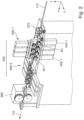
- the Fig. 1 shows components of a wire processing system that is designed and set up to process elongated workpieces 110 in the form of metallic wires that are available as a workpiece supply in the form of a so-called coil, i.e. a wire bundle wound up like a coil.
- the molded parts can be, for example, coil springs, in particular compression springs or tension springs, or bent parts of a different geometry. Molded parts can generally be bent two-dimensionally or three-dimensionally, and can also be in the form of straight rods (e.g. in straightening machines or rod assembly machines).
- the Cartesian xyz machine coordinate system serves to better describe directions and positional relationships.
- the wire processing system comprises a forming machine (not shown) which can be designed as a spring winding machine, for example, in the production of coil springs.
- a device 300 is provided for feeding the elongated wire-shaped workpiece material to the forming machine.
- the device 300 is also referred to in this application as feeding device 300 for short.
- the feeding device of the exemplary embodiment is a forming machine that produces a straightened wire from more or less strongly curved wire of the wound wire supply by forming.
- Fig. 1 shows some components of the feeding device 300 together with an associated measuring unit 350 of a feeding system.
- One task of the feeding device 300 is to feed the wire in a straightened form (residual curvature close to zero within the tolerance range) to a downstream forming machine or its feed device at any time as precisely as possible at the speed required at that time.
- the feeding device 300 has its own control unit 390, which communicates with the control unit of the forming machine.
- the functionalities of the two control units can be integrated in a single control unit.
- the feeding device After completing the setup at the setup station, the feeding device is moved to its working position on the forming machine to be supplied.
- the components shown are mounted on a movable platform, which can be moved linearly on guide rails, or mounted so that it can rotate around a vertical axis of rotation, or can be moved unguided (e.g. on rollers or wheels).
- the feeding device comprises a feeding unit 310, which has a receiving device 330 for receiving a workpiece supply 381 in the form of a coil and a downstream straightening system 400 for straightening the workpiece before it enters the forming machine.
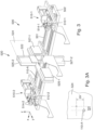
- the straightening system 400 is in Fig. 2 shown in detail.
- Fig. 1 shows the feed unit 310 at a measuring unit 350 or a setup station 350, which enables a machine operator to carry out all the work required on a straightening system 400 located at the measuring unit or the setup station 350. are to adjust the straightening system to the workpiece material used in such a way that the feed unit can deliver straightened workpiece material with a high straightening quality during productive operation, i.e. when the feed unit is in its working position on a forming machine, in particular material with no residual curvature or with residual curvature only within the tolerance range.
- the workpiece supply (coil) is kept on an exchangeable reel 335, which is picked up by a receiving device 330 and, when picked up, is mounted so that it can rotate about a horizontal axis of rotation.
- the storage does not take place in the area of the reel's axis of rotation; instead, two axially parallel support rollers 332, 333 with horizontal axes of rotation are attached in the base area. These support rollers are components of the receiving device 330.
- the reel is placed on the two support rollers so that the circumference of the disc-shaped side elements of the reel rests on the two support rollers and the position of the axis of rotation in space is fixed. In the example case, this is an active reel with its own drive.
- the drive 334 is in engagement with the front support roller 333 and can drive it under the control of the control unit 390.
- the unwound wire is guided over a deflection device 340, which has an upper deflection roller 340-1 and a lower deflection roller 340-2, which are mounted on a vertical support 341 so that they can rotate parallel to the axis.
- the upper deflection roller is designed as a vertically movable dancer roller with spring return.
- the drive motor for the support/drive roller is controlled by a position query of this roller.
- the lower deflection roller is wrapped around approximately three quarters of its circumference in such a way that the outlet, i.e. the top of the lower deflection roller 340, is at the level of the inlet-side passage opening of the straightening system 400.
- the wire is therefore guided essentially horizontally from the lower deflection roller to the straightening system 400.
- a wire guide device 375 Between the deflection device and the straightening system there is a wire guide device 375, the output of which is aligned with the input of the downstream straightening system 400.
- a wire end detection device can be integrated into the wire guide device.
- FIG. 1 An alternative construction belonging to the claimed invention is shown in Fig. 1 shown or indicated with dashed lines.
- the construction comprises a buffer storage 600 in the form of a relatively flat storage box that is open on one side (here partially upwards) and an upstream auxiliary feed device 610, which can be arranged behind the upper deflection roller 340-1, for example. can.
- the auxiliary feed device can be driven by means of an auxiliary drive and is configured to feed the workpiece, in the example the wire, at a predeterminable conveying speed to the downstream buffer storage 600.
- the buffer storage has an inlet and an outlet for the workpiece.
- the buffer storage is designed in such a way that the workpiece in the buffer storage can form a workpiece loop 111 of variable length between the inlet and the outlet. Speed differences between the areas in front of and behind the buffer storage can thus be compensated.
- a sensor system is provided for detecting the filling level of the buffer storage and for generating sensor signals representing the filling level.
- the control device can then be configured in such a way that the conveying speed of the auxiliary feed device can be controlled or is controlled depending on sensor signals from the sensor system.
- a buffer storage can also be installed horizontally if required, so that the workpiece loop forms in a plane that is essentially horizontally aligned.
- the straightening system 400 comprises two roller straightening devices 400-1, 400-2, which are connected directly one after the other and can be adjusted independently of one another and each have a number of axially parallel straightening rollers. Seven straightening rollers are provided here, but other numbers, e.g. five to nine, are also possible.
- the axes of rotation of the straightening rollers of the straightening devices connected one after the other are aligned orthogonally to one another.
- straightening rollers In a roller straightening device, straightening rollers generate alternating bends due to an off-center setting in relation to a neutral axis of the material to be straightened, which deform the material to be straightened into the plastic range and thus straighten it.
- the straightening rollers In contrast to a roller straightening machine, the straightening rollers here are passive or not rotationally driven, so there are no drives for rotating the straightening rollers.
- the wire is pulled through the roller straightening devices.
- a feed device 385 is provided, which is arranged behind the straightening system 400 in the direction of material flow and serves, among other things, to pull the wire material through the two roller straighteners 400-1, 400-2 of the straightening system 300 in the direction of subsequent components.
- the components of the straightening system 400 are supported by a frame part, in which the control unit 390 of the feed unit 310 can also be accommodated.
- the frame part also supports the feed device 385.
- the feed device 385 is designed as a roller feed in the example and can also be designed as a Belt feed device or pliers feed device.
- an optional, possibly manually operable clamping device can be provided with which the axial position of the wire passed through can be fixed if necessary.
- first roller straightening device 400-1 which operates in the vertical plane (x-z plane).
- the first roller straightening device 400-1 has seven passive straightening rollers R1, ... R7 with mutually parallel, horizontal axes of rotation, which are arranged alternately on opposite sides of a passage path (parallel to the x-axis) in a throughput direction 115.
- the straightening rollers define the effective straightening geometry of the roller straightening device with their circumferential sections touching the material 110 to be straightened.
- the first roller straightening device 400-1 essentially changes the curvature only in a vertical plane (x-z plane), the straightening plane.
- the second roller straightening device 400-2 which is responsible for straightening in a horizontal plane, is constructed in an analogous manner; here the straightening roller axes of rotation run vertically.
- all seven straightening rollers are designed as automatically adjustable straightening rollers and can be automatically adjusted bidirectionally in response to control signals from the control unit 390 by means of servomotor drives 405-1, ..,, 405-7 independently of one another in a feed direction oriented perpendicular to the direction of travel (parallel to the z-axis).
- all of the straightening rollers can be adjusted manually.
- adjustment screws and position indicators can be provided for this purpose.
- a proportion of the straightening rollers e.g. two, three or four
- another proportion e.g. three, four or five
- the setup is made easier by the fact that the feed system includes a measuring unit 350 which is adapted to the structural and functional conditions of the feed device 300 and which enables a targeted setup procedure in a short time.
- the measuring unit 350 serves as a setup station.
- the measuring unit or the setup station 350 comprises a cutting device 370, with which, during the adjustment work on the straightening system, rod-shaped wire sections 110-A are cut off from the supplied wire on a trial basis and thus made available for a straightness test.
- a cutting device 370 In the example case, an automated cutting device 370 is provided; alternatively, a manually operated cutting device can be provided.
- the setup station 350 also has a measuring device 500.
- the wire sections or wire rods 110-A cut off by the cutting device are checked for straightness or residual curvatures using the downstream measuring device 500.
- Anti-twist devices are used to ensure that the rotational position of the material rod intended for measurement remains unchanged around its longitudinal axis, so that the wire is measured in the rotational position in which it ran through the straightening system.
- the measuring device 500 and the associated cutting device 370 are components of the measuring unit 350, which, optionally together with other components, forms an autonomous unit that can serve as a setup station 350. Therefore, the same reference numeral 350 is used for the setup station and the measuring unit.
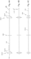
- Fig. 3 shows an enlarged detailed view of components of the measuring device 500.
- the measuring device 500 comprises a first clamping device 510-1 on the side facing the cutting device 370 and a second clamping device 510-2 at a distance behind it.
- the clamping devices are mounted on carriages that run on two guide rails 501 that are attached to the top of a horizontally aligned base plate 502. The axial distance of the clamping devices, measured parallel to the direction of travel, can thus be continuously adjusted.
- Each of the clamping devices has a support roller 512-1, 512-2 mounted with a horizontal axis of rotation and two pneumatically adjustable transverse positioning rollers 514-1, 514-2. This allows an inserted wire rod to be fixed at a precisely defined fixing point in both the vertical and horizontal directions.
- the rollers contact the wire without introducing any additional forces or torques, so that the wire rod rests at defined fixation positions at the front and back and is only subject to gravity in the area in between.
- the rod cannot rotate about its axis if it is gently clamped between the horizontally movable rollers 514-1, 514-2.
- Components of a measuring system 520 are mounted in the area between the clamping devices 510-1, 510-2. These are supported by a cross-shaped carrier 522, which is mounted on a carriage which can be moved on the guide rails 501, which also guide the clamping devices.
- the measuring system 520 is an optical measuring system which can determine the position of the applied wire in a measuring plane 524 oriented perpendicular to the x-direction with high precision.
- a second laser unit 525-2 is mounted, which generates a laser light curtain lying in the measuring plane 524, which falls into the detection range of a photosensitive sensor 527-2 on the opposite side, so that the position of the wire in the transverse direction (horizontal direction) can be precisely detected in the shadow cast.
- the position in the vertical direction is detected using a first laser unit 525-1 and the opposite sensor 527-1.
- the measurement is preferably carried out in the middle between the two fixing elements using the two lasers in the horizontal or vertical direction.
- Fig. 3A illustrates a typical measurement situation.
- the plus symbol represents the intersection of the connecting line between the fixation points and the measurement plane 524.
- the hatched circle represents the position of the wire section 110-A in the middle between the clamping devices.
- a residual curvature of the wire rod in the respective straightening planes can be calculated from the distance values ⁇ H in the horizontal direction and ⁇ V in the vertical direction. The results are therefore specific to the straightening plane and are evaluated accordingly in order to provide instructions for improving the straightening geometry, determined separately for each of the two roller straightening devices if necessary.
- the evaluation takes into account that the wire rod experiences a certain amount of deflection due to gravity alone, the extent of which depends on the material properties and the distance between the fixation points. This contribution is eliminated during the evaluation.
- the result of the measurement is a quantitative value for the residual curvature, which can have contributions in both the horizontal and vertical directions. Based on these measured values, the straightening geometry of the roller straightening devices should then be adjusted so that the residual curvature disappears in the next piece of wire.
- the inventors see a potential problem in the processing of round material. It is possible that a round bar that still has a significant bulge in the horizontal plane after straightening will automatically roll into a stable rotational position when it is placed in the measuring device, in which the bulge sags downwards. This would simulate a bulge in the vertical direction that is not actually present, which would lead to incorrect measurement results and, as a result, incorrect feeds and/or incorrect feeds at the wrong point on the straightening device.
- the measuring unit 350 is configured for a straightening plane-specific or straightening plane-selective measurement. This is explained in more detail below using examples.
- the schematically illustrated method variant is suitable for many materials with different cross-sectional shapes, in particular also for round material.
- the procedure is such that first the front end section 112 of the straightened wire adjoining the front face 113 is conveyed to a measuring position in the measuring device 500 by means of a controlled feed (by the upstream feed device 385) ( Fig. 4A ), then by means of the transversely movable rollers 514-1 or 514-2, the clamping devices 510-1, 510-2 are contacted on diametrically opposite sides and are thereby clamped horizontally and thus prevented from rotating ( Fig. 4B ) and that only then the rod to be measured is separated from the rest of the target material ( Fig. 4C ). The measurement then begins using the optical measuring system 520.
- the horizontally movable rollers 514-1 and 514-2 of the clamping devices act as an anti-twisting device, contacting the wire material at two contact points diametrically opposite in the horizontal direction with a relatively low pressure, which is dimensioned such that the static friction is sufficient to prevent the rod from rotating around its longitudinal axis, but at the same time the wire rod can relax so that it is otherwise free of forces except for gravity and thus shows the residual curvatures that are to be measured.
- the wire with a flat rectangular cross-section (see detail) is fed through the wire feed by means of the feed device 385 to a cutting position. This is characterized, among other things, by the fact that the front end 113 of the bar has already reached the support roller of the rear or second clamping device 510-2 and is resting there. During this threading operation, the cross positioning rollers are in their retracted position. The cut is then made using the cutting device 370 ( Fig. 5B ). In the next step ( Fig.
- the cut piece of wire is pushed further forward into its measuring position, in which the wire rod is centered in relation to the measuring plane in the middle and protrudes on both sides by equal lengths over the support roller.
- no separate device is required. Rather, the following piece of wire is moved to the rear end of the wire rod to be measured by means of the feed device 385, so that it can cause the horizontal feed in the manner of a ram.
- the cross positioning rollers are moved in the direction of the intended fixing positions using their pneumatic cylinders.
- the piece of wire is pressed onto the rear stop to ensure a defined plane. This fixes the wire rod for the measurement. It is easy to see that the connecting line between the front and rear fixing positions does not have to be coaxial with the feed axis of the following wire.
- a measuring unit of the type described here can also be used in other ways.
- the straightening system can have exactly two roller straighteners, which preferably produce straightening planes that are perpendicular to one another.
- a straightening system can also have three or four or more roller straighteners.
- a straightening system can have four straighteners, each offset by 45°, which can be a favorable variant for straightening round wire, for example.
- the forming machine into which the straightening system is integrated can also be a straightening and cutting machine that is designed to straighten wires or other semi-finished materials that can be processed by straightening and have different cross-sectional sizes and shapes, and then cut the straightened straightened material to a desired length.
- the machine then also has a length measuring device and a cutting device that can preferably be operated automatically based on signals from the length measuring device.
- the measuring unit can then measure the separated straightened bars.
- the measuring unit does not need its own cutting device for this.
- It can also be a bar processing machine that, in addition to the straightening system, a cutting device and a length measuring device, also has a stripping device to remove sections of the insulation from a metallic starting material covered with an insulating layer.
- a straightening system can also be integrated into a forming machine, which can use suitable forming tools to produce smaller or larger series of molded parts, some of which have complex geometries, from the straightened material in an automatic production process.
- the forming tools required for forming are then connected downstream of the straightening system.
- the forming machine can be, for example, a bending machine for producing bent parts from wire material, strip material or pipe material, or a spring manufacturing machine or a wire pin machine for mass production of screws, nails, rivets or the like.
- the measuring unit can be used, for example, to measure the wire emerging from a wire guide of the respective machine.
- the invention can be used for different types of straightening material, in particular for straightening metallic wire material or pipe material.
- the cross-sectional shape of the straightening material can be different, e.g. a circular cross-section for round material, a profiled and/or polygonal cross-section for profile material, in particular a rectangular cross-section for square material.
- Flat material such as metallic flat strips with a large aspect ratio between width and height, can also be straightened.
- the cross-sectional size can also vary.
- the metallic material can be uncoated or have a coating, e.g. an electrically non-conductive insulating layer made of plastic.
- the straightness test or measurement does not have to be carried out as described in the example.
- the straightness test can also be carried out automatically using at least one camera.
- the straightness can also be checked in transit using two cameras offset by 90°.
- a camera rotating around the wire or a laser scanner can be used, particularly with round wires.
Landscapes
- Engineering & Computer Science (AREA)
- Mechanical Engineering (AREA)
- Wire Processing (AREA)
Claims (14)
- Système d'alimentation, comprenant :un dispositif d'alimentation (300) pour amener une pièce (110) allongée, filiforme ou tubulaire, à une machine de formage, dans lequel le dispositif d'alimentation présente un équipement de réception (330) pour recevoir une réserve de pièces sous la forme d'une bobine (381) et un système de dressage (400) placé en aval de l'équipement de réception, avec deux appareils de dressage à galets (400-1, 400-2) réglables, montés l'un après l'autre, avec des plans de dressage orientés différemment pour dresser la pièce avant son entrée dans la machine de formage ;une unité de mesure (350) pour mesurer des courbures résiduelles sur un produit à dresser filiforme ou tubulaire dressé et qui est passé par le système de dressage (400) du dispositif d'alimentation (300), et pour établir des données de mesure qui représentent une courbure résiduelle du produit à dresser,dans lequel l'unité de mesure est configurée pour une mesure spécifique à un plan de dressage qui permet une attribution des pourcentages de courbure représentés par les données de mesure aux différents plans de dressage des appareils de dressage à galets,caractérisé en ce queun équipement de coupe (370) est prévu pour séparer des tronçons (110-A) en forme de barre d'une longueur prédéfinissable du produit à dresser qui est passé par le système de dressage (400) ;l'unité de mesure (350) présente un dispositif de mesure (520) pour recevoir dans une position de mesure respectivement un tronçon (110-A) en forme de barre, séparé du produit à dresser, du produit à dresser qui est passé par le système de dressage.
- Système d'alimentation selon la revendication 1, caractérisé en ce que l'unité de mesure (350) présente l'équipement de coupe (370) pour séparer des tronçons (110-A) en forme de barre d'une longueur prédéfinissable du produit à dresser qui est passé par le système de dressage, dans lequel de préférence l'équipement de coupe (370) est monté conjointement avec le dispositif de mesure (500) sur ou au niveau d'un bâti commun.
- Système d'alimentation selon la revendication 1 ou 2, caractérisé en ce que l'unité de mesure (350) est configurée de telle sorte que le produit à dresser peut être mesuré dans la position de rotation dans laquelle il est passé par le système de dressage (400).
- Système d'alimentation selon l'une quelconque des revendications précédentes, caractérisé par des équipements antirotation (514-1, 514-2) qui sont configurés de telle sorte qu'une position de rotation d'un tronçon (110-A) en forme de barre séparé, prévu pour la mesure, reste inchangée autour de son axe longitudinal entre le dressage et la mesure de telle sorte que le produit à dresser peut être mesuré dans la position de rotation dans laquelle il est passé par le système de dressage, dans lequel de préférence des équipements antirotation pouvant être actionnés sont prévus qui peuvent commuter en réponse à des signaux de commande d'une unité de commande entre une configuration neutre sans intervention sur le produit à dresser et une configuration d'intervention en contact avec le produit à dresser.
- Système d'alimentation selon l'une quelconque des revendications précédentes, caractérisé par une unité de commande (390) qui est configurée dans un mode de fonctionnement de telle sorte que l'équipement de coupe (370) et le dispositif de mesure (500) sont pilotés de manière coordonnée, en ce qu'un tronçon d'extrémité avant (112) du produit à dresser dressé est transporté au moyen d'une avance commandée vers une position de mesure dans le dispositif de mesure (500), le produit à dresser est ensuite verrouillé en rotation au moyen d'équipements antirotation (514-1, 514-2) de l'unité de mesure (350), en particulier serré dans la direction horizontale, et ensuite l'équipement de coupe (390) est piloté pour séparer du reste du produit à dresser le tronçon en forme de barre à mesurer.
- Système d'alimentation selon l'une quelconque des revendications précédentes, caractérisé en ce que le dispositif de mesure (500) présente sur un côté entrée un premier dispositif de serrage (510-1) et à une distance de celui-ci dans la direction longitudinale un deuxième dispositif de serrage (510-2), dans lequel, dans une zone entre les dispositifs de serrage (510-1, 510-2) sont disposés des composants d'un système de mesure (520) qui définit un plan de mesure (524) orienté transversalement, en particulier verticalement à la direction longitudinale, et est conçu pour déterminer la position du tronçon (110-A) en forme de barre posé dans le plan de mesure (524), dans lequel de préférence chacun des dispositifs de serrage présente un galet d'appui (512-1, 512-2) monté avec un axe de rotation horizontal et deux galets de positionnement transversaux (514-1, 514-2) réglables au moyen d'un dispositif d'entraînement de telle sorte qu'un tronçon en forme de barre introduit peut être fixé respectivement en un point de fixation défini dans la direction verticale et dans la direction horizontale.
- Système d'alimentation selon la revendication 6, caractérisé en ce qu'une distance mesurée en parallèle à la direction longitudinale des dispositifs de serrage (510-1, 510-2) est réglable en continu, dans lequel de préférence les dispositifs de serrage sont montés sur des chariots qui glissent sur des rails de guidage (501) qui sont fixés à la face supérieure d'une plaque de base (502), alignée horizontalement, du système de mesure, et/ou des composants du dispositif de mesure sont fixés à un support (522) qui est monté sur un chariot qui est mobile sur les rails de guidage (501) qui guident également les dispositifs de serrage.
- Système d'alimentation selon l'une quelconque des revendications précédentes, caractérisé en ce qu'un système de mesure (520) du dispositif de mesure est un système de mesure optique pour déterminer la position du tronçon en forme de barre dans un plan de mesure (524) situé entre les dispositifs de serrage, dans lequel de préférence le système de mesure présente une première unité laser 525-1 et une deuxième unité laser 525-2 qui produisent dans des directions de mesure orientées transversalement, en particulier verticalement, l'une par rapport à l'autre respectivement un rideau de lumière laser s'étendant dans le plan de mesure, dans lequel respectivement en face d'une unité laser est disposée une unité de capteur avec des capteurs photosensibles pour détecter une ombre portée de la pièce traversant le plan de mesure du tronçon en forme de barre (110-A).
- Système d'alimentation selon l'une quelconque des revendications précédentes, caractérisé en ce que la réserve de pièces est enroulée sur un dévidoir (335) échangeable et l'équipement de réception (330) est réalisé de telle sorte que le dévidoir peut être reçu par le dispositif de réception (330) et est logé à l'état reçu en rotation autour d'un axe de rotation horizontal.
- Système d'alimentation selon l'une quelconque des revendications précédentes, caractérisé en ce que le dispositif de réception (330) présente deux galets porteurs (332, 333) parallèles à l'axe avec des axes de rotation horizontaux sur lesquels le dévidoir (335) peut être posé de telle sorte que la circonférence des éléments latéraux du dévidoir repose sur les deux galets porteurs et la position de l'axe de rotation est définie dans l'espace, dans lequel de préférence un dispositif d'entraînement (334) pouvant être piloté par une unité de commande est prévu qui est en prise avec l'un des galets porteurs (333) et peut les entraîner en étant commandé par l'unité de commande 390.
- Système d'alimentation selon l'une quelconque des revendications précédentes, caractérisé en ce que le dispositif de réception (330) présente un équipement de renvoi (340) avec une poulie de renvoi supérieure (340-1) pour recevoir la pièce déroulée de la réserve de pièces ainsi qu'un équipement disposé au-dessous de la poulie de renvoi supérieure (340-1) pour recevoir une boucle de pièce avant son entrée dans le système de dressage (400).
- Système d'alimentation selon la revendication 11, caractérisé en ce que l'équipement disposé au-dessous de la poulie de renvoi supérieure (340-1) pour recevoir une boucle de pièce (111) présente un stockage tampon (600) orienté verticalement sous la forme d'une caisse de stockage partiellement ouverte vers le haut et un équipement d'entrée auxiliaire (610), disposé entre la poulie de renvoi supérieure (340-1) et le stockage tampon (600), qui peut être entraîné au moyen d'un dispositif d'entraînement auxiliaire et est configuré pour transporter la pièce à une vitesse de transport prédéfinissable jusqu'au stockage tampon (600), dans lequel de préférence un système de capteur est prévu pour détecter le degré de remplissage du stockage tampon et pour produire des signaux de capteur représentant le degré de remplissage, dans lequel un équipement de commande est configuré de telle sorte que la vitesse de transport de l'équipement d'entrée auxiliaire peut être commandée en fonction des signaux de capteur du système de capteur.
- Système d'alimentation selon la revendication 11, caractérisé en ce que l'équipement, disposé en-dessous de la poulie de renvoi supérieure (340-1), pour recevoir une boucle de pièce présente une poulie de renvoi inférieure (340-2), la poulie de renvoi supérieure (340-1) et la poulie de renvoi inférieure (340-2) étant montées en rotation parallèle à l'axe sur un support vertical (341), dans lequel de préférence la poulie de renvoi supérieure est réalisée comme un rouleau libre, verticalement mobile, avec position de rappel par ressort, et une interrogation de position de cette poulie de renvoi est utilisée pour réguler un moteur d'entraînement (334) pour la rotation du dévidoir, et/ou dans lequel la poulie de renvoi est enroulée sur environ trois quarts de sa circonférence et présente sur sa face supérieure une sortie qui se trouve à la hauteur d'une ouverture de passage côté entrée du système de dressage (400) de sorte que le matériau de la pièce peut entrer dans le système de dressage (400) depuis la poulie de renvoi inférieure directement dans la direction horizontale.
- Système d'alimentation selon l'une quelconque des revendications précédentes, caractérisé en ce que le système de dressage (400) présente deux appareils de dressage à galets (400-1, 400-2) placés l'un après l'autre et réglables indépendamment l'un de l'autre, dans lequel les axes de rotation des galets de dressage des appareils de dressage sont alignés orthogonalement l'un par rapport à l'autre, de préférence de telle sorte qu'un premier appareil de dressage définit un plan de dressage vertical et un deuxième appareil de dressage suivant définit un plan de dressage horizontal.
Applications Claiming Priority (2)
| Application Number | Priority Date | Filing Date | Title |
|---|---|---|---|
| DE102021212059.8A DE102021212059A1 (de) | 2021-10-26 | 2021-10-26 | Zuführsystem |
| PCT/EP2022/079559 WO2023072819A1 (fr) | 2021-10-26 | 2022-10-24 | Système d'alimentation |
Publications (3)
| Publication Number | Publication Date |
|---|---|
| EP4408596A1 EP4408596A1 (fr) | 2024-08-07 |
| EP4408596C0 EP4408596C0 (fr) | 2025-02-05 |
| EP4408596B1 true EP4408596B1 (fr) | 2025-02-05 |
Family
ID=84361392
Family Applications (1)
| Application Number | Title | Priority Date | Filing Date |
|---|---|---|---|
| EP22809682.2A Active EP4408596B1 (fr) | 2021-10-26 | 2022-10-24 | Système d'alimentation |
Country Status (7)
| Country | Link |
|---|---|
| US (1) | US20250010358A1 (fr) |
| EP (1) | EP4408596B1 (fr) |
| JP (1) | JP2024542951A (fr) |
| CN (1) | CN118159369A (fr) |
| DE (1) | DE102021212059A1 (fr) |
| MX (1) | MX2024004954A (fr) |
| WO (1) | WO2023072819A1 (fr) |
Families Citing this family (3)
| Publication number | Priority date | Publication date | Assignee | Title |
|---|---|---|---|---|
| DE102023126784A1 (de) | 2023-10-02 | 2025-04-03 | Wafios Aktiengesellschaft | Verfahren und System zum Einrichten eines Richtsystems |
| EP4589248A1 (fr) * | 2024-01-18 | 2025-07-23 | Progress Maschinen & Automation AG | Procédé de mesure d'une propriété d'une tige |
| CN120790793B (zh) * | 2025-09-12 | 2025-12-09 | 吉林省路桥工程(集团)有限公司 | 一种具有自动定位功能的u型钢筋加工设备 |
Family Cites Families (12)
| Publication number | Priority date | Publication date | Assignee | Title |
|---|---|---|---|---|
| JPS6182939A (ja) * | 1984-10-01 | 1986-04-26 | Nippon Steel Weld Prod & Eng Co Ltd | 鋼線材の曲り矯正装置 |
| JPH05337582A (ja) * | 1992-06-12 | 1993-12-21 | Furukawa Electric Co Ltd:The | 線状体の整直方法 |
| DE19503850C1 (de) | 1995-02-06 | 1996-06-13 | Post Friedhelm Sondermasch | Nichtrotierender Richtapparat für Biegemaschinen mit integrierter Meßvorrichtung |
| JP2003221163A (ja) * | 2002-01-31 | 2003-08-05 | Nippon Koshuha Steel Co Ltd | ボビン繰り出し線材の張力制御方法及びその装置 |
| JP2011143423A (ja) * | 2010-01-13 | 2011-07-28 | Sanyo Special Steel Co Ltd | 鋼線コイルの湾曲矯正作業台 |
| DE102011004167B4 (de) | 2011-02-15 | 2015-05-13 | Institut Dr. Foerster Gmbh & Co. Kg | Verfahren und Vorrichtung zum automatisierten Richten von langgestrecktem Material |
| US8763436B2 (en) * | 2011-07-08 | 2014-07-01 | L&P Property Management Company | Servo-controlled three axis wire straightening device |
| ITUA20162848A1 (it) * | 2016-04-22 | 2017-10-22 | Schnell Spa | Metodo per regolare automaticamente la raddrizzatura di elementi metallici di foggia allungata e apparecchiatura per raddrizzare gli stessi elementi |
| AT518731B1 (de) | 2016-05-27 | 2019-05-15 | Progress Holding Ag | Richtmaschine |
| IT201700073093A1 (it) * | 2017-06-29 | 2018-12-29 | Rde Company S R L | Sistema di trattamento di corpi snelli in un impianto di lavorazione e controllo |
| WO2020224977A1 (fr) | 2019-05-07 | 2020-11-12 | Wafios Aktiengesellschaft | Procédé et arrangement d'acheminement d'une pièce ouvrée allongée à une machine de façonnage |
| DE102020212480A1 (de) | 2020-10-02 | 2022-04-07 | Wafios Aktiengesellschaft | Verfahren und Vorrichtung zum Zuführen eines langgestreckten Werkstücks zu einer Umformmaschine |
-
2021
- 2021-10-26 DE DE102021212059.8A patent/DE102021212059A1/de not_active Withdrawn
-
2022
- 2022-10-24 MX MX2024004954A patent/MX2024004954A/es unknown
- 2022-10-24 JP JP2024523467A patent/JP2024542951A/ja active Pending
- 2022-10-24 WO PCT/EP2022/079559 patent/WO2023072819A1/fr not_active Ceased
- 2022-10-24 US US18/705,214 patent/US20250010358A1/en active Pending
- 2022-10-24 EP EP22809682.2A patent/EP4408596B1/fr active Active
- 2022-10-24 CN CN202280072403.XA patent/CN118159369A/zh active Pending
Also Published As
| Publication number | Publication date |
|---|---|
| CN118159369A (zh) | 2024-06-07 |
| WO2023072819A1 (fr) | 2023-05-04 |
| EP4408596A1 (fr) | 2024-08-07 |
| MX2024004954A (es) | 2024-05-08 |
| DE102021212059A1 (de) | 2023-04-27 |
| US20250010358A1 (en) | 2025-01-09 |
| JP2024542951A (ja) | 2024-11-19 |
| EP4408596C0 (fr) | 2025-02-05 |
Similar Documents
| Publication | Publication Date | Title |
|---|---|---|
| EP4408596B1 (fr) | Système d'alimentation | |
| WO2023072818A1 (fr) | Unité de mesure et procédé de mesure pour la mesure d'un produit à dresser en forme de fil ou de tube dressé | |
| EP4221910B1 (fr) | Procédé et appareil d'acheminement d'une pièce allongée dans une machine de formage | |
| DE102019206619B4 (de) | Messverfahren und Messvorrichtung zum Messen der Geradheit von Rundmaterialstücken | |
| DE102010014386B4 (de) | Verfahren zur Herstellung von Schraubenfedern durch Federwinden, sowie Federwindemaschine | |
| DE102007059185B4 (de) | Verfahren und Vorrichtung zur Messung der Geradheit von Langprodukten | |
| DE102015208350B3 (de) | Verfahren zur Herstellung von Formteilen und Umformmaschine zur Durchführung des Verfahrens | |
| DE102012109245B3 (de) | Verfahren und Vorrichtung zur Bearbeitung von nicht-rotationssymmetrischen Werkstücken mittels Laserstrahlung | |
| WO1996017701A1 (fr) | Procede et dispositif de production optimisee de ressorts helicoidaux sur des machines automatiques a enrouler les ressorts | |
| DE202018006880U1 (de) | Apparat zum Messen des Geradheitsfehlers von schlanken Körpern, mit Ausgleich der schwerkraftbedingten Verformung sowie System mit einem solchen Apparat | |
| EP3126073B1 (fr) | Procédé et machine à enrouler les ressorts pour la production de ressorts hélicoïdaux par enroulement | |
| DE102016217202B4 (de) | Regelung des Betriebs einer Walzstraße | |
| DE102020216047B3 (de) | Verfahren und Umformmaschine zur Herstellung von Formteilen aus Rundmaterial | |
| DE102018205610A1 (de) | Richt- und Abschneidemaschine | |
| EP4594030A1 (fr) | Procédé et installation de fabrication pour produire des barres conductrices | |
| DE102022203993A1 (de) | Messeinheit und Messverfahren zum Messen von gerichtetem draht- oder rohrförmigen Richtgut | |
| DE102021212056A1 (de) | Messeinheit und Messverfahren zum Messen von gerichtetem draht- oder rohrförmigen Richtgut | |
| EP3572161B1 (fr) | Procédé et dispositif de fabrication d'un produit de matériau en bande laminé flexible | |
| EP2492630B1 (fr) | Dispositif de mesure de la forme d'une tige | |
| DE102022119892A1 (de) | Verfahren und Vorrichtung zum Positionieren sowie Verfahren und Vorrichtung zum Bearbeiten eines plattenartigen Werkstücks, insbesondere eines Blechs | |
| EP2301687A1 (fr) | Procédé et dispositif de pliage de matériaux tubulaires ou en forme de tiges | |
| DE102021208335A1 (de) | Geradheitsmessung länglicher Werkstücke in der metallverarbeitenden Industrie | |
| WO2021028204A1 (fr) | Machine de formage dotée d'un dispositif d'alimentation | |
| EP1459034B1 (fr) | Procede et dispositif pour mesurer des longueurs sur une piece pliee | |
| EP4680417A1 (fr) | Dispositif de redressage automatique de matériau allongé à redresser et procédé associé |
Legal Events
| Date | Code | Title | Description |
|---|---|---|---|
| STAA | Information on the status of an ep patent application or granted ep patent |
Free format text: STATUS: UNKNOWN |
|
| STAA | Information on the status of an ep patent application or granted ep patent |
Free format text: STATUS: THE INTERNATIONAL PUBLICATION HAS BEEN MADE |
|
| PUAI | Public reference made under article 153(3) epc to a published international application that has entered the european phase |
Free format text: ORIGINAL CODE: 0009012 |
|
| STAA | Information on the status of an ep patent application or granted ep patent |
Free format text: STATUS: REQUEST FOR EXAMINATION WAS MADE |
|
| 17P | Request for examination filed |
Effective date: 20240502 |
|
| AK | Designated contracting states |
Kind code of ref document: A1 Designated state(s): AL AT BE BG CH CY CZ DE DK EE ES FI FR GB GR HR HU IE IS IT LI LT LU LV MC ME MK MT NL NO PL PT RO RS SE SI SK SM TR |
|
| GRAP | Despatch of communication of intention to grant a patent |
Free format text: ORIGINAL CODE: EPIDOSNIGR1 |
|
| STAA | Information on the status of an ep patent application or granted ep patent |
Free format text: STATUS: GRANT OF PATENT IS INTENDED |
|
| INTG | Intention to grant announced |
Effective date: 20241028 |
|
| GRAS | Grant fee paid |
Free format text: ORIGINAL CODE: EPIDOSNIGR3 |
|
| GRAA | (expected) grant |
Free format text: ORIGINAL CODE: 0009210 |
|
| STAA | Information on the status of an ep patent application or granted ep patent |
Free format text: STATUS: THE PATENT HAS BEEN GRANTED |
|
| AK | Designated contracting states |
Kind code of ref document: B1 Designated state(s): AL AT BE BG CH CY CZ DE DK EE ES FI FR GB GR HR HU IE IS IT LI LT LU LV MC ME MK MT NL NO PL PT RO RS SE SI SK SM TR |
|
| DAV | Request for validation of the european patent (deleted) | ||
| DAX | Request for extension of the european patent (deleted) | ||
| REG | Reference to a national code |
Ref country code: GB Ref legal event code: FG4D Free format text: NOT ENGLISH |
|
| REG | Reference to a national code |
Ref country code: CH Ref legal event code: EP |
|
| REG | Reference to a national code |
Ref country code: IE Ref legal event code: FG4D Free format text: LANGUAGE OF EP DOCUMENT: GERMAN |
|
| REG | Reference to a national code |
Ref country code: DE Ref legal event code: R096 Ref document number: 502022002831 Country of ref document: DE |
|
| U01 | Request for unitary effect filed |
Effective date: 20250205 |
|
| U07 | Unitary effect registered |
Designated state(s): AT BE BG DE DK EE FI FR IT LT LU LV MT NL PT RO SE SI Effective date: 20250211 |
|
| PG25 | Lapsed in a contracting state [announced via postgrant information from national office to epo] |
Ref country code: RS Free format text: LAPSE BECAUSE OF FAILURE TO SUBMIT A TRANSLATION OF THE DESCRIPTION OR TO PAY THE FEE WITHIN THE PRESCRIBED TIME-LIMIT Effective date: 20250505 |
|
| PG25 | Lapsed in a contracting state [announced via postgrant information from national office to epo] |
Ref country code: PL Free format text: LAPSE BECAUSE OF FAILURE TO SUBMIT A TRANSLATION OF THE DESCRIPTION OR TO PAY THE FEE WITHIN THE PRESCRIBED TIME-LIMIT Effective date: 20250205 |
|
| PG25 | Lapsed in a contracting state [announced via postgrant information from national office to epo] |
Ref country code: ES Free format text: LAPSE BECAUSE OF FAILURE TO SUBMIT A TRANSLATION OF THE DESCRIPTION OR TO PAY THE FEE WITHIN THE PRESCRIBED TIME-LIMIT Effective date: 20250205 |
|
| PG25 | Lapsed in a contracting state [announced via postgrant information from national office to epo] |
Ref country code: IS Free format text: LAPSE BECAUSE OF FAILURE TO SUBMIT A TRANSLATION OF THE DESCRIPTION OR TO PAY THE FEE WITHIN THE PRESCRIBED TIME-LIMIT Effective date: 20250605 Ref country code: NO Free format text: LAPSE BECAUSE OF FAILURE TO SUBMIT A TRANSLATION OF THE DESCRIPTION OR TO PAY THE FEE WITHIN THE PRESCRIBED TIME-LIMIT Effective date: 20250505 |
|
| PG25 | Lapsed in a contracting state [announced via postgrant information from national office to epo] |
Ref country code: HR Free format text: LAPSE BECAUSE OF FAILURE TO SUBMIT A TRANSLATION OF THE DESCRIPTION OR TO PAY THE FEE WITHIN THE PRESCRIBED TIME-LIMIT Effective date: 20250205 |
|
| PG25 | Lapsed in a contracting state [announced via postgrant information from national office to epo] |
Ref country code: GR Free format text: LAPSE BECAUSE OF FAILURE TO SUBMIT A TRANSLATION OF THE DESCRIPTION OR TO PAY THE FEE WITHIN THE PRESCRIBED TIME-LIMIT Effective date: 20250506 |
|
| PG25 | Lapsed in a contracting state [announced via postgrant information from national office to epo] |
Ref country code: SM Free format text: LAPSE BECAUSE OF FAILURE TO SUBMIT A TRANSLATION OF THE DESCRIPTION OR TO PAY THE FEE WITHIN THE PRESCRIBED TIME-LIMIT Effective date: 20250205 |
|
| PG25 | Lapsed in a contracting state [announced via postgrant information from national office to epo] |
Ref country code: CZ Free format text: LAPSE BECAUSE OF FAILURE TO SUBMIT A TRANSLATION OF THE DESCRIPTION OR TO PAY THE FEE WITHIN THE PRESCRIBED TIME-LIMIT Effective date: 20250205 |
|
| PG25 | Lapsed in a contracting state [announced via postgrant information from national office to epo] |
Ref country code: SK Free format text: LAPSE BECAUSE OF FAILURE TO SUBMIT A TRANSLATION OF THE DESCRIPTION OR TO PAY THE FEE WITHIN THE PRESCRIBED TIME-LIMIT Effective date: 20250205 |
|
| U20 | Renewal fee for the european patent with unitary effect paid |
Year of fee payment: 4 Effective date: 20251027 |
|
| PLBE | No opposition filed within time limit |
Free format text: ORIGINAL CODE: 0009261 |
|
| STAA | Information on the status of an ep patent application or granted ep patent |
Free format text: STATUS: NO OPPOSITION FILED WITHIN TIME LIMIT |
|
| 26N | No opposition filed |
Effective date: 20251106 |