EP4408098A1 - Referenzsignalübertragungsverfahren und -vorrichtung sowie zugehörige vorrichtung - Google Patents
Referenzsignalübertragungsverfahren und -vorrichtung sowie zugehörige vorrichtung Download PDFInfo
- Publication number
- EP4408098A1 EP4408098A1 EP22872097.5A EP22872097A EP4408098A1 EP 4408098 A1 EP4408098 A1 EP 4408098A1 EP 22872097 A EP22872097 A EP 22872097A EP 4408098 A1 EP4408098 A1 EP 4408098A1
- Authority
- EP
- European Patent Office
- Prior art keywords
- resource
- reference signal
- terminal
- prs
- priority
- Prior art date
- Legal status (The legal status is an assumption and is not a legal conclusion. Google has not performed a legal analysis and makes no representation as to the accuracy of the status listed.)
- Pending
Links
Images

Classifications
-
- H—ELECTRICITY
- H04—ELECTRIC COMMUNICATION TECHNIQUE
- H04W—WIRELESS COMMUNICATION NETWORKS
- H04W72/00—Local resource management
- H04W72/04—Wireless resource allocation
-
- H—ELECTRICITY
- H04—ELECTRIC COMMUNICATION TECHNIQUE
- H04L—TRANSMISSION OF DIGITAL INFORMATION, e.g. TELEGRAPHIC COMMUNICATION
- H04L5/00—Arrangements affording multiple use of the transmission path
- H04L5/0001—Arrangements for dividing the transmission path
- H04L5/0003—Two-dimensional division
- H04L5/0005—Time-frequency
- H04L5/0007—Time-frequency the frequencies being orthogonal, e.g. OFDM(A) or DMT
- H04L5/001—Time-frequency the frequencies being orthogonal, e.g. OFDM(A) or DMT the frequencies being arranged in component carriers
-
- H—ELECTRICITY
- H04—ELECTRIC COMMUNICATION TECHNIQUE
- H04L—TRANSMISSION OF DIGITAL INFORMATION, e.g. TELEGRAPHIC COMMUNICATION
- H04L5/00—Arrangements affording multiple use of the transmission path
- H04L5/003—Arrangements for allocating sub-channels of the transmission path
- H04L5/0032—Distributed allocation, i.e. involving a plurality of allocating devices, each making partial allocation
- H04L5/0033—Distributed allocation, i.e. involving a plurality of allocating devices, each making partial allocation each allocating device acting autonomously, i.e. without negotiation with other allocating devices
-
- H—ELECTRICITY
- H04—ELECTRIC COMMUNICATION TECHNIQUE
- H04L—TRANSMISSION OF DIGITAL INFORMATION, e.g. TELEGRAPHIC COMMUNICATION
- H04L5/00—Arrangements affording multiple use of the transmission path
- H04L5/003—Arrangements for allocating sub-channels of the transmission path
- H04L5/0048—Allocation of pilot signals, i.e. of signals known to the receiver
-
- H—ELECTRICITY
- H04—ELECTRIC COMMUNICATION TECHNIQUE
- H04L—TRANSMISSION OF DIGITAL INFORMATION, e.g. TELEGRAPHIC COMMUNICATION
- H04L5/00—Arrangements affording multiple use of the transmission path
- H04L5/003—Arrangements for allocating sub-channels of the transmission path
- H04L5/0058—Allocation criteria
- H04L5/0064—Rate requirement of the data, e.g. scalable bandwidth, data priority
-
- H—ELECTRICITY
- H04—ELECTRIC COMMUNICATION TECHNIQUE
- H04L—TRANSMISSION OF DIGITAL INFORMATION, e.g. TELEGRAPHIC COMMUNICATION
- H04L5/00—Arrangements affording multiple use of the transmission path
- H04L5/003—Arrangements for allocating sub-channels of the transmission path
- H04L5/0078—Timing of allocation
- H04L5/0082—Timing of allocation at predetermined intervals
-
- H—ELECTRICITY
- H04—ELECTRIC COMMUNICATION TECHNIQUE
- H04L—TRANSMISSION OF DIGITAL INFORMATION, e.g. TELEGRAPHIC COMMUNICATION
- H04L5/00—Arrangements affording multiple use of the transmission path
- H04L5/0091—Signalling for the administration of the divided path, e.g. signalling of configuration information
- H04L5/0094—Indication of how sub-channels of the path are allocated
-
- H—ELECTRICITY
- H04—ELECTRIC COMMUNICATION TECHNIQUE
- H04W—WIRELESS COMMUNICATION NETWORKS
- H04W52/00—Power management, e.g. Transmission Power Control [TPC] or power classes
- H04W52/04—Transmission power control [TPC]
- H04W52/18—TPC being performed according to specific parameters
- H04W52/24—TPC being performed according to specific parameters using SIR [Signal to Interference Ratio] or other wireless path parameters
- H04W52/242—TPC being performed according to specific parameters using SIR [Signal to Interference Ratio] or other wireless path parameters taking into account path loss
-
- H—ELECTRICITY
- H04—ELECTRIC COMMUNICATION TECHNIQUE
- H04W—WIRELESS COMMUNICATION NETWORKS
- H04W52/00—Power management, e.g. Transmission Power Control [TPC] or power classes
- H04W52/04—Transmission power control [TPC]
- H04W52/38—TPC being performed in particular situations
- H04W52/383—TPC being performed in particular situations power control in peer-to-peer links
-
- H—ELECTRICITY
- H04—ELECTRIC COMMUNICATION TECHNIQUE
- H04W—WIRELESS COMMUNICATION NETWORKS
- H04W72/00—Local resource management
- H04W72/40—Resource management for direct mode communication, e.g. D2D or sidelink
-
- G—PHYSICS
- G01—MEASURING; TESTING
- G01S—RADIO DIRECTION-FINDING; RADIO NAVIGATION; DETERMINING DISTANCE OR VELOCITY BY USE OF RADIO WAVES; LOCATING OR PRESENCE-DETECTING BY USE OF THE REFLECTION OR RERADIATION OF RADIO WAVES; ANALOGOUS ARRANGEMENTS USING OTHER WAVES
- G01S5/00—Position-fixing by co-ordinating two or more direction or position line determinations; Position-fixing by co-ordinating two or more distance determinations
- G01S5/0009—Transmission of position information to remote stations
- G01S5/0072—Transmission between mobile stations, e.g. anti-collision systems
-
- G—PHYSICS
- G01—MEASURING; TESTING
- G01S—RADIO DIRECTION-FINDING; RADIO NAVIGATION; DETERMINING DISTANCE OR VELOCITY BY USE OF RADIO WAVES; LOCATING OR PRESENCE-DETECTING BY USE OF THE REFLECTION OR RERADIATION OF RADIO WAVES; ANALOGOUS ARRANGEMENTS USING OTHER WAVES
- G01S5/00—Position-fixing by co-ordinating two or more direction or position line determinations; Position-fixing by co-ordinating two or more distance determinations
- G01S5/02—Position-fixing by co-ordinating two or more direction or position line determinations; Position-fixing by co-ordinating two or more distance determinations using radio waves
- G01S5/0205—Details
-
- H—ELECTRICITY
- H04—ELECTRIC COMMUNICATION TECHNIQUE
- H04L—TRANSMISSION OF DIGITAL INFORMATION, e.g. TELEGRAPHIC COMMUNICATION
- H04L27/00—Modulated-carrier systems
- H04L27/26—Systems using multi-frequency codes
- H04L27/2601—Multicarrier modulation systems
- H04L27/2602—Signal structure
- H04L27/261—Details of reference signals
-
- H—ELECTRICITY
- H04—ELECTRIC COMMUNICATION TECHNIQUE
- H04L—TRANSMISSION OF DIGITAL INFORMATION, e.g. TELEGRAPHIC COMMUNICATION
- H04L5/00—Arrangements affording multiple use of the transmission path
- H04L5/003—Arrangements for allocating sub-channels of the transmission path
- H04L5/0053—Allocation of signalling, i.e. of overhead other than pilot signals
-
- H—ELECTRICITY
- H04—ELECTRIC COMMUNICATION TECHNIQUE
- H04W—WIRELESS COMMUNICATION NETWORKS
- H04W64/00—Locating users or terminals or network equipment for network management purposes, e.g. mobility management
-
- H—ELECTRICITY
- H04—ELECTRIC COMMUNICATION TECHNIQUE
- H04W—WIRELESS COMMUNICATION NETWORKS
- H04W92/00—Interfaces specially adapted for wireless communication networks
- H04W92/16—Interfaces between hierarchically similar devices
- H04W92/18—Interfaces between hierarchically similar devices between terminal devices
Definitions
- This application relates to the field of communication technologies, and specifically, to a method and an apparatus for transmitting a reference signal, and a related device.
- a long term evolution (Long Term Evolution, LTE) system supports sidelink (sidelink, abbreviated as SL) transmission, in other words, data transmission between terminals is directly performed on physical layers.
- An LTE sidelink performs communication based on broadcast.
- the LTE sidelink can be used for supporting basic security communication of vehicle to everything (vehicle to everything, V2X), the LTE sidelink is not suitable for other more advanced V2X services.
- a 5G new radio (New Radio, NR) system supports a more advanced sidelink transmission design such as unicast, multicast, or groupcast, thereby supporting more comprehensive service types.
- Embodiments of this application provide a method and an apparatus for transmitting a reference signal, and a related device, which can resolve a positioning accuracy problem of positioning using an SL reference signal.
- a method for transmitting a reference signal including:
- an apparatus for transmitting a reference signal including:
- a terminal including a processor, a memory, and a program or instructions stored in the memory and runnable on the processor, the program or the instructions, when executed by the processor, implementing steps of the method for transmitting a reference signal according to the first aspect.
- a readable storage medium storing a program or instructions, the program or the instructions, when executed by a processor, implementing steps of the method for transmitting a reference signal according to the first aspect.
- a chip including a processor and a communication interface, where the communication interface is coupled to the processor, and the processor is configured to run a program or instructions of a network side device, to implement the method for transmitting a reference signal according to the first aspect.
- a communication device configured to implement method for transmitting a reference signal according to first aspect.
- a terminal determines a target transmission resource for transmitting a sidelink SL reference signal; and the terminal transmits the SL reference signal through the target transmission resource, to meet a requirement of positioning using the SL reference signal.
- first and second are used to distinguish similar objects, but are unnecessarily used to describe a specific sequence or order. It should be understood that the data in such a way are interchangeable in proper circumstances, so that the embodiments of this application can be implemented in other orders than the order illustrated or described herein.
- Objects distinguished by “first” and “second” are usually one type, and the quantity of objects is not limited.
- the first object may be one or more than one.
- “and/or” means at least one of the connected objects, and the character “/” generally indicates an "or” relationship between the associated objects.
- 'transmission' means transmission of signals, not sending of signals in a narrow sense.
- LTE Long Term Evolution
- LTE-A LTE-Advanced
- SC-FDMA single-carrier Frequency-Division Multiple Access
- system and “network” in the embodiments of this application are often used interchangeably, and the described technology can be used not only for the above systems and radio technologies, but also for other systems and radio technologies.
- NR New Radio
- the following description describes a new radio (New Radio, NR) system for example objectives, and NR terms are used in most of the description below, although these technologies are also applicable to applications other than NR system applications, such as a 6 th generation (6 th Generation, 6G) communication system.
- 6G 6 th generation
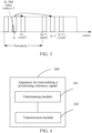
- FIG. 1 is a structural diagram of a wireless communication system to which the embodiments of this application are applicable.
- the wireless communication system includes a terminal 11 and a network side device 12.
- the terminal 11 may also be referred to as a terminal or a user terminal (User Equipment, UE).
- UE User Equipment
- the terminal 11 may be a terminal side device such as a mobile phone, a tablet computer (Tablet Computer), a laptop computer (Laptop Computer) or referred to as a notebook computer, a personal digital assistant (Personal Digital Assistant, PDA), a palm computer, a netbook, an ultra-mobile personal computer (ultra-mobile personal computer, UMPC), a mobile Internet device (Mobile Internet Device, MID), a wearable device (Wearable Device) or in-vehicle equipment (VUE), or a pedestrian terminal (PUE).
- the wearable device includes: a bracelet, a headphone, glasses, or the like. It should be noted that, a specific type of the terminal 11 is not limited in the embodiments of this application.
- the network side device 12 may be a base station or a core network, where the base station may be referred to as a NodeB, an evolved nodeB, an access point, a base transceiver station (Base Transceiver Station, BTS), a radio base station, a radio transceiver, a basic service set (Basic Service Set, BSS), an extended service set (Extended Service Set, ESS), a nodeB, an evolved nodeB (eNB), a home nodeB, a home evolved nodeB, a WLAN access point, a WiFi node, a transmitting receiving point (Transmitting Receiving Point, TRP), or another appropriate term in the field, as long as the same technical effect is achieved.
- the base station is not limited to a specific technical term. It should be noted that, a base station in the NR system is used as an example in the embodiments of this application, but a specific type of the base station is not limited.
- FIG. 2 is a flowchart of a method for transmitting a reference signal according to an embodiment of this application.
- the method for transmitting a reference signal includes the following steps.
- Step 201 A terminal determines a target transmission resource for transmitting a sidelink (SideLink, SL) reference signal, where the SL reference signal includes a reference signal for positioning.
- Sidelink Sidelink
- the SL reference signal may include: SL positioning reference signals (Positioning Reference Signals, PRSs) and other SL reference signals.
- the other SL reference signals are extended for positioning, for example, an SL synchronization signal block (SL Synchronization Signal Block, S-SSB), an SL channel state information reference signal (CSI reference signals, CSI-RS), an SL phase-tracking reference signal (Phase-tracking reference signal, PTRS), or an SL demodulation reference signal (Demodulation Reference Signal, DMRS).
- the SL reference signal in this application refers to a reference signal used for positioning, and does not only refer to an SL PRS.
- the SL PRS appearing in the following description is only used for illustration and is not limited to only the SL PRS. For solutions applicable to the SL PRS, other SL reference signals for positioning are all applicable.
- the target transmission resource may include a candidate resource or a reserved resource.
- Step 202 The terminal transmits the SL reference signal through the target transmission resource.
- the transmission of the SL reference signal may include sending or receiving the SL reference signal.
- the terminal determines the target transmission resource for transmitting the sidelink reference signal, and transmits the SL reference signal through the target transmission resource, to meet a requirement of positioning using the SL reference signal.
- the target transmission resource includes at least one of the following:
- the SL reference signal may be configured or indicated as periodic, semi-static, or aperiodic transmission.
- the target transmission resource for transmitting the SL reference signal is a periodic resource, or a semi-static resource, or an aperiodic resource.
- a periodicity value for periodic transmission is configured or indicated; if the SL reference signal is configured or indicated as semi-static transmission, downlink control information (Downlink Control Information, DCI) or sidelink control information (Sidelink Control Information, SCI) triggers a configured resource to be enabled or disabled; or if the SL reference signal is configured or indicated as aperiodic transmission, a location of the SL reference signal is preconfigured or configured.
- DCI Downlink Control Information
- SCI Sidelink Control Information
- An SL reference signal resource configured by the terminal or the another terminal may override an SL reference signal resource configured by the network side device (for example, configured through radio resource control (Radio Resource Control, RRC) signaling).
- RRC Radio Resource Control
- the terminal may select, from the candidate resource, a resource as a transmission resource for the SL reference signal.
- a target transmission resource configured by the terminal or the another terminal overrides a target transmission resource configured by the network side device; and/or, a target transmission resource indicated through a medium access control control element (Medium Access Control, MAC) control element (Control Element, CE) by the network side device, through DCI, or through SCI sent by the terminal overrides a target transmission resource configured through RRC.
- MAC Medium Access Control
- CE Control Element
- the MAC CE, the DCI, and the SCI may dynamically indicate the resource for transmitting the SL reference signal, that is, indicate the target transmission resource, where the target transmission resource indicated through the MAC CE by the network side device, through the DCI, or through the SCI sent by the terminal overrides the target transmission resource configured through the RRC.
- the network side device configures at least one pattern of the target transmission resource for the terminal, a target pattern of the target transmission resource is indicated through a MAC CE sent by the network side device, indicated through DCI sent by the network side device, or indicated through SCI sent by the terminal, and the target pattern is a pattern in the at least one pattern.
- the network side device preconfigures or configures one or more patterns (for example, N patterns) of an SL PRS resource that can be used by the terminal, and the MAC CE, the DCI, or the SCI indicates an SL PRS resource pattern used by UE.
- N patterns for example, N patterns
- the MAC CE, the DCI, or the SCI indicates an SL PRS resource pattern used by UE.
- Available PRS patterns are configured through RRC, and specific patterns are dynamically indicated.
- a number N of preconfigured or configured SL PRS resource patterns is equal to 1, a field value in the DCI or the SCI is 0.
- the field value in the DCI or the SCI is log2(N) bits.
- the target transmission resource is determined according to predefining and/or sensing.
- the first mapping relationship and the second mapping relationship may be determined through predefining, preconfiguring, and configuring.
- a mapping relationship between an SL PRS resource and a reserved resource of the PSFCH is predefined.
- the SL PRS is located on a symbol that the PSFCH is on, and mapping is started from next PRB of a highest PRB of the PSFCH, or mapping is started from next subchannel of a subchannel that the highest PRB of the PSFCH is in.
- a mapping relationship between the SL PRS resource and a reserved resource of the PSSCH/PSCCH is preconfigured.
- the SL PRS is located after at least N1 symbols after the PSSCH/PSCCH, and a frequency domain resource of the SL PRS is the same as a frequency domain resource of the PSSCH/PSCCH.
- the target transmission resource is determined according to at least one of sensing, the first mapping relationship, and the second mapping relationship.
- the UE determines a resource location of the SL PRS according to a resource location of the PSSCH/PSCCH determined through sensing and the mapping relationship between the SL PRS resource and the reserved resource of the PSSCH/PSCCH; or
- the UE determines a resource location of the SL PRS according to sensing information, a determined resource location of the PSFCH, and the mapping relationship between the SL PRS resource and the reserved resource of the PSFCH.
- the target transmission resource meets at least one of the following:
- a lowest subchannel (subchannel) of the PSFCH of the candidate resource may be selected as the start location of the SL reference signal, or a lowest PRB corresponding to the lowest subchannel of the candidate resource may be selected as the start location of the SL reference signal, or a highest subchannel of the candidate resource may be selected as the end location of the SL reference signal, or a highest PRB corresponding to the highest subchannel of the candidate resource may be selected as the end location of the SL reference signal.
- a PSFCH is enabled. Further, a time domain location of the enabled PSFCH is a candidate resource time domain location of the target transmission resource.
- a time domain location for enabling the configuring for the PSFCH in the resource pool is a candidate resource time domain location of the PRS.
- the configuring for the PSFCH is enabled, but transmission of the PSFCH is not enabled.
- a time domain resource location of the PSFCH is used for transmission of the SL reference signal rather than the transmission of the PSFCH.
- a time domain resource unit in this application may be a symbol, a slot, a subframe, ms, s, or the like. For different cases, time domain units may be different, which is not limited in this application.
- the PSFCH is configured in the resource pool, but a bandwidth of the SL reference signal is not limited in the resource pool. This emphasizes that the SL reference signal is in a time domain resource unit of the PSFCH.
- the target transmission resource is determined according to at least one of the following:
- one or more periodicity values are predefined, preconfigured, configured, or indicated. If the periodicity value is obtained according to SCI, a periodicity in a sidelink control information (Sidelink control information, SCI) format 1-A or a periodicity value of data may be read as a periodicity of the PRS, or the SCI independently indicates a periodicity value of the PRS, which is not limited thereto.
- SCI sidelink control information
- UE transmits the SL reference signal according to a time domain and/or frequency domain indication (TRI), in other words, the UE transmits the SL reference signal in an aperiodic transmission manner.
- TRI time domain and/or frequency domain indication
- the SL reference signal resource is determined according to a time domain indication and/or a frequency domain indication, or transmission of the SL reference signal resource is aperiodic transmission.
- the periodicity value of the SL reference signal resource is determined according to at least one of the following:
- the periodicity value of the SL reference signal resource is related to the priority of the SL reference signal, the QoS, the delay, the CBR, the CR, the RSRP, and the like.
- the periodicity value is a first periodicity; and if the CBR is less than the CBR threshold, the periodicity value is a second periodicity. (A more congested resource pool indicates that the resource allocated to the SL reference signal may be appropriately reduced, and an SL reference signal periodicity increases.)
- the periodicity value is the first periodicity; and if the delay is less than the delay threshold, the periodicity value is the second periodicity. (A shorter delay indicates that the resource needs to be sent as soon as possible, so that a sending periodicity is shorter.)
- the periodicity value is the first periodicity; and if the priority is greater than the priority threshold, the periodicity value is the second periodicity.
- the periodicity value defined above may refer to a periodicity value of one PRS resource (PRS resource), or may refer to a periodicity value of a PRS resource set (PRS resource set).
- the time interval of the SL reference signal resource meets at least one of the following:
- the time interval is the interval from the previously reserved SL reference signal resource, that is, a time interval from previous SL reference signal sending.
- UE 1 sends a PRS 1 and a PRS 2, where the PRS 1 is sent twice; and the PRS 2 is sent twice.
- Sending timing of the UE 1 is sequentially: a first PRS 1, a first PRS 2, a second PRS 1, and a second PRS 2.
- a previously reserved SL PRS resource is a resource for transmitting a same SL PRS (that is, a repetition interval, which is a same PRS by using UE as a unit) as an SL PRS resource.
- the first PRS 1 and the second PRS 1 is a same SL PRS, or the first PRS 2 and the second PRS 2 are a same SL PRS.
- the previously reserved SL PRS resource is a resource used by the UE to previously transmit an SL PRS (differentiated by using UE as a unit, and may be a same PRS or a different PRS, without limitation). For example, for an interval between a resource for sending the first PRS 1 and a resource for sending the first PRS 2, it is not limited whether the PRSs sent by the two resources are the same.
- the time interval is an interval between a reserved SL PRS resource and an SL PRS resource sent for the first time, that is, a time unit for an initial SL PRS to send SCI.
- a reserved SL PRS and an SL PRS sent for the first time are a same SL PRS (that is, repetition) or different SL PRSs, which are not limited thereto. For example, an interval between the first PRS 1 and the first PRS 2, an interval between the first PRS 1 and the second PRS 1, and an interval between the first PRS 1 and the second PRS 2.
- the target transmission resource may be determined according to the number of times of transmission or the index of the SL reference signal.
- the UE excludes a corresponding resource according to the index of the SL reference signal. For example, if SL PRS resource reservation indicates that three resources are reserved for an SL PRS, and an SL PRS index indicates second reservation, in a periodicity, the UE excludes, according to a field value, a time domain resource that the SL PRS is in and an SL PRS resource corresponding to next interval of the SL PRS; and when excluding a periodic resource, the UE excludes, according to the field value, a periodic resource corresponding to the SL PRS, a periodic resource corresponding to the SL PRS resource of the next interval of the SL PRS, and a periodic resource corresponding to an SL PRS resource of a previous interval of the SL PRS.
- a size of an indication field indicated by the MAC CE/DCI/SCI is log2(N)bits, where N is a predefined, preconfigured, or configured value.
- a parameter of the sensing or measuring window of the SL reference signal includes at least one of the following:
- the frequency domain resource bandwidth of the SL reference signal meets at least one of the following:
- the target transmission resource may be determined according to the resource pool identifier. If the target transmission resource is limited in a resource pool range, it may be similar to that sending of data of TX (sending) UE is limited in the resource pool range, which is equivalent to a TX resource pool. If the UE receives information, the UE determines a corresponding time domain or frequency domain resource range according to a configuration in the SL resource pool and the resource pool ID.
- the target transmission resource may be determined according to the repetition factor.
- the repetition factor may be a number of times of repeated transmission of the SL PRS, or a number of reserved resources.
- the target transmission resource may be determined according to the identifier parameter (ID parameter).
- ID parameter includes at least one of the following: (selection may be performed through a modulo operation based on the ID, or selection may be performed based on sensing (sensing) and the ID)
- the group identifier includes two types: the group ID, indicating a group number of a group; and the member ID, indicating a member ID number in the group, to identify numbers of different UE in the group ID.
- the priority of the SL reference signal meets at least one of the following:
- the target transmission resource is determined according to a sensing result, and when a resource determined through the sensing result meets a first condition, the resource determined through the sensing result is excluded, where the first condition includes at least one of the following:
- the UE performs sensing in a preset resource or resource pool, and when a resource meets at least one of the following conditions, the resource is excluded:
- the resource is excluded.
- An SL PRS may be determined according to the SCI.
- the RSRP threshold is a value that is predefined in a protocol, preconfigured, configured, or indicated.
- a priority value of the SL PRS is predefined as 1.
- the RSRP threshold is a value determined according to a priority mapping rule.
- the priority offset may be an integer.
- the priority of the SL PRS is greater than the SL priority. In an SL, a smaller priority value indicates a higher priority.
- the RSRP threshold is a value determined according to a data priority and an RSRP offset (offset).
- a first RSRP threshold is determined according to SL data, and the RSRP threshold is the first RSRP threshold plus the RSRP offset.
- the RSRP offset is a predefined, preconfigured, configured, or indicated value.
- the RSRP offset or the priority offset is related to the CR, the CBR, a number of ACKs, a number of NACKs, or the like.
- a resource in a corresponding time domain unit is excluded.
- the preset value or the preset ratio is a predefined, preconfigured, or configured parameter.
- An overlapping resource (an RE or a PRB or the like) in a corresponding time domain unit is excluded.
- remaining frequency domain resources in the time domain unit are optional.
- UE 1 needs to send an SL PRS 1. If an SL PRS 2 sent by another UE (e.g. UE 2) is sensed, the UE 1 senses and determines how many resources (REs/RBs/subchannels) remain in a time domain resource that the PRS 2 is in. If the resources are greater than a specified value, the UE 1 excludes the entire time domain resource; otherwise, resources occupied by the PRS 2 are excluded, and remaining resource are used as a reserved resource or a candidate resource of the PRS 1.
- SL PRS 2 sent by another UE e.g. UE 2
- the UE 1 senses and determines how many resources (REs/RBs/subchannels) remain in a time domain resource that the PRS 2 is in. If the resources are greater than a specified value, the UE 1 excludes the entire time domain resource; otherwise, resources occupied by the PRS 2 are excluded, and remaining resource are used as a reserved resource or a candidate resource of the PRS 1.
- the target transmission resource is determined according to a sensing result, and if a resource determined through the sensing result meets a second condition, the resource determined through the sensing result is selected, where the second condition includes at least one of the following:
- the UE performs sensing in a preset resource or resource pool, and if a resource meets the second condition, the resource is selected as a resource in a candidate resource set.
- the SL reference signal meets at least one of the following:
- the DCI or the SCI indicates an interval between an SL PRS of UE 2 (which can be understood as the terminal) and a (most recently) received SL PRS of UE 1 (which can be understood as a terminal communicating with the terminal).
- a minimum value of the resource interval is predefined, preconfigured, or configured (if transceiver conversion and SCI demodulation are considered).
- the SCI may be first stage SCI or second stage SCI. For that TX UE indicates RX (receiving) UE and the RX UE sends an SL PRS resource, the second stage SCI is more reliable.
- the first stage SCI indicates the TX UE to send an SL PRS resource.
- the DCI or the SCI indicates an interval between the SL PRS of the UE 2 and the received SCI.
- a minimum value of the resource interval is predefined, preconfigured, or configured.
- the SCI may be first stage SCI, second stage SCI, or standalone (standalone) SCI.
- Header UE or assisted UE may indicate a resource available for the RX UE. When the RX UE sends the SL PRS, refer to a location of the received SCI.
- a resource used by the terminal to send the SL reference signal and a resource used by another terminal to receive the SL reference signal have different bandwidths.
- the UE 1 sends the SL PRS in a bandwidth part (Bandwidth Part, BWP) range
- the UE 2 receives the SL PRS in a resource pool range.
- BWP Bandwidth Part
- the target transmission resource is determined according to the sensing or measuring window of the SL reference signal. In this case, at least one of the following is met:
- the cyclic shift is determined according to at least one of the following:
- the group identifier includes two types: the group ID, indicating a group number of a group; and the member ID, indicating a member ID number in the group, to identify numbers of different UE in the group ID.
- the "selection determining" may be that a transmit terminal selects, a scheduling terminal selects, or a receive terminal selects. If the "selection determining" is that another terminal selects, the terminal is notified through another signaling.
- the transmit power is determined according to at least one of the following:
- the terminal may adjust the transmit power according to the target pathloss, where the target pathloss includes at least one of the following:
- the SCI is first stage SCI or second stage SCI.
- a method for transmitting a reference signal provided in this application is described below by using an example.
- UE may send or receive an SL reference signal, to position UE performing transmission of the SL reference signal.
- an execution entity may be an apparatus for transmitting a reference signal, or a control module configured to execute and load the method for transmitting a reference signal in the apparatus for transmitting a reference signal.
- FIG. 4 is a structural diagram of an apparatus for transmitting a reference signal according to an embodiment of this application.
- An apparatus 300 for transmitting a reference signal includes:
- the target transmission resource includes at least one of the following:
- the target transmission resource is a periodic resource, or a semi-static resource, or an aperiodic resource.
- a target transmission resource configured by the terminal or the another terminal overrides a target transmission resource configured by the network side device; and/or a target transmission resource indicated through a medium access control control element MAC CE, downlink control information DCI, or sidelink control information SCI overrides a target transmission resource configured through radio resource control RRC.
- MAC CE medium access control control element
- DCI downlink control information
- SCI sidelink control information
- the network side device configures at least one pattern of the target transmission resource for the terminal, a target pattern of the target transmission resource is indicated through a MAC CE sent by the network side device, indicated through DCI sent by the network side device, or indicated through SCI sent by the terminal, and the target pattern is a pattern in the at least one pattern.
- the target transmission resource is determined according to predefining and/or sensing.
- the target transmission resource meets at least one of the following:
- a PSFCH is enabled.
- a time domain location of the enabled PSFCH is a candidate resource time domain location of the target transmission resource.
- the target transmission resource is determined according to at least one of sensing, the first mapping relationship, and the second mapping relationship.
- the target transmission resource is determined according to at least one of the following:
- the SL reference signal resource is determined according to a time domain indication and/or a frequency domain indication, or transmission of the SL reference signal resource is aperiodic transmission.
- the periodicity value of the SL reference signal resource is determined according to at least one of the following:
- the time interval of the SL reference signal resource meets at least one of the following:
- a parameter of the sensing or measuring window of the SL reference signal includes at least one of the following:
- the frequency domain resource bandwidth of the SL reference signal meets at least one of the following:
- the priority of the SL reference signal meets at least one of the following:
- the target transmission resource is determined according to a sensing result, and when a resource determined through the sensing result meets a first condition, the resource determined through the sensing result is excluded, where the first condition includes at least one of the following:
- the RSRP threshold is determined according to at least one of the following:
- the target transmission resource is determined according to a sensing result, and if a resource determined through the sensing result meets a second condition, the resource determined through the sensing result is selected, where the second condition includes at least one of the following:
- the SL reference signal meets at least one of the following:
- a resource used by the terminal to send the SL reference signal and a resource used by another terminal to receive the SL reference signal have different bandwidths.
- the target transmission resource is determined according to the sensing or measuring window of the SL reference signal; and correspondingly, the transmission module 302 is configured to sense or measure the SL reference signal in the sensing or measuring window of the SL reference signal.
- the target transmission resource is determined according to the sensing or measuring window of the SL reference signal, and the reference signal is in a range of the sensing or measuring window of the SL reference signal.
- the transmit power is determined according to at least one of the following:
- the target pathloss includes at least one of the following:
- the cyclic shift is determined according to at least one of the following:
- the SCI is first stage SCI or second stage SCI.
- the apparatus 300 for transmitting a reference signal in this embodiment of this application may be an apparatus, or may be a component, an integrated circuit, or a chip in a terminal.
- the apparatus 300 for transmitting a reference signal in this embodiment of this application may be an apparatus having an operating system.
- the operating system may be an Android (Android) operating system, may be an ios operating system, or may be another possible operating system, which is not specifically limited in this embodiment of this application.
- the apparatus 300 for transmitting a reference signal provided in this embodiment of this application can implement procedures implemented in the method embodiment of FIG. 2 , and can achieve the same technical effects. To avoid repetition, details are not described herein again.
- an embodiment of this application further provides a communication device 70, including a processor 71, a memory 72, and a program or instructions stored in the memory 72 and runnable on the processor 71.
- a communication device 70 including a processor 71, a memory 72, and a program or instructions stored in the memory 72 and runnable on the processor 71.
- the program or the instructions when executed by the processor 71, implement all processes of the embodiments of the method for transmitting a reference signal shown in FIG. 2 , and can achieve the same technical effects.
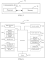
- FIG. 6 is a schematic diagram of a hardware structure of a terminal that implements the embodiments of this application.
- the terminal 1000 includes, but is not limited to, components such as a radio frequency unit 1001, a network module 1002, an audio output unit 1003, an input unit 1004, a sensor 1005, a display unit 1006, a user input unit 1007, an interface unit 1008, a memory 1009, and a processor 1010.
- components such as a radio frequency unit 1001, a network module 1002, an audio output unit 1003, an input unit 1004, a sensor 1005, a display unit 1006, a user input unit 1007, an interface unit 1008, a memory 1009, and a processor 1010.
- the terminal 1000 further includes a power supply (such as a battery) for supplying power to the components.
- the power supply may logically connect to the processor 1010 by using a power supply management system, thereby implementing functions, such as charging, discharging, and power consumption management, by using the power supply management system.
- a terminal structure shown in FIG. 6 does not constitute a limitation to the terminal, and the terminal may include more or fewer components than those shown in the figure, or some components may be combined, or a different component deployment may be used. Details are not described herein again.
- the input unit 1004 may include a graphics processing unit (Graphics Processing Unit, GPU) 10041 and a microphone 10042.
- the graphics processing unit 10041 processes image data of a still picture or a video obtained by an image capture apparatus (such as a camera) in a video capture mode or an image capture mode.
- the display unit 1006 may include a display panel 10061, for example, the display panel 10061 may be configured in a form such as a liquid crystal display or an organic light-emitting diode.
- the user input unit 1007 includes a touch panel 10071 and another input device 10072.
- the touch panel 10071 is also referred to as a touchscreen.
- the touch panel 10071 may include a touch detection apparatus and a touch controller.
- the another input device 10072 may include, but is not limited to, a physical keyboard, a function key (such as a volume control key, a switch key, or the like), a trackball, a mouse, and an operating lever, which is not described in detail herein.
- the radio frequency unit 1001 receives downlink data from a network side device and sends downlink data to the processor 1010 for processing. In addition, the radio frequency unit transmits uplink data to the base station.
- the radio frequency unit 1001 includes, but is not limited to, an antenna, at least one amplifier, a transceiver, a coupler, a low noise amplifier, a duplexer, and the like.
- the memory 1009 may be configured to store a software program or instruction and various data.
- the memory 1009 may mainly include a program or instruction storage region and a data storage region.
- the program or instruction storage region may store an operating system, an application program or instruction required by at least one function (for example, a sound playback function and an image playback function), or the like.
- the memory 1009 may include a high speed random access memory, and may also include a non-volatile memory.
- the nonvolatile memory may be a read-only memory (read-only memory, ROM), a programmable read-only memory (Programmable ROM, PROM), an erasable programmable read-only memory (Erasable PROM, EPROM), an electrically erasable programmable read-only memory (Electrically EPROM, EEPROM), or a flash memory.
- the non-volatile memory may be at least one magnetic disk storage device, a flash storage device, or other volatile solid-state storage devices.
- the processor 1010 may include one or more processing units.
- the processor 1010 may integrate an application processor and a modem.
- the application processor mainly processes an operating system, a user interface, an application program or instructions, and the like.
- the modem mainly processes wireless communication, such as a baseband processor. It may be understood that, the foregoing modem may not be integrated into the processor 1010.
- the processor 1010 is configured to determine a target transmission resource for transmitting a sidelink SL reference signal, where the SL reference signal includes a reference signal for positioning;
- the radio frequency unit 1001 is configured to transmit the SL reference signal through the target transmission resource.
- the target transmission resource includes at least one of the following:
- the target transmission resource is a periodic resource, or a semi-static resource, or an aperiodic resource.
- a target transmission resource configured by the terminal or the another terminal overrides a target transmission resource configured by the network side device; and/or a target transmission resource indicated through a medium access control control element MAC CE, downlink control information DCI, or sidelink control information SCI overrides a target transmission resource configured through radio resource control RRC.
- MAC CE medium access control control element
- DCI downlink control information
- SCI sidelink control information
- the network side device configures at least one pattern of the target transmission resource for the terminal, a target pattern of the target transmission resource is indicated through a MAC CE sent by the network side device, indicated through DCI sent by the network side device, or indicated through SCI sent by the terminal, and the target pattern is a pattern in the at least one pattern.
- the target transmission resource is determined according to predefining and/or sensing.
- the target transmission resource meets at least one of the following:
- a PSFCH is enabled.
- a time domain location of the enabled PSFCH is a candidate resource time domain location of the target transmission resource.
- the target transmission resource is determined according to at least one of sensing, the first mapping relationship, and the second mapping relationship.
- the target transmission resource is determined according to at least one of the following:
- the SL reference signal resource is determined according to a time domain indication and/or a frequency domain indication, or transmission of the SL reference signal resource is aperiodic transmission.
- the periodicity value of the SL reference signal resource is determined according to at least one of the following:
- the time interval of the SL reference signal resource meets at least one of the following:
- a parameter of the sensing or measuring window of the SL reference signal includes at least one of the following:
- the frequency domain resource bandwidth of the SL reference signal meets at least one of the following:
- the priority of the SL reference signal meets at least one of the following:
- the target transmission resource is determined according to a sensing result, and when a resource determined through the sensing result meets a first condition, the resource determined through the sensing result is excluded, where the first condition includes at least one of the following:
- the RSRP threshold is determined according to at least one of the following:
- the target transmission resource is determined according to a sensing result, and if a resource determined through the sensing result meets a second condition, the resource determined through the sensing result is selected, where the second condition includes at least one of the following:
- the SL reference signal meets at least one of the following:
- a resource used by the terminal to send the SL reference signal and a resource used by another terminal to receive the SL reference signal have different bandwidths.
- the target transmission resource is determined according to the sensing or measuring window of the SL reference signal; and correspondingly, the radio frequency unit 1001 is configured to sense or measure the SL reference signal in the sensing or measuring window of the SL reference signal.
- the target transmission resource is determined according to the sensing or measuring window of the SL reference signal, and the reference signal is in a range of the sensing or measuring window of the SL reference signal.
- the transmit power is determined according to at least one of the following:
- the target pathloss includes at least one of the following:
- the cyclic shift is determined according to at least one of the following:
- the SCI is first stage SCI or second stage SCI.
- the terminal 1000 provided in this embodiment of this application can implement all processes implemented by the embodiments of the method of FIG. 2 , and achieve technical effects. To avoid repetition, details are not described herein again.
- An embodiment of this application further provides a readable storage medium, storing a program or instructions.
- the program or the instructions when executed by a processor, implement all processes of the embodiments of the method shown in FIG. 2 , and can achieve the same technical effects. To avoid repetition, details are not described herein again.
- the processor is the processor in the terminal or the network side device in the foregoing embodiments.
- the readable storage medium includes a computer-readable storage medium, for example, a computer read-only memory (Read-Only Memory, ROM), a random access memory (Random Access Memory, RAM), a magnetic disk, or an optical disc.
- An embodiment of this application further provides a chip, including: a processor and a communication interface, where the communication interface is coupled to the processor, and the processor is configured to run a program or instructions of a network side device, to implement all processes of the embodiments of the method shown in FIG. 2 , and can achieve the same technical effects. To avoid repetition, details are not described herein again.
- the chip mentioned in this embodiment of this application may also be referred to as a system-level chip, a system chip, a chip system, a system on chip, or the like.
- the term “include”, “comprise” or any other variation thereof in this specification is intended to cover a non-exclusive inclusion, which specifies the presence of stated processes, methods, objects, or apparatuses, but does not preclude the presence or addition of one or more other processes, methods, objects, or apparatuses. Without more limitations, elements defined by the sentence “including one " does not exclude that there are still other same elements in the processes, methods, objects, or apparatuses.
- the scope of the methods and apparatuses in the implementations of this application is not limited to performing the functions in the order shown or discussed, but may also include performing, according to involved functions, the functions basically simultaneously or in a reverse order. For example, the described methods may be performed in an order different from that described, and various steps may also be added, omitted, or combined.
- features described with reference to some examples may be combined in other examples.
- the computer software product is stored in a storage medium (for example, a read-only memory (ROM)/random access memory (RAM), a magnetic disk or an optical disc), and includes several instructions for instructing a terminal (which may be a mobile phone, a computer, a server, an air conditioner, a network, or the like) to perform the method described in the embodiments of this application.
- a storage medium for example, a read-only memory (ROM)/random access memory (RAM), a magnetic disk or an optical disc
- a terminal which may be a mobile phone, a computer, a server, an air conditioner, a network, or the like
Landscapes
- Engineering & Computer Science (AREA)
- Signal Processing (AREA)
- Computer Networks & Wireless Communication (AREA)
- Mobile Radio Communication Systems (AREA)
Applications Claiming Priority (2)
| Application Number | Priority Date | Filing Date | Title |
|---|---|---|---|
| CN202111124386.3A CN115866741B (zh) | 2021-09-24 | 2021-09-24 | 参考信号的传输方法、装置及相关设备 |
| PCT/CN2022/120788 WO2023046053A1 (zh) | 2021-09-24 | 2022-09-23 | 参考信号的传输方法、装置及相关设备 |
Publications (2)
| Publication Number | Publication Date |
|---|---|
| EP4408098A1 true EP4408098A1 (de) | 2024-07-31 |
| EP4408098A4 EP4408098A4 (de) | 2025-05-14 |
Family
ID=85653151
Family Applications (1)
| Application Number | Title | Priority Date | Filing Date |
|---|---|---|---|
| EP22872097.5A Pending EP4408098A4 (de) | 2021-09-24 | 2022-09-23 | Referenzsignalübertragungsverfahren und -vorrichtung sowie zugehörige vorrichtung |
Country Status (4)
| Country | Link |
|---|---|
| US (1) | US20240235764A1 (de) |
| EP (1) | EP4408098A4 (de) |
| CN (1) | CN115866741B (de) |
| WO (1) | WO2023046053A1 (de) |
Cited By (1)
| Publication number | Priority date | Publication date | Assignee | Title |
|---|---|---|---|---|
| EP4413796A4 (de) * | 2022-03-31 | 2024-12-04 | ZTE Corporation | Positionierung von referenzsignalpriorität und nullleistungssignalen in sidelink |
Families Citing this family (21)
| Publication number | Priority date | Publication date | Assignee | Title |
|---|---|---|---|---|
| CN117014945A (zh) * | 2022-04-28 | 2023-11-07 | 维沃移动通信有限公司 | 功率确定方法、终端及可读存储介质 |
| GB2627284A (en) * | 2023-02-17 | 2024-08-21 | Nokia Technologies Oy | Method, apparatus and computer program |
| CN120814203A (zh) * | 2023-04-05 | 2025-10-17 | 高通股份有限公司 | 旁路定位参考信号的梳状偏移指示 |
| WO2024207369A1 (zh) * | 2023-04-06 | 2024-10-10 | 北京小米移动软件有限公司 | Sl prs的资源确定方法、装置、设备及存储介质 |
| CN118784171A (zh) * | 2023-04-06 | 2024-10-15 | 大唐移动通信设备有限公司 | Sl-prs资源请求方法、设备、装置及存储介质 |
| CN118843184B (zh) * | 2023-04-23 | 2025-06-10 | 上海星思半导体有限责任公司 | 侧链路资源池的配置方法、网络设备、终端及存储介质 |
| CN120826953A (zh) * | 2023-05-12 | 2025-10-21 | Oppo广东移动通信有限公司 | 无线通信的方法及终端设备 |
| CN118972003A (zh) * | 2023-05-15 | 2024-11-15 | 大唐移动通信设备有限公司 | 一种信息处理方法、装置及设备 |
| CN118972945A (zh) * | 2023-05-15 | 2024-11-15 | 大唐移动通信设备有限公司 | 用于直通链路定位的资源分配方法、设备及装置 |
| CN118972965A (zh) * | 2023-05-15 | 2024-11-15 | 大唐移动通信设备有限公司 | 发送参数的调整方法、通信设备、装置及存储介质 |
| WO2025000286A1 (zh) * | 2023-06-28 | 2025-01-02 | 北京小米移动软件有限公司 | 资源确定方法、信号接收方法、终端及通信系统 |
| CN119276442A (zh) * | 2023-07-04 | 2025-01-07 | 华为技术有限公司 | 通信方法和通信装置 |
| CN119383744A (zh) * | 2023-07-27 | 2025-01-28 | 维沃移动通信有限公司 | 资源确定方法、装置、网络侧设备及终端设备 |
| CN120935827A (zh) * | 2023-08-10 | 2025-11-11 | Oppo广东移动通信有限公司 | 资源选择方法和终端设备 |
| CN119485738A (zh) * | 2023-08-10 | 2025-02-18 | 大唐移动通信设备有限公司 | 信息传输方法、装置、设备及介质 |
| CN119519911A (zh) * | 2023-08-24 | 2025-02-25 | 维沃移动通信有限公司 | 旁链路定位参考信号的传输方法、终端及网络侧设备 |
| CN120188499A (zh) * | 2023-08-29 | 2025-06-20 | 北京小米移动软件有限公司 | 定位方法、装置、设备及存储介质 |
| WO2025065614A1 (zh) * | 2023-09-28 | 2025-04-03 | 北京小米移动软件有限公司 | 信道忙率测量方法、终端、通信设备和存储介质 |
| CN119893583A (zh) * | 2023-10-25 | 2025-04-25 | 华为技术有限公司 | 侧行链路上信息传输的方法和通信装置 |
| CN119946879A (zh) * | 2023-11-03 | 2025-05-06 | 华为技术有限公司 | 一种通信方法及其装置 |
| WO2025102326A1 (zh) * | 2023-11-16 | 2025-05-22 | 北京小米移动软件有限公司 | 信号发送、接收方法、终端、通信系统和存储介质 |
Family Cites Families (17)
| Publication number | Priority date | Publication date | Assignee | Title |
|---|---|---|---|---|
| US20160095092A1 (en) * | 2014-09-25 | 2016-03-31 | Intel Corporation | Resource allocation and use for device-to-device assisted positioning in wireless cellular technologies |
| EP3516911B1 (de) * | 2016-10-10 | 2021-05-19 | Huawei Technologies Co., Ltd. | Kommunikationsknoten und verfahren zur implementierung eines positionsbezogenen signalisierungsaustausches |
| US11317415B2 (en) * | 2017-08-17 | 2022-04-26 | Apple Inc. | Selecting resources for sidelink communication based on geo-location information |
| KR20200116950A (ko) * | 2018-02-06 | 2020-10-13 | 광동 오포 모바일 텔레커뮤니케이션즈 코포레이션 리미티드 | 사용자 디바이스 및 사용자 디바이스 사이의 측위 신호의 송수신 방법 |
| EP3821658A1 (de) * | 2018-08-09 | 2021-05-19 | Convida Wireless, Llc | Ressourcenverwaltung für 5g ev2x |
| US12127155B2 (en) * | 2019-08-15 | 2024-10-22 | Interdigital Patent Holdings, Inc. | WTRU assisted positioning |
| CN112583553B (zh) * | 2019-09-29 | 2022-02-08 | 大唐移动通信设备有限公司 | 信号传输方法及装置 |
| CN115632750A (zh) * | 2019-12-17 | 2023-01-20 | 大唐移动通信设备有限公司 | 一种直通链路定位参考信号的发送、接收方法及终端 |
| CN113055136B (zh) * | 2019-12-26 | 2022-08-30 | 大唐移动通信设备有限公司 | 一种定位参考信号的传输资源的配置、接收方法及终端 |
| US11985695B2 (en) * | 2020-02-23 | 2024-05-14 | Qualcomm Incorporated | Generating coordination information for sidelink communications |
| WO2021243580A1 (zh) * | 2020-06-02 | 2021-12-09 | 北京小米移动软件有限公司 | 下行定位参考信号传输方法、装置及存储介质 |
| WO2022180597A2 (en) * | 2021-02-25 | 2022-09-01 | Lenovo (Singapore) Pte. Ltd. | Sidelink ranging for positioning reference signal types |
| US12155591B2 (en) * | 2021-06-04 | 2024-11-26 | Qualcomm Incorporated | Reservation based sidelink reference signal transmission for positioning |
| CN117480825A (zh) * | 2021-06-22 | 2024-01-30 | 高通股份有限公司 | 用户设备发起的侧链路定位资源配置的选择 |
| CN115706627B (zh) * | 2021-08-02 | 2025-01-24 | 中信科智联科技有限公司 | 直通链路定位参考信号的发送方法、接收方法及装置 |
| US11832253B2 (en) * | 2021-08-13 | 2023-11-28 | Qualcomm Incorporated | Techniques for sidelink sensing and positioning |
| US12193035B2 (en) * | 2021-09-22 | 2025-01-07 | Qualcomm Incorporated | Multiplexing sidelink positioning reference signal resources |
-
2021
- 2021-09-24 CN CN202111124386.3A patent/CN115866741B/zh active Active
-
2022
- 2022-09-23 EP EP22872097.5A patent/EP4408098A4/de active Pending
- 2022-09-23 WO PCT/CN2022/120788 patent/WO2023046053A1/zh not_active Ceased
-
2024
- 2024-03-25 US US18/614,781 patent/US20240235764A1/en active Pending
Cited By (1)
| Publication number | Priority date | Publication date | Assignee | Title |
|---|---|---|---|---|
| EP4413796A4 (de) * | 2022-03-31 | 2024-12-04 | ZTE Corporation | Positionierung von referenzsignalpriorität und nullleistungssignalen in sidelink |
Also Published As
| Publication number | Publication date |
|---|---|
| WO2023046053A1 (zh) | 2023-03-30 |
| CN115866741B (zh) | 2026-02-03 |
| US20240235764A1 (en) | 2024-07-11 |
| EP4408098A4 (de) | 2025-05-14 |
| CN115866741A (zh) | 2023-03-28 |
Similar Documents
| Publication | Publication Date | Title |
|---|---|---|
| EP4408098A1 (de) | Referenzsignalübertragungsverfahren und -vorrichtung sowie zugehörige vorrichtung | |
| JP7575583B2 (ja) | パワー制御方法、装置及び端末機器 | |
| US9801198B2 (en) | Unlicensed frequency band with licensed frequency band timing | |
| CN102368871B (zh) | 一种pdcch资源的配置应用方法及装置 | |
| WO2020200171A1 (zh) | 通信方法及装置 | |
| CN115225218B (zh) | 旁链路反馈资源的确定方法、终端及网络侧设备 | |
| US12389377B2 (en) | Partial sensing method and device for device-to-device communication in wireless communication system | |
| WO2023011454A1 (zh) | 旁链路资源确定方法、装置、终端及存储介质 | |
| US10440701B2 (en) | User equipment and power allocation method | |
| EP4383777A1 (de) | Kanalzugriffsverfahren für sidelink-feedbackinformationen, kanalzugriffsverarbeitungsverfahren für sidelink-feedbackinformationen und zugehörige vorrichtung | |
| US10560979B2 (en) | Measurement result reporting method, method for counting by timer, apparatus, and user equipment | |
| JP7660698B2 (ja) | 上りリンク伝送方法、装置及び端末 | |
| EP4221450A1 (de) | Informationsübertragungsverfahren und -vorrichtung, ressourcenauswahlverfahren und -vorrichtung und elektronische vorrichtung | |
| CN115150925A (zh) | 非优选传输资源的有效信令 | |
| WO2017132964A1 (zh) | 一种上行数据传输方法及相关设备 | |
| EP4161191A1 (de) | Verfahren und vorrichtung zur wiederherstellung eines strahlausfalls und vorrichtung | |
| JP7657970B2 (ja) | 上りリンク伝送時間ウィンドウの決定方法、装置、端末及びネットワーク側機器 | |
| WO2023051524A1 (zh) | 物理旁链路反馈信道的传输方法及装置 | |
| CN111742573A (zh) | 用户设备发起的带宽请求 | |
| US20240114554A1 (en) | Method and Device for Determining Resource in Shared Band | |
| WO2022214071A1 (zh) | 信号传输方法、装置及终端 | |
| JP2025515151A (ja) | アップリンクチャネル割当への拡張されたアップリンク制御情報マッピング | |
| US20250048322A1 (en) | Sidelink positioning processing method and apparatus, terminal, and readable storage medium | |
| CN115189838A (zh) | 物理下行控制信道重复传输方法、装置及用户设备 | |
| EP4554301A1 (de) | Informationsverarbeitungsverfahren und -vorrichtung sowie endgerät |
Legal Events
| Date | Code | Title | Description |
|---|---|---|---|
| STAA | Information on the status of an ep patent application or granted ep patent |
Free format text: STATUS: THE INTERNATIONAL PUBLICATION HAS BEEN MADE |
|
| PUAI | Public reference made under article 153(3) epc to a published international application that has entered the european phase |
Free format text: ORIGINAL CODE: 0009012 |
|
| STAA | Information on the status of an ep patent application or granted ep patent |
Free format text: STATUS: REQUEST FOR EXAMINATION WAS MADE |
|
| 17P | Request for examination filed |
Effective date: 20240423 |
|
| AK | Designated contracting states |
Kind code of ref document: A1 Designated state(s): AL AT BE BG CH CY CZ DE DK EE ES FI FR GB GR HR HU IE IS IT LI LT LU LV MC MK MT NL NO PL PT RO RS SE SI SK SM TR |
|
| DAV | Request for validation of the european patent (deleted) | ||
| DAX | Request for extension of the european patent (deleted) | ||
| REG | Reference to a national code |
Ref country code: DE Ref legal event code: R079 Free format text: PREVIOUS MAIN CLASS: H04W0072040000 Ipc: H04L0005000000 |
|
| RIC1 | Information provided on ipc code assigned before grant |
Ipc: H04W 92/18 20090101ALN20250108BHEP Ipc: H04W 64/00 20090101ALN20250108BHEP Ipc: H04L 27/26 20060101ALN20250108BHEP Ipc: G01S 5/02 20100101ALN20250108BHEP Ipc: G01S 5/00 20060101ALN20250108BHEP Ipc: H04W 52/38 20090101ALI20250108BHEP Ipc: H04W 52/24 20090101ALI20250108BHEP Ipc: H04B 17/27 20150101ALI20250108BHEP Ipc: H04W 72/40 20230101ALI20250108BHEP Ipc: H04W 72/04 20230101ALI20250108BHEP Ipc: H04L 5/00 20060101AFI20250108BHEP |
|
| A4 | Supplementary search report drawn up and despatched |
Effective date: 20250415 |
|
| RIC1 | Information provided on ipc code assigned before grant |
Ipc: H04W 92/18 20090101ALN20250409BHEP Ipc: H04W 64/00 20090101ALN20250409BHEP Ipc: H04L 27/26 20060101ALN20250409BHEP Ipc: G01S 5/02 20100101ALN20250409BHEP Ipc: G01S 5/00 20060101ALN20250409BHEP Ipc: H04W 52/38 20090101ALI20250409BHEP Ipc: H04W 52/24 20090101ALI20250409BHEP Ipc: H04B 17/27 20150101ALI20250409BHEP Ipc: H04W 72/40 20230101ALI20250409BHEP Ipc: H04W 72/04 20230101ALI20250409BHEP Ipc: H04L 5/00 20060101AFI20250409BHEP |