EP4407897A1 - Übertragung einer nachricht durch quantenkommunikation mit abhörerkennung - Google Patents
Übertragung einer nachricht durch quantenkommunikation mit abhörerkennung Download PDFInfo
- Publication number
- EP4407897A1 EP4407897A1 EP24154028.5A EP24154028A EP4407897A1 EP 4407897 A1 EP4407897 A1 EP 4407897A1 EP 24154028 A EP24154028 A EP 24154028A EP 4407897 A1 EP4407897 A1 EP 4407897A1
- Authority
- EP
- European Patent Office
- Prior art keywords
- receiver
- photon
- photons
- polarization
- list
- Prior art date
- Legal status (The legal status is an assumption and is not a legal conclusion. Google has not performed a legal analysis and makes no representation as to the accuracy of the status listed.)
- Granted
Links
Images


Classifications
-
- H—ELECTRICITY
- H04—ELECTRIC COMMUNICATION TECHNIQUE
- H04B—TRANSMISSION
- H04B10/00—Transmission systems employing electromagnetic waves other than radio-waves, e.g. infrared, visible or ultraviolet light, or employing corpuscular radiation, e.g. quantum communication
- H04B10/70—Photonic quantum communication
-
- H—ELECTRICITY
- H04—ELECTRIC COMMUNICATION TECHNIQUE
- H04L—TRANSMISSION OF DIGITAL INFORMATION, e.g. TELEGRAPHIC COMMUNICATION
- H04L9/00—Cryptographic mechanisms or cryptographic arrangements for secret or secure communications; Network security protocols
- H04L9/08—Key distribution or management, e.g. generation, sharing or updating, of cryptographic keys or passwords
- H04L9/0816—Key establishment, i.e. cryptographic processes or cryptographic protocols whereby a shared secret becomes available to two or more parties, for subsequent use
- H04L9/0852—Quantum cryptography
-
- H—ELECTRICITY
- H04—ELECTRIC COMMUNICATION TECHNIQUE
- H04L—TRANSMISSION OF DIGITAL INFORMATION, e.g. TELEGRAPHIC COMMUNICATION
- H04L9/00—Cryptographic mechanisms or cryptographic arrangements for secret or secure communications; Network security protocols
- H04L9/08—Key distribution or management, e.g. generation, sharing or updating, of cryptographic keys or passwords
- H04L9/0861—Generation of secret information including derivation or calculation of cryptographic keys or passwords
- H04L9/0869—Generation of secret information including derivation or calculation of cryptographic keys or passwords involving random numbers or seeds
Definitions
- the present invention relates to methods of transmitting a message by quantum communication with eavesdropping detection, and more particularly methods of transmitting a message by quantum communication using entangled photons with eavesdropping detection by cryptography.
- Computers and electronic devices are often connected to a network, physically, wirelessly, by RFID, or other secure or insecure means, and sometimes need to be able to know the identity of the device that sent them certain data, e.g. to ensure that this data has not been transmitted by another device, which intercepted and modified it before sending it back to the legitimate recipient, or simply to identify beyond a shadow of a doubt the identity of the the sender of the data, which is for example a car on a road network or an RFID tag worn by a competitor during a sporting event, or a list of bits generated randomly by a Quantum Key Generating Device (QKD), or for any other reason why the identity of the sender of the data is important to the recipient.
- QKD Quantum Key Generating Device
- Quantum Key generating devices often use electronic signatures exchanged between two remote parties receiving a randomly generated key to ensure that the key received is the same for each party.
- advances in quantum computing and/or cryptography may make it possible to recover the keys used for the electronic signature of received keys, making it possible to share the supposedly secret key between a legitimate device and a non-legitimate device without the legitimate device notices this.
- Transmitted data can be sent fully encrypted using a key assigned to the sender.
- encrypting all data makes it difficult the use of single-use keys (block keys once). More specifically, 100% data encryption is a process that uses keys as long as the data they encrypt, and these keys must be renewed after use.
- MD5 and SHA1 are algorithms typically used for these hashing operations.
- data hashes are typically much smaller in size than the initial data, and it may be possible to create other data, similar to but slightly different from the initial data, whose hash is equal to the hash of the initial data. This data could therefore be substituted for the initial data, without it being rejected by the hash verification procedure. It is possible to substitute data of any type, but the user detectability of the substitution decreases as the complexity of the data increases (a long text, an audio file, a photo, or a video). To perform the substitution, it is not even necessary to decrypt the encrypted hash. Just calculate the hash of the initial data. Additionally, hash functions such as MD5 and SHA1 are hash functions that are currently relatively easy to bypass.
- Quantum computers under development should soon be able to bypass the security provided by hash functions, since they are able to optimize the starting files so that they have a predefined hash.
- the patent application CN101547184 uses a plurality of auxiliary authentication values that are exchanged between a server and users.
- the patent application EP 1 421 548 describes a method of transmitting information, in which a message to be sent is concatenated with a random number and then hashed. The hash result is sent unencrypted to the other party. The message is sometimes transmitted as is or encrypted. The random number is always transmitted signed, and optionally encrypted, to the other party. Failure to encrypt the hash when the message itself is not encrypted makes the transmission vulnerable to very powerful or quantum computers capable of calculating random numbers consistent with the unencrypted message and the result of the hash. Additionally, encrypting the entire message has the disadvantage, if such encryption uses block-once keys, which are supposed to be tamper-proof, of requiring that both corresponding parties have access to these shared keys.
- the transmission of information is currently mainly done using electromagnetic waves, whether they have small wavelengths, like light, or long wavelengths like VHF waves.
- the transmitted waves can be guided by metal cables, by optical fibers, or even transmitted through space.
- the value of a bit is arbitrarily assigned to a direction, or to a mode of polarization of the photon. Suites polarized photons can then be sent to transmit binary sequences composing a message.
- Entangled photons are photons whose quantum states, for example their polarization, depend on each other, whatever the distance separating them.
- the patent KR101003886B1 describes an encrypted information transmission system in which entangled photons are emitted simultaneously and each sent to two targets positioned at different locations and wishing to communicate with each other.
- the photons received by the two targets form entangled random sequences of conjugated bits, these sequences being used as cryptographic encryption keys.
- This system allows almost instantaneous reception in two different locations of the same sequence of random numbers but does not allow the transmission of information.
- the polarization of a photon is not necessarily binary like that of a spin or even quaternary. It can in particular be represented on the Jones sphere which characterizes the orientation and the ellipse of the polarization: a polarization can in fact be linear, the electric field always being parallel to an axis perpendicular to the direction of propagation of the photon, or circular, the electric field rotating around this axis, or between the two: the electric field traveling in an ellipse around the axis of propagation.
- the orientation measures the direction of this axis
- the eccentricity measures the flattening of the ellipse
- the aforementioned devices do not make it possible to exploit all polarization configurations and are in fact limited in the number and type of information that it is possible to transmit.
- the relative polarization of a photon can be the polarization of the photon.
- the relative polarization of a photon is a bit assigned to all possible polarizations that the second entangled photon can take after the first photon has reached the first receiver, where 1 is said bit assigned from an entangled photon to a photon to which a 0 has been assigned.
- the first secret number can be kept secret and used again.
- the first secret number can preferably be changed periodically, for example every time or every day.
- the second secret number may be kept secret and reused or, preferably, may be changed periodically, for example every time or every day.
- the first secret number may be a first renewable key, for example renewed after each use and/or the second secret number may be a second renewable key, for example renewed after each use.
- the first secret number is kept secret and reused, and the second secret number is a single-use key renewed after each use.
- the transmission and detection method is preferably not implemented if the first or second key is no longer secret.
- the receivers can share the secret numbers with each other before step (K) takes place.
- the secret numbers can be exchanged between the two receivers after step (K).
- Receivers can share the secret number by sending it to each other encrypted using a one-time key.
- a mixer number identifier may be exchanged between the first and second receivers, each of which is capable of retrieving the corresponding mixer number from a stored list of mixer numbers.
- the shuffle function may be an XOR logic function, or a suffix function, of adding the mixer number to the end of the sixth list, or an encryption function using the mixer number as the encryption key to encrypt the sixth list.
- the shuffle function may alternatively be a combination of an XOR function, a suffix function of adding the mixer number to the end of the first data set, and an encryption function using the mixer number as the encryption key to encrypt the first data set.
- the encryption function may be an XOR function.
- a signed message can be exchanged after step ix. between the two receivers before the sixth and seventh lists are used as one-time keys.
- the information deduction list I can be considered not to have been listened to if the two data compared in step ix. are equal.
- the lists established in step (G) can be established for the transmission of a single piece of information I.
- the lists established in step (G) can be established using photons transmitted for the transmission of a series of multiple information.
- the second propagation path is preferably physically protected against eavesdropping, at least for a portion of the second propagation path terminating at the second receiver, where the photons propagate from the transmitter after their entangled photon has been received by the first receiver.
- This portion is preferably long enough so that the difference between the travel time of a photon in said portion and the travel time of the photon in the non-entangled state towards the second receiver can be detected by the second receiver and that this detection allows the second receiver to mark any incoming message as potentially being listened to by a third party.
- Two polarization rotators are preferably placed in front of the two photon receivers, respectively, the two photon rotators changing the direction of polarization of the photons synchronously and randomly, for example by 45° or 0°, for example each photon or every second photon, so that a spy photon transmitter cannot know the polarization directions measured by the receivers.
- the two receivers can share a list of random bits, where 0 represents a 0° rotation and 1 represents a 45° rotation.
- the sixth list and the seventh list may consist of bits, and can potentially be used as a shared list of random bits.
- the transmitted message M can be used as an encryption key if the deduction list was considered not to have been listened to.
- the encryption keys generated during the transmission and detection process and/or consisting of the message M can be used if the deduction list was considered not to have been listened to, as first and/or second numbers secrets.
- the first receiver may encode the same I information on many successive incoming photons, since some of their entangled photons may be lost before reaching the second receiver.
- the first receiver can reserve information I 0 to be used to separate the sending of any two other pieces of information, in particular if these two other pieces of information are identical, representing for example the same letter.
- Step (F) consisting of deducing the transmitted message M from the deduction list, can be carried out by the first receiver having coded a separation letter between any two equal successive letters of the message M, taking into account the travel time t tra and the fifth list, removing from the deduction list the polarizations of photons for which the first entangled photon never reached the first receiver, in order to create an approved deduction list, and the second receiver deducing from the deduction list approved the message M having been transmitted.
- the second receiver can count as received information any information successively recorded on the deduction list more than a predefined number times within a predefined number of pieces of information I received successively. For example, if there are 450 different polarization state pairs that can be encoded on the photons and if the propagation paths lose 90% of the photons between the transmitter and receivers, the second receiver can count as being one information received any information appearing at least 6 times among the 200 photons received, or any information appearing at least 6 times among the 200 successive records of the deduction list.
- the pair of complementary absorption polarizations can be chosen from at least three different pairs of complementary absorption polarizations.
- the pair of complementary absorption polarizations may be selected from at least 210 distinct pairs of complementary absorption polarizations.
- a plurality of pairs of entangled photons can be generated successively by the transmitter, each pair of photons making it possible to transmit information from the first receiver to the second receiver.
- the complex absorber can be configured to absorb the photon in a predetermined polarization state selected from the states of at least three different pairs of complementary polarizations.
- the polarization modifier may include a polarization direction modifier disposed upstream of a polarization phase modifier.
- the polarization direction modifier may comprise two quarter-wave blades arranged one after the other on the propagation path of the first photon, the orientation of at least one of the two blades being variable.
- the polarization direction modifier may include a blade or prism made of chiral or rotating material inducing a rotation of the polarization by an angle depending on the location through which the wave enters said chiral or rotating material.
- the polarization phase modifier may comprise a first blade or a first birefringent prism dividing the beam into two electromagnetic waves of linear polarization, one along a first axis and the other along a second axis, and a blade with a delay of variable refractive index arranged on the second axis.
- Said at least one instrument may include at least one filter making it possible to send the first photon to one or the other of two photon detectors depending on the polarization state of the first photon.
- the measuring instrument of the second receiver may include at least one photon detector arranged to measure the polarization of the light resulting from the multiplication of the second photon.
- the measuring instrument of the second receiver may comprise a succession of semi-reflecting blades arranged downstream of the optical amplifier, said blades directing the flow of multiplied photons with equal intensity towards a first phase measuring instrument, the latter being a polarization measuring instrument arranged to measure the intensity of the flux along two perpendicular axes, a second phase measuring instrument measuring the phase shift of the light between these same two axes, and a third phase measuring instrument measuring the phase shift of light between the bisector of the same axes and an axis perpendicular to this bisector.
- the first semi-reflective blade can deflect one third of the light flux towards the first phase measuring instrument, and the second semi-reflective blade can deflect half of its incoming light flux to the second phase measuring instrument and the remaining half of its incoming light flux to the third phase measuring instrument.
- the optical amplifier may be a doped fiber amplifier.
- the transmitter may be configured to successively generate a plurality of pairs of entangled photons.
- the transmitter and each of the receivers may include a clock, the clocks of the transmitter and the receivers being synchronized with each other.
- the second receiver may include a switch disposed in front of the optical amplifier and configured to absorb or reflect the photon(s) subsequent to a first photon reaching said second receiver in a predetermined time interval.
- the first quantum communications system may include a second transmitter capable of generating one or more pairs of entangled photons, the second transmitter being located closer to the second receiver than the first receiver.
- the second variant of the system according to the invention is arranged to retransmit almost instantly a series of values, continuous or discrete, between two locations.
- the first and second photons being entangled, the absorption of the first photon at the first receptor instantly determines the polarization of the second photon, in particular before it reaches the second receptor.
- Measuring the average polarization of the photons multiplied at the second receiver then makes it possible to detect in which polarization state the first photon was absorbed and to deduce the transmitted information.
- This second variant of the system therefore makes it possible to transmit information without latency, regardless of the distance between the two places wishing to communicate, and using only photons, which requires little energy.
- the second variant of the system is for example used for communication networks and computer networks on Earth, in the sky and/or in space, in particular to communicate with systems distant from Earth, such as satellites or ships. space.
- complementary polarization states also referred to below as “complementary absorption polarization states”
- linear optical elements in particular mirrors, birefringent blades and/or prisms, including quarter-wave blades, allows for one its absorption by a first polarizing filter, and for the other its absorption by a second polarizing filter according to a polarization orthogonal to that according to which the first polarizing filter can absorb.
- polarization state and “polarization” are used interchangeably.
- the first receiver is advantageously arranged so that its user can select the polarization state in which the photon is absorbed from any of the possible polarizations as defined by the Jones formalism, in particular from a set of elliptical polarizations (also called "ellipsoidal") characterized by the orientation and the ellipse of the polarization.
- the complex absorber of the first receiver is configured to absorb the photon in a state of a predetermined pair of complementary polarizations, selected among the states of at least three different pairs of complementary polarizations, and preferably among a number of different pairs of complementary polarizations selected according to the number of different values to be transmitted, as described above.
- selected polarization is meant a pair of complementary polarizations predetermined according to the information to be transmitted.
- the linear polarization of a photon can be converted into ellipsoidal polarization as represented by the Jones formalism by firstly modifying the orientation of the polarization of a photon of linear polarization and known direction, thus distributing in a predetermined manner the electric field along an x axis and a y axis perpendicular to the x axis then, in a second step, by modifying the phase of the electric field along one of two perpendicular directions, for example the y axis.
- the polarization modifier preferably comprises a polarization direction modifier arranged upstream of a polarization phase modifier.
- E x E cos ⁇ cos ⁇ t
- E y E sin ⁇ cos ⁇ t
- a direction of linear polarization can be modified in different ways, for example by a half-wave plate or alternatively by a double quarter-wave plate.
- the polarization direction modifier may comprise two quarter-wave blades arranged one after the other on the propagation path of the first photon, the orientation of at least one of the two blades being variable.
- the first quarter-wave plate modifies, for example, the linear polarization into circular polarization and the second quarter-wave plate converts, for example, the circular polarization into a linear polarization whose direction is oriented along an axis depending on the direction of the axis of the second quarter-wave blade.
- a rotation of the axis of this second blade therefore makes it possible to modify the direction of the linear polarization of the photon.
- the plate is a half-wave plate, the rotation of this so-called half-wave plate makes it possible to modify the direction of the linear polarization of the photon.
- the rotation of a quarter-wave blade or a half-wave blade is obtained for example by mechanical control of a sensor or an electrically controlled device allowing its rotation, for example by rubbing on a shaft set in motion by a piezoelectric material or by an electric motor device, for example direct current.
- a plurality of linear polarization rotation devices can be used, each allowing different angles of rotation, for example fixed, but which can just as easily be modifiable, selectors making it possible to send the photons towards one of these rotation devices and, at the output of said rotation device, to conduct said photon towards a common waveguide or a common transmission axis.
- selectors can include a mirror whose direction of the axis is controlled for example by an electrical device, or alternatively made up of a prism or a blade made of a material whose refractive index depends on a field electrical: a Pockels cell, or a transparent material with a non-linear refractive index, another light flux, for example transverse and preferably of a wavelength different from that of the photon and not being able to generate photons having the same wavelength than that of the photon, varying the refractive index of said non-linear material and thus controlling the location and optionally the direction of exit of the photon from said material.
- an electrical device or alternatively made up of a prism or a blade made of a material whose refractive index depends on a field electrical: a Pockels cell, or a transparent material with a non-linear refractive index, another light flux, for example transverse and preferably of a wavelength different from that of the photon and not being able to generate photons having the same
- the rotational inertia of a quarter-wave plate can be significant, the photons can be sent successively to different quarter-wave plates whose direction will have been adjusted beforehand, for example by one of the mechanical rotation devices described above. , thus allowing time to modify the direction of each of these quarter-wave plates between two passages of photons.
- chiral or rotating materials can be used to modify a linear polarization direction.
- the polarization direction modifier may include a blade or prism made of chiral or rotating material inducing a rotation of the polarization by an angle depending on the location through which the wave enters said chiral or rotating material.
- the material can in particular be placed between two Pockels cells.
- the first photon can be projected onto a first plate or a first prism forming a Pockels cell whose refractive index is controlled by an electric field to emerge at different locations, in particular on an intermediate plate or prism made of material at less partly chiral or rotary rotating the axis of electrical polarization of the photon by an angle depending on the place through which the wave enters said plate or said intermediate prism, before penetrating into a second plate or a second prism forming a Pockels cell whose refractive index is adjusted symmetrically with respect to that of the first blade or the first prism to bring out the photon in the same direction as if the refractive indices of the first blade or prism and the second blade or prism both had a fixed value.
- a third blade whose refractive index can be adjusted, for example electrically, is advantageously placed after the second blade or prism to make it possible to render the location of the exit of the photon from the set of plates and prisms independent of the refractive index selected for the first plate or prism.
- the blade or prism made of intermediate material is for example composed of two adjacent symmetrical prisms of the same refractive index but having different chiral or rotating powers, the first of the two prisms having for example a chiral or rotating power and the second not having any. not or rotating the electric field in the opposite direction to the rotation imposed by the first prism.
- One of the two intermediate prisms may comprise a chiral material, for example cadmium selenide (CdSe) nanoparticles having a diameter of approximately 1.4 to 2.4 nm as described in the article by Visheratina, Anastasia, and Nicholas A. Kotov. "Inorganic nanostructures with strong chiroptical activity.” (CCS Chemistry 2.3 (2020): 583-604 .); the other intermediate prism preferably not being chiral or alternatively having the opposite chirality to that of said first intermediate prism.
- the rotation of the electric field of waves passing through a chiral material being proportional to the thickness passing through said chiral material, the rotation of the electric field passing through the intermediate plate depends on the location through which it is penetrated by the light passing through it.
- One of the two intermediate prisms may also include a "rotating" material, such as a superposition of an even number of quarter-wave plates stacked on top of each other in directions incremented at each layer by a predetermined angle. , so that a wave polarized linearly along the axis of the first slice of the material emerges from the stack with a polarization rotated by an angle proportional to the thickness of the stack.
- a rotating material such as a superposition of an even number of quarter-wave plates stacked on top of each other in directions incremented at each layer by a predetermined angle.
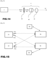
- a second device called a “polarization phase modifier” can be placed downstream of the polarization direction modifier, in order to phase shift the component of the electric field of the photon by a predetermined angle along one of two fixed axes.
- the polarization phase modifier comprises a first birefringent blade or prism arranged to divide the beam into two electromagnetic waves of linear polarization, one along a first axis, the other along a second axis, and a delay plate having a variable refractive index arranged on the second axis.
- the delay plate causes the wave oriented along the second axis to acquire a predetermined phase shift with respect to the wave oriented along the first axis, before being mixed with it again by a new plate or a new birefringent prism making it possible to reunite according to the same axis the two waves whose polarization fields are perpendicular.
- the delay plate may include a Pockels cell or a nonlinear material.
- the variable refractive index makes it possible to select the phase shift imposed on the wave oriented along the second axis.
- the phase modifier rotates a linear polarization of angles spaced by 9° varying between -45° and +36° and varies the phase of angles spaced by 9°. ° between -90° and +90°, thus defining 210 possible polarization states.
- 209 of the 210 possible polarizations are for example used to encode data and the 210th linear polarization is used to absorb any entangled photon received in a predetermined time after reception of a photon having been used to encode a given.
- the phase modifier rotates the polarization axis by 45° before the photon is absorbed to transmit for example a 0, and transforms the polarization of the photon into circular polarization to transmit for example a 1.
- observation base we designate a base of two complementary polarizations, for example two orthogonal linear polarizations.
- indeterminate polarization in an observable base we designate a photon whose polarization as observed in one of the two predetermined polarizations of an observable base is not defined, that is to say is random, for example in an equiprobable way.
- the first and second photons being entangled, the absorption of the first photon at the first receptor instantly determines the polarization of the second photon, in particular before it reaches the second receptor.
- Measuring the polarization of the photons multiplied at the second receiver then makes it possible to detect whether or not the first photon has been absorbed, and to deduce what information has been transmitted.
- the information transmitted by this third variant of the system is for example of binary type.
- the first receiver may include at least one second absorption instrument, the optical selector being arranged upstream of the first and second instruments and configured to either let the first photon pass by directing it towards one or the other of the instruments, or prevent it from being absorbed.
- the use of two instruments makes it possible to transmit three different pieces of information, for example the values 0, 1 and 2, the value 0 being for example assigned to the reflection, the value 1 to the first instrument, and the value 2 to the second instrument.
- the optical selector of the first receiver can be of varied type. It is advantageously placed upstream of the measuring instrument in order to be able to prevent the incident photon from reaching the measuring instrument, if this is desired.
- the selector preferably comprises a reflector, in particular a controlled mirror, making it possible for example to reflect the first photon on a propagation path different from its incident propagation path, in particular on a propagation path not including the instrument measurement.
- controlled mirror is meant a device whose certain properties, for example the refraction properties or the direction of reflection, are controlled by an additional device connected to the mirror, in particular an electronic device, for example generating an electric field.
- the optical selector preferably comprises a device whose refractive index and/or direction of reflection are controlled, in particular controlled using an electric field or a luminous flux.
- the optical selector comprises for example a Bragg mirror, in particular a Bragg mirror whose direction of reflection is controlled by a piezoelectric material, itself controlled by an electric field.
- the optical selector comprises a prism, in particular comprising Pockels cells whose refractive index is controlled by an electric field, the application of an electric field being able to direct the photon towards the or one of the instruments of measurement or towards a Bragg mirror advantageously inclined relative to the direction of incidence of the waves electromagnetic waves reaching it, so that said waves are reflected towards a location preferably different from that from which they come at the entrance to the prism.
- the optical selector comprises one or a succession of Bragg filters, certain layers of which are Pockels cells whose refractive index is controlled by an electric field, said Bragg filter reflecting or allowing the light wave to pass through. depending on the application or not of the electric field.
- the Pockels cells used above are replaced by non-linear crystals illuminated by powerful light capable of varying the refractive index of the medium crossed by the photon, the wavelength of the powerful light preferably being different of the wavelength of the photon.
- the optical selector makes it possible in particular to orient the photons in three different directions, one direction allowing for example the photons not to be detected, a second allowing a linear polarization of the photons to be measured and a third allowing a circular polarization to be measured.
- the quantum communication system further comprises a device for protecting the quantum state of at least one photon, in particular a device which prevents the measurement or absorption of at least one photon, arranged near the first receiver so as to make it possible to protect the quantum state of the first photon after its reflection, preventing it from being absorbed or measured by one or more measuring instruments, said quantum state of the first photon being protected at least until 'until the second photon has been multiplied at the second receiver.
- a device for protecting the quantum state of at least one photon in particular a device which prevents the measurement or absorption of at least one photon, arranged near the first receiver so as to make it possible to protect the quantum state of the first photon after its reflection, preventing it from being absorbed or measured by one or more measuring instruments, said quantum state of the first photon being protected at least until 'until the second photon has been multiplied at the second receiver.
- the quantum state protection device is placed near the first receiver so as to protect the quantum state of the first photon when it is reflected and/or deviated from its incident propagation path by the optical selector so as not to be observed, that is to say when we do not want it to be absorbed by the measuring instrument of the first receiver.
- the quantum state protection device comprises a transparent space, in particular a transparent space and at least one mirror.
- the transparent space can be empty or filled with gas or liquid.
- it comprises a plurality of Bragg mirrors, arranged relative to the transparent space so as to trap the photon which it receives on a path of appropriate length, as described above, that is to say corresponding to the time it takes for the second photon having reached the second receptor to be amplified there.
- the protection device comprises an optical fiber of length allowing the first photon to circulate there while waiting for the second photon having reached the second receiver to be amplified there.
- the device can be a portion of space or atmosphere empty or filled with gas which is ensured that it is not crossed by an object reflecting or absorbing light.
- the first photon can be absorbed by at least one absorption instrument in one of two states of a pair of complementary polarizations.
- the absorption instrument comprises at least one filter making it possible to send the first photon towards at least one photon detector, in particular towards one or the other of two photon detectors depending on the polarization state of the first photon, the filter preferably being a prism or a plate made of birefringent material.
- the absorption instrument may also include a polarizing filter and a photon detector located following said polarizing filter.
- the absorption instrument can also include a semi-transparent mirror reflecting the circularly polarized photons towards a first photon detector and allowing the others to pass towards a second photon detector, as described in the May article, Wending, et al. "Broadband transparent chiral mirrors: Design methodology and bandwidth analysis.” (AIP Advances 9.4 (2019): 045305 ).
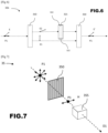
- the transmitter generates pairs of entangled photons by spontaneous parametric frequency reduction (SPDC), that is to say following a process in which an initial photon, also called “pump” photon, is split and its frequency halved by a four-wave mixing phenomenon, in an optical medium of nonlinear refractive index, as described in the article Amanti and. al, “Integrated sources of entangled photons at the heart of quantum technologies” (Photoniques, issue 91, 2018 ).
- SPDC spontaneous parametric frequency reduction
- This type of photon pair emitter makes it possible to produce photons whose entanglement is relatively robust, but has the disadvantage of sometimes producing more than one pair of photons at a time, which is not desirable because it is not controlled. . Additional devices can be put in place to process these multiple “parasitic” pairs, as described below.
- an emitter comprising a quantum dot to generate pairs of entangled photons, as described in the aforementioned article, which makes it possible to obtain pairs in a more regular manner.
- the entanglement properties of the photons obtained by such a method can nevertheless sometimes be unstable.
- optical fibers made of birefringent crystal as described in the article by Smith et. al “Photon pair generation in birefringent optical fibers” (Optics Express, Vol. 17, Issue 26, 2009 ).
- the transmitter is configured to successively generate a plurality of pairs of entangled photons.
- the entangled photons can be sent to the transmitter output on the first and second propagation paths in various ways.
- the photons are preferably emitted according to a predetermined polarization.
- predetermined polarization is meant in one of the two states of a predetermined pair of complementary polarizations, for example a linear polarization of a certain direction.
- a birefringent plate can, for example, separate the two entangled photons according to their vertical or horizontal linear polarization.
- a predetermined polarization of the entangled photons sent to each of the receivers makes it possible in particular to know the probability of a state according to a polarization or its complementary polarization for any selected pair of complementary polarizations.
- a predetermined polarization is also necessary when using quarter-wave plates at the first receiver to rotate the polarization direction of the first photon.
- a plate or a prism comprising an optically transparent birefringent material, for example lithium niobate or rutile (TiO 2 ), whose indices optics depend on the polarization axis of the light through which at least one of the two photons passes.
- an optically transparent birefringent material for example lithium niobate or rutile (TiO 2 )
- indices optics depend on the polarization axis of the light through which at least one of the two photons passes.
- This photon then exits the prism at one of two different locations, depending on its linear polarization.
- the source of entangled photons emits the two photons in the same direction and along an axis perpendicular to the ordinary axis of the optically transparent birefringent material, we collect at the exit of the prism, at the place through which the electromagnetic waves emerge from which the electric field is parallel to the ordinary axis of the optically transparent birefringent material, the first photon to send it to the first receiver.
- each of the two photons can be projected onto prisms birefringents in a direction perpendicular to the ordinary axis of each of the prisms and redirect each photon towards the receptor intended for it, the photons exiting through locations different from the prisms then being preferably lost or destroyed by projection onto an absorbent surface.
- birefringent delay plates converting the linear polarizations of said photons into circular polarization are preferably placed at the exit of the places from which the photons emerge from the prisms.
- Photons can be transmitted from transmitters to receivers through space, the atmosphere, an optical fiber, or a combination of these means.
- Lenses can be used for the transmission of photons, in particular for transmission through space or the atmosphere. If necessary, anti-reflective layers are preferably provided on said lenses.
- the size of the lenses used is preferably adapted to the length of the spatial or atmospheric transmission of the photons.
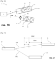
- conjugated mirrors which reflect the light emitted at the transmitter can be used.
- a laser light transmitter can, for example, explore a space in order to detect the receiver, the receiver reflecting back the emitted light and the direction of the rays. conjugated photons then being adjusted to be parallel or coincident with the direction of the light reflected by the conjugated mirrors.
- the light emitted by the laser light emitter can be of wavelength close to the wavelength of the entangled photons and be introduced through a dichroic prism into the objective used by the photons.
- the light can be introduced by a birefringent prism when said photons are of linear polarization, the polarization of the light used for guidance then being perpendicular to the polarization of the entangled photons directed towards the same receptor.
- a Pockels cell upstream of the receptors can be used to guide light towards the conjugated mirrors when the guide light arrives.
- the light waves used for aiming can be emitted parallel to the entangled photons but separated for example by a distance of a few centimeters to be reflected by the conjugated mirrors.
- the area to be explored can be identified by cartographic recognition of the area in which said receivers are likely to be found.
- phase modifier when the receivers are in relative rotation with respect to the transmitter, in particular because of the rotation of the Earth or the satellites, to allow the photons emitted in a fixed direction relative to the the transmitter to penetrate each of the receivers with a fixed and determined direction relative to it.
- these modifications can be different depending on whether the photons are directed towards the first or the second receptor. Finally, these modifications can vary over time depending in particular on the weather or the temperature of the materials during their use.
- the system according to the invention can be periodically calibrated by having the photons absorbed by the first receiver in polarizations belonging to predetermined pairs of complementary polarizations and by observing for each of these pairs one of the two possible polarizations in which the entangled photon is detected by the second receiver.
- the storage of states as well as the calculation of the Jones matrix are carried out by any suitable electronic device, for example a microcontroller.
- the Jones matrix thus calculated makes it possible to calculate the polarization of the second entangled photon received at the second receiver as a function of the absorption polarization of the first photon by the complex absorber located at the first receiver.
- a second calibration can be done, consisting of determining the probability for any photon arriving at the second receiver, whose entangled photon was absorbed during its transit to the first detector, of belonging to each range of pairs of complementary polarizations detectable or identifiable by the second receiver; the range of a P polarization being defined as all the polarizations assimilated by the polarization measuring instrument as being of P polarization.
- the measuring instrument of the second receiver preferably comprises at least one photon detector arranged to measure the polarization of the light resulting from the multiplication of the second photon.
- the measuring instrument of the second receiver comprises for example a succession of semi-reflecting blades arranged downstream of the optical amplifier, said blades directing the flow of multiplied photons, that is to say the luminous flux, with an equal intensity towards polarization measuring instruments arranged for example to measure the intensity of the flux along two perpendicular axes and/or the phase shift of the light between these same two axes.
- the light can also be directed towards various polarizing filters after passing through one or a succession of lenses which enlarge the section of the light beam, thus allowing a plurality of mirrors or lenses to direct portions of this light beam towards the various polarization measuring instruments.
- the measurement of the intensity of the light along two perpendicular axes is done for example by the separation of the light along two perpendicular axes by a blade or a birefringent prism followed by two light intensity sensors placed at the outputs of said blade or said prism.
- the measurement of the phase shift between two perpendicular components is done for example by the separation of the light along two perpendicular axes by a blade or a birefringent prism followed, for the wave polarized along one of the two axes, by a rotation of this polarization axis of 90°, for example thanks to a rotating or chiral material or by the succession of two quarter-wave plates, then a joint projection through Young slits of these two waves, one of which has undergone the rotation of its electric field, on a screen, the interference of the two light sources drawing fringes whose positions depend on said phase shift.
- optical amplifier is meant a device making it possible to duplicate a photon introduced there, in particular, the second photon of a pair of entangled photons, while retaining its polarization state.
- the optical amplifier is a doped fiber amplifier.
- EDFA erbium amplifier
- DFA doped fiber amplifier
- the optical amplifier is for example a vertical cavity amplifier (VCSOA), or even a semiconductor type amplifier (SOA).
- VSOA vertical cavity amplifier
- SOA semiconductor type amplifier
- anti-reflection layers are preferably placed at the interfaces between adjacent transparent media of different index crossed by the photons, as well as at the interfaces of the prisms and birefringent plates crossed by photons, the anti-reflection layer being adapted preferably to the index or indices of the material and the angle or angles of incidence and the directions of polarization as well as the wavelength of the photon which must pass through it.
- the first and/or second receiver preferably comprise one or more dichroic filters allowing only photons of a given wavelength to pass, in particular a prism made of a transparent dispersive material, the filter(s) being of preferably arranged in front of the measuring instrument or instruments, or in front of the optical selector for the first receiver, particularly if the refractive indices of non-linear materials are modified by application of powerful luminous flux.
- the photons arrive at the second receiver, it is useful to be able to differentiate whether they must be assigned to the transmitted information, whether it is information transmitted several times or whether it is a information that would not have been encoded on a pair of entangled photons.
- an SPDS type emitter as mentioned above can for example emit a double pair of photons without this being desired.
- the transmitter and each of the receivers preferably include a clock, the clocks of the transmitter and the receivers being synchronized with each other.
- the first receiver maintains an unchanged state until a time between, for example, a quarter of the non-transmission time after the end of the reception period and half of the non-transmission time ⁇ t' before the next reception period.
- the second receiver preferably records the bits received for each reception period. It then advantageously transmits to the first receiver from time to time, in particular if the device uses reflection to transmit a bit or a trit, for example every 3000 reception intervals, or every 100 reception intervals without photon, a list of periods reception for which it did not receive a photon, the transmitted photon having been lost or no photon having been emitted by the transmitter during this period, without the first transmitter knowing if it reflected any photons during these same periods, particularly if the device does not have a photon detector.
- the transmission of this list can be done by instantaneous communication using the method according to the invention described below, or by a conventional means of communication.
- the first receiver On receipt of this list, the first receiver then transmits the bits corresponding to these transmission periods, for which no photon has reached the second receiver.
- the first receiver only uses two different measuring instruments to transmit the information, one detecting linear polarizations, the other circular polarizations.
- the first receiver then retransmits each bit while selecting the measuring instrument appropriate to the bit it wants to transmit for this transmission period, and preferably keeps the selector in the same state until the end of the transmission period for which it receives a photon, allowing it to select the measuring instrument to use for transmitting the next bit.
- the second receiver by receiving the photons during the transmission periods, and if it receives them, measures their polarization state for each transmission period and deduces the bit that it must add to the list of bits received.
- the transmission line between the transmitter and the first receiver has a certain opacity and can absorb a certain proportion of the photons passing through it, some photons can arrive at the second receiver during reception periods with random polarizations.
- the second receiver can then be configured to recognize at least some of the photons arriving in a polarization state which cannot be that of an entangled photon absorbed or reflected at the first receiver.
- the clocks of the components of the system are configured to take into account the phenomenon of different flow of time in different locations, in particular the different altitudes of each of the components.
- a method can be implemented allowing the first and second receivers to synchronize their clocks.
- the first receiver notes using its own clock the time during which said photon struck the measuring instrument.
- the time noted is subsequently transmitted to the second receiver as well as, preferably, the references of the transmission interval, in particular the time of and optionally the duration during which the photon was waited.
- the second receiver notes the reception time of the second photon in order to adjust its own clock so that the offset between the start of the transmission period and the time during which the first photon struck the measuring instrument of the first receiver is the same as the offset between the start of the period of reception of the second photon at the second receiver and the time given by the clock for reception of the second photon.
- the transmitter can send photons in a predetermined number, or for a predetermined duration, and each of the two receivers can note the time of average reception of each of the photons then one of the receivers can communicate this said average time to the other receiver.
- the average time can be calculated by determining the average of the reception times of each of the photons or only of the first and last photon received.
- the predetermined number of photons sent or the duration of their sending are preferably adjusted in particular according to the transmission/loss ratio of photons on each of the two paths between the transmitter and the receivers, and the average frequency of sending of the photons.
- the transit times of the photons between the transmitter and each of the receivers being different, the synchronization of the clocks between each of the receivers can be different depending on whether information is transmitted in one direction or the other.
- Each of the receivers can then have a synchronization register used to increment or, on the contrary, subtract from the time of the clock of said receiver a period of time adjusted during synchronization, to deduce the time of a clock synchronized for the reception of information from the other receiver.
- a method can be implemented making it possible to synchronize the periods of sending photons to the receivers and the periods of reception to the receivers, these periods being time intervals during which photons can leave the transmitter or reach the receiver.
- the transmitter can emit a first brief light signal followed or preceded by other light signals composing a message, preferably signed by a digital signature indicating the precise time, on its clock, of sending the signal.
- the receiver On reception of said first light signal, the receiver notes the reception time then reads the sending time of the signal, determines the difference between the sending time of the signal and the time of the start of the photon transmission period, during which the signal was sent, or if it was sent outside a transmission period, the start of the previous transmission period, and does the same with the reception time of the signal and the start time of the reception period.
- the receiver may advance the start of the transmission period , or the opposite otherwise.
- the calibration is advantageously repeated several times and the results are averaged, this making it possible to adjust the clocks with a precision greater than the imprecision of the sending and receiving times of said light signals.
- the wavelength used for the light signal is preferably the same as the wavelength of the entangled photons, so that it can be transmitted at the same speed as the entangled photons.
- the first receiver may comprise detector-transmitters and a waiting element, for example a reflector arranged to reflect the first photon with a predetermined polarization different from the polarizations detectable by the detector-transmitters, or even an element arranged to absorb the first photon in a predetermined polarization different from the polarizations of the detector-transmitters.
- a waiting element for example a reflector arranged to reflect the first photon with a predetermined polarization different from the polarizations detectable by the detector-transmitters, or even an element arranged to absorb the first photon in a predetermined polarization different from the polarizations of the detector-transmitters.
- the polarizations of the detector-transmitters are preferably complementary, such that any photon directed towards an absorbing waiting element is absorbed.
- the detector-transmitters are preferably arranged to detect the polarization of the photons in at least four different polarizations, these polarizations being grouped into complementary pairs such that any photon directed towards a detector-transmitter is thus detected and absorbed whatever its initial polarization.
- the detector-transmitter(s) of the first receiver are used to send the information by selecting the pair of detectors used.
- the second receiver can thus detect an error in the transmission of information if: two consecutive photons of different polarizations not paired with photons sent to the waiting element are received in a time less than the rest period minus the inaccuracy of the receiver clock.
- This method has the advantage of not requiring the placement of a switch at the transmitter to restrict the emissions of entangled photons, nor clock synchronization.
- the detector-transmitters of the first receivers can also serve at the same time as a waiting element, in particular if the polarization in which they detect the photons is adjustable and can therefore be adjusted to the polarization used by the waiting element. to absorb photons.
- Optical amplifiers tend to emit photons in the opposite direction to the propagation signal, either during signal amplification or in the absence of a signal, after molecules or atoms of the amplifying medium have been excited by a pump signal.
- the second receiver includes for example a switch placed in front of the optical amplifier, in order to limit the number of photons emitted by the amplifier towards the source of entangled photons of the device.
- the switch of the second receiver is for example configured to absorb or reflect the photon(s) subsequent to a first photon reaching said second receiver in a predetermined time interval.
- the switch of the second receiver can be connected to the measuring instrument of the second receiver, in order to no longer let light pass in one direction or the other as soon as a first photon arrives and until the next photon is expected or a predetermined time before this moment, for example half of the rest period defined above.
- the switch of the second receiver can only let the photons pass during periods when they are expected, in particular during the aforementioned photon processing time intervals.
- Optical fibers although transparent, do not transmit all the photons presented at their entrance. A loss of 0.20 dB per kilometer is common, for example losing 10 dB in 50 km or 90% of photons.
- the effect of photons lost in transit between the transmitter and the first receiver is, however, different from the effect of the loss of photons lost during their transit to the second receiver; the entangled photons of the photons lost between the transmitter and the first receiver can arrive at the second receiver with any polarization corresponding to the polarization of the entangled photon absorbed in the line going towards the first receiver, then that the loss of a photon in the line leading to the second receiver necessarily causes the disappearance of a photon potentially carrying information, that is to say whose entangled photon has reached the first receiver.
- the polarizations of photons arriving at the second receiver after their entangled photons have been absorbed in transit to the first receiver are not necessarily equally distributed among all possible observable polarizations.
- the polarization absorber is systematically configured to absorb at least NPT photons in one of the two waiting polarizations after sending any information.
- the transmitter can sometimes send pairs of entangled photons very close together.
- the photon detectors located at the first receiver therefore preferably count the number of photons absorbed and not only the number of photon impacts on said first receptor. This counting can for example take into account the intensity of the electromagnetic wave incident on the photon detectors.
- the polarization detector can detect an average polarization of all the photons detected "simultaneously", the polarization of the groups of photons arriving simultaneously at the second receiver, that is to say whose light intensity generated is for example 50% greater at the intensity generated by a single photon, advantageously does not give rise to an increment of the photon counters received in various polarizations.
- An increased switching speed of the polarization of the complex absorber of the first receiver makes it possible to increase the sending frequency of the entangled photons sent by the transmitter.
- Increased temporal precision of the polarization detectors of the second receiver which makes it possible to discern the parasitism of various photons received very close in time to each other, also allows the use of a greater flux of entangled photons, but also of reduce the number of receptions of photons received “simultaneously”, as described above.
- This method has the advantage of not requiring the installation of a switch at the transmitter to restrict the emissions of entangled photons, nor clock synchronization.
- Photons are sometimes reflected back to the transmitter from the receivers.
- the cavity or material in which the entangled photons are produced by mixing waves whose refractive index is non-linear, is preferably surrounded or covered with a material absorbing light having a wavelength equal to that of the entangled photons.
- the pair of complementary photons is preferably selected from at least three different pairs of complementary polarizations.
- the pair of complementary polarizations is for example selected from 210 distinct pairs of absorption polarizations, in particular from polarizations spaced 9° apart in their direction of polarization and phase shifted by 9°.
- the polarization of the pair of entangled photons is indeterminate in the polarization(s) of the pair of complementary polarizations in which the instruments of the first receiver absorb them.
- the pair of entangled photons reaches, for example, the receivers with a linear entangled polarization, one of the two complementary absorption polarizations being circular, the second receiver being arranged to distinguish whether the average polarization of the flow of multiplied photons is circular or linear, and determine according to this distinction whether the first photon was measured or not.
- the pair of entangled photons reaches the receivers with a circular entangled polarization, the quantum state of absorption of the photons being a linear polarization, the second receiver being arranged to distinguish whether the average polarization of the flux of multiplied photons is circular or linear, and determine according to this distinction whether the first photon was measured or not.
- the pair of entangled photons reaches the receivers with a vertical or horizontal linear polarization, the quantum state measured at the first receiver being a linear polarization at 45° or -45° from vertical or horizontal, the second receiver being arranged to distinguish whether the average linear polarization of the flux of multiplied photons (P20) is at 45 or -45°, or the vertical or the horizontal, and determine according to this distinction whether the first photon has been measured or not.
- the system according to the invention and the quantum communication method described above make it possible to transmit between the first and the second receiver information either of binary type, in the form of bits, or discrete or continuous values.
- each pair of photons is generated successively by the transmitter, each pair of photons allowing the transmission of information, for example of binary type, from the first receiver to the second receiver.
- photons can be counted as they arrive at a polarization detector. If the counting reveals the arrival of more than one photon during a predefined time interval, the bit is not transmitted during this interval, and is for example transmitted in the next time interval or, preferably, the same bit is retransmitted again.
- counting the photons arriving in the time interval where they are expected can advantageously make it possible to create a temporary list of bits not received.
- a plurality of transmitters can be used.
- the system according to the invention may in particular comprise a second transmitter capable of generating one or more pairs of entangled photons, the second transmitter being located closer to the second receiver than to the first receiver.
- At least part of the photons can be made to travel an indirect path so as to extend their transport time to one of the receptors, for example by causing the photons to reflect on one or more intermediate mirrors, or by passing them through media with high refractive indices, or by transporting them in optical fibers of varying lengths.
- This elongated path can for example alternate at a fixed or variable rate depending on needs, with the non-elongated path so as to be able to use the entangled photons sometimes to transmit information from one point to another, sometimes in the other direction.
- Optical switches upstream of the receivers and synchronized with the switch attached to the transmitter capable of sending the photons over an extended path can be installed to send said photons to receivers corresponding to the first type of receiver, as described above, or on the contrary to the second type of receiver.
- a polarizing filter can be placed upstream of the second receiver.
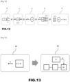
- the invention and in particular to the mixing of the first set of data with a mixing number before hashing, it becomes very improbable to be able to create data similar to this first set of data which, after having been mixed with the same number mixer, will have the same hash as the first mixed dataset.
- the method according to the invention does not require the simultaneous presence of two sets of data in the device.
- the mixer number is generated randomly.
- the mixer number is preferably generated by the device.
- the mixer number is generated by another trusted device.
- the generation of the mixer number can be carried out on the basis of a pair of input values which are physical quantities of which at least one varies continuously, such as for example temperature and time, or a quantum phenomenon.
- a generation can be based on which of the two Young slits a photon chooses to use to pass through a blade.
- step a) the mixing operation of step a) is carried out by the device.
- the mixing is carried out by another trusted device.
- the blend function combines the first data set and the blender number.
- This is preferably an XOR logic function which adds the bits of the first data set to those of the mixer number, one by one.
- the size of the mixer number is generally smaller than the size of the first data set, it is possible to add the bits of the mixer number to the first or last bits of the first data set by means of an XOR.
- the mixer number can be the same size as the first data set. In this case, the addition using the XOR function is performed on all bits, one by one.
- the mix function is a suffix function of adding the mixer number to the end of the first data set.
- the shuffle function can even be an encryption function using the shuffler number as the encryption key to encrypt the first set of data.
- the shuffle function is a combination of an XOR function, a suffix function of adding the mixer number to the end of the first data set, and an encryption function using the mixer number as the encryption key to encrypt the first data set.
- the data from step b) is hashed by the device.
- the hashing is performed by another trusted device.
- the hash function is chosen from SHA1, SHA2, SHA256 and MD5 and the Jenkins function.
- integrated of the message, we mean its non-alteration, for example by a malicious third party who intercepted it during its transmission.
- the message identifier may be a sequence of alphanumeric characters and/or signs that can be converted to a digital word using, among other things, an ASCII code.
- the message identifier may contain the sender identifier and a message sequence number.
- the authentication of the sender is ensured in particular by the decryption operation carried out in step vii.
- Decryption can be done using an encryption key that is kept secret between the device and the sender.
- the mixer number is kept secret and a renewable key having the size of the hash (third data set) is used, in particular with an XOR as an encryption function.
- Another solution is to keep the mixer number secret and use a non-renewing symmetric key with a symmetric encryption function.
- the mixer number is kept secret and a non-renewed asymmetric key pair with an asymmetric encryption function is used.
- the mixer number is kept secret and a non-renewed symmetric key with a symmetric encryption function is used.
- the mixer number is a renewable key and we use another renewable key having the size of the hash (third data set), in particular with an XOR as an encryption function.
- the mixer number is a renewable key and we use a non-renewable key having the size of the hash (third data set), in particular with an XOR as an encryption function.
- the mixer number is a renewable key and a non-renewable symmetric key with a symmetric encryption function is used.
- the mixer number is a renewable key and a non-renewable asymmetric key with an asymmetric encryption function is used.
- the identifier of the mixer number is exchanged between the sender and the device, which can each find the corresponding mixer number in a stored list of mixer numbers.
- the mixer number is generated randomly after each use.
- This mixer number can be encrypted by a one-time key.
- the mixer number can also be encrypted by a symmetric or asymmetric function.
- This first variant of the invention makes it possible to ensure both the integrity of the message received and the identity of the sender of the message.
- step i data received in step i is received by Wi-Fi
- step v data sent in step v is sent by 4G
- step vi data received in step vi is received by WiMAX.
- the device may also receive an identifier from the sender. This identifier is useful if the device is likely to receive messages from various senders, such an identifier allowing it to choose the encryption keys to use to encrypt or decrypt the information exchanged with the sender during encryption operations and decryption methods described in this first variant of the invention.
- the optional encryption of the mixer number in step iv is preferably performed by the device.
- Optional encryption of the mixer number helps prevent this number from being intercepted and modified by a malicious third party.
- the optional encryption of the mixer number is carried out using a one-time use key of size at least equal to that of the number. Since the key is single-use, a new key is used each time a mixer number is sent.
- Encryption can also be done using a symmetric key.
- the symmetric encryption key is kept secret between the sender and the device and is preferably renewed after a certain number of transmissions.
- the optional encryption of the mixer number is asymmetric, and is carried out either using a public key of the sender known to the device, so as to allow decryption by the sender using its associated private key, or using a private key of the device whose public key is known to the sender.
- step vii the decryption of step vii is carried out by the device.
- the decryption in step vii can be done using a symmetric key, if the encryption in step iv is done using a one-time key.
- step vii is carried out using a one-time key if the encryption of step iv is carried out using a symmetric key.
- step vii can also be carried out by other methods, for example using a public key known to the device, associated with a private key of the sender used to encrypt the hash received in step vi.
- the device is thus able to certify the identity of the sender.
- the mixer number can have the same size as the symmetric key that is used for encryption, if such a symmetric key is used, and also the same size as the hash.
- the private, symmetric, single-use encryption keys and mixer numbers are undetectable and unobservable by third-party devices, to prevent eavesdropping on data sent by the sender or device to generate and to transmit fraudulent second sets of data which would incorrectly recognize the integrity of messages received by the device but transmitted by a sender other than the one legitimately supposed to hold said keys.
- the encryption key Y is therefore a function F of the encryption key of functions F, and the values of the keys X and Y are located at the intersection of these functions. It is best to avoid this situation. It is therefore recommended either to use, for key X or key Y, values which change during transmissions, or to use encryption functions such as, for each observation of exchanges of the triplet "message, number encrypted, encrypted hash", the universe of keys Y for each possible X is large; to thus make large the universe resulting from the intersection of these deducible universes at each observation.
- the device may further include a counter of consecutive failed verification attempts, which triggers its blocking when a defined number is reached, the device being able to be unlocked during the renewal of the encryption key used to encrypt the mixer number or the encryption key used to encrypt the hash.
- the device can impose a predetermined number of successive unsuccessful verification attempts on messages arriving or sent by the same sender, predetermined number after which, and after a fixed period, the device places the messages received or the message sent by the same sender in a queue or, preferably, ignores them, before trying again either to decrypt messages placed in the queue or resuming decryption of messages that continue to arrive after the expiration of the fixed period.
- This approach is advantageously implemented by a device sending back to the sender of messages placed in a queue or ignored, a response message to inform him of the processing of his message. For example, three messages received consecutively from a sender that cannot be verified may cause the device to reject messages sent by that same sender for one minute, after informing said sender that their messages were ignored during that time.
- Decryption can be done using an encryption key that is kept secret between the device and the sender.
- the mixer number is kept secret and a renewable key having the size of the hash (third data set) is used, in particular with an XOR as an encryption function.
- the mixer number is kept secret and a non-renewed symmetric key with a symmetric encryption function is used.
- the mixer number is kept secret and a non-renewed asymmetric key pair with an asymmetric encryption function is used.
- the mixer number is kept secret and a non-renewed symmetric key with a symmetric encryption function is used.
- the mixer number is a renewable key and we use another renewable key having the size of the hash (third data set), in particular with an XOR as an encryption function.
- the mixer number is a renewable key and we use a non-renewable key having the size of the hash (third data set), in particular with an XOR as an encryption function.
- the mixer number is a renewable key and a non-renewable symmetric key with a symmetric encryption function is used.
- the mixer number is a renewable key and a non-renewable asymmetric key with an asymmetric encryption function is used.
- the identifier of the mixer number is exchanged between the sender and the device, which can each find the corresponding mixer number in a stored list of mixer numbers.
- step ii of the mixer number and the third data set is preferably carried out by the device.
- the encryption of the mixer number is carried out using a one-time use key
- the encryption of the third set of data is carried out using a symmetric key, the symmetric key preferably being renewed occasionally .
- the encryption of the mixer number is carried out using a symmetric key
- the encryption of the third data set is carried out using a one-time use key, the symmetric key preferably being renewed occasionally.
- the encryption of the mixer number and the encryption of the third data set may also be of the same type, or of different types, these encryption types may use symmetric keys or asymmetric keys.
- the private key of this pair is preferably kept by the device, the corresponding public key then being known to the sender.
- the encryption of the third set of data can be carried out using a private key kept by the sender, the corresponding public key then being known to the device.
- the device is able to certify the identity of the sender.
- the encryption of the mixer number and that of the third data set can be carried out using the same encryption function, in particular when the encryption of the mixer number is asymmetric.
- the encryption of the mixer number and that of the third data set are carried out by two different encryption functions.
- the types of encryption functions to be used are part of the configuration of the sender and the device, before establishing communication between the latter two.
- Decryption can be done using an encryption key that is kept secret between the device and the sender.
- the mixer number is kept secret and a renewable key having the size of the hash is used, in particular with an XOR as an encryption function.
- the mixer number is kept secret and a non-renewed symmetric key with a symmetric encryption function is used.
- the mixer number is kept secret and a non-renewed asymmetric key pair with an asymmetric encryption function is used.
- the mixer number is kept secret and a non-renewed symmetric key with a symmetric encryption function is used.
- the mixer number is a renewable key and we use another renewable key having the size of the hash, in particular with an XOR as an encryption function.
- the mixer number is a renewable key and we use a non-renewable key having the size of the hash, in particular with an XOR as an encryption function.
- the mixer number is a renewable key and a non-renewable symmetric key with a symmetric encryption function is used.
- the mixer number is a renewable key and a non-renewable asymmetric key with an asymmetric encryption function is used.
- the identifier of the mixer number is exchanged between the sender and the device, which can each find the corresponding mixer number in a stored list of mixer numbers.
- the mixer number is generated randomly after each use.
- This mixer number can be encrypted by a one-time key.
- the mixer number can also be encrypted by a symmetric or asymmetric function.
- the encryption of the mixer number in step ii and the decryption of the encrypted hash in step v are preferably performed by the device.
- the encryption of the mixer number is carried out using a symmetric encryption key shared with the second device.
- Encryption of the hash can be done using a one-time key and encryption of the mixer number can be done using a symmetric key that is renewed occasionally.
- encryption of the mixer number is done using a one-time key and encryption of the hash is done using a symmetric key that is renewed occasionally.
- Mixer number encryption and hash encryption may also be of the same type, or of different types, these types of encryption may use symmetric keys, in particular one-time keys, or asymmetric keys.
- the invention can be used in quantum communication processes, in particular in Quantum Key Distribution E91, where a pair of entangled photons is used to generate a secret shared between two photon receivers.
- a signed message can be exchanged between the two receivers before using the sixth and seventh lists as one-time keys.
- the polarization measurement bases can be made to rotate randomly and simultaneously by the same angle kept secret between the two receivers.
- the sixth and seventh lists can be used as lists of random rotation angles of the polarization measurement bases.
- the photons are preferably sent in a fixed polarization which is not the polarization of the photons that can be measured by the receivers, the photons being able for example to be sent in circular polarization, while being detected in states of orthogonal linear polarization, or sent in linear polarization in a direction which is not the direction of the polarization in which they can be detected, preferably fixed at 45° from the direction of linear polarization in which the polarizations of the photons are detected by the receivers.
- the direction of the polarization angle at which the polarizations are detected by the receivers can be changed periodically and randomly by the same angle on both receivers, the change preferably being a change of 0° or 45° and, preferably, l the linear polarization angle at the emitter being modified by the same angle if the emitter actually emits the linearly polarized photons.
- the change can occur every millisecond.
- the angle of the polarization can be modified, for example by means of a bypass circuit intended for the photons upstream of the receivers, a first switch capable of diverting the incident photon towards a device for rotating the polarization of the photons and a second switch allowing sending the photon exiting said polarization rotation device to said receiver, such that, in a first mode, the photons bypass the polarization rotation device, while in another mode, the photons pass through the polarization rotation device before entering the receptors.
- the photon rotation device can be made, for example, of a chiral material such as CdSe nanoparticles of 1.4 to 2.4 ⁇ m (source: inorganic Nanostructures with Strong Chiroptical Activity Anastasia Visheratina & Nicholas A.
- a device consisting of a first birefringent prism separating the light into two beams of linearly polarized light which each pass through two quarter-wave plates forming an angle between them, such that the light leaves the second plate quarter wave linearly polarized at a certain angle relative to the direction of polarization at which it reaches the first quarter wave plate, the two beams of linearly polarized light leaving the second quarter wave plates being united into one beam by passing through a second birefringent prism.
- Angle changes can be set in accordance with single-use keys shared between the two receivers and, if necessary, the sender. If the angle change is only applied to both receivers, for example if the sender sends the photons in a state circular polarization while readers read photons in a linear polarization state, the one-time key can be renewed using keys generated by the Shared Quantum Key generation process described here.
- the path of the photons is preferably physically protected against the insertion of a spy device in a first zone, in its part where the photons propagate without being entangled.
- the path of the photon is longer by a length measured between the photon emitter and the second photon receiver than between the emitter and the first photon receiver, the path followed by the photon between the transmitter and the second receiver is physically controlled at least near the second receiver for said measured length.
- said length can be physically measured, particularly if the photons propagate in optical fibers.
- the measurement can for example be carried out by having placed truly synchronized clocks on the two receivers (as opposed to the synchronized clocks described above), and by having verified at the time of this measure that no spying device has been inserted between the transmitter and the receivers.
- the path of the photon is preferably physically protected in a second zone located upstream of the first zone, if it exists, or upstream of the detector, if the first zone does not exist, against the insertion of a spy device.
- This second zone is configured so that the photon propagates there for a time greater than the uncertainty of the arrival time at which the photons are detected at the two receivers.
- this spy detector will detect the photons and their polarization before re-emitting photons of the same polarization towards the second detector. However, this re-emitted photon will have to pass through the first zone and the second zone, thus arriving at a different time from that where it would have arrived if no spying device had interfered, and this time difference being perceptible by the second receiver.
- a spy transmitter may send a first photon entangled with a second photon to the first legitimate receiver and detect the polarization state of the entangled first photon by checking the polarization of the second photon. However, to transmit this polarization state to the second transmitter, it will have to send a polarized photon in the appropriate state, but this photon will first have to propagate towards the second protected zone, then travel through the protected zone, this requiring more time and, therefore, will arrive at a different time than when the initial spy photon was detected by the first receiver.
- a spy device sends to the second receiver a first photon entangled with a second photon and detects its polarization state, it could then send to the first receiver a photon having the same polarization; however, this photon will arrive after the second receiver has received its detected photon, therefore at a time, according to the "synchronized" clocks, different from the time when the other photon arrived at the second receiver.
- the sizes of the first and third lists are preferably chosen with a tolerance coefficient such that the sixth and seventh lists have a reasonable chance, for example at least 50% chance of being equal, if nothing has interfered during the process transmission of entangled photons.
- the sixth and seventh lists can have a length of 500 bits and the first and second lists can have 5000 successive reception times if 90% of the entangled photons are lost between the photon transmitter and the receivers, each photon receiver, whatever or the receiver, having only a 10% chance that its entangled photon was received by the other receiver.
- the method according to this fourth variant does not require storing the data set in a secure manner.
- the invention also relates to a computer program product containing instructions readable by a processor of an apparatus for implementing the method according to the invention, according to any of the variants defined above.
- FIG. 1A a quantum communication system 1 according to the invention.
- the system comprises a transmitter 2 emitting a pair of entangled photons (P1, P2), the first photon P1 propagating on a propagation path D1 and the second photon D2 propagating on a propagation path D2 different from the path D1. Photons P1 and P2 are emitted simultaneously.
- wave Due to the nature of light and the wave-particle duality of the photon, the terms "wave”, “photon” and “particle” are used interchangeably in the following to designate the product emitted by the transmitter 2.
- measuring instrument and “absorption instrument” are used interchangeably to designate an instrument absorbing a photon according to a certain polarization.
- System 1 comprises a first receiver 3, located on the propagation path D1 of the first photon P1, and a second receiver 4, located on the propagation path D2 of the second photon P2.
- Receiver 3 is closer to transmitter 2 than receiver 4, so that photon P1 reaches it before photon P2 reaches receiver 4. Photon P2 reaches, for example, receiver 4 after a additional travel time t tra corresponding to an additional travel path Ltra.
- the receiver 3 comprises a complex absorber 31 comprising a polarization modifier 32 and an absorption instrument 35.
- the complex absorber 31 is configured to absorb the photon in a polarization state selected from several pairs of different complementary polarizations, preferably at least three pairs.
- the polarization modifier 31 is configured to transmit the photon P1 according to the selected pair of complementary polarizations and the absorption instrument 35 makes it possible to determine in which of the two states of the pair is the photon P1.
- the polarization state of the photon P1 is a superposition of the two states of the selected pair, weighted by certain probabilities, for example in an equiprobable manner.
- the receiver 3 comprises two measuring instruments 35 arranged to measure the quantum state of the first photon P1, and an optical selector 30 arranged upstream of the measuring instruments 35 and configured to send the first photon P1 either to a prism birefringent 36 which conducts the photon, according to the linear direction of its polarization, on paths D1' or D1" then towards one or the other of the measuring instruments 35, or prevents it from being measured, for example by reflecting it on a propagation path D3 different from the path D1.
- the direction D3 is chosen in particular so that the photon P1 is not absorbed before its entangled photon is multiplied at the second receiver 4.
- the system 1 preferably comprises, as illustrated, a device 5 for protecting the quantum state of a photon placed near the receiver 3, in particular on the propagation path D3 in the example considered.
- This device makes it possible for example to "trap" the photon P1 in the case where it is reflected by the optical selector 30 on the path D3, in order for example to prevent it from being measured or absorbed at least until the second photon P2 has reached the second receiver 4.
- a 5D photon detector (not shown) can be placed at the end of the device 5 to detect the photons which have been captured there, after their entangled photons have reached the second receiver .
- the second receiver 4 comprises an optical amplifier 40 making it possible to multiply the second photon P2 while preserving its polarization and a measuring instrument 45 making it possible to measure the average polarization of the multiplied photons.
- Photons P1 and P2 can take place in various ways, and in various environments. Photons propagate for example in an optical fiber or a waveguide, or even freely in space, the space being empty or filled with gas.
- Photons can pass through several media, presenting different refractive indices.
- anti-reflective blades can be inserted between two crossed media, if necessary, in order to avoid unwanted optical phenomena, in particular Fresnel reflection of the waves emitted by the transmitter 2.
- the transmitter 2 includes for example one or more selected lenses of sufficient size so that the photons reach their respective receiver with low diffraction, for example allowing at least 99.99% of the emitted wave to reach the receiver.
- the transmitter 2 may also include a system, in particular an electronic device, making it possible to adjust the initial directions in which the photons P1 and P2 are respectively emitted.
- This adjustment can for example take into account the different refractive indices of the media crossed, and the modification of the trajectory of the photons which can result therefrom, for example for a photon emitted from space which enters the atmosphere.
- the wavelength of the emitted wave is for example selected according to the medium(s) to be crossed; for example, we will preferably use photons in the infrared domain when they must pass through the atmosphere or air.
- the transmitter 2 generates, for example, pairs of entangled photons using the spontaneous parametric frequency lowering (SPDC) process.
- SPDC spontaneous parametric frequency lowering
- the transmitter 2 is for example configured to emit on average less than one pair per unit of time, for example one pair per nanosecond, which corresponds to a photon transmission frequency of 1 GHz.
- the photons P are for example linearly polarized, that is to say that the corresponding electromagnetic wave has an electric field whose direction is perpendicular to its direction of propagation D.
- the polarization photons can be vertical V or horizontal H, as illustrated in Figure 2A .
- the quantum state corresponding to the polarization of the photons is sometimes undetermined until it has been measured or absorbed. Before being measured, the quantum state of the photon is therefore sometimes considered as the superposition of possible states, namely, in the example considered, as the superposition of a polarization at an angle of 45° and a polarization at an angle of -45°.
- the P photons, when emitted, are circularly polarized, that is to say that the direction of the corresponding electric field changes according to a rotational movement, while its norm remains constant.
- the polarization of the photons is defined by the direction of rotation of the electric field, either clockwise C1 or counterclockwise C2.
- the linearly polarized photons are in an indeterminate quantum state, considered as the superposition of two circular polarization states with opposite directions of rotation.
- the blade 6, depending on its orientation, converts for example the linear polarization of a photon into circular polarization by advancing or delaying the electromagnetic waves propagating along an axis perpendicular to the ordinary axis of the crystal with an electric field perpendicular to the same axis relative to the wave having an electric field parallel to said ordinary axis.
- the photons emerging from the plate 6 are for example transmitted by an optical fiber 7 to another quarter-wave plate which converts the circularly polarized fields into linearly polarized fields, before propagating towards the receivers 3 or 4.
- This conversion of the polarization of the photons emitted makes it possible in particular to avoid having to take into consideration at the level of the receivers the direction of the polarization of the photons emitted by the transmitter.
- the optical selector 30 can be produced in various ways, some examples of which are illustrated in figures 4A to 4D.
- the optical selector 30 comprises, for example, a mirror controlled by liquid crystals as illustrated in Figure 4A , comprising a blade 370 enclosing liquid crystals.
- electrodes 315 and 320 are placed on opposite sides of the blade 370 in order to subject the liquid crystals to an electric field, making it possible to control their refractive index n C.
- the incident photon P1 can be reflected on a propagation path D3, or it can pass through the plate 370 and be transmitted on a propagation path D1', which can be identical or different from the path D1, towards measuring instrument 35.
- the photon P1 passes through the liquid crystal plate 370 and emerges along D3 or D1', the directions D1, D1' and D3 being, in the example considered, parallel.
- a mirror 325 in particular a Bragg mirror, can be placed on the propagation axis D3 in order to reflect the photon in another direction, for example towards the protection device 5.
- Anti-reflection blades can advantageously be placed on each of the faces of the blade 370 and adjusted according to the entry and exit angles of the photon when it passes through it.
- the optical selector 30 is a mirror controlled by non-linear fibers. It comprises two optical fibers 330 and 335. Fiber 335 is for example formed of a non-linear material.
- the first photon P1 upon arrival at the first receiver, enters the fiber 330.
- a light signal F also called "control signal”.
- the signal F is a light wave of high intensity, for example emitted by a laser, and of wavelength different from that of the photon P1.
- the photon P1 remains in the fiber 330 before, for example, crossing at the fiber output a prism 345 placed on a propagation path D3.
- a mirror 325 in particular a Bragg mirror, can be placed on the propagation axis D3 in order to reflect the photon in a desired direction, for example towards the protection device 5 or, directly back into 330 fiber.
- photon P1 is transmitted from fiber 330 to fiber 335.
- Photon P1 emerges from fiber 335 and passes through, for example, a prism 340 before being transmitted, for example towards the measuring instrument 35.
- the prism 340 is preferably made of a dispersive material making it possible to bring out the illuminating light from a different location and in a direction different from that of the photon.
- a Bragg mirror (not shown) reflecting only said illuminating light and allowing the photon to pass can be placed between the fiber 335 and the prism 340, for example to reflect said illuminating light in a direction other than towards the prism. 340 or even in fiber.
- Anti-reflection blades (not shown) can be placed at the entrance and exit of the prisms 340 and 345 and adjusted to the wavelength of the photon P1.
- the polarization modifier 32 preferably comprises a polarization direction modifier 32a disposed upstream of a phase modifier 32b.
- the polarization direction modifier 32a comprises a stack of blades 560, in particular quarter-wave blades, oriented differently relative to each other, as illustrated in figure 5A , so that a circular wave 558 penetrating one of these quarter-wave plates emerges as a wave 511 linearly polarized in a direction associated with said plate.
- These blades can be designed to operate with waves 558 penetrating them in a direction parallel to the bisector of their edges 521 and 522.
- These blades are preferably composed of uniaxial birefringent crystals such as for example rutile. This birefringent crystal can make up their entire mass or be concentrated on a slice for example on one of the edges 523 crossed by the wave 558, as illustrated in the figure 5A .
- blades can be juxtaposed with each other to form a structure 524, as illustrated in Figure 5B , so that the outgoing waves 511 or 512 have a linear polarization whose direction of the electric field depends on the location of penetration, in the assembly 524, two waves 558 or 559 circularly polarized and in a direction parallel to the bisector of the edges 521 and 522.
- a wave 556 of determined direction and linear polarization penetrating into the quarter-wave plate 551 crosses it in direction 557 to become of circular polarization before penetrating into a crystal 552 whose refractive index is adjustable, by example under the effect of an electric field generated by electrodes 516, then preferably penetrates into another crystal 553 whose refractive index is also adjustable, for example under the effect of an electric field generated by electrodes 517 generating an electric field perpendicular to the field generated by the electrodes 516.
- Two circularly polarized waves 558 and 559 then emerge from the crystal 553 and enter the assembly 524 in different locations depending on the selection of the refractive index imposed on the crystal 553.
- the direction of the light ray being different depending on these locations, the direction edges 520 and 521 is preferably different for each element 560 of the assembly 524.
- the waves 511 and 512 therefore constitute two possibilities for the light ray to pass through the assembly 524. These waves leave the assembly 524 linearly polarized in different directions and having the same direction of propagation but in different locations on the edge 514 of the assembly 524.
- the crystals 552, 553, 554 and 555 are for example E7 liquid crystals from Merck at the terminals of which the electrodes apply for example voltages of between 0 and 5000V if the distance between the electrodes of each of the pairs is 5 mm, making it possible to vary their refractive indices between 1.5 and 1.67.
- the electrodes are preferably covered with a dielectric film.
- refractive indices modified by the electric fields can be different depending on the relative direction of the electric field of the light and according to the direction of the electric field, the application of successive perpendicular electric voltages makes it possible to modify the refractive index for each of the two components of said light, this being the superposition of waves whose electric field is perpendicular to the Figure 5B and waves whose electric field is perpendicular to the direction of propagation and in the plane of the figure.
- the wave linearly polarized in a determined direction enters a first quarter-wave plate transforming its polarization into circular polarization, then a second quarter-wave plate wave transforming this circular polarization into a linear polarization in an adjustable direction depending on the orientation of this second quarter-wave plate.
- the orientation of the second quarter-wave plate is obtained for example by mechanical control of a sensor, or of an electrically controlled device allowing its rotation, for example by rubbing on a shaft set in motion by a piezoelectric material or by an electric motor device, for example direct current.
- liquid crystals are used to control the rotation of the linear electric field of the incident photons 526 linearly polarized in the same direction of polarization, which begin for example by crossing, preferably perpendicularly, one of two transparent electrodes 527 of 0.2 ⁇ m coated on one of its faces 528 with a material orienting the liquid crystal particles 529 adjacent to said face 527 in the direction of the polarization of the incident photons 526, then pass through the liquid crystal 529 over 2 ⁇ m before crossing the second transparent electrode 527 whose face 528, preferably parallel to the first electrode, is also coated with a material making it possible to align the liquid crystals but in a direction perpendicular to the direction imposed by the coating of the first electrode.
- the direction of the liquid crystals between the two electrodes is thus gradually modified from 0° to for example 60° relative to their initial orientation.
- the application of an electrical voltage of, for example, between 0 and 1 V gradually reorients the liquid crystals to impose a direction on them along the axis of the direction of propagation of the photons, thus gradually reducing the difference in refractive index of the liquid crystals between the two polarizations perpendicular to the movement of the photons and the rotating power of the device.
- This device therefore makes it possible to continuously select the output direction of the polarization of the incident photon between 0 and 60°.
- Devices such as that illustrated in Figure 5B are advantageously used in a device similar to that described above and illustrated in figure 5A , for example placed between the blades 524 and 554, each of for example 4 elements 560 making it possible to place the linear polarization of an incident photon in one of four precise directions, for example -90°, -45°, 0° and +45°, then each of the devices described in Figure 5B placed successively, and preferably aligned with the direction of propagation of the photons leaving the devices 560 which precede them, making it possible to add to this rotation a rotation of any angle, for example between 0 and 45°.
- the phase modifier 32b comprises a first blade or birefringent prism 370 arranged to divide the incident photon P1 of polarization field E into two electromagnetic waves of linear polarization E 1 and E 2 on two different axes x 1 and x 2 .
- a delay plate 321 of variable refractive index for example comprising a Pockels cell such as lithium niobate, controlled by electrodes 322 or a non-linear material, so as to acquire to the wave E 2 oriented along the second axis x 2 a predetermined phase shift relative to the wave E 1 oriented along the first axis x 1 .
- Another birefringent plate 370 is placed at the output of the phase modifier 32b, making it possible to bring together along the same axis x the two waves whose polarization fields E1 and E2 are perpendicular into a wave or photon P1 of field E' having acquired a phase shift with respect to the field E.
- a simple Pockels cell 321 can be used with the electrodes 322 but without the blades 370.
- the measuring instruments 35 of the first receiver 3 can be of various types and include various elements. The latter depend in particular on the nature of the polarization of the photon P1 when it is emitted by the emitter 2. Some examples are illustrated in figures 7 And 8 and described below.
- the measuring instrument 35 comprises a polarizing filter 350 placed on the propagation path D1 of the photon P1 and a photon detector 355 placed on the same propagation path, downstream of the filter 350.
- the polarizing filter 350 only allows photons having a certain linear polarization to pass and absorbs those whose polarization is perpendicular to them. It therefore makes it possible to select photons having a linear polarization of a certain direction.
- the polarizing filter 350 is a grid formed of vertical wires, for example metallic. It only allows photons with horizontal linear polarization H to pass.
- the measuring instrument 35 comprises an anisotropic plate 360, for example a birefringent plate, a birefringent prism or two birefringent prisms joined together.
- the plate is for example made of barium beta borate (BaB 2 O 4 , BBO).
- the photon P1 whose quantum state must be measured reaches the plate 360 on an incident propagation path D1, and is transmitted on one of two propagation paths D11 or D12, depending for example on whether its polarization is in the plane of blade 360 (that is to say, perpendicular to the plane of the figure 8 ), or normal to the plane of the blade 360.
- the measuring instrument 35 further comprises two detectors 355, each placed on a propagation path D11 or D12 of the photon P1.
- all photons can be detected by detectors 355, whatever their polarization.
- a quarter-wave plate is placed upstream of the anisotropic plate 360 in order to convert a circular polarization of a photon into linear polarization, and thus detect the direction of rotation of a circularly polarized photon.
- the second receiver 4 may include different types of optical amplifier 40 and measuring instrument 45.
- a doped fiber amplifier is used as illustrated in Figure 9 .
- the amplifier 40 comprises a fiber 400, in particular a fiber made of non-linear material, into which the second photon P2 is introduced after passing through a dichroic prism 451 when it reaches the receiver 4.
- An electromagnetic control wave F serving to provide energy and multiply the photon P2 is introduced by a fiber 450 into the same dichroic prism 451 at a point and with a direction such that it emerges from the fiber 400 just like the photon P2 , the photon P2 and the control wave F having different wavelengths.
- the control wave F is preferably of high light intensity and preferably of shorter wavelength than that of the photon P2.
- the photon P2 is multiplied into N photons P20, then these N photons and the flux F pass through a second dichroic prism 452 from which they emerge in different directions.
- the N photons are then advantageously directed towards a measuring instrument 45, making it possible to determine the polarization of the light flux and examples of implementation of which are given in Figure 10A and 10B .
- the N multiplied photons P20 are measured with a polarization which can be deduced from the absorption polarization of the photon P1 using the Jones matrix calculated during a calibration as described above.
- the measuring instrument 45 may include a succession of semi-reflecting blades 452 and a mirror 453, as illustrated in Figure 10A .
- the blades 452 and the mirror 453 direct the multiplied photons P20, which form a luminous flux, for example towards prisms made of birefringent materials 350 preferably having equal intensity.
- the filters 350 divide the luminous flux into two orthogonally polarized luminous fluxes, so that the detectors 455 can either determine the intensity of said flux in each of the orthogonal directions, or determine the phase shift between the two orthogonal components of the flux, for example by a Michelson interferometer or a Young slit interferometer.
- the interferometers are preferably arranged so that the light paths of the two orthogonal components are identical, the light flux coming from the multiplication of a single photon being very brief.
- FIG. 10B represents an example of such a Young slit interferometer.
- Two waves 460 and 463 come from the prism 350.
- the wave 460 passes for example through a prism 461 straightening its direction of propagation so that it becomes at 462 parallel to the wave 463.
- the wave 463 passes for example through through a half-wave plate making it possible to align the electric field of said wave 465 with that of wave 462.
- Waves 462 and 465 then pass through two holes perforated in a screen 466 before interfering with one another to form fringes on a screen 467 observed by a camera or equipped with photosensitive sensors making it possible to determine the position on said screen 467 of the brightest fringe.
- Information can be transmitted, in particular binary type information, between receivers 3 and 4 of a system 1 such as that described in section Figure 1B , for example by following the steps illustrated in Figures 11A and 11B .
- the correspondence protocol between the information to be transmitted for example, between sending a "0" bit or a "1" bit, and the measurement, or not, of the first photon P1, is determined before the start of the transmission.
- step 10 two entangled photons P1 and P2 are emitted simultaneously from a transmitter 2 to receivers 3 and 4, respectively, the receiver 3 being placed closer to the transmitter 2 than the receiver 4, as described above.
- the emitted photons P1 and P2 present an indeterminate quantum state in a predetermined pair of complementary polarizations, for example a 45° polarization if they are linearly polarized (the complementary polarizations being 0° and 90).
- step 11 the photon P1 reaches the optical selector 30 of the receiver 3.
- the photon P1 is for example reflected by the optical selector, on a perpendicular path in the example illustrated in Figure 11A (but any other path is possible), so as not to be able to reach the measuring instrument 35.
- the photon P1 can in particular be trapped in step 12 in a device for protecting its quantum state 5, in order to avoid its absorption, at least as long as the second photon P2 has not reached the second receptor 4.
- the photon P1 for example, retains its polarization at 45°.
- the photon P1 passes through, for example, the optical selector 30 to head towards the measuring instrument 35, as illustrated in Fig. Figure 11B .
- the quantum state of the photon P1 is then measured by the measuring instrument 35, in step 13.
- the photon P1 now has a determined quantum state, for example a vertical polarization (90°), or a horizontal polarization (0°).
- a determined quantum state for example a vertical polarization (90°), or a horizontal polarization (0°).
- the measurement carried out in step 13 projects the entangled photon P2 into a determined state.
- step 15 whatever the information to be transmitted, the photon P2 reaches the optical amplifier 40 of the second receiver 4, where it is duplicated into a flow of multiplied photons P20, each photon P20 having retained the polarization of the photon P2.
- step 16 the polarization of the photon flow P20 is measured by a measuring instrument 45.
- a quantum state corresponding to a measurement in the first receiver 3 is obtained, for example a vertical (90°) or horizontal (0°) polarization, we deduce that the first photon P1 has been measured, and a bit "1" is received.
- step 10 two entangled photons P1 and P2 are emitted simultaneously from a transmitter 2 to receivers 3 and 4, respectively, for example with linear polarization.
- step 17 the photon P1 reaches the polarization modifier 32, which converts the linear polarization of the photon P1 into a selected pair of complementary polarizations, the pair having been selected according to the Jones formalism and corresponding to a discrete value to be transmitted .
- step 13 the photon P1 is absorbed by the instrument 35 in one of the two complementary states of the selected pair, at the same time projecting the entangled photon P2 into its complementary state.
- the invention is not limited to measuring a linear polarization of photons. Other types of quantum state may be measured and/or other means of measurement may be used, including measurements in other observable bases.
- the photons P1 and P2 are for example emitted with a circular entangled polarization, and the measuring instrument 35 projects, by measuring a linear polarization, the photon P1 and by entanglement the photon P2, into a linear polarization base.
- the photons P1 and P2 are emitted with a linear entangled polarization, and the measuring instrument 35 projects, by measuring a circular polarization, the photon P1 and by entanglement the photon P2, according to this observable basis.
- the photons P1 and P2 are emitted with an entangled linear polarization vertically or horizontally and the measuring instrument 35 measures a linear polarization at 45° or -45° from the vertical or horizontal.
- the receiver 3 comprises two measuring instruments 35, one measuring a linear polarization, the other measuring a circular polarization.
- the optical selector sends for example the photon P1 towards the first measuring instrument if a "1" bit must be transmitted, towards the second measuring instrument if a "2" bit must be transmitted, and prevents it from being measured if a “0” bit must be transmitted.
- the measuring instrument 45 of the second receiver 4 can be configured to detect whether the first photon P1 was measured or not, and, if so, with what polarization it was measured at the first receiver.
- Gyroscopes can further be used at transmitter 2 and receivers 3 and 4 to determine the direction of polarization of photons P1 and P2, if these are emitted and transported to the receivers with linear polarization.
- the receivers 3 and 4 as well as the device 5 can be provided with devices intended to count the photons during their absorption, and optionally after waiting for the absorption of their entangled photon, which can be accompanied by 'a timestamp of their arrival, as shown in Figure 13 .
- This can make it possible, for example, to control the correspondence between pairs of entangled photons and the transmitted bits.
- Each photon triggers for example the timestamping process by arriving at the receiver in step 80, in particular by reaching one of the measuring instruments 35 or 5D.
- the receiver 3 copies for example in step 82 the current time H on the clock of said receiver, for example recorded in a register R, on a free memory register M, preferably after subtracting from the arrival time at the detector 5D the transit time of the photon in the waiting device 5.
- a similar device (not shown) can be arranged at the second receiver 4.
- the clocks allowing the timestamping which has just been described are synchronized for the two receivers 3 and 4, which optionally makes it possible to define time intervals for processing the photons common to the two receivers, and to process the double pairs “multiples” of photons emitted by transmitter 2.
- the second receiver 4 may also include a switch 50 placed in front of the optical amplifier 40, and is configured to absorb or reflect any unwanted photons PE2 which reach the receiver 4 after the photon P2 during the same interval processing time, as shown in Figure 14 .
- the switch 50 can also absorb any PA2 photons emitted by the amplifier 40 towards the transmitter 2 during the amplification of the signal, or during the de-excitation of molecules or atoms of the amplifying medium.
- the switch 50 is for example controlled by an electronic mechanism (not shown) itself controlled by the measuring instruments 45 when these or one of them detects photons.
- the system according to the invention may include several transmitters arranged differently relative to the receivers, in particular in order to establish bidirectional communication.
- system 1 comprises two transmitters 21 and 22, each emitting pairs of entangled photons towards two receivers 91 and 92.
- the transmitter 21 is closer to the receiver 91 than to the receiver 92, and the transmitter 22 is closer to the receiver 92 than to the receiver 91.
- This arrangement allows the receivers 91 and 92 to communicate bidirectionally; the photon P11 emitted by the transmitter 21 arrives first at the receiver 91, which can then act as first receiver 3, that is to say transmit information to the receiver 92 which receives its entangled photon P12 and acts as second receiver 4.
- the photon P21 emitted by the transmitter 22 arrives first at the receiver 92, which this time makes it possible to transmit information to the receiver 91 which receives the entangled photon P22.
- the mechanism for transmitting information, particularly binary information, is for example similar to what was described above, to figures 11 And 12 .
- Reflection devices 93 and 94 can be placed near the receivers 91 and 92, respectively, in order to reflect the photons possibly reflected by the receivers 91 and 92.
- the system of Figure 16 was modified by the addition of at least one polarizing filter 46 at the input of the receiver 4, this filter having a direction of polarization which corresponds to that expected for the photons having traveled from the transmitter to the receiver 4.
- the filter polarizer 46 is thus placed upstream of the change in polarization of the photons initiated by the receiver 3 transmitting the information to the receiver 4.
- the filter 46 prevents a fraudulent receiver from replacing the authentic receiver 4, from observing the exact polarization of the entangled photon after multiplication of said photon, then from transmitting to the authentic receiver 4 a fraudulent photon, in replacement of the authentic photon, to be necessarily observed by the receiver 4 in the same relative polarization as the authentic photon, because on the one hand, if said photon is not entangled with another photon, its polarization will not change after passing through the filter 46 and will therefore have the polarization imposed by the filter 46 and not that of the authentic photon, and on the other hand, if the fraudulent photon is entangled with another photon called the second fraudulent photon, it is not possible to impose the relative polarization of these photons fraudulent nor otherwise destroy or stop said fraudulent photon after it has passed through the filter 46, if the verification of the relative polarization of its entangled photon is then verified as inadequate, by a third party device.
- the second receiver 4 After a determined number of photons carrying information I have been received, the second receiver 4 generates a message including the precise detection time and the polarization for each of the photons for which these attributes have been noted and having been retained as transmitting information and therefore belonging to a group of NSP photons or more having a given polarization or the polarization complementary to this polarization; NSP is defined above as the predetermined threshold number of photons received in a given polarization or its complementary polarization making it possible to identify the reception of information.
- This message is signed, preferably using the random hashing technique described in the request US 20210165914 A1 , by the receiver 4, then is sent to the receiver 3 with said signature, preferably by implementing a means of quantum transmission as described above, then the signature of the message received is verified, as well as the correspondence of the relative polarizations of the photons received by the two receptors for the pairs of photons whose two photons reached the receptors.
- This information I can be declared not to have been listened to during its transmission between the two receivers if the verification of the signature makes it appear authentic and the proportion of polarizations not corresponding is less than a given threshold, for example 1% if 450 pairs of different polarizations are used, or a multiple such as 2 of the probability that two different pairs of entangled photons are emitted at times indistinguishable by the receivers.
- a given threshold for example 1% if 450 pairs of different polarizations are used, or a multiple such as 2 of the probability that two different pairs of entangled photons are emitted at times indistinguishable by the receivers.
- a relative polarization in each of the pairs of polarizations of the photons having been retained to have transmitted the information I can be used to form a sequence of bits forming a randomly generated key known only to each of the receivers; the receiver 3 having carried out the verification of the concomitance of the relative polarizations will send to the other receiver 4 a signed message, preferably by the random hashing technique, formed from the list of dates of reception of the photons whose relative polarizations did not correspond or whose entangled photon has never been received by receiver 3.
- the receiver 4 receives, from the transmitter 2, a flow of photons conveying information and establishes a first list of the dates of reception of the photons used to determine this information as well as the relative polarization designating that of the two complementary polarizations in which the photon has been received.
- the receiver 4 forms a message consisting of the list of information collected in the previous step, creates an electronic signature of this list and transmits said list as well as the signature to the receiver 3.
- the receiver 3 receives the list and the signature then verifies said signature.
- the receiver 3 establishes a second list consisting of the elements of the first list whose relative polarizations of the photons received by the receivers 3 and 4 are the same or whose entangled photon has never reached the receiver 3, said receiver 3 having stored in a register of the relative polarization of each photon used for the transmission of information as well as its date of reception. Knowing the difference in travel time of the entangled photons between the transmitter 2 and each of the two receivers 3 and 4, that is to say the travel time, the receiver 3 can determine, for each photon in the first list, the relative polarization of the photon that it received on the date of reception of the photon by the receiver 4, from which the travel time has been subtracted.
- This second list is preferably made up of two distinct parts, a first of these parts containing photons of which the entangled photon has never reached the first receptor 3 and a second of these parts containing photons of which the two entangled photons have reached their respective receivers but with equal relative polarizations.
- the information is declared to have been transmitted unheard.
- the second list is sent signed by receiver 3 to receiver 4, then a third list is created by receiver 3, consisting of the relative polarizations of the photons appearing in the first list and not appearing in the second list, that is to say concerning the photons for which the relative polarizations were observed to be different.
- the third list is recreated in the receiver 4 using the first and second lists, then a signed message, confirming the correct reception of the second list, is sent by receiver 4 to receiver 3.
- the receiver 4 can use the third list as a key shared with the receiver 3, and upon receipt by the receiver 3 of the message transmitted in step 7, the receiver 3 can use the third list as a key shared with the receiver 4.
- the following method can be implemented to verify that an information message I has not been listened to.
- the first receiver 3 can establish a first list comprising the reception dates at the first receiver and a second list comprising these reception dates and the polarization states of the photons absorbed by the first receiver 3, and the second receiver 4 can establish a third list comprising the reception dates at the second receiver 4 and a fourth list comprising these reception dates and the polarization states of the photons received by the second receiver.
- the first list and/or the third list can be exchanged between the first receiver 3 and the second receiver 4 and are preferably signed electronically.
- the first receiver 3 and/or the second receiver 4 can establish a fifth list including the dates on which the two photons of the same pairs were received at the first receiver 3, being since some photons may have been lost during transmission between the transmitter and one or both receivers.
- said fifth list can be transmitted, preferably electronically signed, to the other receiver, so that the first receiver 3 and the second receiver 4 can respectively establish a sixth list and a seventh list of photon polarization states as received by the first receiver, the sixth list being derived from the second list and the fifth list, the seventh list being derived from the fourth list and the fifth list, each state of relative polarization, on the sixth list, of a photon received at the first receiver at a time marked on the fifth list being the same state of relative polarization as that of the corresponding photon received at the same time and marked on the second list, each state of relative polarization on the seventh list of a photon entangled with a photon received at the second receiver at a time marked on the fifth list being the complementary relative polarization state of the corresponding photon received after the additional travel time t tra and marked on the fourth list.
- the respective signatures of the sixth list and the seventh list can then be exchanged between the first and second receivers according to the method corresponding to the third variant of the method for verifying the integrity of a message, the first receiver 3 being the first device, the sixth list being the first data set, the second receiver 4 being the second device and the seventh list being the second data set.
- FIG. 19 illustrates an example of a method for creating electronic signatures of a data set Sd.
- a data set for example composed of the bits of the relative polarizations of the entangled photons P1 or P2 received at receivers 3 or 4, is created.
- a secret number R is concatenated to the data set to form a modified data set.
- a hash of the modified dataset is calculated.
- the hash is encrypted using a one-time key K, for example by an XOR operation.
- Comparing the hashes of said lists must result in identical hashes to ensure that no list has been modified by a man-in-the-middle attack and that no photons have been lost in the transmission channel.
- a signed message can be exchanged between the two receivers and said sixth and seventh lists can be used as a shared list of random bits from which one-time keys or lists of random rotation angles of polarization measurement bases.
- physical protection of the second propagation path D2 is used for a portion Ltot of the second propagation path D2 ending at the second receiver 4, where the photons P2 propagate from the transmitter 2 after their entangled photons P1 have been received by the first receiver 3.
- the portion Ltot corresponds to the sum of a smaller portion L of the portion Ltot and the additional path Ltra.
- the portion Ltot is sufficiently long so that the difference t between the travel time t tot of a photon P2 in said portion Ltot and the travel time t tra of the photon P2 on the additional travel path Ltra can be detected and measured by a clock from second receiver 4 and this detection allows the second receiver 4 to mark any incoming message as potentially being listened to by a third party.
- two polarization rotators 80 and 90 are placed upstream of the two photon receivers 3 and 4, respectively, the two photon rotators modifying the direction of polarization of the photons synchronously and randomly, for example by 45° or 0° , for example all photons or every other photon, such that a spy photon transmitter cannot know the polarization directions measured by receivers 3 and 4.
- the two receivers 3 and 4 can share a list of bits random where 0 represents a rotation of 0° and 1 a rotation of 45°.
Landscapes
- Engineering & Computer Science (AREA)
- Computer Networks & Wireless Communication (AREA)
- Signal Processing (AREA)
- Physics & Mathematics (AREA)
- Computer Security & Cryptography (AREA)
- Electromagnetism (AREA)
- Theoretical Computer Science (AREA)
- Optics & Photonics (AREA)
- Optical Communication System (AREA)
- Optical Modulation, Optical Deflection, Nonlinear Optics, Optical Demodulation, Optical Logic Elements (AREA)
- Photometry And Measurement Of Optical Pulse Characteristics (AREA)
Applications Claiming Priority (1)
| Application Number | Priority Date | Filing Date | Title |
|---|---|---|---|
| FR2300741A FR3145455B1 (fr) | 2023-01-26 | 2023-01-26 | Transmission d’un message par communication quantique avec détection d’écoute |
Publications (3)
| Publication Number | Publication Date |
|---|---|
| EP4407897A1 true EP4407897A1 (de) | 2024-07-31 |
| EP4407897C0 EP4407897C0 (de) | 2025-10-29 |
| EP4407897B1 EP4407897B1 (de) | 2025-10-29 |
Family
ID=86657477
Family Applications (1)
| Application Number | Title | Priority Date | Filing Date |
|---|---|---|---|
| EP24154028.5A Active EP4407897B1 (de) | 2023-01-26 | 2024-01-25 | Übertragung einer nachricht durch quantenkommunikation mit abhörerkennung |
Country Status (4)
| Country | Link |
|---|---|
| US (1) | US20250080335A1 (de) |
| EP (1) | EP4407897B1 (de) |
| FR (1) | FR3145455B1 (de) |
| WO (1) | WO2024156814A1 (de) |
Citations (5)
| Publication number | Priority date | Publication date | Assignee | Title |
|---|---|---|---|---|
| EP1421548A1 (de) | 2001-07-11 | 2004-05-26 | Anoto AB | Verschlüsselungsprotokoll |
| CN101547184A (zh) | 2008-03-24 | 2009-09-30 | 突触计算机系统(上海)有限公司 | 一种用于对网络传输的数据块进行验证的方法和装置 |
| KR101003886B1 (ko) | 2005-09-19 | 2010-12-30 | 더 차이니즈 유니버시티 오브 홍콩 | Wdm 링크를 통한 양자 키 분배 시스템 및 방법 |
| US20110246433A1 (en) | 2010-03-31 | 2011-10-06 | Xerox Corporation. | Random number based data integrity verification method and system for distributed cloud storage |
| US20210165914A1 (en) | 2019-02-19 | 2021-06-03 | Bruno SANGLE-FERRIERE | Cryptographic method for verifying data |
Family Cites Families (4)
| Publication number | Priority date | Publication date | Assignee | Title |
|---|---|---|---|---|
| US9509506B2 (en) * | 2011-09-30 | 2016-11-29 | Los Alamos National Security, Llc | Quantum key management |
| RU2671620C1 (ru) * | 2016-12-29 | 2018-11-02 | Общество с ограниченной ответственностью "Международный центр квантовой оптики и квантовых технологий" (ООО "МЦКТ") | Высокоскоростная автокомпенсационная схема квантового распределения ключа |
| US11469889B1 (en) * | 2021-05-20 | 2022-10-11 | Sprint Communications Company L.P. | Quantum authentication in wireless communication networks |
| US11882441B2 (en) * | 2021-06-21 | 2024-01-23 | T-Mobile Innovations Llc | Quantum authentication for wireless user equipment (UE) |
-
2023
- 2023-01-26 FR FR2300741A patent/FR3145455B1/fr active Active
-
2024
- 2024-01-25 EP EP24154028.5A patent/EP4407897B1/de active Active
- 2024-01-25 WO PCT/EP2024/051798 patent/WO2024156814A1/fr not_active Ceased
- 2024-01-25 US US18/422,527 patent/US20250080335A1/en active Pending
Patent Citations (5)
| Publication number | Priority date | Publication date | Assignee | Title |
|---|---|---|---|---|
| EP1421548A1 (de) | 2001-07-11 | 2004-05-26 | Anoto AB | Verschlüsselungsprotokoll |
| KR101003886B1 (ko) | 2005-09-19 | 2010-12-30 | 더 차이니즈 유니버시티 오브 홍콩 | Wdm 링크를 통한 양자 키 분배 시스템 및 방법 |
| CN101547184A (zh) | 2008-03-24 | 2009-09-30 | 突触计算机系统(上海)有限公司 | 一种用于对网络传输的数据块进行验证的方法和装置 |
| US20110246433A1 (en) | 2010-03-31 | 2011-10-06 | Xerox Corporation. | Random number based data integrity verification method and system for distributed cloud storage |
| US20210165914A1 (en) | 2019-02-19 | 2021-06-03 | Bruno SANGLE-FERRIERE | Cryptographic method for verifying data |
Non-Patent Citations (6)
| Title |
|---|
| ANASTASIA VISHERATINANICHOLAS A: "Strong Chiroptical Activity", KOTOV* UNIVERSITÉ DU MICHIGAN |
| HAO QIN NATIONAL UNIVERSITY OF SINGAPORE SINGAPORE: "Draft D2.3 Technical Report on quantum key distribution network (QKDN) protocols part 1: Quantum layer (output of 9th FG-QIT4N meeting);QIT4N-O-102", vol. qit4n, 17 August 2021 (2021-08-17), pages 1 - 42, XP044318935, Retrieved from the Internet <URL:https://extranet.itu.int/sites/itu-t/focusgroups/qit4n/output/QIT4N-O-102.docx> [retrieved on 20210817] * |
| SHASI PRABKHAR ET AL.: "Two-photon quantum interférence and entanglement at 2.1 µm", SCI ADV, 2020 |
| SMITH: "Photon pair génération in biréfringent optical fibers", OPTICS EXPRESS, vol. 17, 2009 |
| VISHERATINAANASTASIANICHOLAS A. KOTOV: "Inorganic nanostructures with strong chiroptical activity.", CCS CHEMISTRY, vol. 2, no. 3, 2020, pages 583 - 604 |
| WENDING ET AL.: "Broadband transparent chiral mirrors: Design methodology and bandwidth analysis.", AIP ADVANCES, vol. 9, no. 4, 2019, pages 045305, XP012236722, DOI: 10.1063/1.5025560 |
Also Published As
| Publication number | Publication date |
|---|---|
| FR3145455B1 (fr) | 2025-01-17 |
| EP4407897C0 (de) | 2025-10-29 |
| EP4407897B1 (de) | 2025-10-29 |
| US20250080335A1 (en) | 2025-03-06 |
| WO2024156814A1 (fr) | 2024-08-02 |
| FR3145455A1 (fr) | 2024-08-02 |
Similar Documents
| Publication | Publication Date | Title |
|---|---|---|
| EP0877508B1 (de) | Verfahren und Vorrichtung zur Schlüsselverteilung mittels Quanten-Kryptographie | |
| Makarov et al. | Effects of detector efficiency mismatch on security of quantum cryptosystems | |
| Malik et al. | Quantum-secured imaging | |
| Dušek et al. | Quantum cryptography | |
| US8374350B2 (en) | Quantum communication system | |
| Wei et al. | Implementation security of quantum key distribution due to polarization-dependent efficiency mismatch | |
| EP1342337B1 (de) | Vorrichtung zur gesicherten optischen übertragung eines binären kodes | |
| EP4374511A1 (de) | Quantenkommunikationssystem mit verschränkten photonen | |
| US20050190922A1 (en) | Secure use of a single single-photon detector in a QKD system | |
| Lee et al. | Asymmetric delay attack on an entanglement-based bidirectional clock synchronization protocol | |
| EP4407897B1 (de) | Übertragung einer nachricht durch quantenkommunikation mit abhörerkennung | |
| EP4374510A1 (de) | System zur erzielung von quantenkommunikation über verschränkte photonen | |
| Hnilo | Consequences of recent loophole-free experiments on a relaxation of measurement independence | |
| JP2003289298A (ja) | 長距離量子暗号システム | |
| WO2024125942A1 (fr) | Procedes de distribution quantique et dispositifs de telecommunication associes | |
| JP2006237754A (ja) | 量子暗号通信方法及び量子暗号通信装置 | |
| Boaron | Long-distance and high-speed quantum key distribution | |
| Rusca | Security of quantum cryptography: from quantum random key generation to quantum key distribution | |
| Fei et al. | Exploiting wavelength-dependent beam splitter to attack the calibration of practical quantum key distribution systems | |
| Choi et al. | Measurement device hacking-free mutual quantum identity authentication over a deployed optical fiber | |
| Birkmann | Towards compact high-altitude-platform based quantum key distribution | |
| Hendrych | Experimental quantum cryptography | |
| EP4500315A1 (de) | Verfahren zur gleichzeitigen erzeugung und zertifizierung von zahlen auf einem photonischen chip | |
| FR3134202A1 (fr) | procédé de génération et de certification simultanée de nombres aléatoires à l’aide d’un dispositif quantique à diaphonie non nulle, et système de mise en œuvre de ce procédé | |
| FR3158001A1 (fr) | Procédé d’échange de clés à intégrité garantie s’appuyant sur un réseau quantique ; infrastructure de communication associée. |
Legal Events
| Date | Code | Title | Description |
|---|---|---|---|
| PUAI | Public reference made under article 153(3) epc to a published international application that has entered the european phase |
Free format text: ORIGINAL CODE: 0009012 |
|
| STAA | Information on the status of an ep patent application or granted ep patent |
Free format text: STATUS: THE APPLICATION HAS BEEN PUBLISHED |
|
| AK | Designated contracting states |
Kind code of ref document: A1 Designated state(s): AL AT BE BG CH CY CZ DE DK EE ES FI FR GB GR HR HU IE IS IT LI LT LU LV MC ME MK MT NL NO PL PT RO RS SE SI SK SM TR |
|
| STAA | Information on the status of an ep patent application or granted ep patent |
Free format text: STATUS: REQUEST FOR EXAMINATION WAS MADE |
|
| 17P | Request for examination filed |
Effective date: 20250117 |
|
| GRAP | Despatch of communication of intention to grant a patent |
Free format text: ORIGINAL CODE: EPIDOSNIGR1 |
|
| STAA | Information on the status of an ep patent application or granted ep patent |
Free format text: STATUS: GRANT OF PATENT IS INTENDED |
|
| RIC1 | Information provided on ipc code assigned before grant |
Ipc: H04B 10/70 20130101AFI20250509BHEP |
|
| INTG | Intention to grant announced |
Effective date: 20250612 |
|
| GRAS | Grant fee paid |
Free format text: ORIGINAL CODE: EPIDOSNIGR3 |
|
| GRAA | (expected) grant |
Free format text: ORIGINAL CODE: 0009210 |
|
| STAA | Information on the status of an ep patent application or granted ep patent |
Free format text: STATUS: THE PATENT HAS BEEN GRANTED |
|
| AK | Designated contracting states |
Kind code of ref document: B1 Designated state(s): AL AT BE BG CH CY CZ DE DK EE ES FI FR GB GR HR HU IE IS IT LI LT LU LV MC ME MK MT NL NO PL PT RO RS SE SI SK SM TR |
|
| REG | Reference to a national code |
Ref country code: CH Ref legal event code: F10 Free format text: ST27 STATUS EVENT CODE: U-0-0-F10-F00 (AS PROVIDED BY THE NATIONAL OFFICE) Effective date: 20251029 Ref country code: GB Ref legal event code: FG4D Free format text: NOT ENGLISH |
|
| REG | Reference to a national code |
Ref country code: DE Ref legal event code: R096 Ref document number: 602024001033 Country of ref document: DE |
|
| REG | Reference to a national code |
Ref country code: IE Ref legal event code: FG4D Free format text: LANGUAGE OF EP DOCUMENT: FRENCH |
|
| U01 | Request for unitary effect filed |
Effective date: 20251103 |
|
| U07 | Unitary effect registered |
Designated state(s): AT BE BG DE DK EE FI FR IT LT LU LV MT NL PT RO SE SI Effective date: 20251110 |