EP0877508B1 - Verfahren und Vorrichtung zur Schlüsselverteilung mittels Quanten-Kryptographie - Google Patents
Verfahren und Vorrichtung zur Schlüsselverteilung mittels Quanten-Kryptographie Download PDFInfo
- Publication number
- EP0877508B1 EP0877508B1 EP98401079A EP98401079A EP0877508B1 EP 0877508 B1 EP0877508 B1 EP 0877508B1 EP 98401079 A EP98401079 A EP 98401079A EP 98401079 A EP98401079 A EP 98401079A EP 0877508 B1 EP0877508 B1 EP 0877508B1
- Authority
- EP
- European Patent Office
- Prior art keywords
- phase
- photons
- photon
- modulation
- sender
- Prior art date
- Legal status (The legal status is an assumption and is not a legal conclusion. Google has not performed a legal analysis and makes no representation as to the accuracy of the status listed.)
- Expired - Lifetime
Links
Images


Classifications
-
- H—ELECTRICITY
- H04—ELECTRIC COMMUNICATION TECHNIQUE
- H04L—TRANSMISSION OF DIGITAL INFORMATION, e.g. TELEGRAPHIC COMMUNICATION
- H04L9/00—Cryptographic mechanisms or cryptographic arrangements for secret or secure communications; Network security protocols
- H04L9/08—Key distribution or management, e.g. generation, sharing or updating, of cryptographic keys or passwords
- H04L9/0816—Key establishment, i.e. cryptographic processes or cryptographic protocols whereby a shared secret becomes available to two or more parties, for subsequent use
- H04L9/0852—Quantum cryptography
- H04L9/0858—Details about key distillation or coding, e.g. reconciliation, error correction, privacy amplification, polarisation coding or phase coding
Definitions
- the present invention relates to a method and an encryption key quantum distribution device. It finds applications in cryptography, that is to say in the secret transmission of information.
- the invention relates to secret key cryptography.
- a plaintext message is transformed into a coded message using a secret key algorithm.
- This key is formed of a sequence of random numbers.
- the sender of the message and the recipient must exchange this secret key, to be able to encrypt and decrypt the message correctly.
- the signal can not be decrypted without the key.
- FIG. 1 makes it possible to specify somewhat the principles of the quantum key distribution.
- the sender and the receiver are called Alice and Bob, according to a common terminology in cryptography.
- Alice has a transmission unit 10 consisting of conventional transmission means 12 and quantum transmission means 14.
- Bob has a reception unit 20 consisting of conventional reception means 22 and quantum reception means 24 Alice and Bob communicate through two channels, one that is public, Cp, the other that is quantum, or Cq.
- Eve a third person, called Eve, spies on the lines Cp and Cq.
- the coding used to place the photons in a certain state can be of two types.
- the first is the polarization coding.
- the information relates to the state of polarization of the photon. This method is described in the article of GH BENNET, G. BRASSARD, A. EKERT entitled “Quantum Cryptography” published in “Scientific American” 33, p. 26, 1993 . It is also described in the article of CH BENNETT et al titled “Experimental Quantum Cryptography” published in "Journal of Cryptology” 5, pp 3-28, 1992 . The problem with this technique is the difficulty of maintaining polarization of photons over a long distance.
- the optical phase is acted upon.
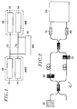
- the device is shown schematically in Figure 2 attached. It comprises a source with a photon 40, a symmetrical Mach-Zehnder interferometer 41 comprising a phase modulator 42 specific to Alice and a phase modulator 52 specific to Bob. At the output of the interferometer there are two one-photon detectors 61, 62 and a decoding and counting circuit 64.
- This device works in the following way: Alice and Bob introduce by the modulators 42 and 52, for each photon emitted by the source 40, a phase difference. Alice arbitrarily chooses which phase correspond bits 0 and 1. Bob determines the state of the bit sent by the two detectors 61, 62 following the second measurement protocol described above.
- FIG. 3 Another system is therefore used for large distances, which is represented in FIG. 3. It also comprises a source with a photon 70, a first Mach-Zehnder interferometer 80 used on transmission, with a first phase modulator 82 Alice and a second Mach-Zehnder 90 interferometer used in reception with a second Bob-specific phase modulator 92, two one-photon detectors 101, 102 and decoding and counting means 104.
- the two interferometers 80, 90 are connected by a channel 95, which is, in practice, an optical fiber.
- Each interferometer has, on one of its arms, an optical phase shifter 82, 92 for transmitting the key. It is necessary, however, that signals from both arms of the same interferometer do not interfere. It is therefore necessary to separate these two signals, either by using for example a delay between the two arms greater than the coherence length of the source (which is, in this case, pulse), or by using an accousto-optical modulator to separate Frequently, the signal propagating in one of the two arms of the interferometers.
- the device comprises a pulse source 110, a first interferometer, specific to Alice, with a first semi-transparent plate 112, a first phase modulator 114 and a second semi-transparent plate 116; it further comprises a second interferometer specific to Bob, with a third semi-transparent plate 118, a second phase modulator 120 and a fourth semi-transparent plate 122; the device further comprises a detector with a photon 124 and finally a counting and decrypting circuit 126.
- the second, 142 is the superposition of the first delayed (but not attenuated) signal pulse and the reference pulse attenuated and out of phase by Bob.
- the intensity of the second pulse, 142 therefore depends on both phase shifts introduced by Bob and Alice. It is used to transmit the encryption key.
- the last pulse, 144 is the part of the reference pulse which has been further delayed and whose intensity is constant. It will be used to determine if the line was spied.
- the object of the present invention is precisely to overcome these disadvantages.
- the modulation performed on transmission is an amplitude modulation, this amplitude having the form 1 + a cos ( ⁇ t + ⁇ A ) where a is the modulation rate and ⁇ the modulation pulse.
- a is the modulation rate and ⁇ the modulation pulse.
- the modulation ratio is preferably chosen to be less than 0.5 and for example close to 0.1.
- the method of the invention is completed by verification operations to determine whether the quantum channel has been spied by a third party.
- the sender and the recipient sacrifice some elements of their key, by comparing them publicly, to determine any errors that have been caused by the spy.
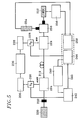
- the device shown in FIG. 5 comprises, on the transmission side, a monochromatic source 200 (constituted for example by a semiconductor laser such as a distributed feedback laser (DFB) operating at 1 ⁇ m or at 1.5 ⁇ m), an attenuator 202, a first optical modulator 204 controlled by a carrier, the latter being produced by a generator 206, the phase ⁇ A of this carrier being regulated by a phase-shifter 208.
- the modulated optical wave is transmitted on a line 210, which can to be an optical fiber. This line constitutes the quantum channel.
- the device On the reception side, the device comprises a second modulator 224, controlled by a carrier produced by a local generator 226, the phase ⁇ B of this carrier being regulated by a phase-shifter 228.
- Various electronic means are synchronized, between transmitter and receiver, firstly by a modulation frequency synchronization circuit 230, which controls the two local generators 206 and 226, and then by a synchronization circuit of the control of the phase shifts 240, which controls a first circuit 242 for controlling and storing the electrical phase shift ⁇ A imposed by the phase-shifter 208, and a second circuit 244 for controlling and storing the electrical phase-shift ⁇ B imposed by the phase-shifter 228.
- a public channel 243 is used to exchange and compare the results.
- the device further comprises a spectral filter 250, for example of the Fabry-Perot interferometer type, a single-photon detector 252 (for example an avalanche photodiode), placed behind the spectral filter 250, a multiphoton detector 254, for example of the photodiode type, a photon counter 256 connected to the one-photon detector 252 and a circuit 258 for controlling and storing the photon count.
- a spectral filter 250 for example of the Fabry-Perot interferometer type
- a single-photon detector 252 for example an avalanche photodiode
- a multiphoton detector 254 for example of the photodiode type
- a photon counter 256 connected to the one-photon detector 252 and a circuit 258 for controlling and storing the photon count.
- the light beam emitted by the source 200 is attenuated by the adjustable attenuator 202 to obtain a low output intensity but large enough to be considered as conventional.
- This attenuated beam constitutes the reference beam.
- the reference beam is modulated either in amplitude or in phase by the modulator 204.
- This periodic modulation is, in the simplest case, sinusoidal. It is produced by the local generator 206.
- Ao and ⁇ o are respectively the amplitude and the pulsation of the optical field at the input of the modulator 204.
- this amplitude modulation reveals two lateral modes at the two lateral frequencies separated by ⁇ from the initial pulse ⁇ 0.
- the amplitude of these lateral modes is Aof / 2. It is these lateral frequencies which, according to the invention, are used for quantum transmission.
- the intensity of these lateral modes must be weak enough to consider that there is only one photon. More strictly speaking, the average time separating two photons with the same pulsation must be greater than the time interval used to transmit an information bit. This is achieved by controlling the modulation amplitude.
- the code of the information bit is performed by introducing a phase shift ⁇ A in the modulation signal. This offset is produced by the phase-shifter 208 under the control of the circuit 242.
- the amplitude of the beam at the output of the first modulator 204 becomes: AT 1 ⁇ Ao ⁇ 1 + f cos ⁇ ⁇ t + ⁇ AT
- This signal is transmitted to the second modulator 224 via the optical fiber 210.
- This fiber constitutes the quantum transmission channel.
- Bob through his local generator 226, modulates the received optical signal with the same amplitude. It itself introduces a phase ⁇ B through the phase shifter 228.
- the amplitude at the output of the second modulator 224 is of the form: AT 1 ⁇ Ao ⁇ 1 + f cos ⁇ ⁇ t + ⁇ AT + f cos ⁇ ⁇ t + ⁇ B ) ⁇ Ao ( 1 + 2 f cos ⁇ ( ⁇ AT - ⁇ B ) / 2 cos ⁇ t + ⁇ B + ⁇ AT / 2
- the intensity of the lateral modes therefore depends on the phases ⁇ A and ⁇ B introduced by the transmitter and the receiver: I ⁇ 4 ⁇ Aof 2 ( cos ( ⁇ AT - ⁇ B ) / 2 cos ( ⁇ t + ⁇ B + ⁇ AT / 2 ) ) 2
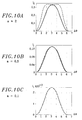
- FIGS. 6B, 6C, 6D represent the respective intensities of the lateral modes according to the respective values of the phase shifts ⁇ A and ⁇ B :
- Bob uses the spectral filter 250, which makes it possible to separate the central mode ⁇ o and the lateral modes ( ⁇ O ⁇ ⁇ ).
- the detection of the reference beam ( ⁇ O) is carried out by the conventional photodetector 254 and is necessary to confirm the presence of the transmitted bit. Detection of the lateral mode is performed by the one-photon detector 252.
- a spy If a spy (Eve) is present on the transmission channel, it will try to determine the status of the bit sent by Alice and return the same bit to Bob to not be detected. For that, he will use the same procedure and the same system as Bob. To detect her presence, Alice and Bob must sacrifice some elements of their key by comparing them publicly (to determine the errors caused by Eve).
- Table 1 concerns the transmission protocol of the key.
- Table 2 summarizes the strategy used by the sender of the key (Alice).
- Table 3 illustrates the detection of the presence of a spy.
- a device according to the invention may be in accordance with the diagram of FIG. 7, which relates to an assembly used to demonstrate the feasibility of the method.
- the device shown comprises a semiconductor laser 300, of the distributed feedback type (DFB) temperature-controlled by a circuit 302.
- the phase modulator 304 is controlled by a generator 306 whose output is amplified by an amplifier 308.
- output of the amplifier 308 is directly applied to the modulator 304, but is also applied to a phase shifter 310 controlled by a circuit 312.
- the modulator 320 of the receiver is controlled by the phase shifter 310.
- the two modulators 304 and 320 therefore work with a phase shift adjustable ⁇ .
- a spectrum analyzer 322, of the Fabry-Perot type, is controlled by a ramp generator 328.
- the analyzer 322 is followed by a detector 324 connected to an oscilloscope 326.
- FIG. 8 represents the simulation of the intensity (I) at the output of the Fabry-Perot 322 as a function of the displacement (D) of the mirrors when one of the modulators is in operation. Note the clear separation between the different modes related to a high modulation frequency in front of the width spectral peaks of Fabry-Perot transmission (respectively 300 MHz and 16 MHz).
- the mode of order 0 contains, on average, about thirty photons
- the first order contains on average 0.1 photon (to have a low probability to have more than one photon in this mode) .
- FIG. 9 shows the intensity ratio (RI) between the central mode and the first two lateral modes as a function of the modulation amplitude a .
- This ratio is defined by the quantity [J 1 (a) / J o (a)] where J 1 () and J o () are the Bessel functions of order 1 and 0 and have the amplitude of modulation.
- J 1 () and J o () are the Bessel functions of order 1 and 0 and have the amplitude of modulation.
- This figure shows that the modulation rate must be low, more exactly less than or equal to 0.1 (in reduced unit). We can notice that at low modulation rate, the intensity of other modes becomes negligible (1.5.10 6 times smaller than the order 0).
Landscapes
- Engineering & Computer Science (AREA)
- Physics & Mathematics (AREA)
- Electromagnetism (AREA)
- Theoretical Computer Science (AREA)
- Computer Security & Cryptography (AREA)
- Computer Networks & Wireless Communication (AREA)
- Signal Processing (AREA)
- Optical Communication System (AREA)
Claims (7)
- Verfahren zur Schlüsselverteilung mittels Quanten-Kryptographie, bei dem:- ein Absender eine Sequenz von Photonen sendet, indem er für jedes Photon einen Zustand aus zwei festgesetzten Zuständen zufallsbedingt wählt, in einer Weise, dass jedes Photon somit einen Code für ein Informationsbit bildet,- ein Empfänger die Photonen detektiert, indem er eine Messbasis aus zwei festgesetzten Basen zufallsbedingt wählt,- der Empfänger dem Absender über einen öffentlichen Kanal angibt, welche Photonen er detektiert hat, aber ohne zu enthüllen, welche Basis er benutzt hat,wobei der Absender und der Empfänger die Bit, für welche die Photonen detektiert wurden, in einer Weise berücksichtigen, als ob sie einen Kryptographie-Schlüssel zwischen ihnen bilden, wobei dieses Verfahren dadurch gekennzeichnet ist, dass:A) der Absender:a) ein Lichtbündel verursacht, das eine bestimmte Pulsation (ωo) und eine bestimmte Intensität aufweist,b) ein erstes elektrisches Modulationssignal erzeugt,c) diesem ersten elektrischen Modulationssignal eine erste Phase (ΦA) gibt, die zufallsbedingt aus zwei festgesetzten Werten gewählt wird, wobei der Code jedes Bits auf diese Weise durch diese erste Phase (ΦA) bestimmt wird,d) das Lichtbündel durch dieses erste elektrische Signal moduliert, wobei diese Modulation im modulierten Lichtbündel einen zentralen Mode (ωo) und mindestens zwei seitliche Moden (ωo ± Ω) erscheinen lässt,e) die Intensität des Lichtbündels derart dämpft, dass die Intensität der seitlichen Moden schwach genug ist, um nur ein einziges Photon in den seitlichen Moden bestehen zu lassen, wobei die den Informationsbit, welche den Kryptographie-Schlüssel bilden sollen, zugeordneten Photonen somit die in den seitlichen Moden und nicht im zentralen Mode übertragenen Photonen sind.B) der Empfänger:a) ein zweites elektrisches Modulationssignal in Synchronisation mit dem ersten elektrischen Modulationssignal, das beim Senden benutzt wurde, erzeugt,b) dem zweiten elektrischen Signal eine zweite Phase (ΦB) gibt, die zufallsbedingt aus zwei festgesetzten Werten gewählt wird, wobei sich diese zwei Werte von den zwei festgesetzten Werten, die beim Senden für die erste Phase (ΦA) gewählt werden, unterscheiden,c) das vom zweiten elektrischen Signal empfangene Lichtbündel moduliert,d) den empfangenen zentralen Mode und die seitlichen Moden optisch trennt,e) in einem der seitlichen Moden die Anwesenheit eines Photons detektiert, wobei diese Detektion von der Phasendifferenz (φ) zwischen der vom Absender gewählten ersten Phasenverschiebung (ΦA) und der vom Empfänger gewählten zweiten Phasenverschiebung (ΦB) abhängt,f) dem Absender über den öffentlichen Kanal angibt, welche Photonen er detektiert hat, aber ohne die Werte der zweiten Phasenverschiebung (ΦB), die er benutzt hat, zu enthüllen,wobei der Absender und der Empfänger dann als Kryptographie-Schlüssel die Gesamtheit der den detektierten Photonen entsprechenden Bit einbehalten.
- Verfahren nach Anspruch 1, bei dem die Modulation eine Amplituden- oder Frequenzmodulation mit einem bestimmten Modulationsgrad (a) ist.
- Verfahren nach Anspruch 2, bei dem der Modulationsgrad etwa 0,5 unterschreitet.
- Verfahren nach Anspruch 3, bei dem der Modulationsgrad in der Nähe von 0,1 liegt.
- Vorrichtung für die Ausführung des Verfahrens nach Anspruch 1, dadurch gekennzeichnet, dass sie umfasst:A) absenderseitig:a) eine Leuchtquelle (200, 300), die ein Lichtbündel erzeugen kann, das eine bestimmte Pulsation (ωo) und eine bestimmte Intensität aufweist,b) Mittel (206, 306), um ein erstes elektrisches Modulationssignal zu erzeugen,c) Mittel (208, 308), um diesem ersten elektrischen Modulationssignal eine erste Phase (ΦA) zu geben, die zufallsbedingt aus zwei festgesetzten Werten gewählt wird, wobei der Code jedes Bits somit durch diese erste Phase (ΦA) bestimmt wird,d) Mittel (204, 304), um das Lichtbündel durch dieses erste elektrische Signal zu modulieren, wobei diese Modulation im modulierten Lichtbündel einen zentralen Mode (ωo) und mindestens zwei seitliche Moden (ωo ± Ω) erscheinen lässt,e) einen Dämpfer (202) der Intensität des Lichtbündels, damit die Intensität der seitlichen Moden schwach genug ist, um nur ein einziges Photon in den seitlichen Moden bestehen zu lassen, wobei die den Informationsbit, welche den Kryptographie-Schlüssel bilden sollen, zugeordneten Photonen somit die in den seitlichen Moden und nicht im zentralen Mode übertragenen Photonen sind,B) empfängerseitig:a) Mittel (226), um ein zweites elektrisches Modulationssignal in Synchronisation mit dem ersten elektrischen Modulationssignal, das beim Senden benutzt wird, zu erzeugen,b) Mittel (228, 310, 312), um dem zweiten elektrischen Signal eine zweite Phase (ΦB) zu geben, die zufallsbedingt aus zwei festgesetzten Werten gewählt wird, wobei sich diese zwei Werte von den zwei festgesetzten Werten, die beim Senden für die ersten Phase (ΦA) gewählt werden, unterscheiden,c) Mittel (224, 320), um das empfangene Lichtbündel durch das zweite elektrische Signal zu modulieren,d) einen Analysator (250, 322), um den empfangenen zentralen Mode und die seitlichen Moden optisch zu trennen,e) einen Photodetektor (252, 324), der einen der seitlichen Moden empfängt, wobei das von diesem Photodetektor gelieferte Signal von der Phasendifferenz (Φ) zwischen der vom Absender gewählten ersten Phasenverschiebung (ΦA) und der vom Empfänger gewählten zweiten Phasenverschiebung (ΦB) abhängt,f) Mittel (243), um dem Absender über einen öffentlichen Kanal anzugeben, welche Photonen detektiert wurden, aber ohne die benutzten Werte der zweiten Phasenverschiebung (ΦB) zu enthüllen,und absender- und empfängerseitig Mittel (242, 244), um alle Bit, die den detektierten Photonen entsprechen, als Kryptographie-Schlüssel einzubehalten.
- Vorrichtung nach Anspruch 5, bei der die Leuchtquelle (200, 300) ein Halbleiterlaser ist.
- Vorrichtung nach Anspruch 5, umfassend Mittel zur mehrfachen Schlüsselverteilung mittels Kryptographie durch Nutzung der Wellenlängenmultiplexmittel.
Applications Claiming Priority (2)
| Application Number | Priority Date | Filing Date | Title |
|---|---|---|---|
| FR9705573 | 1997-05-06 | ||
| FR9705573A FR2763193B1 (fr) | 1997-05-06 | 1997-05-06 | Procede et dispositif de distribution quantique de cle de cryptage |
Publications (2)
| Publication Number | Publication Date |
|---|---|
| EP0877508A1 EP0877508A1 (de) | 1998-11-11 |
| EP0877508B1 true EP0877508B1 (de) | 2007-08-01 |
Family
ID=9506628
Family Applications (1)
| Application Number | Title | Priority Date | Filing Date |
|---|---|---|---|
| EP98401079A Expired - Lifetime EP0877508B1 (de) | 1997-05-06 | 1998-05-04 | Verfahren und Vorrichtung zur Schlüsselverteilung mittels Quanten-Kryptographie |
Country Status (4)
| Country | Link |
|---|---|
| US (1) | US6272224B1 (de) |
| EP (1) | EP0877508B1 (de) |
| DE (1) | DE69838159D1 (de) |
| FR (1) | FR2763193B1 (de) |
Families Citing this family (58)
| Publication number | Priority date | Publication date | Assignee | Title |
|---|---|---|---|---|
| JP4038783B2 (ja) * | 1998-09-24 | 2008-01-30 | 独立行政法人科学技術振興機構 | 量子暗号通信システム及び量子暗号通信方法 |
| DE10009209A1 (de) * | 2000-02-26 | 2001-09-06 | Deutsche Telekom Ag | Vorrichtung zur Erzeugung, Addition und Subtraktion digitaler Folgen optischer Pulse und Verfahren zur sicheren Übertragung von Nachrichten |
| KR100327494B1 (ko) * | 2000-03-24 | 2002-03-15 | 윤종용 | 다중 접근 방식을 이용한 보안 통신 시스템에서의 키 동의방법 |
| FR2816780B1 (fr) * | 2000-11-10 | 2003-01-31 | Thomson Csf | Procede et systeme de transmission par cryptographie quantique |
| FR2816772B1 (fr) * | 2000-11-10 | 2003-01-31 | Thomson Csf | Procede et systeme de transmission par cryptographie quantique |
| FR2818061B1 (fr) * | 2000-12-12 | 2003-03-28 | France Telecom | Systeme pour la transmission optique securisee de code binaire |
| US7184555B2 (en) * | 2001-04-11 | 2007-02-27 | Magiq Technologies, Inc. | Quantum computation |
| AU2002255801A1 (en) * | 2001-04-11 | 2002-10-28 | Magiq Technologies, Inc. | Polarization to phase converter |
| WO2002089396A1 (en) * | 2001-05-01 | 2002-11-07 | Magiq Technologies, Inc. | Quantum key system and method |
| US7113967B2 (en) | 2001-05-29 | 2006-09-26 | Magiq Technologies, Inc | Efficient quantum computing operations |
| AU2002362018A1 (en) * | 2001-12-21 | 2003-07-24 | Magiq Technologies, Inc. | Decoupling error correction from privacy amplification in quantum key distribution |
| JP4462806B2 (ja) * | 2002-02-22 | 2010-05-12 | 日本電気株式会社 | 量子暗号鍵配布システム |
| US7403623B2 (en) * | 2002-07-05 | 2008-07-22 | Universite Libre De Bruxelles | High-rate quantum key distribution scheme relying on continuously phase and amplitude-modulated coherent light pulses |
| US7333611B1 (en) | 2002-09-27 | 2008-02-19 | Northwestern University | Ultra-secure, ultra-efficient cryptographic system |
| US20060222180A1 (en) * | 2002-10-15 | 2006-10-05 | Elliott Brig B | Chip-scale transmitter for quantum cryptography |
| US20060018475A1 (en) * | 2003-02-07 | 2006-01-26 | Magiq Technologies, Inc. | Kd systems with robust timing |
| US7227955B2 (en) * | 2003-02-07 | 2007-06-05 | Magiq Technologies, Inc. | Single-photon watch dog detector for folded quantum key distribution system |
| US7609382B2 (en) * | 2003-05-23 | 2009-10-27 | General Dynamics Advanced Information System, Inc, | System and method of detecting entangled photons |
| US7539308B2 (en) * | 2003-05-23 | 2009-05-26 | General Dynamics Advanced Information Systems, Inc. | Quantum steganography |
| GB2404103B (en) | 2003-07-15 | 2005-06-29 | Toshiba Res Europ Ltd | A quantum communication system |
| US7847234B2 (en) | 2003-08-06 | 2010-12-07 | The United States Of America As Represented By The Secretary Of The Army | Method and system for observing a subject at a first location based upon quantum properties measured at a second location |
| US8242428B2 (en) * | 2007-12-06 | 2012-08-14 | The United States Of America As Represented By The Secretary Of The Army | Method and system for lidar using spatial information from a light source in combination with nonspatial information influenced by the subject to derive an image |
| US7536012B1 (en) | 2003-08-06 | 2009-05-19 | The United States Of America As Represented By The Secretary Of The Army | Entangled quantum communications and quantum imaging |
| GB2405294B (en) * | 2003-08-18 | 2006-08-09 | Toshiba Res Europ Ltd | A quantum communication system and a receiver for a quantum communication system |
| US7831048B2 (en) * | 2003-12-17 | 2010-11-09 | General Dynamics Advanced Information Systems, Inc. | Secure quantum key distribution using entangled photons |
| US20080144823A1 (en) * | 2004-07-12 | 2008-06-19 | Mitsubishi Denki Kabushiki Kaisha | Photon Detecting Device and Optical Communication System |
| WO2006011215A1 (ja) * | 2004-07-29 | 2006-02-02 | Mitsubishi Denki Kabushiki Kaisha | 場所状態管理システム、無線タグ読取装置および管理装置 |
| US7822342B1 (en) | 2004-11-15 | 2010-10-26 | The United States Of America As Represented By The Secretary Of The Navy | Secure quantum optical communications system and method |
| US7706694B2 (en) * | 2005-07-25 | 2010-04-27 | General Dynamics Advanced Information Systems, Inc. | Processor for entangled complex signals |
| FR2889320B1 (fr) * | 2005-07-27 | 2007-10-26 | Smartquantum Sa | Systeme de transmission optique et dispositif de reception d'un signal optique |
| GB2430124B (en) * | 2005-09-09 | 2008-01-09 | Toshiba Res Europ Ltd | Quantum communication system |
| US7809143B2 (en) * | 2005-10-24 | 2010-10-05 | Magiq Technologies, Inc. | QKD system with synchronization channel verification |
| JP4829628B2 (ja) * | 2005-10-31 | 2011-12-07 | 富士通株式会社 | 暗号化方法,暗号復号化方法,暗号化装置,暗号復号化装置および通信システム |
| US20070130455A1 (en) * | 2005-12-06 | 2007-06-07 | Elliott Brig B | Series encryption in a quantum cryptographic system |
| US20070133798A1 (en) * | 2005-12-14 | 2007-06-14 | Elliott Brig B | Quantum cryptography on a multi-drop optical network |
| US8082443B2 (en) * | 2006-01-09 | 2011-12-20 | Bbnt Solutions Llc. | Pedigrees for quantum cryptography |
| US7248695B1 (en) * | 2006-02-10 | 2007-07-24 | Magiq Technologies, Inc. | Systems and methods for transmitting quantum and classical signals over an optical network |
| US20070291811A1 (en) * | 2006-05-26 | 2007-12-20 | Conti Ralph S | Entangled Photon Source |
| GB2441364B (en) * | 2006-08-31 | 2009-02-11 | Toshiba Res Europ Ltd | A quantum communication system and method |
| FR2906424B1 (fr) * | 2006-09-25 | 2008-11-28 | Centre Nat Rech Scient | Systeme et procede pour la transmission securisee de code binaire par codage en phase et en intensite |
| US8811763B2 (en) | 2007-12-06 | 2014-08-19 | The United States Of America As Represented By The Secretary Of The Army | Method and system for producing image frames using quantum properties |
| JP2011130120A (ja) * | 2009-12-16 | 2011-06-30 | Sony Corp | 量子公開鍵暗号システム、鍵生成装置、暗号化装置、復号装置、鍵生成方法、暗号化方法、及び復号方法 |
| JP5682212B2 (ja) * | 2010-10-06 | 2015-03-11 | ソニー株式会社 | 量子暗号通信装置と量子暗号通信方法および量子暗号通信システム |
| RU2454810C1 (ru) * | 2010-11-24 | 2012-06-27 | Федеральное государственное бюджетное образовательное учреждение высшего профессионального образования "Санкт-Петербургский национальный исследовательский университет информационных технологий, механики и оптики" ("НИУ ИТМО") | Устройство квантовой рассылки криптографического ключа на поднесущей частоте модулированного излучения |
| US9184912B2 (en) * | 2012-04-17 | 2015-11-10 | The Boeing Company | Secure quantum authentication system |
| GB2514134B (en) * | 2013-05-14 | 2016-05-25 | Toshiba Res Europe Ltd | A signal manipulator for a quantum communication system |
| CN106411521B (zh) * | 2015-07-31 | 2020-02-18 | 阿里巴巴集团控股有限公司 | 用于量子密钥分发过程的身份认证方法、装置及系统 |
| CN105337730B (zh) * | 2015-11-19 | 2018-08-24 | 山西大学 | 基于相位编码qkd系统的单光子偏振控制方法及装置 |
| RU2692431C1 (ru) * | 2018-07-03 | 2019-06-24 | Федеральное государственное образовательное учреждение высшего образования "Казанский национальный исследовательский технический университет им. А.Н. Туполева - КАИ" | Устройство квантовой рассылки криптографического ключа с частотным кодированием |
| RU2747164C1 (ru) * | 2019-11-12 | 2021-04-28 | Общество с ограниченной ответственностью "СМАРТС-Кванттелеком" | Устройство квантовой рассылки ключа на боковых частотах, устойчивое к поляризационным искажениям сигнала в волоконно-оптических линиях связи |
| RU2750810C1 (ru) * | 2020-01-22 | 2021-07-05 | Общество с ограниченной ответственностью "СМАРТС-Кванттелеком" | Устройство квантовой коммуникации на боковых частотах с регистрацией излучения на центральной частоте |
| RU2744509C1 (ru) * | 2020-01-22 | 2021-03-11 | Общество с ограниченной ответственностью "Кванттелеком" | Устройство квантовой коммуникации на боковых частотах с увеличенным дискретным набором фаз модулирующих сигналов |
| RU2758711C1 (ru) * | 2020-09-15 | 2021-11-01 | Общество с ограниченной ответственностью "СМАРТС-Кванттелеком" | Устройство квантовой рассылки симметричной битовой последовательности на поднесущей частоте модулированного излучения с гетеродинным методом приема |
| RU2758709C1 (ru) * | 2020-09-15 | 2021-11-01 | Общество с ограниченной ответственностью "СМАРТС-Кванттелеком" | Устройство квантовой рассылки симметричной битовой последовательности на поднесущей частоте модулированного излучения с гомодинным методом приема |
| RU2758708C1 (ru) * | 2020-09-15 | 2021-11-01 | Общество с ограниченной ответственностью "СМАРТС-Кванттелеком" | Устройство квантовой рассылки симметричной битовой последовательности на поднесущей частоте модулированного излучения с двойным гомодинным методом приема |
| CN112461380B (zh) * | 2020-10-15 | 2021-09-24 | 国开启科量子技术(北京)有限公司 | 一种脉冲光相位随机性检测装置及方法 |
| CN114499685B (zh) * | 2022-01-28 | 2023-10-20 | 中国科学技术大学 | 信号处理方法、发射端系统、电子设备及存储介质 |
| CN114584224B (zh) * | 2022-04-28 | 2022-08-05 | 杭州慧明量子通信技术有限公司 | 一种量子密钥分发相位编码装置 |
Family Cites Families (10)
| Publication number | Priority date | Publication date | Assignee | Title |
|---|---|---|---|---|
| US5243649A (en) * | 1992-09-29 | 1993-09-07 | The Johns Hopkins University | Apparatus and method for quantum mechanical encryption for the transmission of secure communications |
| DE69309496T2 (de) * | 1992-12-24 | 1997-08-07 | British Telecomm | System und verfahren zur schluesselverteilung unter verwendung von quanten-kryptographie |
| US5339182A (en) * | 1993-02-19 | 1994-08-16 | California Institute Of Technology | Method and apparatus for quantum communication employing nonclassical correlations of quadrature-phase amplitudes |
| US5307410A (en) * | 1993-05-25 | 1994-04-26 | International Business Machines Corporation | Interferometric quantum cryptographic key distribution system |
| EP0739559B1 (de) * | 1993-09-09 | 2003-04-09 | BRITISH TELECOMMUNICATIONS public limited company | Verfahren zur schlusselverteilung unter verwendung von quanten-kryptographie |
| GB9320793D0 (en) * | 1993-10-08 | 1993-12-08 | Secr Defence | Cryptographic receiver |
| US5515438A (en) * | 1993-11-24 | 1996-05-07 | International Business Machines Corporation | Quantum key distribution using non-orthogonal macroscopic signals |
| EP0776558B1 (de) * | 1994-08-18 | 2001-06-27 | BRITISH TELECOMMUNICATIONS public limited company | Quantenkryptographie |
| US5953421A (en) * | 1995-08-16 | 1999-09-14 | British Telecommunications Public Limited Company | Quantum cryptography |
| US5966224A (en) * | 1997-05-20 | 1999-10-12 | The Regents Of The University Of California | Secure communications with low-orbit spacecraft using quantum cryptography |
-
1997
- 1997-05-06 FR FR9705573A patent/FR2763193B1/fr not_active Expired - Fee Related
-
1998
- 1998-04-21 US US09/063,413 patent/US6272224B1/en not_active Expired - Fee Related
- 1998-05-04 EP EP98401079A patent/EP0877508B1/de not_active Expired - Lifetime
- 1998-05-04 DE DE69838159T patent/DE69838159D1/de not_active Expired - Lifetime
Non-Patent Citations (1)
| Title |
|---|
| None * |
Also Published As
| Publication number | Publication date |
|---|---|
| US6272224B1 (en) | 2001-08-07 |
| DE69838159D1 (de) | 2007-09-13 |
| EP0877508A1 (de) | 1998-11-11 |
| FR2763193B1 (fr) | 1999-06-18 |
| FR2763193A1 (fr) | 1998-11-13 |
Similar Documents
| Publication | Publication Date | Title |
|---|---|---|
| EP0877508B1 (de) | Verfahren und Vorrichtung zur Schlüsselverteilung mittels Quanten-Kryptographie | |
| EP1825633B1 (de) | Kontinuierlich variables system zur verschlüsselungsschlüssel-quantendistribution | |
| EP1342337B1 (de) | Vorrichtung zur gesicherten optischen übertragung eines binären kodes | |
| US8374350B2 (en) | Quantum communication system | |
| EP0963064B1 (de) | Anordnung zum Senden und Empfangen eines auf Basis von deterministischem Chaos verschlüsselten Signals | |
| US20050190922A1 (en) | Secure use of a single single-photon detector in a QKD system | |
| GB2405294A (en) | Receiver for a quantum cryptography communication system | |
| FR2920550A1 (fr) | Emetteur optique et son procede de commande. | |
| WO2013112351A2 (en) | Systems and methods for telecommunication using high-dimensional temporal quantum key distribution | |
| JP2000511016A (ja) | 偏波に感応しない量子暗号用の方法および装置 | |
| US11223419B1 (en) | Optical system and method | |
| Merolla et al. | Quantum cryptographic device using single-photon phase modulation | |
| EP2067298B1 (de) | System und verfahren zur sicheren übertragung eines binären codes durch phasen- und intensitätskodierung | |
| WO2007012730A2 (fr) | Système de transmission optique et dispositif de réception d'un signal optique | |
| WO2023001721A1 (fr) | Système de communication quantique par photons intriqués | |
| WO2021043891A1 (fr) | Procede de transmission securisee de sequences d'etats quantiques entre plusieurs participants en ligne sur un canal de communication quantique | |
| WO2023232937A1 (fr) | Systeme et procede de determination de cles de cryptage utilisant l'encodage de phase d'un signal | |
| Francesconi et al. | Scalable Implementation of Temporal and Phase Encoding QKD with Phase‐Randomized States | |
| Curtacci et al. | Performance analysis of different multi-user optical passive networks for quantum cryptography applications | |
| Kumavor et al. | Demonstration of a six-user quantum key distribution network on a bus architecture | |
| WO2023218341A1 (en) | Method for remote generation of two arbitrary-length identical random cryptographic keys with the device-independent security using entangled multiphoton sources of quantum light | |
| Agnolini | Contribution à l'étude et à la réalisation d'un système de distribution quantique de clef par codage en phase | |
| WO2006108772A1 (fr) | Systeme de distribution quantique de cle par codage temporel |
Legal Events
| Date | Code | Title | Description |
|---|---|---|---|
| PUAI | Public reference made under article 153(3) epc to a published international application that has entered the european phase |
Free format text: ORIGINAL CODE: 0009012 |
|
| AK | Designated contracting states |
Kind code of ref document: A1 Designated state(s): DE GB |
|
| AX | Request for extension of the european patent |
Free format text: AL;LT;LV;MK;RO;SI |
|
| 17P | Request for examination filed |
Effective date: 19990417 |
|
| AKX | Designation fees paid |
Free format text: DE GB |
|
| GRAP | Despatch of communication of intention to grant a patent |
Free format text: ORIGINAL CODE: EPIDOSNIGR1 |
|
| GRAS | Grant fee paid |
Free format text: ORIGINAL CODE: EPIDOSNIGR3 |
|
| GRAA | (expected) grant |
Free format text: ORIGINAL CODE: 0009210 |
|
| AK | Designated contracting states |
Kind code of ref document: B1 Designated state(s): DE GB |
|
| REG | Reference to a national code |
Ref country code: GB Ref legal event code: FG4D Free format text: NOT ENGLISH |
|
| REF | Corresponds to: |
Ref document number: 69838159 Country of ref document: DE Date of ref document: 20070913 Kind code of ref document: P |
|
| GBT | Gb: translation of ep patent filed (gb section 77(6)(a)/1977) |
Effective date: 20070905 |
|
| PLBE | No opposition filed within time limit |
Free format text: ORIGINAL CODE: 0009261 |
|
| STAA | Information on the status of an ep patent application or granted ep patent |
Free format text: STATUS: NO OPPOSITION FILED WITHIN TIME LIMIT |
|
| 26N | No opposition filed |
Effective date: 20080506 |
|
| PG25 | Lapsed in a contracting state [announced via postgrant information from national office to epo] |
Ref country code: DE Free format text: LAPSE BECAUSE OF FAILURE TO SUBMIT A TRANSLATION OF THE DESCRIPTION OR TO PAY THE FEE WITHIN THE PRESCRIBED TIME-LIMIT Effective date: 20071103 |
|
| PGFP | Annual fee paid to national office [announced via postgrant information from national office to epo] |
Ref country code: GB Payment date: 20100429 Year of fee payment: 13 |
|
| GBPC | Gb: european patent ceased through non-payment of renewal fee |
Effective date: 20110504 |
|
| PG25 | Lapsed in a contracting state [announced via postgrant information from national office to epo] |
Ref country code: GB Free format text: LAPSE BECAUSE OF NON-PAYMENT OF DUE FEES Effective date: 20110504 |