EP4407739A1 - Jelly-roll-elektrodenanordnung, herstellungsverfahren für jelly-roll-elektrodenanordnung und sekundärbatterie damit - Google Patents
Jelly-roll-elektrodenanordnung, herstellungsverfahren für jelly-roll-elektrodenanordnung und sekundärbatterie damit Download PDFInfo
- Publication number
- EP4407739A1 EP4407739A1 EP23873049.3A EP23873049A EP4407739A1 EP 4407739 A1 EP4407739 A1 EP 4407739A1 EP 23873049 A EP23873049 A EP 23873049A EP 4407739 A1 EP4407739 A1 EP 4407739A1
- Authority
- EP
- European Patent Office
- Prior art keywords
- electrode
- jelly
- swelling tape
- roll type
- electrode assembly
- Prior art date
- Legal status (The legal status is an assumption and is not a legal conclusion. Google has not performed a legal analysis and makes no representation as to the accuracy of the status listed.)
- Pending
Links
Images


Classifications
-
- H—ELECTRICITY
- H01—ELECTRIC ELEMENTS
- H01M—PROCESSES OR MEANS, e.g. BATTERIES, FOR THE DIRECT CONVERSION OF CHEMICAL ENERGY INTO ELECTRICAL ENERGY
- H01M10/00—Secondary cells; Manufacture thereof
- H01M10/04—Construction or manufacture in general
-
- H—ELECTRICITY
- H01—ELECTRIC ELEMENTS
- H01M—PROCESSES OR MEANS, e.g. BATTERIES, FOR THE DIRECT CONVERSION OF CHEMICAL ENERGY INTO ELECTRICAL ENERGY
- H01M10/00—Secondary cells; Manufacture thereof
- H01M10/04—Construction or manufacture in general
- H01M10/0431—Cells with wound or folded electrodes
-
- H—ELECTRICITY
- H01—ELECTRIC ELEMENTS
- H01M—PROCESSES OR MEANS, e.g. BATTERIES, FOR THE DIRECT CONVERSION OF CHEMICAL ENERGY INTO ELECTRICAL ENERGY
- H01M10/00—Secondary cells; Manufacture thereof
- H01M10/05—Accumulators with non-aqueous electrolyte
- H01M10/052—Li-accumulators
- H01M10/0525—Rocking-chair batteries, i.e. batteries with lithium insertion or intercalation in both electrodes; Lithium-ion batteries
-
- H—ELECTRICITY
- H01—ELECTRIC ELEMENTS
- H01M—PROCESSES OR MEANS, e.g. BATTERIES, FOR THE DIRECT CONVERSION OF CHEMICAL ENERGY INTO ELECTRICAL ENERGY
- H01M10/00—Secondary cells; Manufacture thereof
- H01M10/05—Accumulators with non-aqueous electrolyte
- H01M10/056—Accumulators with non-aqueous electrolyte characterised by the materials used as electrolytes, e.g. mixed inorganic/organic electrolytes
- H01M10/0564—Accumulators with non-aqueous electrolyte characterised by the materials used as electrolytes, e.g. mixed inorganic/organic electrolytes the electrolyte being constituted of organic materials only
- H01M10/0566—Liquid materials
- H01M10/0569—Liquid materials characterised by the solvents
-
- H—ELECTRICITY
- H01—ELECTRIC ELEMENTS
- H01M—PROCESSES OR MEANS, e.g. BATTERIES, FOR THE DIRECT CONVERSION OF CHEMICAL ENERGY INTO ELECTRICAL ENERGY
- H01M10/00—Secondary cells; Manufacture thereof
- H01M10/05—Accumulators with non-aqueous electrolyte
- H01M10/058—Construction or manufacture
- H01M10/0587—Construction or manufacture of accumulators having only wound construction elements, i.e. wound positive electrodes, wound negative electrodes and wound separators
-
- H—ELECTRICITY
- H01—ELECTRIC ELEMENTS
- H01M—PROCESSES OR MEANS, e.g. BATTERIES, FOR THE DIRECT CONVERSION OF CHEMICAL ENERGY INTO ELECTRICAL ENERGY
- H01M50/00—Constructional details or processes of manufacture of the non-active parts of electrochemical cells other than fuel cells, e.g. hybrid cells
- H01M50/10—Primary casings; Jackets or wrappings
- H01M50/102—Primary casings; Jackets or wrappings characterised by their shape or physical structure
- H01M50/107—Primary casings; Jackets or wrappings characterised by their shape or physical structure having curved cross-section, e.g. round or elliptic
-
- H—ELECTRICITY
- H01—ELECTRIC ELEMENTS
- H01M—PROCESSES OR MEANS, e.g. BATTERIES, FOR THE DIRECT CONVERSION OF CHEMICAL ENERGY INTO ELECTRICAL ENERGY
- H01M50/00—Constructional details or processes of manufacture of the non-active parts of electrochemical cells other than fuel cells, e.g. hybrid cells
- H01M50/40—Separators; Membranes; Diaphragms; Spacing elements inside cells
- H01M50/471—Spacing elements inside cells other than separators, membranes or diaphragms; Manufacturing processes thereof
- H01M50/474—Spacing elements inside cells other than separators, membranes or diaphragms; Manufacturing processes thereof characterised by their position inside the cells
-
- H—ELECTRICITY
- H01—ELECTRIC ELEMENTS
- H01M—PROCESSES OR MEANS, e.g. BATTERIES, FOR THE DIRECT CONVERSION OF CHEMICAL ENERGY INTO ELECTRICAL ENERGY
- H01M50/00—Constructional details or processes of manufacture of the non-active parts of electrochemical cells other than fuel cells, e.g. hybrid cells
- H01M50/40—Separators; Membranes; Diaphragms; Spacing elements inside cells
- H01M50/471—Spacing elements inside cells other than separators, membranes or diaphragms; Manufacturing processes thereof
- H01M50/477—Spacing elements inside cells other than separators, membranes or diaphragms; Manufacturing processes thereof characterised by their shape
-
- H—ELECTRICITY
- H01—ELECTRIC ELEMENTS
- H01M—PROCESSES OR MEANS, e.g. BATTERIES, FOR THE DIRECT CONVERSION OF CHEMICAL ENERGY INTO ELECTRICAL ENERGY
- H01M50/00—Constructional details or processes of manufacture of the non-active parts of electrochemical cells other than fuel cells, e.g. hybrid cells
- H01M50/40—Separators; Membranes; Diaphragms; Spacing elements inside cells
- H01M50/471—Spacing elements inside cells other than separators, membranes or diaphragms; Manufacturing processes thereof
- H01M50/48—Spacing elements inside cells other than separators, membranes or diaphragms; Manufacturing processes thereof characterised by the material
- H01M50/486—Organic material
-
- H—ELECTRICITY
- H01—ELECTRIC ELEMENTS
- H01M—PROCESSES OR MEANS, e.g. BATTERIES, FOR THE DIRECT CONVERSION OF CHEMICAL ENERGY INTO ELECTRICAL ENERGY
- H01M50/00—Constructional details or processes of manufacture of the non-active parts of electrochemical cells other than fuel cells, e.g. hybrid cells
- H01M50/40—Separators; Membranes; Diaphragms; Spacing elements inside cells
- H01M50/489—Separators, membranes, diaphragms or spacing elements inside the cells, characterised by their physical properties, e.g. swelling degree, hydrophilicity or shut down properties
-
- H—ELECTRICITY
- H01—ELECTRIC ELEMENTS
- H01M—PROCESSES OR MEANS, e.g. BATTERIES, FOR THE DIRECT CONVERSION OF CHEMICAL ENERGY INTO ELECTRICAL ENERGY
- H01M50/00—Constructional details or processes of manufacture of the non-active parts of electrochemical cells other than fuel cells, e.g. hybrid cells
- H01M50/50—Current conducting connections for cells or batteries
- H01M50/572—Means for preventing undesired use or discharge
- H01M50/584—Means for preventing undesired use or discharge for preventing incorrect connections inside or outside the batteries
- H01M50/586—Means for preventing undesired use or discharge for preventing incorrect connections inside or outside the batteries inside the batteries, e.g. incorrect connections of electrodes
-
- H—ELECTRICITY
- H01—ELECTRIC ELEMENTS
- H01M—PROCESSES OR MEANS, e.g. BATTERIES, FOR THE DIRECT CONVERSION OF CHEMICAL ENERGY INTO ELECTRICAL ENERGY
- H01M50/00—Constructional details or processes of manufacture of the non-active parts of electrochemical cells other than fuel cells, e.g. hybrid cells
- H01M50/50—Current conducting connections for cells or batteries
- H01M50/572—Means for preventing undesired use or discharge
- H01M50/584—Means for preventing undesired use or discharge for preventing incorrect connections inside or outside the batteries
- H01M50/59—Means for preventing undesired use or discharge for preventing incorrect connections inside or outside the batteries characterised by the protection means
- H01M50/595—Tapes
-
- H—ELECTRICITY
- H01—ELECTRIC ELEMENTS
- H01M—PROCESSES OR MEANS, e.g. BATTERIES, FOR THE DIRECT CONVERSION OF CHEMICAL ENERGY INTO ELECTRICAL ENERGY
- H01M2300/00—Electrolytes
- H01M2300/0017—Non-aqueous electrolytes
- H01M2300/0025—Organic electrolyte
- H01M2300/0028—Organic electrolyte characterised by the solvent
- H01M2300/0037—Mixture of solvents
- H01M2300/004—Three solvents
-
- Y—GENERAL TAGGING OF NEW TECHNOLOGICAL DEVELOPMENTS; GENERAL TAGGING OF CROSS-SECTIONAL TECHNOLOGIES SPANNING OVER SEVERAL SECTIONS OF THE IPC; TECHNICAL SUBJECTS COVERED BY FORMER USPC CROSS-REFERENCE ART COLLECTIONS [XRACs] AND DIGESTS
- Y02—TECHNOLOGIES OR APPLICATIONS FOR MITIGATION OR ADAPTATION AGAINST CLIMATE CHANGE
- Y02E—REDUCTION OF GREENHOUSE GAS [GHG] EMISSIONS, RELATED TO ENERGY GENERATION, TRANSMISSION OR DISTRIBUTION
- Y02E60/00—Enabling technologies; Technologies with a potential or indirect contribution to GHG emissions mitigation
- Y02E60/10—Energy storage using batteries
-
- Y—GENERAL TAGGING OF NEW TECHNOLOGICAL DEVELOPMENTS; GENERAL TAGGING OF CROSS-SECTIONAL TECHNOLOGIES SPANNING OVER SEVERAL SECTIONS OF THE IPC; TECHNICAL SUBJECTS COVERED BY FORMER USPC CROSS-REFERENCE ART COLLECTIONS [XRACs] AND DIGESTS
- Y02—TECHNOLOGIES OR APPLICATIONS FOR MITIGATION OR ADAPTATION AGAINST CLIMATE CHANGE
- Y02P—CLIMATE CHANGE MITIGATION TECHNOLOGIES IN THE PRODUCTION OR PROCESSING OF GOODS
- Y02P70/00—Climate change mitigation technologies in the production process for final industrial or consumer products
- Y02P70/50—Manufacturing or production processes characterised by the final manufactured product
Definitions
- the present invention relates to a jelly-roll type electrode assembly, a method for manufacturing a jelly-roll type electrode assembly, and a secondary battery including the same, and more particularly, to a jelly-roll type electrode assembly including a swelling tape, a method for manufacturing a jelly-roll type electrode assembly, and a cylindrical secondary battery including the same.
- a jelly-roll type electrode assembly is manufactured by rolling a long electrode having a prescribed width into a roll form.
- contraction/expansion of the electrode repeatedly occurs during charging and discharging.
- a degree of contraction/expansion of the electrode assembly increases due to a tab (in tab) located in a core of the jelly-roll type electrode assembly or a silicon-based active material added in a negative electrode, a pressure acting on a core portion of the electrode assembly greatly increases.
- the present disclosure is directed to a jelly-roll type electrode assembly with an improved design, a method for manufacturing a jelly-roll type electrode assembly, and a secondary battery including the same.
- An exemplary embodiment of the present disclosure provides a jelly-roll type electrode assembly in which a first electrode, a first separator, a second electrode, and a second separator are sequentially stacked and wound, wherein the jelly-roll type electrode assembly includes a swelling tape attached on at least one surface of the first electrode, wherein the first electrode includes a first end portion from which winding begins along a longitudinal direction and a second end portion at which the winding ends, and wherein the swelling tape is attached such that one end portion matches the first end portion of the first electrode.
- Another embodiment of the present disclosure provides a method for manufacturing a jelly-roll type electrode assembly in which a first electrode, a first separator, a second electrode, and a second separator are sequentially stacked and wound, the method including: (a) transferring the first electrode in a roll-to-roll manner; (b) attaching a swelling tape on at least one surface of a slitting region included in the first electrode; and (c) slitting a longitudinal central portion of the slitting region of the first electrode, wherein in the (b) attaching, the swelling tape is attached such that a longitudinal central portion of the swelling tape matches the longitudinal central portion of the slitting region of the first electrode, and wherein in the (c) slitting, the longitudinal central portion of the slitting region is slit such that the first electrode is provided with a first end portion from which winding begins along a longitudinal direction and a second end portion at which the winding ends, and also provides a jelly-roll type electrode assembly manufactured by the method.
- Another exemplary embodiment of the present disclosure provides a secondary battery including the jelly-roll type electrode assembly described above; and a battery case for accommodating the electrode assembly.
- the jelly-roll type electrode assembly includes the swelling tape attached such that it expands and wraps around one longitudinal end portion of a positive electrode when impregnated with an electrolyte solution, thereby preventing a damage to the positive electrode and the separator from deformation of the electrode assembly due to contraction/expansion of the electrode during charging and discharging of the battery.
- the swelling tape can prevent an internal short between the positive electrode and the negative electrode to improve the stability and life characteristics of the battery.
- the method for manufacturing a jelly-roll type electrode assembly enables the jelly-roll type electrode assembly, which includes the swelling tape attached such that it expands and wraps around one longitudinal end portion of a positive electrode when impregnated with an electrolyte solution, to be produced in a continuous process manner using an existing roll-to-roll process facility, making it possible to secure productivity and economic efficiency.
- the secondary battery according to the present disclosure can prevent an internal short between the positive electrode and the negative electrode even when the electrode assembly deforms due to contraction/expansion of the electrode during charging and discharging of the battery, thereby improving the stability and lifespan of the battery.
- a member when referred to as being "on" another member, the member can be in direct contact with another member or an intervening member may also be present.
- An exemplary embodiment of the present invention provides a jelly-roll type electrode assembly in which a first electrode, a first separator, a second electrode, and a second separator are sequentially stacked and wound, wherein the jelly-roll type electrode assembly includes a swelling tape attached on at least one surface of the first electrode, wherein the first electrode includes a first end portion from which winding begins along a longitudinal direction and an opposing second end portion at which the winding ends, and wherein the swelling tape is attached such that one end portion matches the first end portion of the first electrode.
- the jelly-roll type electrode assembly includes the swelling tape attached such that it expands and wraps around one end portion, in a longitudinal direction, of a positive electrode when impregnated in an electrolyte solution, thereby preventing damage to the positive electrode and the separator from deformation of the electrode assembly due to contraction/expansion of the electrode during charging and discharging of the battery.
- the swelling tape can prevent an internal short between the positive electrode and the negative electrode to improve the stability and lifespan of the battery.
- the jelly-roll type electrode assembly may include a swelling tape attached on at least one surface of the first electrode.
- the swelling tape may be attached on one surface of the first electrode facing a winding axis or on a surface opposite to the one surface facing the winding axis, or on both surfaces of the first electrode.
- the swelling tape may expand and increase in length when impregnated with an electrolyte solution.
- the swelling tape wraps around one longitudinal end portion of the first electrode after expansion, which prevents direct contact between the first electrode and the second electrode facing each other via the separator even if the separator is damaged.
- the swelling tape can more efficiently prevent an internal short between the positive electrode and the negative electrode when the separator is damaged.
- an end portion of the swelling tape contacts the end portion of the first electrode while wrapping around the end portion of the first electrode, so that the longitudinal end portion of the first electrode can be protected more effectively.
- the swelling tape wraps around the longitudinal end portion of the first electrode after expansion, internal stress is relieve and roundness of a core portion is improved due to porous material characteristics of the swelling tape.
- the first electrode may include a first end portion from which winding begins along a longitudinal direction and a second end portion at which the winding ends.
- the first electrode may be oriented such that the winding begins from the first end portion and is performed toward the second end portion. That is, the first end portion may refer to one longitudinal end portion located in a core portion of the jelly-roll type electrode assembly after winding, and the second end portion may refer to one longitudinal end portion located at an outermost perimeter of the jelly-roll type electrode assembly after winding.
- the swelling tape may be attached such that one end portion corresponds to one longitudinal end portion of the first electrode.
- the swelling tape may be attached such that one end portion corresponds to the first end portion of the first electrode.
- the swelling tape may be attached such that one end portion corresponds to one longitudinal end portion of the first electrode located in the core portion.
- the swelling tape can prevent deformation of the electrode assembly due to contraction/expansion of the electrode during charging and discharging of the battery, especially damage to the separator due to sliding of the first end portion of the first electrode in the core portion.
- one end portion of the swelling tape wraps around the corresponding end portion of the first electrode, or the end portion of the swelling tape attached on both surfaces of the first end portion of the first electrode wraps around and comes into contact with the corresponding end portion of the first electrode.
- the swelling tape can effectively serve to prevent an internal short between the positive electrode and the negative electrode even when the separator is damaged.
- a width of the swelling tape may be 60% or greater and 100% or less based on 100% of a width of the first electrode.
- the width of the swelling tape may be 70% or greater and 100% or less, 80% or greater and 100% or less, 60% or greater and 90% or less, 60% or greater and 80% or less, 60% or greater and 70% or less, or 70% or greater and 90% or less based on 100% of the width of the first electrode.
- the width, of the swelling tape is below the ranges described above, the effect of protecting the first end portion of the first electrode is minimized, and one end portion of the first electrode may become exposed, which may cause damage to the separator. When the separator is damaged, an internal short may occur due to direct contact between the first electrode and the second electrode.
- the width of the swelling tape exceeds the range described above, the manufacturing cost may increase due to the excessive material, and after expansion, one end portion of the swelling tape is overexposed, which may cause defects during an insertion process into a battery case, and local problems such as lithium precipitation due to formation of steps in an overlapping region of the swelling tape.
- the preferred width of the swelling tape may be adjusted according to physical properties of the swelling tape, particularly a rate of change in length before/after expansion.
- a length of the swelling tape may be 250% or greater and 3500% or less based on 100% of a thickness of the first electrode.
- the length of the swelling tape may be 300% or greater, 350% or greater, 400% or greater, 450% or greater, or 500% or greater based on 100% of the thickness of the first electrode, and the length of the swelling tape may be 3000% or less, 2500% or less, 2000% or less, or 1500% or less, preferably 1000% or less, 850% or less, or 700% or less based on 100% of the thickness of the first electrode.
- the length of the swelling tape satisfies the range described above, the length of the swelling tape after expansion may correspond to the thickness of the first electrode, and one end portion of the swelling tape effectively wraps around one longitudinal end portion of the first electrode. Thereby, the swelling tape can more effectively prevent an internal short between the positive electrode and the negative electrode even if the separator is damaged.
- the swelling tape may expand toward both sides by 40% or greater in the width and length directions, respectively, or may expand toward one side by 20% or greater. That is, when the length of the swelling tape attached on both surfaces of the first electrode is 250% or greater based on 100% of the thickness of the first electrode, a sum of the longitudinal lengths of the expanded swelling tape may correspond to the thickness of the first electrode, and one end portion of the swelling tape attached on both surfaces of the first electrode can contact with each other and effectively wrap around one longitudinal end portion of the first electrode.
- the length of the swelling tape is 500% or greater based on 100% of the thickness of the first electrode, even in the case where the swelling tape is attached only on one surface of the first electrode facing the winding axis, the length, in the longitudinal direction, of the expanded swelling tape may correspond to the thickness of the first electrode, and the swelling tape may prevent an internal short between the positive electrode and negative electrode when the separator is damaged.
- the swelling tape may not fully wrap around one end portion of the first electrode after expansion, and thus, a portion of one end portion of the first electrode may be exposed. Therefore, the effects of preventing damage to the separator and preventing an internal short between the positive electrode and negative electrode when the separator is damaged may lessen.
- the length of the swelling tape attached on both surfaces of the first electrode is 1000% or less based on 100% of the thickness of the first electrode, defects by an overlapping region of the swelling tape, which may be caused due to excessive exposure of one end portion of the swelling tape in the longitudinal direction of the first electrode, can be minimized.
- an inactive region that may be formed in a swelling tape attachment region can be adjusted to an appropriate level to achieve the aforementioned effects of preventing damage to the separator and preventing an internal short while minimizing the effects on electrochemical properties such as a capacity reduction rate of the battery including the swelling tape.
- the first end portion of the first electrode may be such that a current collector of the first electrode and an active material layer of the first electrode form the end portion at the same position.
- the first end portion of the first electrode may be of a free-edge shape.
- the phrase 'same position' means that the end portions in the longitudinal direction are the same, and may include a case where the end portions are formed at substantially the same positions due to a process error that may occur in the slitting process or other manufacturing process.
- the swelling tape may be expanded or become flexible when in contact with an electrolyte solution.
- the swelling tape may include a portion made of a polymer material, as described below, and when the swelling tape is impregnated with an electrolyte solution, the portion made of the polymer material absorbs the electrolyte solution and thus may expand or become flexible. More specifically, a volume of the polymer material may be increased as solvent molecules enter between chains of the polymer material. Accordingly, the swelling tape may be expanded or become flexible when it absorbs an electrolyte solution.
- the swelling tape may be expanded by an electrolyte solution, and after expansion, the swelling tape may wrap around the first end portion of the first electrode.
- the swelling tape may increase in length and may bend to wrap around at least one edge of the first end portion of the first electrode.
- the sharp free-edge of the positive electrode can be prevented from coming into direct contact with the separator or negative electrode, thereby preventing damage to the positive electrode and the separator from deformation of the electrode assembly due to contraction/expansion of the electrode during charging and discharging of the battery. Furthermore, even if the separator becomes damaged, the swelling tape can prevent an internal short between the positive electrode and the negative electrode to improve the stability and lifespan of the battery.
- FIG. 1 shows a jelly-roll type electrode assembly including a swelling tape according to an exemplary embodiment of the present invention.
- FIG. 1 shows a first electrode including a swelling tape attached on both surfaces of the first electrode before impregnation with an electrolyte solution
- FIG. 1 shows the first electrode including the swelling tape attached on both surfaces of the first electrode after impregnation with the electrolyte solution
- FIG. 1 shows a first electrode including a swelling tape attached on one surface of the first electrode after impregnation with an electrolyte solution.
- the swelling tape may be attached on both surfaces of the first electrode such that one end portion matches the first end portion of the first electrode, and referring to FIG. 1(b) , the swelling tape is expanded by the electrolyte solution, and after expansion, the swelling tape may wrap around the first end portion of the first electrode.
- the swelling tape may be attached on one surface of the first electrode such that one end portion matches the first end portion of the first electrode, the swelling tape may be expanded by an electrolyte solution, and after expansion, the swelling tape may wrap around the first end portion of the first electrode.
- a length of the swelling tape after being impregnated with an electrolyte solution including 45 wt% of dimethyl carbonate, 20 wt% of ethylene carbonate, 15 wt% of ethyl methyl carbonate, and 15 wt% of LiPF 6 as an electrolyte for 60 minutes may be 120% or greater and 160% or less based on 100% of a length of the swelling tape before expansion.
- the length of the swelling tape after expansion may be 120% or greater and 150% or less, 120% or greater and 140% or less, 120% or greater and 130% or less, 130% or greater and 160% or less, 140% or greater and 160% or less, 150% or greater and 160% or less, or 1300 or greater and 150% or less based on 100% of the length of the swelling tape before expansion.
- the length of the swelling tape after expansion may include lengths both in the longitudinal direction and the width direction. That is, a ratio of the length of the swelling tape after expansion and the length of the swelling tape before expansion may be the same in the longitudinal direction and the width direction.
- the length of the swelling tape may refer to a length measured from one end portion to the other end portion of the swelling tape in a specific direction. For example, when measuring the length of the swelling tape after expansion from one end portion to the other end portion in the longitudinal direction, the length may be 120% or greater and 160% or less, and when measuring a length to one longitudinal end portion after expansion based on a longitudinal central portion of the swelling tape before expansion, the length may be 110% or greater and 130% or less.
- the swelling tape after expansion satisfies the ranges described above, even when the swelling tape is attached on at least one surface of the first electrode such that one end portion corresponds to the first end portion of the first electrode, the swelling tape is impregnated with the electrolyte solution and may expand to a length suitable for effectively wrapping around the first end portion of the first electrode. Accordingly, the first end portion of the first electrode may be effectively protected, and an internal short may be prevented, and the lifespan and stability of the battery may be improved.
- the swelling tape may include a portion made of a polymer material that absorbs an electrolyte solution and is expanded or becomes flexible, and a portion having adhesiveness for attaching the swelling tape to the first electrode.
- the swelling tape may include a base layer and an adhesive layer, and the adhesive layer may be provided on at least one surface of the base layer.
- the swelling tape may include a multilayer structure of a base layer that absorbs an electrolyte solution and is expanded when impregnated with the electrolyte solution and an adhesive layer that attaches the swelling tape to the first electrode, and the adhesive layer may be provided on one surface or both surfaces of the base layer.
- the adhesive layer may include a pressure-sensitive adhesive including a polyacrylic resin. That is, an adhesive force of the adhesive layer may be affected by a magnitude of pressure applied to a surface of the swelling tape.
- the adhesive layer may include one or more comonomers selected from the group consisting of poly methyl methacrylate (PMMA), poly ethyl methacrylate (PEMA), and poly butyl methacrylate (PBMA).
- PMMA poly methyl methacrylate
- PEMA poly ethyl methacrylate
- PBMA poly butyl methacrylate
- the adhesive layer may include a polyacrylic resin manufactured by copolymerizing a comonomer selected from the group consisting of monomers such as ethyl acrylate (EA), butyl acrylate (BA), and 2-ethylhexyl acrylate (2-EHA) with a comonomer selected from the group consisting of poly methyl methacrylate (PMMA), poly ethyl methacrylate (PEMA), and poly butyl methacrylate (PBMA).
- EA ethyl acrylate
- BA butyl acrylate
- 2-EHA 2-ethylhexyl acrylate
- PMMA poly methyl methacrylate
- PEMA poly ethyl methacrylate
- PBMA poly butyl methacrylate
- the base layer may include a urethane-based resin.
- the base layer may include a polyurethane resin, or the like.
- the electrolyte solution absorption of the swelling tape may be further facilitated, and when impregnated with the electrolyte solution, the swelling tape may be expanded to a length suitable for effectively wrapping around the first end portion of the first electrode.
- the electrolyte solution may include an organic solvent.
- the organic solvent may include 70 wt% or more of any one of ethylene carbonate (EC), propylene carbonate (PC), dimethyl carbonate (DMC), ethyl methyl carbonate (EMC), and mixtures thereof.
- the electrolyte solution may include a mixed organic solvent containing 45 wt% or more of dimethyl carbonate.
- the electrolyte solution may include a mixed organic solvent containing 45 wt% of dimethyl carbonate, 20 wt% of ethylene carbonate, and 15 wt% of ethyl methyl carbonate.
- the base layer when the base layer includes a urethane-based resin, the base layer may expand by absorbing the electrolyte solution, and when the electrolyte solution includes the aforementioned type of organic solvent, the base layer including the urethane-based resin may expand more easily. That is, the swelling tape including the base layer can expand more easily, and the expanded swelling tape can effectively wrap around the first end portion of the first electrode to prevent a damage to the separator.
- the electrolyte solution may further include an electrolyte.
- the electrolyte may include a solid polymer electrolyte, a gel-type polymer electrolyte, a solid inorganic electrolyte, a molten-type inorganic electrolyte and the like that can be used in the manufacturing of the lithium secondary battery, but are not limited thereto.
- the electrolyte solution may include a metal salt such as LiPF 6 , as the electrolyte, and for example, an electrolyte solution including 45 wt% of dimethyl carbonate, 20 wt% of ethylene carbonate, 15 wt% of ethyl methyl carbonate, and 15 wt% of LiPF 6 as an electrolyte may be used.
- the electrolyte solution further includes the aforementioned type of electrolyte, the swelling characteristics of the swelling tape may be improved compared to a case where the electrolyte is not included, and the expanded swelling tape can effectively wrap around the first end portion of the first electrode to prevent damage to the separator.
- the first electrode may be a positive electrode
- the second electrode may be a negative electrode
- the jelly-roll type electrode assembly according to an exemplary embodiment of the present invention may be a jelly-roll type electrode assembly in which a positive electrode, a first separator, a negative electrode, and a second separator are sequentially stacked and wound, the jelly-roll type electrode assembly including a swelling tape attached on at least one surface of the positive electrode, wherein the positive electrode includes a first end portion from which winding begins along a longitudinal direction and a second end portion at which the winding ends, and wherein the swelling tape is attached such that one end portion corresponds to the first end portion of the positive electrode.
- the first electrode may include a current collector and an active material layer provided on the current collector. That is, the positive electrode may include a positive electrode current collector and a positive electrode active material layer arranged on the positive electrode current collector. Specifically, the positive electrode may include a positive electrode current collector and a positive electrode active material layer formed on one surface or both surfaces of the positive electrode current collector and including a positive electrode active material. Thus, the positive electrode active material layer is formed on a positive electrode coated portion of the positive electrode current collector, and a surface not provided with the positive electrode active material layer may be referred to as a positive electrode uncoated portion.
- the positive electrode current collector may include a positive electrode coating portion coated with a positive electrode active material and a positive electrode uncoated portion not coated with the positive electrode active material, and may include a tab on the positive electrode uncoated portion.
- the positive electrode current collector may include a positive electrode uncoated portion, and a positive electrode tab formed on the positive electrode uncoated portion.
- the positive electrode current collector is not particularly limited as long as it has conductivity without inducing a chemical change in the battery.
- stainless steel, aluminum, nickel, titanium, fired carbon, aluminum or stainless steel each surface treated with carbon, nickel, titanium, silver, or the like may be used. That is, the positive electrode current collector may be provided in the form of surface-treated stainless steel, an aluminum foil or the like.
- the positive electrode current collector may typically have a thickness of 3 to 50 um but is not limited thereto, and a surface of the current collector may be formed with microscopic irregularities to enhance an adhesive force of the positive electrode active material.
- the positive electrode current collector may be used in various forms such as a film, a sheet, a foil, a net, a porous body, a foamed body, and a non-woven fabric body.
- the positive electrode active material may be a positive electrode active material that is typically used.
- the positive electrode active material may be a layered compound such as a lithium cobalt oxide (LiCoO 2 ) and a lithium nickel oxide (LiNiO 2 ), or a compound substituted with one or more transition metals; a lithium iron oxide such as LiFe 3 O 4 ; a lithium manganese oxide such as chemical formula Li 1+x Mn 2-x O 4 (0 ⁇ x ⁇ 0.33), LiMnO 3 , LiMn 2 O 3 and LiMnO 2 ; a lithium copper oxide (Li 2 CuO 2 ); a vanadium oxide such as LiV 3 O 8 , V 2 O 3 and Cu 2 V 2 O 7 ; Ni-site type lithium nickel oxide represented by chemical formula LiNi 1-y M y O 2 (where M is at least one selected from the group consisting of Co, Mn, Al, Cu, Fe, Mg, B, and Ga, and satisfie
- the positive electrode active material layer may further include a positive electrode conductive material and a positive electrode binder.
- the positive electrode conductive material is used to impart conductivity to the electrode, and can be used without particular limitation as long as it does not cause a chemical change and has electronic conductivity with a battery.
- the positive electrode conductive material may include graphite such as natural graphite or artificial graphite; a carbon-based material such as carbon black, acetylene black, Ketjen black, channel black, furnace black, lamp black, thermal black and carbon fiber; metal powders or metal fibers such as copper, nickel, aluminum and silver; a conductive whisker such as zinc oxide and potassium titanate; a conductive metal oxide such as titanium oxide; or a conductive polymer such as polyphenylene derivative, and the like, and any one thereof or a mixture of two or more thereof may be used.
- graphite such as natural graphite or artificial graphite
- a carbon-based material such as carbon black, acetylene black, Ketjen black, channel black, furnace black, lamp black, thermal black and carbon fiber
- metal powders or metal fibers such as copper, nickel, aluminum and silver
- a conductive whisker such as zinc oxide and potassium titanate
- a conductive metal oxide such as titanium oxide
- a conductive polymer such as poly
- the positive electrode binder serves to improve attachment between particles of the positive electrode active material and adhesive force between the positive electrode active material and the positive electrode current collector.
- Specific examples may include polyvinylidene fluoride (PVDF), vinylidene fluoride-hexafluoropropylene copolymer (PVDF-co-HFP), polyvinyl alcohol, polyacrylonitrile, carboxymethylcellulose (CMC), starch, hydroxypropylcellulose, regenerated cellulose, polyvinylpyrrolidone, tetrafluoroethylene, polyethylene, polypropylene, ethylene-propylene-diene polymer (EPDM), sulfonated-EPDM, styrene butadiene rubber (SBR), fluoro rubber, or various copolymers thereof, and the like, and any one thereof or a mixture of two or more thereof may be used.
- PVDF polyvinylidene fluoride
- PVDF-co-HFP vinylidene fluoride-hexa
- the second electrode may include a current collector and an active material layer provided on the current collector. That is, the negative electrode may include a negative electrode current collector and a negative electrode active material layer arranged on the negative electrode current collector. Specifically, the negative electrode may include a negative electrode current collector and a negative electrode active material layer formed on one or both surfaces of the negative electrode current collector and may further include a negative electrode active material. In other words, the negative electrode active material layer is formed on a negative electrode coated portion of the negative electrode current collector, and a surface not provided with the negative electrode active material layer may be referred to as a negative electrode uncoated portion.
- the negative electrode current collector may include a negative electrode coated portion formed with a negative electrode active material layer and a negative electrode uncoated portion not formed with the negative electrode active material layer, and may include a tab on the negative electrode uncoated portion.
- the negative electrode current collector may include a negative electrode uncoated portion, and a negative electrode tab formed on the negative electrode uncoated portion.
- the manufactured electrode assembly may include one or more negative electrode tabs.
- the negative electrode active material layer may include a negative electrode active material including one or more selected from the group consisting of a silicon-based material and a carbon-based material.
- the negative electrode active material layer may further include a negative electrode conductive material and a negative electrode binder, and the negative electrode active material, the negative electrode conductive material, and the negative electrode binder may be formed from materials that are used in the art may be used without limitation.
- the negative electrode current collector is not particularly limited as long as it has conductivity without causing a chemical change in the battery.
- the negative electrode current collector copper, stainless steel, aluminum, nickel, titanium, fired carbon, aluminum or stainless steel each surface treated with carbon, nickel, titanium, silver, or the like, of the like may be used.
- transition metals that adsorb carbon well, such as copper and nickel may be used for the negative electrode current collector.
- a thickness of the negative electrode current collector may be 6 um or greater and 80 um or less. However, the thickness of the negative electrode current collector is not limited thereto.
- the negative electrode binder may include at least one selected from the group consisting of polyvinylidenefluoride-hexafluoropropylene copolymer (PVDF-co-HFP), polyvinylidenefluoride, polyacrylonitrile, polymethylmethacrylate, polyvinyl alcohol, carboxymethylcellulose (CMC), starch, hydroxypropylcellulose, regenerated cellulose, polyvinylpyrrolidone, tetrafluoroethylene, polyethylene, polypropylene, polyacrylic acid, ethylene-propylene-diene monomer (EPDM), sulfonated EPDM, styrene butadiene rubber (SBR), fluoro rubber, poly acrylic acid, and the above-mentioned materials in which a hydrogen is substituted with Li, Na, Ca, etc., and may also include various copolymers thereof.
- PVDF-co-HFP polyvinylidenefluoride-hexafluoropropylene copolymer
- the negative electrode conductive material is not particularly limited as long as it has conductivity without causing a chemical change in the battery, and for example, graphite such as natural graphite or artificial graphite; carbon black such as acetylene black, Ketjen black, channel black, furnace black, lamp black, and thermal black; a conductive fiber such as a carbon fiber and a metal fiber; a conductive tube such as a carbon nanotube; metal powders such as fluorocarbon, aluminum, and nickel powder; a conductive whisker such as zinc oxide and potassium titanate; a conductive metal oxide such as titanium oxide; a conductive material such as polyphenylene derivative, and the like may be used.
- graphite such as natural graphite or artificial graphite
- carbon black such as acetylene black, Ketjen black, channel black, furnace black, lamp black, and thermal black
- a conductive fiber such as a carbon fiber and a metal fiber
- a conductive tube such as a carbon nanotube
- metal powders such
- An exemplary embodiment of the present disclosure provides a method for manufacturing a jelly-roll type electrode assembly in which a first electrode, a first separator, a second electrode, and a second separator are sequentially stacked and wound, the method including: (a) transferring the first electrode in a roll-to-roll manner; (b) attaching a swelling tape on at least one surface of a slitting region included in the first electrode; and (c) slitting a longitudinal central portion of the slitting region of the first electrode, wherein in the (b) attaching step, the swelling tape is attached such that a longitudinal central portion of the swelling tape corresponds to the longitudinal central portion of the slitting region of the first electrode, and wherein in the (c) slitting, the longitudinal central portion of the slitting region is slit such that the first electrode is provided with a first end portion from which winding begins along a longitudinal direction and a second end portion at which the winding ends.
- the method for manufacturing a jelly-roll type electrode assembly enables the jelly-roll type electrode assembly, which includes the swelling tape attached such that it expands and wraps around one longitudinal end portion of a positive electrode when impregnated with an electrolyte solution, to be produced in a continuous process manner using an existing roll-to-roll process facility, making it possible to increase productivity while reducing costs.
- the jelly-roll type electrode assembly manufactured according to the above method includes the swelling tape attached such that it expands and wraps around one longitudinal end portion of a positive electrode when impregnated with an electrolyte solution, thereby preventing damage to the positive electrode and the separator from deformation of the electrode assembly due to contraction/expansion of the electrode during charging and discharging of the battery.
- the swelling tape can prevent an internal short between the positive electrode and the negative electrode to improve the stability and lifespan of the battery.
- the method for manufacturing a jelly-roll type electrode assembly may include (a) a step of transferring the first electrode in a roll-to-roll manner.
- the step (a) may be performed in a roll-to-roll manner in which a plurality of bendable metal foils and the like are processed while moving between rollers.
- the roll-to-roll manner may refer to a manner of supplying an electrode current collector by unwinding a roll on which a flexible, thin metal sheet-like electrode current collector is wound, forming an electrode mixture layer by applying an electrode slurry including an electrode active material onto at least one surface of an electrode current collector and drying the electrode slurry, and then rewinding and collecting an electrode current collector processed from another roll. That is, the step (a) may be a step of transferring the first electrode for processing the same in the roll-to-roll manner, and may be expressed as a first electrode transferring step (S11).
- the method for manufacturing a jelly-roll type electrode assembly may include (b) a step of attaching a swelling tape on at least one surface of a slitting region included in the first electrode.
- the slitting region may refer to a region for cutting the first electrode by a slitting process of cutting the first electrode or an electrode assembly including the same to a set length, and the slitting region may refer to a partial region in the longitudinal direction including a first electrode current collector and a first electrode active material layer included in the first electrode, and the slitting region may be adjusted in longitudinal length according to process conditions.
- the slitting region may be changed in length and position according to a length and a position of the swelling tape attached. That is, the slitting region may be set by changing the length and position of the swelling tape attached on one surface or both surfaces of the first electrode according to process conditions.
- the swelling tape in the step (b), may be attached such that a longitudinal central portion of the swelling tape matches the longitudinal central portion of the slitting region of the first electrode.
- the swelling tape may be attached on at least one surface of the slitting region included in the first electrode such that a longitudinal central portion of the swelling tape matches the longitudinal central portion of the slitting region of the first electrode.
- the first electrode in a subsequent step of slitting a longitudinal central portion of the slitting region, may be provided with a first end portion from which winding begins along a longitudinal direction and a second end portion at which the winding ends, and the first electrode may be provided in a state in which a swelling tape of a predetermined length is attached on at least one surface of the first end portion and the second end portion after the slitting step.
- the step (b) may be a step of attaching a swelling tape on at least one surface of the slitting region included in the first electrode, and specifically, the step (b) may be a step of attaching a swelling tape on one surface or both surfaces of the slitting region included in the first electrode and may be expressed as a swelling tape attaching step (S12).
- the method for manufacturing a jelly-roll type electrode assembly may include (c) a step of slitting a longitudinal central portion of the slitting region of the first electrode.
- the step (c) may be a step of cutting the first electrode or an electrode assembly including the same to a set length, and the cutting may be performed using a cutting knife or the like, but is not particularly limited.
- the step (c) may be a step of slitting the longitudinal central portion of the slitting region such that the first electrode is provided with a first end portion from which winding begins along a longitudinal direction and a second end portion at which the winding ends.
- the step (c) may be a step of slitting the longitudinal central portion of the slitting region such that the first electrode or a first electrode included in the electrode assembly is provided with a first end portion from which winding begins along a longitudinal direction and a second end portion at which the winding ends.
- the step (c) may be performed in multiple steps, and when performed during the first electrode preparation process (S10), the step (c) may be expressed as a slitting step (S13).
- the steps (a) and (b) may be performed during the first electrode preparation process (S10), and the step (c) may be performed during the first electrode preparation process (S10) or after the first electrode preparation process (S10).
- the step (c) may be performed before or after the winding process (S50). More specifically, the step (c) may be performed after the winding process (S50).
- a separate process may be required to check a position of the slit electrode end portion after the electrode is slit and to properly attach the protective tape to wrap around the slit electrode end portion, and after attaching the protective tape to the end portion of the electrode, an inspection process, for example, a vision inspection step for ruling out attachment defects may be additionally required.
- an inspection process for example, a vision inspection step for ruling out attachment defects may be additionally required.
- the production speed of the jelly-roll type electrode assembly may be greatly reduced, so that the roll-to-roll process may be virtually impossible.
- the method for manufacturing a jelly-roll type electrode assembly can enable the jelly-roll type electrode assembly including the swelling tape to be produced in a continuous process manner using an existing roll-to-roll process facility.
- the method for manufacturing a jelly-roll type electrode assembly includes the swelling tape attaching step (S12) in the first electrode preparation process (S10), so that the step (c) may be performed during the first electrode preparation process (S10) or after the first electrode preparation process (S10), and therefore, the entire process can be performed by a roll-to-roll process known in the art.
- the method for manufacturing a jelly-roll type electrode assembly enables the jelly-roll type electrode assembly, which includes the swelling tape attached such that it expands and wraps around one longitudinal end portion of a positive electrode when impregnated with an electrolyte solution, to be produced in a continuous process manner using an existing roll-to-roll process facility, making it possible to secure productivity and economic efficiency.
- FIG. 2 shows schematic diagrams of a method for manufacturing a jelly-roll type electrode assembly including a swelling tape according to an exemplary embodiment of the present invention and a method for manufacturing a jelly-roll type electrode assembly including a PET tape.
- FIG. 2(a) schematically shows a method for manufacturing a jelly-roll type electrode assembly including a swelling tape according to an exemplary embodiment of the present disclosure, in which the method for manufacturing a jelly-roll type electrode assembly includes a step (S12) of attaching the swelling tape
- FIG. 2(b) schematically shows a method for manufacturing a jelly-roll type electrode assembly including a PET tape, in which a PET protective tape instead of the swelling tape is attached to wrap around the first end portion of the first electrode.
- an additional process may be required. That is, when a protective tape (PET) attaching step (S12') is included instead of the swelling tape attaching step (S12), an additional process may be required to produce an electrode with a similar structure.
- PET protective tape
- a protective tape (PET) attaching step (S12') is included instead of the swelling tape attaching step (S12), a step (S11') of slitting the first electrode after the first electrode transferring step (S11), and a first electrode spacing step (S11") of spacing the slit first electrode by a predetermined distance in order to attach a protective tape made of PET may be required, and an additional slitting step (S13') of slitting the attached protective tape to wrap around a longitudinal end portion of the first electrode may be further required.
- PET protective tape
- a protective tape (PET) attaching step (S12') is included instead of the swelling tape attaching step (S12), a step (S11') of stopping a winder for the first electrode under traveling and then performing slitting may be performed, and a step (S11") of spacing the first electrode in consideration of a thickness of the first electrode so as to sufficiently wrap around the first end portion of the slit first electrode may be further required. Thereafter, a step (S12') of attaching a protective tape on both surfaces of the spaced first electrode and an additional slitting step (S13') of cutting the attached protective tape may be further required.
- PET protective tape
- S13' additional slitting step
- the predetermined additional processes may be required in order to provide a structure similar to the jelly-roll type electrode assembly including the swelling tape according to an exemplary embodiment of the present disclosure.
- the method for manufacturing a jelly-roll type electrode assembly includes the swelling tape attaching step (S12), so that it is possible to provide a jelly-roll type electrode assembly including the swelling tape attached to wrap around one longitudinal end portion of a positive electrode while minimizing separate additional processes.
- productivity and cost-savings can be realized by enabling production in a continuous process using an existing roll-to-roll processing facility.
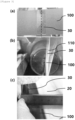
- FIG. 3 is an image showing an implemented example of a method for manufacturing a jelly-roll type electrode assembly according to an exemplary embodiment of the present disclosure.
- FIG. 3(a) shows the swelling tape attached on a slitting region included in the first electrode in a winding process (S50) after the swelling tape attaching step (S12).
- FIG. 3(b) the swelling tape attached such that one end portion matches the first end portion of the first electrode after the slitting step (S13).
- FIG. 3(c) of FIG. 3 shows an attached state of the swelling tape by disassembling the jelly-roll type electrode assembly after the winding process (S50).
- the method for manufacturing a jelly-roll type electrode assembly may further include a supply process (S20), an arrangement process (S30), a lamination process (S40), a winding process (S50), a taping process (S60), an inspection process (S70), and the like.
- the supply process (S20) may be a process of supplying the first electrode and the second electrode together with the first separator and the second separator after the first electrode preparation process (S10)
- the arrangement process (S30) may be a process of sequentially arranging the first electrode, the first separator, the second electrode, and the second separator supplied in the supply process (S20) and forming a stack.
- the lamination process (S40) may be a process of pressurizing and heat-fusing the stack manufactured in the arrangement process (S30), that is, the stack including the first electrode, the first separator, the second electrode, and the second separator, thereby providing an electrode assembly.
- the winding process (S50) may be a process of winding the electrode assembly on which the lamination process has been performed, and may further include a slitting process of cutting the electrode assembly to a set length before or after the winding process.
- the taping process (S60) may be a process of finishing an outer surface of the electrode assembly wound in the winding process (S50) with a seal tape, and the taping process may be performed to prevent defects such as the electrode assembly coming loose as a result of longitudinal end portions of the first electrode, the first separator, the second electrode, and the second separator being spaced apart.
- the inspection process (S70) may include a vision inspection step of determining defects by inspecting shapes, arrangements, damages, and the like of the first electrode, the first separator, the second electrode, and the second separator included in the electrode assembly, and a withstand voltage test step of determining defects by supplying power to the electrode assembly and measuring a withstand voltage.
- the swelling tape used in the method for manufacturing a jelly-roll type electrode assembly may be the same as the swelling tape described above with respect to the jelly-roll type electrode assembly.
- a width of the swelling tape may be 60% or greater and 100% or less based on 100% of a width of the first electrode.
- the widthof the swelling tape may be 70% or greater and 100% or less, 80% or greater and 100% or less, 60% or greater and 90% or less, 60% or greater and 80% or less, 60% or greater and 70% or less, or 70% or greater and 90% or less based on 100% of the width of the first electrode.
- a length, in a longitudinal direction, of the swelling tape may be 500% or greater and 7000% or less based on 100% of a thickness of the first electrode.
- the length of the swelling tape may be 600% or greater, 700% or greater, 800% or greater, or 1000% or greater based on 100% of the thickness of the first electrode, and the length of the swelling tape may be 6000% or less, 5000% or less, 4000% or less, or 3000% or less, preferably 2000% or less, 1700% or less, or 1400% or less based on 100% of the thickness of the first electrode.
- the length of the swelling tape slit after the step (c) may be within an appropriate range, that is, 250% or greater and 3500% or less, and preferably 250% or greater and 1000% or less based on 100% of the thickness of the first electrode
- the length, in the longitudinal direction, of the swelling tape after expansion may correspond to the thickness of the first electrode, and one end portion of the swelling tape effectively wraps around one longitudinal end portion of the first electrode, thereby more effectively minimizing the effect on electrochemical properties such as the capacity reduction rate of the battery including the swelling tape and preventing an internal short between the positive electrode and negative electrode even when the separator is damaged.
- the length, in the longitudinal direction, of the swelling tape may be 0.75 mm or longer and 10 mm or less.
- the length, in the longitudinal direction, of the swelling tape may be 1 mm or longer, 1.25 mm or longer, 1.5 mm or longer, 1.75 mm or longer, or 2 mm or longer
- the length, in the longitudinal direction, of the swelling tape may be 2.75 mm or less, 2.5 mm or less, 2.25 mm or less, or 2 mm or less.
- the first electrode may be a positive electrode
- the second electrode may be a negative electrode.
- a positive electrode and a negative electrode used in the method for manufacturing a jelly-roll type electrode assembly may be the same as those described above with respect to the jelly-roll type electrode assembly.
- An exemplary embodiment of the present disclosure provides a jelly-roll type electrode assembly manufactured by the above-described method for manufacturing a jelly-roll type electrode assembly.
- the jelly-roll type electrode assembly includes the swelling tape attached such that it expands and wraps around one longitudinal end portion of a positive electrode when impregnated with an electrolyte solution, thereby preventing a damage to the positive electrode and the separator from deformation of the electrode assembly due to contraction/expansion of the electrode during charging and discharging of the battery.
- the swelling tape can prevent an internal short between the positive electrode and the negative electrode to improve the stability and lifespan of the battery.
- the swelling tape wraps around the longitudinal end portion of the first electrode, the effects of relieving internal stress and improving roundness of the core portion may be improved due to porous material characteristics of the swelling tape.
- An exemplary embodiment of the present disclosure provides a secondary battery including the jelly-roll type electrode assembly described above, and a battery case for accommodating the electrode assembly.
- the secondary battery may include the electrode assembly according to an exemplary embodiment described above and a battery case for accommodating the electrode assembly.
- the secondary battery according to the present disclosure can prevent an internal short between the positive electrode and the negative electrode even when the electrode assembly is deformed due to contraction/expansion of the electrode during charging and discharging of the battery, thereby improving the stability and lifespan of the battery.
- the battery case may have a cylindrical shape.
- the battery case may have a cylindrical shape, a square shape, a pouch shaped or the like depending on uses, but is not limited thereto.
- the battery case may include an electrolyte therein.
- the electrolyte may include an organic liquid electrolyte, an inorganic liquid electrolyte, a solid polymer electrolyte, a gel-type polymer electrolyte, a solid inorganic electrolyte, or a molten-type inorganic electrolyte that may be used in the manufacturing of the lithium secondary battery, but is not limited thereto.
- the electrolyte may include a non-aqueous organic solvent and a metal salt.
- an aprotic organic solvent such as N-methyl-2-pyrrolidinone, propylene carbonate, ethylene carbonate, butylene carbonate, dimethyl carbonate, diethyl carbonate, ethyl methyl carbonate, gamma-butyllolactone, 1,2-dimetoxy ethane, tetrahydrofuran, 2-methyltetrahydrofuran, dimethylsulfoxide, 1,3-dioxolane, formamide, dimethylformamide, dioxolane, acetonitrile, nitromethane, methyl formate, methyl acetate, phosphoric acid triester, trimethoxy methane, dioxolane derivative, sulfolane, methyl sulfolane, 1,3-dimethyl-2-imidazolidinone, propylene carbonate derivative, tetrahydrofuran derivative, ether,
- an aprotic organic solvent such as N-methyl-2-pyrrolidinone, propy
- a lithium salt may be used as the metal salt, and the lithium salt is a material that is readily soluble in the non-aqueous electrolyte solution, in which, for example, one or more species selected from the group consisting of F-, Cl-, I-, NO 3 - , N(CN) 2 - , BF 4 - , ClO 4 - , PF 6 - , (CF 3 ) 2 PF 4 - , (CF 3 ) 3 PF 3 - , (CF 3 ) 4 PF 2 - , (CF 3 ) 5 PF - , (CF 3 ) 6 P - , CF 3 SO 3 - , CF 3 CF 2 SO 3 - , (CF 3 SO 2 ) 2 N - , (FSO 2 ) 2 N - , CF 3 CF 2 (CF 3 ) 2 CO - , (CF 3 SO 2 ) 2 CH - , (SF 5 ) 3
- one or more additives for example, a haloalkylene carbonate-based compound such as difluoroethylene carbonate, pyridine, triethylphosphite, triethanolamine, cyclic ether, ethylenediamine, n-glyme, hexaphosphoric triamide, a nitrobenzene derivative, sulfur, a quinone imine dye, N-substituted oxazolidinone, N,N-substituted imidazolidine, ethylene glycol dialkyl ether, an ammonium salt, pyrrole, 2-methoxy ethanol, or aluminum trichloride, may be further included in the electrolyte for the purpose of improving the lifetime characteristic of the battery, suppressing a decrease in battery capacity, improving discharge capacity of the battery, and the like, in addition to the above-described electrolyte components.
- a haloalkylene carbonate-based compound such as difluoroethylene carbonate, pyridine, triethyl
- a positive electrode having a total thickness of 154 um was prepared by preparing an Al foil having a thickness of 15 um and a length of 63.9 mm in the width direction as a positive electrode current collector, and applying and drying a positive electrode active material slurry including an NMCA (Ni-Mn-Co-Al) composite having a Ni content of 92% or more as a positive electrode active material and CNTs as a conductive material on the positive electrode current collector to form a positive electrode active material layer.
- NMCA Ni-Mn-Co-Al
- a swelling tape with a thickness of 52 um having an adhesive layer including a copolymer of ethyl acrylate (EA) and polyethyl methacrylate (PEMA) on one surface of a base layer made of polyurethane (PU) was prepared, and was attached on one surface of a slitting region of the positive electrode to have a length of 62 mm in the width direction and a length of 10 mm in the longitudinal direction.
- EA ethyl acrylate
- PEMA polyethyl methacrylate
- a negative electrode having a total thickness of 187 um was prepared by preparing a Cu foil having a thickness of 10 um and a length of 62 mm in the width direction as a negative electrode current collector, and applying and drying a negative electrode active material slurry including artificial graphite and natural graphite as a negative electrode active material in an amount of 50 parts by weight, respectively, on the negative electrode current collector to form a negative electrode active material layer.
- the positive electrode, the first separator, the negative electrode, and the second separator were sequentially arranged to form a stack, which was then pressurized and heat-fused.
- a central portion of the slitting region was slit, the stack was wound such that a first end portion the positive electrode from which winding begins was located in the core portion, and a seal tape made of PET was attached to a second end portion at which the winding ends to wrap around upper and lower outer peripheral surfaces of the jelly-roll and finished, resulting in a jelly-roll type electrode assembly.
- the seal tape with a length of 62 mm in the longitudinal direction, a length of 10 mm in the width direction, and a thickness of 22 um was used, and a length of the swelling tape after slitting was 5 mm.
- a secondary battery was prepared by inserting the jelly-roll type electrode assembly into a cylindrical battery case, injecting an electrolyte solution in which ethylene carbonate (EC), dimethyl carbonate (DMC), and ethyl methyl carbonate (EMC) were mixed at a weight ratio of 4:9:3 and LiPF 6 was dissolved to be 15 wt%, and sealing the cylindrical battery case with a cap assembly.
- EC ethylene carbonate
- DMC dimethyl carbonate
- EMC ethyl methyl carbonate
- a jelly-roll type electrode assembly and a secondary battery were prepared in the same manner as in Example 1, except that the swelling tape was attached on each of both surfaces of the slitting region of the positive electrode to have a length of 62 mm in the width direction and a length of 5 mm in the longitudinal direction.
- a jelly-roll type electrode assembly and a secondary battery were prepared in the same manner as Example 1, except that a PET tape was attached on one surface of the slitting region of the positive electrode to have a length of 62 mm in the width direction and a length of 10 mm in the longitudinal direction.
- a jelly-roll type electrode assembly and a secondary battery were prepared in the same manner as in Example 1, except that the swelling tape was not attached in the slitting region of the positive electrode.
- a jelly-roll type electrode assembly and a secondary battery were prepared in the same manner as in Example 1, except that the central portion of the slitting region was slit without attaching the swelling tape in the slitting region of the positive electrode, the slit positive electrode was spaced, a PET tape was attached on each of both surfaces of the slitting region to have a length of 62 mm in the width direction and a length of 10 mm in the longitudinal direction, and then the central portion was additionally slit, resulting in the structure of (b) of FIG. 1 .
- a sample (a length of 10 mm in the longitudinal direction and a length of 62 mm in the width direction) made of the same material as the swelling tape used in Example 1 and Example 2 was prepared, and an electrolyte solution in which LiPF 6 as an electrolyte was dissolved in a mixed solvent of ethylene carbonate (EC), dimethyl carbonate (DMC), and ethyl methyl carbonate (EMC) was prepared. Thereafter, the swelling tape sample was impregnated with the electrolyte solution for 60 minutes, and a length of the swelling tape before expansion and a length of the swelling tape after expansion were measured, respectively.
- the composition of the electrolyte solution used for swelling evaluation is shown in Table 1 below.
- FIG. 4 shows calculated ratios of the lengths, in the width direction (transverse direction; TD) and the longitudinal direction (machine direction; MD), of the swelling tape after expansion with respect to the length of the swelling tape before expansion after impregnating the swelling tape sample in the DMC and the electrolyte solution having the composition of Experimental Example 1-1 for 60 minutes, respectively.
- the lengths and widths of the swelling tape after expansion were about 140% of the length of the swelling tape before expansion.
- the length expansion of the swelling tape occurred at the same ratio in both the length and width directions and that the swelling tape expanded by about 120% on one side from the central portion to one end portion of the swelling tape before expansion.
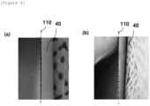
- Example 1 and Comparative Example 1 were activated by performing 2 cycles of 4.2 V-2.5 V, 0.2 C charging, and 0.2 C discharging, respectively, and then disassembled to prepare jelly-roll type electrode assemblies before and after activation. Then, the end portion of the positive electrode of each of the jelly-roll type electrode assemblies was observed with naked eyes, and the evaluation results are shown in FIGS. 5 and 6 below.
- FIG. 5(a) shows the first end portion of the first electrode of the jelly-roll type electrode assembly before activation according to Example 1
- FIG. 5(b) shows the first end portion of the first electrode of the jelly-roll type electrode assembly after activation according to Example 1
- FIG. 6(a) shows the first end portion of the first electrode of the jelly-roll type electrode assembly before activation according to Comparative Example 1
- FIG. 6(b) shows the first end portion of the first electrode of the jelly-roll type electrode assembly after activation according to Comparative Example 1
- the swelling tape attached such that one end portion matched the first end portion of the first electrode before activation was expanded after activation to wrap around the first end portion of the first electrode.
- the length (2L) of the swelling tape attached on at least one surface of the slitting region included in the first electrode was 10 mm
- the length (L) of the swelling tape before expansion was 5 mm
- the length (L') of the swelling tape after expansion was 7 mm
- the expanded length (L s ) of the swelling tape was a total of 2 mm.
- the length (L') of the swelling tape after expansion expanded by about 140% of the length (L) of the swelling tape before expansion and expanded by 1 mm on one side from the central portion to one end portion of the swelling tape before expansion, i.e., by 120% of the length (L) of the swelling tape before expansion.
- the jelly-roll type electrode assembly including the swelling tape according to the present disclosure is expanded by the electrolyte solution, and after expansion, the swelling tape effectively wraps around the first end portion of the first electrode.
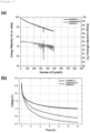
- Example 1 The secondary batteries prepared in Example 1 and Comparative Example 2 were tested for battery characteristics in a 25°C cycle test.
- the coulombic efficiency was analyzed in order to check a short behavior during the cycle
- the room temperature-voltage tracking was performed in order to evaluate an abnormal behavior in more detail, and the evaluation results are shown in FIG. 7 .
- FIG. 7(a) shows the change in coulombic efficiency with respect to cycle progress for the secondary batteries prepared in Example 1 and Comparative Example 2
- FIG. 7(b) shows the room temperature-voltage tracking evaluation result over time for the secondary batteries prepared in Example 1 and Comparative Example 2.
- FIG. 7(a) it was confirmed that the secondary battery according to Example 1 did not exhibit any special abnormal behavior, but the secondary battery according to Comparative Example 2 exhibited an abnormal coulombic efficiency behavior, that is, an occurrence of leak current.
- FIG. 7(b) it was confirmed that the secondary battery according to Example 1 maintained a voltage of 1.0 V or higher even after 12 hours, but the secondary battery according to Comparative Example 2 failed to maintain a constant voltage and gradually decreased in voltage over time. With this, it can be seen that the separator was damaged and an internal short occurred.
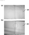
- Example 1 Thereafter, the secondary battery according to Example 1 was disassembled and visually evaluated for the presence or absence of damage to the separator, and the results are shown in FIG. 8 .
- FIG. 8(a) is an image showing a state of a portion of the separator facing the first electrode included in the secondary battery prepared in Example 1
- FIG. 8(b) is an image showing a state of a portion of the separator facing the first electrode included in the secondary battery prepared in Comparative Example 2.
- the secondary battery according to the present disclosure can prevent an internal short between the positive electrode and the negative electrode even when the electrode assembly is deformed due to contraction/expansion of the electrode during charging and discharging of the battery, thereby improving the stability and lifespan of the battery.
- the roundness was evaluated after 20 cycles at 25°C, and results thereof are shown in Table 2 and FIG. 9 .
- the roundness (circularity) (%) indicates a degree to which a shape of an electrode assembly is closer to a circle.
- the maximum and minimum separation distances between the winding axis and the positive electrode were measured from the computed tomography (CT) image of the positive electrode, and the ratio (%) of the minimum separation distance between the winding axis and the positive electrode with respect to 100% of the maximum separation distance between the winding axis and the positive electrode was calculated.
- CT computed tomography
- FIG. 9 is an image showing results of roundness evaluation for secondary batteries prepared in Example 1 and Comparative Example 3.
- Table 2 in the case of the secondary battery according to Comparative Example 3 where the longitudinal end portion of the positive electrode was wrapped around using the PET protective tape, and after expansion, a structure similar to that of the secondary battery according to Example 1 including a swelling tape was provided, it was confirmed that the takt time was 3.0s, i.e., increased approximately twice, as compared with the secondary battery according to Example 1, and the productivity was lower.
- the method for manufacturing a jelly-roll type electrode assembly includes the step of attaching a swelling tape, and thus enables the jelly-roll type electrode assembly, which includes the swelling tape attached in order to wrap around one longitudinal end portion of the positive electrode while minimizing separate additional processes, to be provided and produced in a continuous process manner using an existing roll-to-roll process facility, making it possible to improve productivity and cost savings.
- the secondary battery according to the present disclosure includes a structure where the swelling tape wraps around the longitudinal end portion of the first electrode after expansion, so that even when the electrode assembly is deformed due to contraction/expansion of the electrode during charging and discharging of the battery, the internal short between the positive electrode and the negative electrode can be prevented to improve the stability and lifespan of the battery, and the effects of relieving internal stress and improving roundness of the core portion are excellent due to porous material characteristics of the swelling tape.
Landscapes
- Chemical & Material Sciences (AREA)
- Chemical Kinetics & Catalysis (AREA)
- Electrochemistry (AREA)
- General Chemical & Material Sciences (AREA)
- Engineering & Computer Science (AREA)
- Manufacturing & Machinery (AREA)
- Physics & Mathematics (AREA)
- Condensed Matter Physics & Semiconductors (AREA)
- General Physics & Mathematics (AREA)
- Inorganic Chemistry (AREA)
- Secondary Cells (AREA)
- Materials Engineering (AREA)
- Connection Of Batteries Or Terminals (AREA)
Applications Claiming Priority (3)
| Application Number | Priority Date | Filing Date | Title |
|---|---|---|---|
| KR20220121663 | 2022-09-26 | ||
| KR1020230127959A KR102917779B1 (ko) | 2022-09-26 | 2023-09-25 | 젤리-롤형 전극조립체, 젤리-롤형 전극조립체 제조방법 및 이를 포함하는 이차전지 |
| PCT/KR2023/014720 WO2024071934A1 (ko) | 2022-09-26 | 2023-09-26 | 젤리-롤형 전극조립체, 젤리-롤형 전극조립체 제조방법 및 이를 포함하는 이차전지 |
Publications (2)
| Publication Number | Publication Date |
|---|---|
| EP4407739A1 true EP4407739A1 (de) | 2024-07-31 |
| EP4407739A4 EP4407739A4 (de) | 2025-07-23 |
Family
ID=90478716
Family Applications (1)
| Application Number | Title | Priority Date | Filing Date |
|---|---|---|---|
| EP23873049.3A Pending EP4407739A4 (de) | 2022-09-26 | 2023-09-26 | Jelly-roll-elektrodenanordnung, herstellungsverfahren für jelly-roll-elektrodenanordnung und sekundärbatterie damit |
Country Status (4)
| Country | Link |
|---|---|
| US (1) | US20250023214A1 (de) |
| EP (1) | EP4407739A4 (de) |
| JP (1) | JP7838882B2 (de) |
| WO (1) | WO2024071934A1 (de) |
Families Citing this family (2)
| Publication number | Priority date | Publication date | Assignee | Title |
|---|---|---|---|---|
| WO2026070988A1 (ja) * | 2024-09-30 | 2026-04-02 | パナソニックIpマネジメント株式会社 | 二次電池及び二次電池用正極 |
| WO2026070869A1 (ja) * | 2024-09-30 | 2026-04-02 | パナソニックIpマネジメント株式会社 | 二次電池及び二次電池用正極 |
Family Cites Families (16)
| Publication number | Priority date | Publication date | Assignee | Title |
|---|---|---|---|---|
| KR101587312B1 (ko) * | 2012-11-16 | 2016-01-21 | 주식회사 엘지화학 | 간극 충진용 스웰링 테이프 |
| KR101851429B1 (ko) * | 2015-02-13 | 2018-04-23 | 주식회사 엘지화학 | 이차전지 |
| JP6558440B2 (ja) * | 2015-09-09 | 2019-08-14 | 株式会社村田製作所 | 二次電池 |
| JP6885047B2 (ja) * | 2016-01-19 | 2021-06-09 | 株式会社Gsユアサ | 蓄電素子、及び、蓄電素子の製造方法 |
| CN205376656U (zh) * | 2016-01-20 | 2016-07-06 | 宁德新能源科技有限公司 | 二次电池 |
| US20200044276A1 (en) * | 2017-01-31 | 2020-02-06 | Panasonic Intellectual Property Management Co., Ltd. | Secondary battery |
| KR102443061B1 (ko) * | 2017-03-15 | 2022-09-14 | 삼성전자주식회사 | 온도 변화에 따른 가변층을 포함하는 재충전가능한 배터리 |
| KR102422921B1 (ko) * | 2017-04-07 | 2022-07-20 | 주식회사 엘지에너지솔루션 | 경화 방지 테이프가 부착되어 있는 젤리-롤형 전극조립체를 포함하는 원통형 전지셀 |
| JP7342446B2 (ja) * | 2019-06-19 | 2023-09-12 | トヨタ自動車株式会社 | 蓄電素子 |
| WO2021106763A1 (ja) * | 2019-11-28 | 2021-06-03 | 株式会社村田製作所 | 二次電池、電子機器及び電動工具 |
| KR20220000662A (ko) * | 2020-06-26 | 2022-01-04 | 주식회사 엘지에너지솔루션 | 이차 전지 및 이를 포함하는 디바이스 |
| KR20220061552A (ko) * | 2020-11-06 | 2022-05-13 | 주식회사 엘지에너지솔루션 | 이차전지 및 이를 포함하는 디바이스 |
| KR102711383B1 (ko) * | 2020-11-19 | 2024-09-30 | 삼성에스디아이 주식회사 | 이차 전지 |
| KR102624206B1 (ko) | 2021-02-25 | 2024-01-15 | 인하대학교 산학협력단 | ArF 위상반전 블랭크 마스크용 차광막 제조 방법 및 장치 |
| JP7285873B2 (ja) * | 2021-03-03 | 2023-06-02 | プライムプラネットエナジー&ソリューションズ株式会社 | 二次電池 |
| JP2025511662A (ja) * | 2022-12-01 | 2025-04-16 | エルジー エナジー ソリューション リミテッド | 電極組立体およびそれを含む二次電池 |
-
2023
- 2023-09-26 US US18/713,949 patent/US20250023214A1/en active Pending
- 2023-09-26 WO PCT/KR2023/014720 patent/WO2024071934A1/ko not_active Ceased
- 2023-09-26 EP EP23873049.3A patent/EP4407739A4/de active Pending
- 2023-09-26 JP JP2024524730A patent/JP7838882B2/ja active Active
Also Published As
| Publication number | Publication date |
|---|---|
| JP7838882B2 (ja) | 2026-04-01 |
| WO2024071934A1 (ko) | 2024-04-04 |
| JP2024541925A (ja) | 2024-11-13 |
| US20250023214A1 (en) | 2025-01-16 |
| EP4407739A4 (de) | 2025-07-23 |
Similar Documents
| Publication | Publication Date | Title |
|---|---|---|
| EP4407739A1 (de) | Jelly-roll-elektrodenanordnung, herstellungsverfahren für jelly-roll-elektrodenanordnung und sekundärbatterie damit | |
| KR20110063655A (ko) | 각형 비수 전해질 이차전지 및 그 제조방법 | |
| EP3644426A1 (de) | Verfahren zur herstellung einer flexiblen batterie und dadurch hergestellte flexible batterie | |
| KR102917779B1 (ko) | 젤리-롤형 전극조립체, 젤리-롤형 전극조립체 제조방법 및 이를 포함하는 이차전지 | |
| EP4611084A1 (de) | Elektrodenanordnung und sekundärbatterie damit | |
| EP4611107A1 (de) | Elektrodenanordnung und sekundärbatterie damit | |
| CN118235279A (zh) | 卷绕型电极组件、用于卷绕型电极组件的制造方法以及包括该卷绕型电极组件的二次电池 | |
| EP4625595A1 (de) | Jelly-roll-elektrodenanordnung, herstellungsverfahren dafür und sekundärbatterie damit | |
| EP4629394A1 (de) | Jelly-roll-elektrodenanordnung, verfahren zur herstellung einer jelly-roll-elektrodenanordnung und sekundärbatterie damit | |
| EP4579865A1 (de) | Jelly-roll-elektrodenanordnung, herstellungsverfahren für jelly-roll-elektrodenanordnung und sekundärbatterie damit | |
| KR102937578B1 (ko) | 젤리-롤형 전극조립체 및 이를 포함하는 이차전지 | |
| EP4369467A1 (de) | Jelly-roll-elektrodenanordnung und sekundärbatterie damit | |
| EP4401188A1 (de) | Jelly-roll-elektrodenanordnung und sekundärbatterie damit | |
| EP4471930A1 (de) | Jelly-roll-elektrodenanordnung und sekundärbatterie damit | |
| KR20250008494A (ko) | 전극조립체 및 이를 포함하는 이차전지 | |
| EP4407738A1 (de) | Jelly-roll-elektrodenanordnung und sekundärbatterie damit | |
| KR20240068277A (ko) | 젤리-롤형 전극조립체 및 이를 포함하는 이차전지 | |
| EP4428984A1 (de) | Jelly-roll-elektrodenanordnung, verfahren zur herstellung einer jelly-roll-elektrodenanordnung und sekundärbatterie damit | |
| KR20250008156A (ko) | 젤리-롤형 전극조립체, 젤리-롤형 전극조립체 제조방법 및 이를 포함하는 이차전지 | |
| KR20250040196A (ko) | 젤리-롤형 전극조립체 및 이를 포함하는 이차전지 | |
| KR20250040194A (ko) | 젤리-롤형 전극조립체 및 이를 포함하는 이차전지 | |
| KR20240097601A (ko) | 리폼 핀, 리폼 장치, 이를 이용한 젤리-롤형 전극조립체 제조방법 및 젤리-롤형 전극조립체 | |
| KR20240082171A (ko) | 젤리-롤형 전극조립체 및 이를 포함하는 이차전지 | |
| KR20250066035A (ko) | 젤리-롤형 전극조립체 및 이를 포함하는 이차전지 | |
| KR20240166675A (ko) | 이차전지, 이를 포함하는 전지시스템 및 배터리팩 |
Legal Events
| Date | Code | Title | Description |
|---|---|---|---|
| STAA | Information on the status of an ep patent application or granted ep patent |
Free format text: STATUS: THE INTERNATIONAL PUBLICATION HAS BEEN MADE |
|
| PUAI | Public reference made under article 153(3) epc to a published international application that has entered the european phase |
Free format text: ORIGINAL CODE: 0009012 |
|
| STAA | Information on the status of an ep patent application or granted ep patent |
Free format text: STATUS: REQUEST FOR EXAMINATION WAS MADE |
|
| 17P | Request for examination filed |
Effective date: 20240423 |
|
| AK | Designated contracting states |
Kind code of ref document: A1 Designated state(s): AL AT BE BG CH CY CZ DE DK EE ES FI FR GB GR HR HU IE IS IT LI LT LU LV MC ME MK MT NL NO PL PT RO RS SE SI SK SM TR |
|
| A4 | Supplementary search report drawn up and despatched |
Effective date: 20250623 |
|
| RIC1 | Information provided on ipc code assigned before grant |
Ipc: H01M 10/0587 20100101AFI20250616BHEP Ipc: C09J 7/38 20180101ALI20250616BHEP Ipc: C09J 7/25 20180101ALI20250616BHEP Ipc: H01M 10/0569 20100101ALI20250616BHEP Ipc: C09J 5/00 20060101ALI20250616BHEP Ipc: H01M 10/0525 20100101ALI20250616BHEP Ipc: H01M 50/107 20210101ALI20250616BHEP Ipc: H01M 50/474 20210101ALI20250616BHEP Ipc: H01M 10/04 20060101ALI20250616BHEP Ipc: H01M 50/477 20210101ALI20250616BHEP Ipc: H01M 50/486 20210101ALI20250616BHEP Ipc: H01M 50/489 20210101ALI20250616BHEP Ipc: H01M 50/595 20210101ALI20250616BHEP |
|
| DAV | Request for validation of the european patent (deleted) | ||
| DAX | Request for extension of the european patent (deleted) |