EP4407729A2 - Batteriesystem - Google Patents
Batteriesystem Download PDFInfo
- Publication number
- EP4407729A2 EP4407729A2 EP23215064.9A EP23215064A EP4407729A2 EP 4407729 A2 EP4407729 A2 EP 4407729A2 EP 23215064 A EP23215064 A EP 23215064A EP 4407729 A2 EP4407729 A2 EP 4407729A2
- Authority
- EP
- European Patent Office
- Prior art keywords
- intermediate plate
- unit
- unit cell
- hydrogen sulfide
- battery
- Prior art date
- Legal status (The legal status is an assumption and is not a legal conclusion. Google has not performed a legal analysis and makes no representation as to the accuracy of the status listed.)
- Pending
Links
Images


Classifications
-
- H—ELECTRICITY
- H01—ELECTRIC ELEMENTS
- H01M—PROCESSES OR MEANS, e.g. BATTERIES, FOR THE DIRECT CONVERSION OF CHEMICAL ENERGY INTO ELECTRICAL ENERGY
- H01M10/00—Secondary cells; Manufacture thereof
- H01M10/42—Methods or arrangements for servicing or maintenance of secondary cells or secondary half-cells
- H01M10/4228—Leak testing of cells or batteries
-
- H—ELECTRICITY
- H01—ELECTRIC ELEMENTS
- H01M—PROCESSES OR MEANS, e.g. BATTERIES, FOR THE DIRECT CONVERSION OF CHEMICAL ENERGY INTO ELECTRICAL ENERGY
- H01M10/00—Secondary cells; Manufacture thereof
- H01M10/42—Methods or arrangements for servicing or maintenance of secondary cells or secondary half-cells
- H01M10/48—Accumulators combined with arrangements for measuring, testing or indicating the condition of cells, e.g. the level or density of the electrolyte
- H01M10/482—Accumulators combined with arrangements for measuring, testing or indicating the condition of cells, e.g. the level or density of the electrolyte for several batteries or cells simultaneously or sequentially
-
- G—PHYSICS
- G01—MEASURING; TESTING
- G01L—MEASURING FORCE, STRESS, TORQUE, WORK, MECHANICAL POWER, MECHANICAL EFFICIENCY, OR FLUID PRESSURE
- G01L5/00—Apparatus for, or methods of, measuring force, work, mechanical power, or torque, specially adapted for specific purposes
- G01L5/16—Apparatus for, or methods of, measuring force, work, mechanical power, or torque, specially adapted for specific purposes for measuring several components of force
- G01L5/161—Apparatus for, or methods of, measuring force, work, mechanical power, or torque, specially adapted for specific purposes for measuring several components of force using variations in ohmic resistance
- G01L5/1627—Apparatus for, or methods of, measuring force, work, mechanical power, or torque, specially adapted for specific purposes for measuring several components of force using variations in ohmic resistance of strain gauges
-
- H—ELECTRICITY
- H01—ELECTRIC ELEMENTS
- H01M—PROCESSES OR MEANS, e.g. BATTERIES, FOR THE DIRECT CONVERSION OF CHEMICAL ENERGY INTO ELECTRICAL ENERGY
- H01M10/00—Secondary cells; Manufacture thereof
- H01M10/04—Construction or manufacture in general
- H01M10/0468—Compression means for stacks of electrodes and separators
-
- H—ELECTRICITY
- H01—ELECTRIC ELEMENTS
- H01M—PROCESSES OR MEANS, e.g. BATTERIES, FOR THE DIRECT CONVERSION OF CHEMICAL ENERGY INTO ELECTRICAL ENERGY
- H01M10/00—Secondary cells; Manufacture thereof
- H01M10/04—Construction or manufacture in general
- H01M10/0481—Compression means other than compression means for stacks of electrodes and separators
-
- H—ELECTRICITY
- H01—ELECTRIC ELEMENTS
- H01M—PROCESSES OR MEANS, e.g. BATTERIES, FOR THE DIRECT CONVERSION OF CHEMICAL ENERGY INTO ELECTRICAL ENERGY
- H01M10/00—Secondary cells; Manufacture thereof
- H01M10/05—Accumulators with non-aqueous electrolyte
- H01M10/052—Li-accumulators
-
- H—ELECTRICITY
- H01—ELECTRIC ELEMENTS
- H01M—PROCESSES OR MEANS, e.g. BATTERIES, FOR THE DIRECT CONVERSION OF CHEMICAL ENERGY INTO ELECTRICAL ENERGY
- H01M10/00—Secondary cells; Manufacture thereof
- H01M10/05—Accumulators with non-aqueous electrolyte
- H01M10/052—Li-accumulators
- H01M10/0525—Rocking-chair batteries, i.e. batteries with lithium insertion or intercalation in both electrodes; Lithium-ion batteries
-
- H—ELECTRICITY
- H01—ELECTRIC ELEMENTS
- H01M—PROCESSES OR MEANS, e.g. BATTERIES, FOR THE DIRECT CONVERSION OF CHEMICAL ENERGY INTO ELECTRICAL ENERGY
- H01M10/00—Secondary cells; Manufacture thereof
- H01M10/05—Accumulators with non-aqueous electrolyte
- H01M10/056—Accumulators with non-aqueous electrolyte characterised by the materials used as electrolytes, e.g. mixed inorganic/organic electrolytes
- H01M10/0561—Accumulators with non-aqueous electrolyte characterised by the materials used as electrolytes, e.g. mixed inorganic/organic electrolytes the electrolyte being constituted of inorganic materials only
- H01M10/0562—Solid materials
-
- H—ELECTRICITY
- H01—ELECTRIC ELEMENTS
- H01M—PROCESSES OR MEANS, e.g. BATTERIES, FOR THE DIRECT CONVERSION OF CHEMICAL ENERGY INTO ELECTRICAL ENERGY
- H01M10/00—Secondary cells; Manufacture thereof
- H01M10/42—Methods or arrangements for servicing or maintenance of secondary cells or secondary half-cells
- H01M10/4207—Methods or arrangements for servicing or maintenance of secondary cells or secondary half-cells for several batteries or cells simultaneously or sequentially
-
- H—ELECTRICITY
- H01—ELECTRIC ELEMENTS
- H01M—PROCESSES OR MEANS, e.g. BATTERIES, FOR THE DIRECT CONVERSION OF CHEMICAL ENERGY INTO ELECTRICAL ENERGY
- H01M10/00—Secondary cells; Manufacture thereof
- H01M10/42—Methods or arrangements for servicing or maintenance of secondary cells or secondary half-cells
- H01M10/48—Accumulators combined with arrangements for measuring, testing or indicating the condition of cells, e.g. the level or density of the electrolyte
-
- H—ELECTRICITY
- H01—ELECTRIC ELEMENTS
- H01M—PROCESSES OR MEANS, e.g. BATTERIES, FOR THE DIRECT CONVERSION OF CHEMICAL ENERGY INTO ELECTRICAL ENERGY
- H01M50/00—Constructional details or processes of manufacture of the non-active parts of electrochemical cells other than fuel cells, e.g. hybrid cells
- H01M50/10—Primary casings; Jackets or wrappings
- H01M50/102—Primary casings; Jackets or wrappings characterised by their shape or physical structure
- H01M50/105—Pouches or flexible bags
-
- H—ELECTRICITY
- H01—ELECTRIC ELEMENTS
- H01M—PROCESSES OR MEANS, e.g. BATTERIES, FOR THE DIRECT CONVERSION OF CHEMICAL ENERGY INTO ELECTRICAL ENERGY
- H01M50/00—Constructional details or processes of manufacture of the non-active parts of electrochemical cells other than fuel cells, e.g. hybrid cells
- H01M50/20—Mountings; Secondary casings or frames; Racks, modules or packs; Suspension devices; Shock absorbers; Transport or carrying devices; Holders
- H01M50/204—Racks, modules or packs for multiple batteries or multiple cells
- H01M50/207—Racks, modules or packs for multiple batteries or multiple cells characterised by their shape
- H01M50/209—Racks, modules or packs for multiple batteries or multiple cells characterised by their shape adapted for prismatic or rectangular cells
-
- H—ELECTRICITY
- H01—ELECTRIC ELEMENTS
- H01M—PROCESSES OR MEANS, e.g. BATTERIES, FOR THE DIRECT CONVERSION OF CHEMICAL ENERGY INTO ELECTRICAL ENERGY
- H01M50/00—Constructional details or processes of manufacture of the non-active parts of electrochemical cells other than fuel cells, e.g. hybrid cells
- H01M50/20—Mountings; Secondary casings or frames; Racks, modules or packs; Suspension devices; Shock absorbers; Transport or carrying devices; Holders
- H01M50/204—Racks, modules or packs for multiple batteries or multiple cells
- H01M50/207—Racks, modules or packs for multiple batteries or multiple cells characterised by their shape
- H01M50/211—Racks, modules or packs for multiple batteries or multiple cells characterised by their shape adapted for pouch cells
-
- H—ELECTRICITY
- H01—ELECTRIC ELEMENTS
- H01M—PROCESSES OR MEANS, e.g. BATTERIES, FOR THE DIRECT CONVERSION OF CHEMICAL ENERGY INTO ELECTRICAL ENERGY
- H01M50/00—Constructional details or processes of manufacture of the non-active parts of electrochemical cells other than fuel cells, e.g. hybrid cells
- H01M50/20—Mountings; Secondary casings or frames; Racks, modules or packs; Suspension devices; Shock absorbers; Transport or carrying devices; Holders
- H01M50/262—Mountings; Secondary casings or frames; Racks, modules or packs; Suspension devices; Shock absorbers; Transport or carrying devices; Holders with fastening means, e.g. locks
- H01M50/264—Mountings; Secondary casings or frames; Racks, modules or packs; Suspension devices; Shock absorbers; Transport or carrying devices; Holders with fastening means, e.g. locks for cells or batteries, e.g. straps, tie rods or peripheral frames
-
- H—ELECTRICITY
- H01—ELECTRIC ELEMENTS
- H01M—PROCESSES OR MEANS, e.g. BATTERIES, FOR THE DIRECT CONVERSION OF CHEMICAL ENERGY INTO ELECTRICAL ENERGY
- H01M2220/00—Batteries for particular applications
- H01M2220/20—Batteries in motive systems, e.g. vehicle, ship, plane
-
- H—ELECTRICITY
- H01—ELECTRIC ELEMENTS
- H01M—PROCESSES OR MEANS, e.g. BATTERIES, FOR THE DIRECT CONVERSION OF CHEMICAL ENERGY INTO ELECTRICAL ENERGY
- H01M2300/00—Electrolytes
- H01M2300/0017—Non-aqueous electrolytes
- H01M2300/0065—Solid electrolytes
- H01M2300/0068—Solid electrolytes inorganic
-
- Y—GENERAL TAGGING OF NEW TECHNOLOGICAL DEVELOPMENTS; GENERAL TAGGING OF CROSS-SECTIONAL TECHNOLOGIES SPANNING OVER SEVERAL SECTIONS OF THE IPC; TECHNICAL SUBJECTS COVERED BY FORMER USPC CROSS-REFERENCE ART COLLECTIONS [XRACs] AND DIGESTS
- Y02—TECHNOLOGIES OR APPLICATIONS FOR MITIGATION OR ADAPTATION AGAINST CLIMATE CHANGE
- Y02E—REDUCTION OF GREENHOUSE GAS [GHG] EMISSIONS, RELATED TO ENERGY GENERATION, TRANSMISSION OR DISTRIBUTION
- Y02E60/00—Enabling technologies; Technologies with a potential or indirect contribution to GHG emissions mitigation
- Y02E60/10—Energy storage using batteries
Definitions
- the present disclosure relates to battery systems.
- JP 2022-46077 A discloses a battery system that cools a secondary battery with a cooler when generation of hydrogen sulfide is predicted or detected in the secondary battery using a sulfur-based material for at least one of the positive electrode and the solid electrolyte.
- JP 2022-46077 A by detecting pressure in a battery case containing the secondary battery or hydrogen sulfide concentration (sulfur concentration) in the battery case, hydrogen sulfide gas that has been generated from the secondary battery is detected.
- JP 2022-46077 A generation of hydrogen sulfide gas cannot be detected, until the hydrogen sulfide gas generated from the secondary battery fills the battery case, and pressure in the battery case rises, or until hydrogen sulfide concentration in the battery case increases.
- the present disclosure makes it possible to detect the generation of hydrogen sulfide before the hydrogen sulfide gas fills the battery case.
- the battery system of the present disclosure includes a unit cell that is a sulfide-based all-solid-state battery, a battery module in which a plurality of the unit cells is stacked between a pair of restraining members, an intermediate plate disposed between the stacked unit cells, a detection unit configured to detect a load applied to the intermediate plate, and an estimation unit configured to estimate generation of hydrogen sulfide in the unit cell based on a change in the load applied to the intermediate plate.
- the unit cell is constituted of a sulfide-based all-solid-state battery.
- the sulfide-based all-solid-state battery contains a sulfur component in at least one of the positive electrode material and the solid electrolyte material.
- the unit cells constitute the battery module by being stacked between the pair of restraining members.
- the intermediate plate is disposed between the stacked unit cells.
- the detection unit detects the load applied to the intermediate plate. When the hydrogen sulfide gas is generated inside the unit cell, internal pressure of the unit cell increases, and a volume of the unit cell increases. As the volume of the unit cell increases, the load applied to the intermediate plate changes.
- the estimation unit estimates the generation of hydrogen sulfide in the unit cell based on the change in the load applied to the intermediate plate. Since the estimation unit estimates the generation of hydrogen sulfide in the unit cell based on the change in the load applied to the intermediate plate, the battery system will be able to detect the generation of hydrogen sulfide before the battery case is filled with hydrogen sulfide gas.
- the intermediate plate may be fixed to a base member in a cantilevered state.
- the restraining members are fixed to the base member.
- the detection unit may be a strain gauge provided on the intermediate plate.
- the intermediate plate is fixed to the base member in a cantilevered state, the restraining members being fixed to the base member. Therefore, when the hydrogen sulfide gas is generated inside any one of the unit cells and the volume of the unit cell increases, the load applied to the intermediate plate changes and the intermediate plate bends with the fixed end as a support point. By detecting this bending with the strain gauge provided on the intermediate plate, the battery system can estimate the generation of hydrogen sulfide in the unit cell.
- the estimation unit may be configured to determine a direction of a bending strain detected by the strain gauge.
- the estimation unit based on a relationship between the direction of the bending strain and a position of the intermediate plate in a stacking direction of the unit cells, may be configured to identify an arrangement position of the unit cell where hydrogen sulfide is generated.
- the intermediate plate may be configured to be displaced in a stacking direction of the unit cells.
- the detection unit may be a sensor configured to detect displacement of the intermediate plate.
- the intermediate plate is displaceable in the stacking direction of the unit cells. Therefore, when the hydrogen sulfide gas is generated inside any one of the unit cells and the volume of the unit cell increases, the load applied to the intermediate plate changes, and the intermediate plate displaces (or moves) in the stacking direction. By detecting this displacement with a sensor, a battery system can estimate the generation of hydrogen sulfide in the unit cell.
- the estimation unit may be configured to determine a direction of the displacement of the intermediate plate detected by the sensor.
- the estimation unit based on a relationship between the direction of the displacement of the intermediate plate and a position of the intermediate plate in the stacking direction of the unit cells, may be configured to identify an arrangement position of the unit cell where hydrogen sulfide is generated.
- the unit cell may be a laminated all-solid-state battery including a laminate film as an exterior member.
- the unit cell is the laminated all-solid-state battery, and the exterior member is constituted of the laminate film.
- the laminate film is more flexible than a metal case that constitutes a rectangular battery and the like. Therefore, when the internal pressure of the unit cell increases, the volume of the unit cell increases relatively easily. Therefore, the battery system can relatively accurately estimate the generation of hydrogen sulfide in the unit cell based on the change in the load applied to the intermediate plate.
- the unit cell may include a sulfide-based solid electrolyte.
- the generation of hydrogen sulfide can be detected before the hydrogen sulfide gas fills the battery case.
- FIG. 1 is a diagram schematically showing an overall configuration of a battery system 100 according to the present embodiment.
- the battery system 100 includes a battery module 200 and a control device 300.
- the battery module 200 is an assembled battery in which a plurality of unit cells 10 is connected.
- the unit cells 10 are stacked between a pair of end plates 31 and 32.
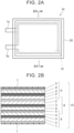
- FIGS. 2A and 2B are diagrams illustrating a schematic configuration of the unit cell 10 according to the present embodiment.
- FIG. 2A is a top view of the unit cell 10.
- the unit cell 10 is a laminated all-solid-state battery using a laminate film as an exterior member 20.
- a negative electrode terminal (negative electrode tab) 1a and a positive electrode terminal (positive electrode tab) 5a protrude from the exterior member 20.
- the laminate film may be, for example, a pouch made of an aluminum laminate film, or may be a three-layer film in which an aluminum foil is sandwiched between a plurality of resin films.
- FIG. 2B shows an all-solid-state battery stack 15 housed in the exterior member 20, and shows an IIB-IIB cross-section of FIG. 2A .
- the all-solid-state battery stack 15 includes, for example, three all-solid-state battery elements 8 in which a negative electrode current collector layer 1, a negative electrode active material layer 2, a solid electrolyte layer 3, a positive electrode active material layer 4, and a positive electrode current collector layer 5 are stacked in this order in each all-solid-state battery element 8. Three all-solid-state battery elements 8 are stacked on each other. Adjacent all-solid-state battery elements 8 share the negative electrode current collector layer 1 or the positive electrode current collector layer 5.
- the stacking order of the negative electrode current collector layer 1, the negative electrode active material layer 2, the solid electrolyte layer 3, the positive electrode active material layer 4, and the positive electrode current collector layer 5 is opposite in adjacent all-solid-state battery elements 8.
- the negative electrode current collector layer 1 is connected to the negative electrode terminal 1a.
- the positive electrode current collector layer 5 is connected to the positive electrode terminal 5a.
- the number of all-solid-state battery elements 8 included in the all-solid-state battery stack 15 may be one, or may be four or more.
- An insulating film 7 provides insulation between the all-solid-state battery stack 15 and the exterior member (laminate film) 20.
- the unit cell 10 is a sulfide-based all-solid-state battery.
- a sulfide-based all-solid-state battery contains a sulfur component in at least one of the material of the positive electrode active material layer 4 and the material of the solid electrolyte layer 3.
- the solid electrolyte layer 3 contains a sulfide-based solid electrolyte.
- the sulfide-based solid electrolyte may use phosphorus pentasulfide (P 2 S 5 ) and lithium sulfide (Li 2 S) as starting materials.
- the positive electrode active material layer 4 may contain, for example, lithium cobalt oxide, lithium nickel oxide, lithium iron phosphate, and the like.
- the positive electrode active material layer 4 is made of a sulfur-based positive electrode active material.
- the sulfur-based positive electrode active material may be an organic sulfur compound or an inorganic sulfur compound. Note that both the solid electrolyte layer 3 and the positive electrode active material layer 4 may contain the sulfur component.
- FIGS. 3A and 3B are diagrams illustrating a method of stacking the unit cells 10.
- the unit cell 10 is shaped in a flat plate, and as shown in FIG. 3A , the unit cells 10 may be stacked such that the exterior member 20 of the unit cells 10 are in contact with each other. Also, the unit cells 10 may be stacked with flat plate-shaped spacers (not shown) interposed between the unit cells 10. Note that, as shown in FIG. 3B , a pair of frame pairs 81 and 82 having inner surfaces corresponding to the outer shape of the unit cell 10 may be used to cover the unit cell 10, and the unit cells 10 covered with the pair of frame pairs 81 and 82 may be stacked with each other.
- an intermediate plate 60 is disposed between the unit cell 10 and the unit cell 10 at the central portion in the stacking direction of the unit cells 10.
- the unit cells 10 and the intermediate plate 60 are sandwiched between the pair of end plates 31 and 32 in a stacked state.
- a predetermined binding load is applied to the unit cells 10, the intermediate plate 60, and the pair of end plates 31 and 32 by a binding band 80, for example.
- the pair of end plates 31 and 32 is fixed to a bottom plate 50 by brackets 41 and 42. Note that, the pair of end plates 31 and 32 is an example of "a pair of restraining members" in the present disclosure.
- the intermediate plate 60 is fixed by being fitted into a groove 51 formed in the bottom plate 50. Thereby, the intermediate plate 60 is fixed to the bottom plate 50 in a cantilevered state.
- a strain gauge 70 is provided on the intermediate plate 60.
- the strain gauge 70 may be a foil strain gauge or a semiconductor strain gauge.
- the strain gauge 70 detects a bending strain of the intermediate plate 60.
- the battery module 200 includes the unit cells 10 and the intermediate plate 60, which are stacked between the pair of end plates 31 and 32, the bottom plate 50, and the like.
- the battery module 200 is fixed to a battery case 90.
- the battery case 90 is a housing that accommodates the battery module 200.
- the control device 300 includes a processor such as a central processing unit (CPU), a memory such as a read only memory (ROM) and a random access memory (RAM), an input/output port, and the like, and controls charging and discharging of the battery module 200.
- the control device 300 estimates the generation of hydrogen sulfide (H 2 S) in the unit cell 10 based on a detection signal of the strain gauge 70.
- the control device 300 functions as an "estimation unit" of the present disclosure.
- FIG. 4 is a flowchart showing an example of a hydrogen sulfide generation estimation process executed by the control device 300. This flowchart is repeatedly processed every predetermined period.
- step (hereinafter abbreviated as "S") 10 based on the detection signal of the strain gauge 70, a change amount of the load L (load change amount) ⁇ L applied to the intermediate plate 60 is acquired.
- any one of the unit cells 10 of the battery module 200 for some reason, when the sulfur component contained in the solid electrolyte layer 3 or the positive electrode active material layer 4 reacts with moisture to generate hydrogen sulfide, a volume of the unit cell 10 increases by the gas pressure.
- the load applied to the intermediate plate 60 changes.
- a force Fa acts on the intermediate plate 60 in the direction indicated by a continuous line arrow.
- a force Fb acts on the intermediate plate 60 in the direction indicated by a dotted line arrow.
- S12 it is determined that hydrogen sulfide is generated in the unit cell 10, and the current routine ends.
- an arrangement position of the unit cell 10 where hydrogen sulfide is generated can also be identified. For example, as shown in FIG. 1 , in the case where the strain gauge 70 is provided on the left side surface of the intermediate plate 60, the strain gauge 70 outputs the detection signal in the direction of tension (elongation direction) when the force Fa acts on the intermediate plate 60, and the strain gauge 70 outputs the detection signal in the direction of compression (contraction direction) when the force Fb acts on the intermediate plate 60.
- the detection signal of the strain gauge 70 when the detection signal of the strain gauge 70 is in the direction of tension, it can be determined that hydrogen sulfide is generated in any one of the unit cells 10 on the left side of the intermediate plate 60.
- the detection signal of the strain gauge 70 when the detection signal of the strain gauge 70 is in the direction of compression, it can be determined that hydrogen sulfide is generated in any one of the unit cells 10 on the right side of the intermediate plate 60.
- the change in the load applied to the intermediate plate 60 is detected by the bending strain detected by the strain gauge 70 provided on the intermediate plate 60 disposed between the stacked unit cells 10. Since the generation of hydrogen sulfide in the unit cell 10 is estimated based on the change in the load applied to the intermediate plate 60, hydrogen sulfide generated in the unit cell 10 can be detected before the battery case 90 is filled with hydrogen sulfide.
- the pair of end plates 31 and 32 and the intermediate plate 60 are fixed to the bottom plate 50.
- the pair of end plates 31 and 32 and the intermediate plate 60 may be directly fixed to the battery case 90. Modifications
- FIG. 5 is a diagram showing a schematic configuration of a battery module 200a in a modification.
- an intermediate plate 61 located in the central portion of a plurality of stacked unit cells 10 is not fixed to a bottom plate 55. Therefore, the intermediate plate 61 can be displaced (or moved) in the stacking direction of the unit cells 10.
- a displacement sensor (displacement gauge) 71 is provided in a portion of a bottom plate 55 facing the intermediate plate 61.
- the displacement sensor 71 may be a variable resistance displacement sensor of which resistance changes according to the displacement of the intermediate plate 61, or may be a non-contact linear displacement sensor using the Hall effect.
- any one of the unit cells 10 of the battery module 200 for some reason, when the sulfur component contained in a solid electrolyte layer 3 or a positive electrode active material layer 4 reacts with moisture to generate hydrogen sulfide, a volume of the unit cell 10 increases by gas pressure. As the volume of the unit cell 10 increases, the load applied to the intermediate plate 61 changes.
- a force Fa acts on the intermediate plate 61 in the direction indicated by a continuous line arrow.
- a force Fb acts on the intermediate plate 61 in the direction indicated by a dotted line arrow.
- the change in the load applied to the intermediate plate 61 is detected from the displacement detected by the displacement sensor 71 that detects the displacement of the intermediate plate 61 disposed between the stacked unit cells 10. Since the generation of hydrogen sulfide in the unit cell 10 is estimated based on the change in the load applied to the intermediate plate 61, hydrogen sulfide generated in the unit cell 10 can be detected before the battery case 90 is filled with hydrogen sulfide.
- the intermediate plate 60 including the strain gauge 70 or a combination of the intermediate plate 61 and the displacement sensor 71 is provided at the central portion in the stacking direction of the unit cells 10.
- these positions are not limited to the central portion.
- a plurality of intermediate plates 60 may be disposed, for example, at equal intervals in the stacking direction of the unit cells 10.
- a plurality of combinations of the intermediate plate 61 and the displacement sensor 71 may be disposed at equal intervals in the stacking direction of the unit cells 10, for example.
- both the intermediate plate 60 provided with the strain gauge 70 and the combination of the intermediate plate 61 and the displacement sensor 71 may be provided in one battery module with a space therebetween.
- the battery system 100 may be mounted on an electrified vehicle or may be stationary.
Landscapes
- Chemical & Material Sciences (AREA)
- Chemical Kinetics & Catalysis (AREA)
- Electrochemistry (AREA)
- General Chemical & Material Sciences (AREA)
- Engineering & Computer Science (AREA)
- Manufacturing & Machinery (AREA)
- General Physics & Mathematics (AREA)
- Physics & Mathematics (AREA)
- Inorganic Chemistry (AREA)
- Condensed Matter Physics & Semiconductors (AREA)
- Materials Engineering (AREA)
- Secondary Cells (AREA)
- Battery Mounting, Suspending (AREA)
Priority Applications (1)
| Application Number | Priority Date | Filing Date | Title |
|---|---|---|---|
| EP25172025.6A EP4683039A3 (de) | 2023-01-24 | 2023-12-07 | Batteriesystem |
Applications Claiming Priority (1)
| Application Number | Priority Date | Filing Date | Title |
|---|---|---|---|
| JP2023008609A JP7729356B2 (ja) | 2023-01-24 | 2023-01-24 | 電池システム |
Related Child Applications (1)
| Application Number | Title | Priority Date | Filing Date |
|---|---|---|---|
| EP25172025.6A Division EP4683039A3 (de) | 2023-01-24 | 2023-12-07 | Batteriesystem |
Publications (2)
| Publication Number | Publication Date |
|---|---|
| EP4407729A2 true EP4407729A2 (de) | 2024-07-31 |
| EP4407729A3 EP4407729A3 (de) | 2024-10-23 |
Family
ID=89122012
Family Applications (2)
| Application Number | Title | Priority Date | Filing Date |
|---|---|---|---|
| EP23215064.9A Pending EP4407729A3 (de) | 2023-01-24 | 2023-12-07 | Batteriesystem |
| EP25172025.6A Pending EP4683039A3 (de) | 2023-01-24 | 2023-12-07 | Batteriesystem |
Family Applications After (1)
| Application Number | Title | Priority Date | Filing Date |
|---|---|---|---|
| EP25172025.6A Pending EP4683039A3 (de) | 2023-01-24 | 2023-12-07 | Batteriesystem |
Country Status (5)
| Country | Link |
|---|---|
| US (1) | US20240247990A1 (de) |
| EP (2) | EP4407729A3 (de) |
| JP (1) | JP7729356B2 (de) |
| KR (1) | KR20240117034A (de) |
| CN (1) | CN118398933A (de) |
Citations (1)
| Publication number | Priority date | Publication date | Assignee | Title |
|---|---|---|---|---|
| JP2022046077A (ja) | 2020-09-10 | 2022-03-23 | 日産自動車株式会社 | 電池システム及び電池の冷却方法 |
Family Cites Families (9)
| Publication number | Priority date | Publication date | Assignee | Title |
|---|---|---|---|---|
| JP2002289265A (ja) * | 2001-03-23 | 2002-10-04 | Mitsubishi Heavy Ind Ltd | リチウム二次電池の監視装置 |
| JP2006269345A (ja) * | 2005-03-25 | 2006-10-05 | Nec Lamilion Energy Ltd | 過電圧検出方法、装置及びバッテリパック |
| JP2010165585A (ja) * | 2009-01-16 | 2010-07-29 | Toyota Motor Corp | 蓄電装置 |
| WO2011055429A1 (ja) * | 2009-11-04 | 2011-05-12 | トヨタ自動車株式会社 | 電池及び電池システム |
| WO2011074097A1 (ja) * | 2009-12-17 | 2011-06-23 | トヨタ自動車株式会社 | 硫化物系固体電解質電池セル、当該電池セルを備える電池パック、当該電池パックを備える車両システム及び硫化水素検知方法 |
| JP6184938B2 (ja) * | 2014-12-25 | 2017-08-23 | 本田技研工業株式会社 | 蓄電モジュールが搭載される電動車両 |
| HUE071136T2 (hu) * | 2020-03-27 | 2025-08-28 | Samsung Sdi Co Ltd | Fluidumrugóval nyomás alá helyezett akkumulátorköteg |
| JP2022014295A (ja) * | 2020-07-06 | 2022-01-19 | トヨタ自動車株式会社 | 全固体電池パック |
| JP2022159809A (ja) * | 2021-04-05 | 2022-10-18 | 古河電気工業株式会社 | バイポーラ型蓄電池、及び組蓄電池装置 |
-
2023
- 2023-01-24 JP JP2023008609A patent/JP7729356B2/ja active Active
- 2023-11-27 CN CN202311598266.6A patent/CN118398933A/zh active Pending
- 2023-12-01 KR KR1020230172063A patent/KR20240117034A/ko active Pending
- 2023-12-01 US US18/525,937 patent/US20240247990A1/en active Pending
- 2023-12-07 EP EP23215064.9A patent/EP4407729A3/de active Pending
- 2023-12-07 EP EP25172025.6A patent/EP4683039A3/de active Pending
Patent Citations (1)
| Publication number | Priority date | Publication date | Assignee | Title |
|---|---|---|---|---|
| JP2022046077A (ja) | 2020-09-10 | 2022-03-23 | 日産自動車株式会社 | 電池システム及び電池の冷却方法 |
Also Published As
| Publication number | Publication date |
|---|---|
| EP4683039A3 (de) | 2026-02-25 |
| EP4407729A3 (de) | 2024-10-23 |
| JP2024104421A (ja) | 2024-08-05 |
| US20240247990A1 (en) | 2024-07-25 |
| EP4683039A2 (de) | 2026-01-21 |
| CN118398933A (zh) | 2024-07-26 |
| KR20240117034A (ko) | 2024-07-31 |
| JP7729356B2 (ja) | 2025-08-26 |
Similar Documents
| Publication | Publication Date | Title |
|---|---|---|
| US12092698B2 (en) | Degradation-determination system and method for determining degradation of secondary battery | |
| US10003203B2 (en) | All-solid-state secondary battery system | |
| JP5067302B2 (ja) | 充電深度計測機構及び計測方法、並びに該計測機構を備える二次電池 | |
| US20160093844A1 (en) | Battery stack | |
| EP3806180B1 (de) | Batteriemodul | |
| EP4318730B1 (de) | Stosstestvorrichtung für beutelartige batteriezelle und stosstestverfahren für beutelartige batteriezelle damit | |
| EP4407729A2 (de) | Batteriesystem | |
| JP5693302B2 (ja) | 電池システム | |
| US12057543B2 (en) | Battery cell manufacturing device | |
| JP2007066612A (ja) | 電池構造および電池モジュール | |
| EP4009417B1 (de) | Beutelförmige sekundärbatterie mit druckmessvorrichtung zur messung des innendrucks | |
| JP7639800B2 (ja) | 蓄電デバイス | |
| JP2024131787A (ja) | 検査装置 | |
| JP2019200931A (ja) | 蓄電装置 | |
| JP7713980B2 (ja) | 蓄電デバイス及びスタック | |
| CN114597337A (zh) | 一种电池极片以及动力电池 | |
| CN113451666A (zh) | 电池系统及其操作方法以及包括其的电池组和车辆 | |
| JP2020166975A (ja) | 電池モジュール | |
| JP7605991B2 (ja) | 熱暴走感知用の圧力センサーを備えるバッテリーモジュール | |
| US20240145800A1 (en) | Battery pack | |
| JP2019200933A (ja) | 蓄電装置 | |
| KR20250030830A (ko) | 배터리 모듈 및 이를 포함하는 배터리 팩 |
Legal Events
| Date | Code | Title | Description |
|---|---|---|---|
| PUAI | Public reference made under article 153(3) epc to a published international application that has entered the european phase |
Free format text: ORIGINAL CODE: 0009012 |
|
| STAA | Information on the status of an ep patent application or granted ep patent |
Free format text: STATUS: REQUEST FOR EXAMINATION WAS MADE |
|
| 17P | Request for examination filed |
Effective date: 20240106 |
|
| AK | Designated contracting states |
Kind code of ref document: A2 Designated state(s): AL AT BE BG CH CY CZ DE DK EE ES FI FR GB GR HR HU IE IS IT LI LT LU LV MC ME MK MT NL NO PL PT RO RS SE SI SK SM TR |
|
| PUAL | Search report despatched |
Free format text: ORIGINAL CODE: 0009013 |
|
| AK | Designated contracting states |
Kind code of ref document: A3 Designated state(s): AL AT BE BG CH CY CZ DE DK EE ES FI FR GB GR HR HU IE IS IT LI LT LU LV MC ME MK MT NL NO PL PT RO RS SE SI SK SM TR |
|
| RIC1 | Information provided on ipc code assigned before grant |
Ipc: H01M 10/48 20060101ALI20240918BHEP Ipc: H01M 10/0562 20100101ALI20240918BHEP Ipc: H01M 10/04 20060101AFI20240918BHEP |
|
| GRAP | Despatch of communication of intention to grant a patent |
Free format text: ORIGINAL CODE: EPIDOSNIGR1 |
|
| STAA | Information on the status of an ep patent application or granted ep patent |
Free format text: STATUS: GRANT OF PATENT IS INTENDED |
|
| INTG | Intention to grant announced |
Effective date: 20260220 |