EP4407723A2 - Brennstoffzellen-gruppierungsvorrichtung mit einem träger zur versorgung der brennstoffzellen mit fluid, flugzeug mit mindestens einer solchen brennstoffzellen-gruppierungsvorrichtung - Google Patents
Brennstoffzellen-gruppierungsvorrichtung mit einem träger zur versorgung der brennstoffzellen mit fluid, flugzeug mit mindestens einer solchen brennstoffzellen-gruppierungsvorrichtung Download PDFInfo
- Publication number
- EP4407723A2 EP4407723A2 EP24174130.5A EP24174130A EP4407723A2 EP 4407723 A2 EP4407723 A2 EP 4407723A2 EP 24174130 A EP24174130 A EP 24174130A EP 4407723 A2 EP4407723 A2 EP 4407723A2
- Authority
- EP
- European Patent Office
- Prior art keywords
- casing
- fuel cells
- fluid
- grouping device
- collector
- Prior art date
- Legal status (The legal status is an assumption and is not a legal conclusion. Google has not performed a legal analysis and makes no representation as to the accuracy of the status listed.)
- Pending
Links
Images




Classifications
-
- H—ELECTRICITY
- H01—ELECTRIC ELEMENTS
- H01M—PROCESSES OR MEANS, e.g. BATTERIES, FOR THE DIRECT CONVERSION OF CHEMICAL ENERGY INTO ELECTRICAL ENERGY
- H01M8/00—Fuel cells; Manufacture thereof
- H01M8/24—Grouping of fuel cells, e.g. stacking of fuel cells
- H01M8/249—Grouping of fuel cells, e.g. stacking of fuel cells comprising two or more groupings of fuel cells, e.g. modular assemblies
-
- H—ELECTRICITY
- H01—ELECTRIC ELEMENTS
- H01M—PROCESSES OR MEANS, e.g. BATTERIES, FOR THE DIRECT CONVERSION OF CHEMICAL ENERGY INTO ELECTRICAL ENERGY
- H01M8/00—Fuel cells; Manufacture thereof
- H01M8/24—Grouping of fuel cells, e.g. stacking of fuel cells
- H01M8/2465—Details of groupings of fuel cells
- H01M8/2484—Details of groupings of fuel cells characterised by external manifolds
-
- B—PERFORMING OPERATIONS; TRANSPORTING
- B64—AIRCRAFT; AVIATION; COSMONAUTICS
- B64D—EQUIPMENT FOR FITTING IN OR TO AIRCRAFT; FLIGHT SUITS; PARACHUTES; ARRANGEMENT OR MOUNTING OF POWER PLANTS OR PROPULSION TRANSMISSIONS IN AIRCRAFT
- B64D27/00—Arrangement or mounting of power plants in aircraft; Aircraft characterised by the type or position of power plants
- B64D27/02—Aircraft characterised by the type or position of power plants
- B64D27/24—Aircraft characterised by the type or position of power plants using steam or spring force
-
- B—PERFORMING OPERATIONS; TRANSPORTING
- B64—AIRCRAFT; AVIATION; COSMONAUTICS
- B64D—EQUIPMENT FOR FITTING IN OR TO AIRCRAFT; FLIGHT SUITS; PARACHUTES; ARRANGEMENT OR MOUNTING OF POWER PLANTS OR PROPULSION TRANSMISSIONS IN AIRCRAFT
- B64D27/00—Arrangement or mounting of power plants in aircraft; Aircraft characterised by the type or position of power plants
- B64D27/02—Aircraft characterised by the type or position of power plants
- B64D27/30—Aircraft characterised by electric power plants
- B64D27/35—Arrangements for on-board electric energy production, distribution, recovery or storage
- B64D27/355—Arrangements for on-board electric energy production, distribution, recovery or storage using fuel cells
-
- B—PERFORMING OPERATIONS; TRANSPORTING
- B64—AIRCRAFT; AVIATION; COSMONAUTICS
- B64D—EQUIPMENT FOR FITTING IN OR TO AIRCRAFT; FLIGHT SUITS; PARACHUTES; ARRANGEMENT OR MOUNTING OF POWER PLANTS OR PROPULSION TRANSMISSIONS IN AIRCRAFT
- B64D41/00—Power installations for auxiliary purposes
-
- B—PERFORMING OPERATIONS; TRANSPORTING
- B64—AIRCRAFT; AVIATION; COSMONAUTICS
- B64U—UNMANNED AERIAL VEHICLES [UAV]; EQUIPMENT THEREFOR
- B64U50/00—Propulsion; Power supply
- B64U50/30—Supply or distribution of electrical power
- B64U50/32—Supply or distribution of electrical power generated by fuel cells
-
- H—ELECTRICITY
- H01—ELECTRIC ELEMENTS
- H01M—PROCESSES OR MEANS, e.g. BATTERIES, FOR THE DIRECT CONVERSION OF CHEMICAL ENERGY INTO ELECTRICAL ENERGY
- H01M8/00—Fuel cells; Manufacture thereof
- H01M8/04—Auxiliary arrangements, e.g. for control of pressure or for circulation of fluids
- H01M8/04082—Arrangements for control of reactant parameters, e.g. pressure or concentration
- H01M8/04089—Arrangements for control of reactant parameters, e.g. pressure or concentration of gaseous reactants
- H01M8/04119—Arrangements for control of reactant parameters, e.g. pressure or concentration of gaseous reactants with simultaneous supply or evacuation of electrolyte; Humidifying or dehumidifying
- H01M8/04156—Arrangements for control of reactant parameters, e.g. pressure or concentration of gaseous reactants with simultaneous supply or evacuation of electrolyte; Humidifying or dehumidifying with product water removal
-
- H—ELECTRICITY
- H01—ELECTRIC ELEMENTS
- H01M—PROCESSES OR MEANS, e.g. BATTERIES, FOR THE DIRECT CONVERSION OF CHEMICAL ENERGY INTO ELECTRICAL ENERGY
- H01M8/00—Fuel cells; Manufacture thereof
- H01M8/24—Grouping of fuel cells, e.g. stacking of fuel cells
- H01M8/2404—Processes or apparatus for grouping fuel cells
-
- H—ELECTRICITY
- H01—ELECTRIC ELEMENTS
- H01M—PROCESSES OR MEANS, e.g. BATTERIES, FOR THE DIRECT CONVERSION OF CHEMICAL ENERGY INTO ELECTRICAL ENERGY
- H01M8/00—Fuel cells; Manufacture thereof
- H01M8/24—Grouping of fuel cells, e.g. stacking of fuel cells
- H01M8/2465—Details of groupings of fuel cells
-
- H—ELECTRICITY
- H01—ELECTRIC ELEMENTS
- H01M—PROCESSES OR MEANS, e.g. BATTERIES, FOR THE DIRECT CONVERSION OF CHEMICAL ENERGY INTO ELECTRICAL ENERGY
- H01M8/00—Fuel cells; Manufacture thereof
- H01M8/24—Grouping of fuel cells, e.g. stacking of fuel cells
- H01M8/2465—Details of groupings of fuel cells
- H01M8/247—Arrangements for tightening a stack, for accommodation of a stack in a tank or for assembling different tanks
- H01M8/2475—Enclosures, casings or containers of fuel cell stacks
-
- H—ELECTRICITY
- H01—ELECTRIC ELEMENTS
- H01M—PROCESSES OR MEANS, e.g. BATTERIES, FOR THE DIRECT CONVERSION OF CHEMICAL ENERGY INTO ELECTRICAL ENERGY
- H01M8/00—Fuel cells; Manufacture thereof
- H01M8/24—Grouping of fuel cells, e.g. stacking of fuel cells
- H01M8/2465—Details of groupings of fuel cells
- H01M8/2483—Details of groupings of fuel cells characterised by internal manifolds
-
- H—ELECTRICITY
- H01—ELECTRIC ELEMENTS
- H01M—PROCESSES OR MEANS, e.g. BATTERIES, FOR THE DIRECT CONVERSION OF CHEMICAL ENERGY INTO ELECTRICAL ENERGY
- H01M8/00—Fuel cells; Manufacture thereof
- H01M8/24—Grouping of fuel cells, e.g. stacking of fuel cells
- H01M8/2465—Details of groupings of fuel cells
- H01M8/2484—Details of groupings of fuel cells characterised by external manifolds
- H01M8/2485—Arrangements for sealing external manifolds; Arrangements for mounting external manifolds around a stack
-
- B—PERFORMING OPERATIONS; TRANSPORTING
- B64—AIRCRAFT; AVIATION; COSMONAUTICS
- B64D—EQUIPMENT FOR FITTING IN OR TO AIRCRAFT; FLIGHT SUITS; PARACHUTES; ARRANGEMENT OR MOUNTING OF POWER PLANTS OR PROPULSION TRANSMISSIONS IN AIRCRAFT
- B64D41/00—Power installations for auxiliary purposes
- B64D2041/005—Fuel cells
-
- H—ELECTRICITY
- H01—ELECTRIC ELEMENTS
- H01M—PROCESSES OR MEANS, e.g. BATTERIES, FOR THE DIRECT CONVERSION OF CHEMICAL ENERGY INTO ELECTRICAL ENERGY
- H01M2250/00—Fuel cells for particular applications; Specific features of fuel cell system
- H01M2250/20—Fuel cells in motive systems, e.g. vehicle, ship, plane
-
- Y—GENERAL TAGGING OF NEW TECHNOLOGICAL DEVELOPMENTS; GENERAL TAGGING OF CROSS-SECTIONAL TECHNOLOGIES SPANNING OVER SEVERAL SECTIONS OF THE IPC; TECHNICAL SUBJECTS COVERED BY FORMER USPC CROSS-REFERENCE ART COLLECTIONS [XRACs] AND DIGESTS
- Y02—TECHNOLOGIES OR APPLICATIONS FOR MITIGATION OR ADAPTATION AGAINST CLIMATE CHANGE
- Y02E—REDUCTION OF GREENHOUSE GAS [GHG] EMISSIONS, RELATED TO ENERGY GENERATION, TRANSMISSION OR DISTRIBUTION
- Y02E60/00—Enabling technologies; Technologies with a potential or indirect contribution to GHG emissions mitigation
- Y02E60/30—Hydrogen technology
- Y02E60/50—Fuel cells
Definitions
- a fuel cell is a device generating an electrical voltage through the oxidation on one electrode of a reducing fuel, such as hydrogen for example, coupled with the reduction on another electrode of an oxidant, such as oxygen air for example.
- a fuel cell 10 comprises first inlets and outlets 12.1, 12.2 for a first fluid, in particular the fuel, second inlets and outlets 14.1, 14.2 for a second fluid, in particular the oxidant, as well as third inlets and outlets 16.1 , 16.2 for a third fluid, in particular a cooling fluid.
- the first inlets and outlets 12.1, 12.2 intended for the first fluid are connected to a first circuit 12 which includes a supply of first fluid 20.1 as well as different equipment such as a first water extraction system 20.2, a pump recirculation 20.3, a first flow management system 20.4 and a draining system 20.5 for example.
- a first circuit 12 which includes a supply of first fluid 20.1 as well as different equipment such as a first water extraction system 20.2, a pump recirculation 20.3, a first flow management system 20.4 and a draining system 20.5 for example.
- the second inlets and outlets 14.1, 14.2, intended for the second fluid are connected to a second circuit 14 which includes a supply of second fluid 22.1 as well as various equipment such as a dehumidification system 22.2, a second flow management system 22.3 and a second water extraction system 22.4 for example.
- the third inlet and outlet 16.1, 16.2, intended for the third fluid are connected to a third circuit 16 which includes a heat exchanger 24.1 configured to regulate the temperature of the third fluid.
- the present invention aims to remedy all or part of the drawbacks of the prior art.
- the subject of the invention is a fuel cell grouping device comprising at least two fuel cells in which at least a first fluid circulates, characterized in that the grouping device comprises a support as well as at least a portion of a first circuit for the first fluid comprising a first feeder configured to supply the first fluid to the fuel cells and a first collector configured to collect the first fluid from the fuel cells, the support comprising a casing, the first feeder and the first collector being integral with the casing and positioned between the casing and the fuel cells.
- Such a grouping device can be moved or manipulated in one piece. It also makes it possible to limit the number of attachment points on a primary structure of an aircraft. Positioning the first feeder and the first collector between the casing and the fuel cells makes it possible to obtain a more compact assembly.
- each casing comprises at least one external shoulder extending over at least part of its periphery.
- the shoulder makes it possible to transfer the loads of the assembly towards the structure on which the shoulder rests and as seen below in particular the primary structure of 'an aircraft.
- the shoulder extends over the entire periphery of the device.
- the casing comprises at least one opening configured to cooperate with at least one of the fuel cells and crossed by conduits connected to the fuel cell.
- the casing comprises a bottom, two transverse walls as well as two longitudinal walls which delimit a housing configured to accommodate at least one feeder among the first, second and third feeders as well as at least one collector among the first, second and third collectors.
- the transverse and longitudinal walls comprise upper edges which form a belt surrounding the fuel cells in operation.
- the casing comprises at least one interior shoulder offset towards the bottom relative to the upper edges of the transverse and longitudinal walls, said interior shoulder forming a contact surface for the fuel cells.
- the casing for each first, second or third feeder or collector positioned between the casing and the fuel cells, the casing comprises a first or second through orifice configured to accommodate a feed or exhaust conduit from the feeder or of the collector or a conduit extending the supply or exhaust conduit of the tank or the collector.
- the casing comprises a third or fourth through orifice for each outlet or inlet conduit of the feeder or collector, each third or fourth through orifice being configured to accommodate one of the outlet or inlet conduits of the feeder or collector or a conduit extending one of the outlet or inlet conduits of the feeder or collector.
- the grouping device comprises at least one piece of equipment for at least one fluid circuit comprising first and second parts connected in a removable manner by connecting elements, at least one of the first and second parts being integral and integrated into the housing.
- the grouping device being movable or manipulated in one piece, it is possible to intervene easily and quickly on a removable part in which we provides for example elements on which more regular or more complex maintenance is to be carried out.
- the removable part is an active part.
- the equipment is a valve and the removable part comprises controlling the flow of fluid between an upstream and downstream part included in the part integrated into the casing.
- equipment is a water extraction system and the active part comprises a valve allowing the water created by the extraction system to be purged.
- the invention also relates to an aircraft comprising a primary structure as well as at least one device for grouping fuel cells according to one of the preceding characteristics.
- the aircraft comprises at least one chassis connected to the primary structure of the aircraft for each grouping device, the chassis comprising a frame configured to allow the insertion of the fuel cells of the grouping device and against which supports the casing.
- each casing comprises at least one external shoulder extending over at least part of its periphery and configured to bear against one of the frames of the chassis to transfer the loads from the casing to the primary structure.
- a peripheral seal is inserted between the outer shoulder of the casing and the frame of the chassis.
- a fuel cell grouping device 30 comprises several fuel cells 32 each comprising first inlets and outlets 34.1, 34.2 for a first fluid, in particular a fuel, second inlets and outlets 36.1, 36.2 for a second fluid, in particular an oxidant , as well as third inlets and outlets 38.1, 38.2 for a third fluid, in particular a cooling fluid.
- the grouping device 30 comprises four fuel cells 32. At a minimum, the grouping device 30 comprises at least two fuel cells 32.
- the first fluid is hydrogen
- the second fluid is air
- the third fluid is a coolant.
- each fuel cell 32 has a parallelepiped shape and has a lower face 32.1 at which the different inputs and outputs 34.1, 34.2, 36.1, 36.2, 38.1, 38.2 are positioned.
- an aircraft comprises a primary structure as well as at least one grouping device 30 connected, directly or indirectly, to the primary structure.
- the grouping device 30 comprises a first feeder 40, intended for the first fluid, which has a supply conduit 40.1 and as many outlet conduits 40.2 as the number of first inlets 34.1 of the fuel cells 32 of the grouping device 30.
- the first feeder 40 comprises four outlet conduits 40.2. More generally, the first feeder 40 is configured to supply the fuel cells 32 of the grouping device 30 with first fluid.
- this first feeder 40 intended for hydrogen, includes a reduction in the passage section, in particular at the level of the outlet conduits 40.2, in order to limit the flow of hydrogen in the event of failure at the level of a connection with one of the first inputs 34.1 of the fuel cells 32.
- This configuration contributes to reinforcing the security of the grouping device 30.
- the grouping device 30 comprises a first collector 42, intended for the first fluid, which has an exhaust conduit 42.1 and as many inlet conduits 42.2 as the number of first outlets 34.2 of the fuel cells 32 of the grouping device 30.
- the first collector 42 comprises four inlet conduits 42.2.
- the first collector 42 is configured to collect the first fluid from the fuel cells 32 of the grouping device 30.
- this first collector 42 intended for hydrogen comprises a reduction in the passage section, in particular at the level inlet conduits 42.2, in order to limit the flow of hydrogen in the event of a failure at a connection with one of the first outlets 34.2 of the fuel cells 32. This configuration contributes to reinforcing the security of the grouping device 30.
- the grouping device 30 comprises a second feeder 44, intended for the second fluid, which has a supply conduit 44.1 and as many outlet conduits 44.2 as the number of second inlets 36.1 of the fuel cells 32 of the grouping device 30. presence of four fuel cells 32, the second feeder 44 comprises four outlet conduits 44.2. More generally, the second feeder 44 is configured to supply the fuel cells 32 of the grouping device 30 with a second fluid.
- the grouping device 30 comprises a second collector 46, intended for the second fluid, which has an exhaust conduit 46.1 and as many inlet conduits 46.2 as the number of second outlets 36.2 of the fuel cells 32 of the grouping device 30.
- the second collector 46 comprises four inlet conduits 46.2. More generally, the second collector 46 is configured to collect the second fluid from the fuel cells 32 of the grouping device 30.
- the grouping device 30 comprises a third feeder 48, intended for the third fluid, which has a supply conduit 48.1 and as many outlet conduits 48.2 as the number of third inlets 38.1 of the fuel cells 32 of the grouping device 30. presence of four fuel cells 32, the third feeder 48 comprises four outlet conduits 48.2. More generally, the third feeder 48 is configured to supply the fuel cells 32 of the grouping device 30 with a third fluid.
- the grouping device 30 comprises a third collector 50, intended for the third fluid, which has an exhaust conduit 50.1 and as many inlet conduits 50.2 as the number of third outlets 38.2 of the fuel cells 32 of the grouping device 30.
- the third collector 50 comprises four inlet conduits 50.2. More generally, the third collector 50 is configured to collect the third fluid from the fuel cells 32 of the grouping device 30.
- the grouping device 30 comprises a first fluid circuit 52 comprising the first feeder 40, the first collector 42, a supply of first fluid 52.1 as well as various pieces of equipment such as a first water extraction system 52.2, a recirculation pump 52.3, a first flow management system 52.4 and a draining system 52.5 for example.
- each grouping device 30 includes its own supply of first fluid 52.1 and its own draining system 52.5.
- a supply of first fluid 52.1 may be common to several grouping devices 30.
- a draining system 52.5 may be common to several grouping devices 30.
- the grouping device 30 comprises a second fluid circuit 54 comprising the second feeder 44, the second collector 46, a second fluid supply 54.1 as well as various pieces of equipment such as a dehumidification system 54.2, a second flow management system 54.3 and a second water extraction system 54.4 for example.
- each grouping device 30 comprises its own supply of second fluid 54.1 and its own water extraction system 54.4.
- a supply of second fluid 54.1 can be common to several grouping devices 30.
- a water extraction system 54.4 can be common to several grouping devices 30.
- the grouping device 30 comprises a third fluid circuit 56 comprising the third feeder 48, the third collector 50 as well as at least one heat exchanger 56.1 configured to regulate the temperature of the third fluid.
- each grouping device 30 comprises its own heat exchanger 56.1.
- a heat exchanger 56.1 can be common to several grouping devices 30.
- the grouping device 30 comprises a support 58, positioned at the level of the lower faces 32.1 of the fuel cells 32 of the grouping device 30, which comprises at least one casing 60, at least one feeder among the first, second and third feeders 40, 44, 48 positioned between the casing 60 and the fuel cells 32, at least one collector among the first, second and third collectors 42, 46, 50 positioned between the casing 60 and the fuel cells 32.
- the casing 60, the first, second and third feeders 40, 44, 48 as well as the first, second and third collectors 42, 46, 50 are separate parts. According to another configuration, at least one element among the first, second and third feeders 40, 44, 48 as well as the first, second and third collectors 42, 46, 50 is integrated into the casing 60 and forms only a single and same part with casing 60.
- the feeder and the collector of the same fluid are located between the casing 60 and the fuel cells 32 or outside a zone between the casing 60 and the fuel cells 32.
- the grouping device 30 comprises first, second and third feeders 40, 44, 48 as well as first, second and third collectors 42, 46, 50 positioned between the casing 60 and the fuel cells 32.
- the grouping device 30 comprises first and third feeders 40, 48 as well as first and third collectors 42, 50 positioned between the casing and the fuel cells 32, the first feeder and the first collector 40, 42 being intended for the first fluid (hydrogen), the third feeder and the third collector 48, 50 being intended for the third fluid (cooling fluid).
- Each first, second or third feeder 40, 44, 48 and/or each first, second or third collector 42, 46, 48 positioned between the casing 60 and the fuel cells 32 is supported by the casing 60 and fixed to the latter. This arrangement makes it possible to reduce the number of attachment points on the primary structure of the aircraft.
- each first, second or third nurse 40, 44, 48 and/or each first, second or third collector 42, 46, 48 positioned outside the casing 60 is fixed to this last. This arrangement makes it possible to reduce the number of attachment points on the primary structure of the aircraft.
- the casing 60 comprises a first through orifice 62 configured to communicate the interior and exterior of the casing and house the supply conduit 40.1, 44.1, 48.1 of the reservoir 40, 44, 48 or a conduit extending the supply conduit 40.1, 44.1, 48.1 of the reservoir 40, 44, 48.
- the casing 60 comprises a second through orifice 64 configured to communicate the interior and exterior of the casing 60 and accommodate the exhaust conduit 42.1, 46.1, 50.1 of the collector 42, 46, 48 or a conduit extending the exhaust conduit 42.1, 46.1, 50.1 of the collector 42, 46, 48.
- the casing 60 For each first, second or third feeder 40, 44, 48 which is not positioned between the casing 60 and the fuel cells 32, the casing 60 comprises a third through orifice 66 for each outlet conduit 40.2, 44.2, 48.2 of the feeder 40, 44, 48, as illustrated on the figures 6 And 7 , each third through orifice 64 being configured to accommodate one of the outlet conduits 40.2, 44.2, 48.2 of the feeder 40, 44, 48 or a conduit extending one of the outlet conduits 40.2, 44.2, 48.2 of the feeder 40, 44, 48 .
- the casing 60 For each first, second or third collector 42, 46, 48 which is not positioned between the casing 60 and the fuel cells 32, the casing 60 comprises a fourth through hole 67 for each inlet conduit 42.2, 46.2, 50.2 of the collector 42, 46, 48, as illustrated in the figure 7 , each fourth through orifice 67 being configured to accommodate one of the inlet conduits 42.2, 46.2, 50.2 of the collector 42, 46, 48 or a conduit extending one of the inlet conduits 42.2, 46.2, 50.21 of the collector 42, 46, 48 .
- the fuel cells 32 are closely spaced in a horizontal plane and aligned in a longitudinal direction, their lower faces 32.1 being substantially coplanar.
- each of the fuel cells could be positioned on top of each other and be closely spaced in a vertical direction.
- each of the fuel cells comprises a side face coplanar with a side face of each of the other fuel cells and the support 58 is positioned at the level of these side faces.
- the fuel cells 32 of the grouping device 30 have a rectangular section in a plane parallel to the lower faces 32.1, with a first dimension in the longitudinal direction and a second dimension in a transverse direction perpendicular to the longitudinal direction.
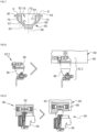
- the casing 60 has a bottom 68, two transverse walls 70, 72 as well as two longitudinal walls 74, 76 which delimit a housing 78, substantially sealed, configured to accommodate at least one feeder among the first, second and third feeders 40, 44, 48 as well as at least one collector among the first, second and third collectors 42, 46, 50.
- the housing 78 is partially closed by the fuel cells 32 when the latter are connected to the casing 60.
- the casing 60 n is not limited to this geometry.
- the casing 60 may have a more or less complex shape which has at least one opening configured to cooperate with at least one of the fuel cells 32, said opening being crossed by conduits connected to the fuel cell 32.
- the casing 60 could be closed by a panel on its upper face.
- transverse and longitudinal walls 70, 72, 74, 76 comprise upper edges E which form a belt 80 surrounding the fuel cells 32 in operation.
- This belt 80 is substantially rectangular in top view and has a length slightly greater than the first dimension as well as a width substantially equal to the second dimension.
- the casing 60 comprises at least one interior shoulder 82 offset towards the bottom 68 relative to the upper edges E of the transverse and longitudinal walls 70, 72, 74, 76.
- the longitudinal walls 74, 76 each comprise an interior shoulder 82. These interior shoulders 82 form a contact surface for the lower faces 32.1 of the fuel cells 32.
- the fuel cells 32 are connected to the casing 60 by appropriate fixing elements.
- the casing 60 comprises at least one outer shoulder 84 offset towards the bottom 68 relative to the upper edges E of the transverse and longitudinal walls 70, 72, 74, 76.
- the outer shoulder 84 s extends outside the belt 80, over its entire periphery.
- At least one piece of equipment of the first, second and/or third fluid circuits 52, 54, 56 is positioned outside the casing 60 and connected to the latter by appropriate fixing elements. This is particularly the case of the recirculation pump 52.3 of the first fluid circuit 52.
- the first water extraction system 52.2 comprises a first upper part 86 comprising at least one section intended for the first fluid, a lower part 88 comprising at least one flow conduit intended for the water as well as connecting elements to connect the first and second parts 86, 88 in a removable manner.
- the first part 86 of the first water extraction system 52.2 is integral and integrated with the casing 60, in particular at the bottom 68 of the casing 60.
- the second part 88 comprises a valve in the case illustrated an electric valve making it possible to purge the water when the quantity of water created by the extraction system exceeds a certain level measured by a sensor
- the first flow management system 52.4 of the first fluid circuit 52 comprises several valves 90, 90', 90".
- a valve 90 comprises a first part 92 having upstream and downstream sections, a second part 94 comprising a control for controlling a flow of fluid between the upstream and downstream sections as well as connecting elements for detachably connecting the first and second parts 92, 94.
- the first part 92 of the valve 90 is integral and integrated with the casing 60, in particular at the bottom 68 of the casing 60.
- the first part 92 corresponds to a passive part in which no movement of elements is provided but having a shape allowing the desired flow of fluids.
- Part 94 corresponds to the valve and its control, namely an active part likely to require greater maintenance
- At least one piece of equipment of the first, second and/or third fluid circuits 52, 54, 56 comprises first and second parts connected together in a removable manner by connecting elements, one of the first and second parts being integral and integrated into the casing 60.
- This arrangement contributes to reducing the number of attachment points to the primary structure of the aircraft and facilitates maintenance, the equipment requiring maintenance being positioned at bottom level 68 of the casing 60, partially integrated into the latter casing 60 and therefore accessible from the outside of the casing 60.
- active parts of the equipment such as an electrical part, a valve or in the example above the control for controlling the flow of fluid are located in the removable part and not integrated into the housing so that it can be removed easily and quickly in the event of a breakdown to repair or replace it.
- An active part is a part allowing the equipment concerned to operate actively, for example by triggering the electricity supply for an electrical part, by closing or opening a valve or by activating a control allowing this to be done or to regulate a flow ... It involves a movement of an element of the equipment whether it is a structural element such as a valve, an electronic element such as a switch for an electronic part.
- a passive part of equipment is for example the structural shell in which a fluid can flow or an electric wire in which a current circulates, the shell or the electric wire remaining such that nothing moves.
- the idea is to provide at least one active part in its entirety or partially in the removable part to easily separate it from the casing. If the active part is partially located in the removable part, the components located in the active part are those requiring more frequent intervention than the others due in particular to moving
- the casing 60 comprises a lower part which has a geometry such that all the elements connected in a removable manner to the casing 60 are fixed to the casing 60 thanks to a vertical movement, from bottom to top, in the direction of the casing 60
- the casing 60 comprises an upper part which has a geometry such that the fuel cells 32 are fixed to the casing 60 by means of a vertical movement, from top to bottom, in the direction of the casing 60.
- the grouping device 30 For each fluid circuit 52, 54, 56, the grouping device 30 includes an inlet and a return.
- Such a grouping device 30 can be moved or manipulated in one piece. It also makes it possible to limit the number of attachment points on the primary structure of the aircraft. Positioning the first feeder and the first collector between the casing 60 and the fuel cells 32 makes it possible to obtain a more compact assembly.
- the first circuit comprises at least one piece of equipment partially integrated into the casing 60.
- This arrangement contributes, among other things, to facilitating maintenance.
- the equipment requiring more frequent maintenance is positioned in the lower part of the casing 60 to guarantee better accessibility and to avoid the need to dismantle the casing 60 to access it.
- an aircraft comprises at least one chassis 96, connected to the primary structure of the aircraft by connecting elements, supporting several grouping devices 30.
- the chassis 96 is in the form of a structural plate rectangular plate comprising one or more openings in the illustrated rectangular shape for the passage of one or more grouping devices.
- the chassis 96 comprises a frame 98 configured to allow the insertion of the fuel cells 32 of the grouping device and against which the outer shoulder 84 of the casing 60 rests. The shoulder 84 allows the transfer loads from the casing towards the chassis 96 and therefore the primary structure of the aircraft.
- a peripheral seal 100 is inserted between the outer shoulder 84 of the casing 60 and the frame 98 of the chassis 96 and each casing 60 is connected to the chassis 96 by appropriate connecting elements 102, as illustrated in the Figure 11 .
- This can be for example by a connection by bolts.
- each grouping device 30 is assembled to the chassis 96 by introducing it from below the chassis 96.
- the inlets of the first fluid circuits 52 are connected to a main feeder 104 and the returns of the first fluid circuits 52 are connected to a main collector 106, as illustrated in the figures 12 and 13 .
Landscapes
- Engineering & Computer Science (AREA)
- Life Sciences & Earth Sciences (AREA)
- Sustainable Development (AREA)
- Sustainable Energy (AREA)
- Chemical & Material Sciences (AREA)
- Manufacturing & Machinery (AREA)
- Chemical Kinetics & Catalysis (AREA)
- Electrochemistry (AREA)
- General Chemical & Material Sciences (AREA)
- Aviation & Aerospace Engineering (AREA)
- Combustion & Propulsion (AREA)
- Fuel Cell (AREA)
Applications Claiming Priority (2)
| Application Number | Priority Date | Filing Date | Title |
|---|---|---|---|
| FR2100905A FR3119489A1 (fr) | 2021-01-29 | 2021-01-29 | Dispositif de regroupement de piles à combustible comportant un support configuré pour alimenter en fluide les piles à combustible, aéronef comportant au moins un tel dispositif de regroupement de piles à combustible |
| EP22153608.9A EP4037046B1 (de) | 2021-01-29 | 2022-01-27 | Vorrichtung zum gruppieren von brennstoffzellen umfassend einen träger zur versorgung der brennstoffzellen mit fluiden, luftfahrzeug beinhaltend zumindest eine derartige vorrichtung |
Related Parent Applications (2)
| Application Number | Title | Priority Date | Filing Date |
|---|---|---|---|
| EP22153608.9A Division-Into EP4037046B1 (de) | 2021-01-29 | 2022-01-27 | Vorrichtung zum gruppieren von brennstoffzellen umfassend einen träger zur versorgung der brennstoffzellen mit fluiden, luftfahrzeug beinhaltend zumindest eine derartige vorrichtung |
| EP22153608.9A Division EP4037046B1 (de) | 2021-01-29 | 2022-01-27 | Vorrichtung zum gruppieren von brennstoffzellen umfassend einen träger zur versorgung der brennstoffzellen mit fluiden, luftfahrzeug beinhaltend zumindest eine derartige vorrichtung |
Publications (2)
| Publication Number | Publication Date |
|---|---|
| EP4407723A2 true EP4407723A2 (de) | 2024-07-31 |
| EP4407723A3 EP4407723A3 (de) | 2025-03-26 |
Family
ID=75690413
Family Applications (2)
| Application Number | Title | Priority Date | Filing Date |
|---|---|---|---|
| EP22153608.9A Active EP4037046B1 (de) | 2021-01-29 | 2022-01-27 | Vorrichtung zum gruppieren von brennstoffzellen umfassend einen träger zur versorgung der brennstoffzellen mit fluiden, luftfahrzeug beinhaltend zumindest eine derartige vorrichtung |
| EP24174130.5A Pending EP4407723A3 (de) | 2021-01-29 | 2022-01-27 | Brennstoffzellen-gruppierungsvorrichtung mit einem träger zur versorgung der brennstoffzellen mit fluid, flugzeug mit mindestens einer solchen brennstoffzellen-gruppierungsvorrichtung |
Family Applications Before (1)
| Application Number | Title | Priority Date | Filing Date |
|---|---|---|---|
| EP22153608.9A Active EP4037046B1 (de) | 2021-01-29 | 2022-01-27 | Vorrichtung zum gruppieren von brennstoffzellen umfassend einen träger zur versorgung der brennstoffzellen mit fluiden, luftfahrzeug beinhaltend zumindest eine derartige vorrichtung |
Country Status (4)
| Country | Link |
|---|---|
| US (1) | US20220246971A1 (de) |
| EP (2) | EP4037046B1 (de) |
| CN (1) | CN114914509A (de) |
| FR (1) | FR3119489A1 (de) |
Families Citing this family (2)
| Publication number | Priority date | Publication date | Assignee | Title |
|---|---|---|---|---|
| EP4382433B1 (de) * | 2022-12-05 | 2025-06-18 | Airbus Operations (S.A.S.) | Luftfahrzeug mit mindestens einer wasserstoffversorgungsvorrichtung mit einem wasserstoffspeicher sowie in mindestens einem speicherfesten behälter und mindestens einem abnehmbaren behälter verteilt angeordneten einrichtungen |
| JP2025152271A (ja) * | 2024-03-28 | 2025-10-09 | 株式会社アイシン | 燃料電池システム |
Family Cites Families (7)
| Publication number | Priority date | Publication date | Assignee | Title |
|---|---|---|---|---|
| JP2002231293A (ja) * | 2001-01-31 | 2002-08-16 | Toshiba Corp | 燃料電池システムのパージ装置およびその方法 |
| US20040043274A1 (en) * | 2001-06-01 | 2004-03-04 | Scartozzi John P. | Fuel cell power system |
| US7279246B2 (en) * | 2002-06-24 | 2007-10-09 | Delphi Technologies, Inc. | Solid-oxide fuel cell system having an integrated air/fuel manifold |
| US9190693B2 (en) * | 2006-01-23 | 2015-11-17 | Bloom Energy Corporation | Modular fuel cell system |
| FI20085976L (fi) * | 2008-10-17 | 2010-04-18 | Waertsilae Finland Oy | Polttokennopinoja käsittävä polttokennojärjestely |
| WO2010137151A1 (ja) * | 2009-05-28 | 2010-12-02 | トヨタ自動車株式会社 | 燃料電池アセンブリおよび車両 |
| FR2946955B1 (fr) * | 2009-06-17 | 2012-09-21 | Airbus | Aeronef pourvu d'un systeme de pile a combustible. |
-
2021
- 2021-01-29 FR FR2100905A patent/FR3119489A1/fr not_active Ceased
-
2022
- 2022-01-26 US US17/584,858 patent/US20220246971A1/en active Pending
- 2022-01-27 EP EP22153608.9A patent/EP4037046B1/de active Active
- 2022-01-27 EP EP24174130.5A patent/EP4407723A3/de active Pending
- 2022-01-29 CN CN202210109687.7A patent/CN114914509A/zh active Pending
Also Published As
| Publication number | Publication date |
|---|---|
| US20220246971A1 (en) | 2022-08-04 |
| EP4037046A1 (de) | 2022-08-03 |
| EP4037046B1 (de) | 2024-06-26 |
| CN114914509A (zh) | 2022-08-16 |
| EP4407723A3 (de) | 2025-03-26 |
| FR3119489A1 (fr) | 2022-08-05 |
Similar Documents
| Publication | Publication Date | Title |
|---|---|---|
| EP4037046B1 (de) | Vorrichtung zum gruppieren von brennstoffzellen umfassend einen träger zur versorgung der brennstoffzellen mit fluiden, luftfahrzeug beinhaltend zumindest eine derartige vorrichtung | |
| EP2695229B1 (de) | Kompakte brennstoffzelle | |
| EP3931507B1 (de) | Temperaturregelvorrichtung, insbesondere eine kühlvorrichtung für ein kraftfahrzeug | |
| EP3030775B1 (de) | Vorrichtung zum zuführen eines raketenmotortreibstoffes | |
| FR2870387A1 (fr) | Accumulateur d'energie electrochimique | |
| FR2867613A1 (fr) | Coffre de batterie pour accumulateur d'energie electrochimique | |
| EP1958280B1 (de) | Brennstoffzelle mit integriertem fluid-management | |
| FR2906407A1 (fr) | Pile a combustible a oxyde solide, incorporant un echangeur thermique | |
| EP2613391B1 (de) | Brennstoffzelle | |
| EP1432491B1 (de) | Filterkonstruktion für schwimmbad | |
| FR3062235A1 (fr) | Reacteur nucleaire integrant un echangeur de chaleur primaire de securite | |
| FR3141513A1 (fr) | Dispositif de régulation thermique pour des composants, notamment pour véhicule | |
| FR2503843A1 (fr) | Vase de couplage hydraulique et de raccordement mecanique entre une source de chaleur a deux generateurs et le circuit de chauffage d'une installation | |
| WO2023217821A1 (fr) | Module multifonction fluidique, notamment pour un véhicule | |
| EP2898279A2 (de) | Wärmetauscheranordnung | |
| FR3161809A1 (fr) | Module d’alimentation en air pour un système de piles à combustible pour aéronef | |
| WO2025202210A1 (fr) | Ensemble modulaire pour systeme d'electrolyse d'oxyde solide | |
| FR2900769A1 (fr) | Plaque bipolaire pour pile a combustible | |
| FR3160059A1 (fr) | Module centralisé de gestion de température et de refroidissement de batteries | |
| FR2958729A3 (fr) | Module de pompe destine a servir dans un collecteur pour systeme de chauffage par le sol | |
| FR3152649A1 (fr) | Dispositif de régulation thermique | |
| FR3152647A1 (fr) | Dispositif de régulation thermique | |
| FR3145116A1 (fr) | Module centralise de gestion de température de système de batteries | |
| FR3152648A1 (fr) | Dispositif de régulation thermique | |
| WO2026017302A1 (fr) | Dispositif de regulation thermique pour composants |
Legal Events
| Date | Code | Title | Description |
|---|---|---|---|
| PUAI | Public reference made under article 153(3) epc to a published international application that has entered the european phase |
Free format text: ORIGINAL CODE: 0009012 |
|
| STAA | Information on the status of an ep patent application or granted ep patent |
Free format text: STATUS: REQUEST FOR EXAMINATION WAS MADE |
|
| 17P | Request for examination filed |
Effective date: 20240503 |
|
| AC | Divisional application: reference to earlier application |
Ref document number: 4037046 Country of ref document: EP Kind code of ref document: P |
|
| AK | Designated contracting states |
Kind code of ref document: A2 Designated state(s): AL AT BE BG CH CY CZ DE DK EE ES FI FR GB GR HR HU IE IS IT LI LT LU LV MC MK MT NL NO PL PT RO RS SE SI SK SM TR |
|
| PUAL | Search report despatched |
Free format text: ORIGINAL CODE: 0009013 |
|
| AK | Designated contracting states |
Kind code of ref document: A3 Designated state(s): AL AT BE BG CH CY CZ DE DK EE ES FI FR GB GR HR HU IE IS IT LI LT LU LV MC MK MT NL NO PL PT RO RS SE SI SK SM TR |
|
| RIC1 | Information provided on ipc code assigned before grant |
Ipc: H01M 8/2485 20160101ALI20250219BHEP Ipc: H01M 8/249 20160101ALI20250219BHEP Ipc: H01M 8/2465 20160101ALI20250219BHEP Ipc: H01M 8/04119 20160101ALI20250219BHEP Ipc: H01M 8/2475 20160101AFI20250219BHEP |
|
| STAA | Information on the status of an ep patent application or granted ep patent |
Free format text: STATUS: EXAMINATION IS IN PROGRESS |
|
| 17Q | First examination report despatched |
Effective date: 20250407 |