EP4407577A2 - Benachrichtigungsvorrichtung für eine oberfläche eines gebäudeinnenraums - Google Patents
Benachrichtigungsvorrichtung für eine oberfläche eines gebäudeinnenraums Download PDFInfo
- Publication number
- EP4407577A2 EP4407577A2 EP24182406.9A EP24182406A EP4407577A2 EP 4407577 A2 EP4407577 A2 EP 4407577A2 EP 24182406 A EP24182406 A EP 24182406A EP 4407577 A2 EP4407577 A2 EP 4407577A2
- Authority
- EP
- European Patent Office
- Prior art keywords
- light sources
- wall
- ceiling mounted
- notification device
- light
- Prior art date
- Legal status (The legal status is an assumption and is not a legal conclusion. Google has not performed a legal analysis and makes no representation as to the accuracy of the status listed.)
- Pending
Links
Images


Classifications
-
- F—MECHANICAL ENGINEERING; LIGHTING; HEATING; WEAPONS; BLASTING
- F21—LIGHTING
- F21V—FUNCTIONAL FEATURES OR DETAILS OF LIGHTING DEVICES OR SYSTEMS THEREOF; STRUCTURAL COMBINATIONS OF LIGHTING DEVICES WITH OTHER ARTICLES, NOT OTHERWISE PROVIDED FOR
- F21V33/00—Structural combinations of lighting devices with other articles, not otherwise provided for
- F21V33/0064—Health, life-saving or fire-fighting equipment
-
- F—MECHANICAL ENGINEERING; LIGHTING; HEATING; WEAPONS; BLASTING
- F21—LIGHTING
- F21K—NON-ELECTRIC LIGHT SOURCES USING LUMINESCENCE; LIGHT SOURCES USING ELECTROCHEMILUMINESCENCE; LIGHT SOURCES USING CHARGES OF COMBUSTIBLE MATERIAL; LIGHT SOURCES USING SEMICONDUCTOR DEVICES AS LIGHT-GENERATING ELEMENTS; LIGHT SOURCES NOT OTHERWISE PROVIDED FOR
- F21K9/00—Light sources using semiconductor devices as light-generating elements, e.g. using light-emitting diodes [LED] or lasers
- F21K9/60—Optical arrangements integrated in the light source, e.g. for improving the colour rendering index or the light extraction
- F21K9/68—Details of reflectors forming part of the light source
-
- F—MECHANICAL ENGINEERING; LIGHTING; HEATING; WEAPONS; BLASTING
- F21—LIGHTING
- F21K—NON-ELECTRIC LIGHT SOURCES USING LUMINESCENCE; LIGHT SOURCES USING ELECTROCHEMILUMINESCENCE; LIGHT SOURCES USING CHARGES OF COMBUSTIBLE MATERIAL; LIGHT SOURCES USING SEMICONDUCTOR DEVICES AS LIGHT-GENERATING ELEMENTS; LIGHT SOURCES NOT OTHERWISE PROVIDED FOR
- F21K9/00—Light sources using semiconductor devices as light-generating elements, e.g. using light-emitting diodes [LED] or lasers
- F21K9/60—Optical arrangements integrated in the light source, e.g. for improving the colour rendering index or the light extraction
- F21K9/66—Details of globes or covers forming part of the light source
-
- F—MECHANICAL ENGINEERING; LIGHTING; HEATING; WEAPONS; BLASTING
- F21—LIGHTING
- F21S—NON-PORTABLE LIGHTING DEVICES; SYSTEMS THEREOF; VEHICLE LIGHTING DEVICES SPECIALLY ADAPTED FOR VEHICLE EXTERIORS
- F21S9/00—Lighting devices with a built-in power supply; Systems employing lighting devices with a built-in power supply
- F21S9/02—Lighting devices with a built-in power supply; Systems employing lighting devices with a built-in power supply the power supply being a battery or accumulator
- F21S9/022—Emergency lighting devices
- F21S9/024—Emergency lighting devices using a supplementary light source for emergency lighting
-
- F—MECHANICAL ENGINEERING; LIGHTING; HEATING; WEAPONS; BLASTING
- F21—LIGHTING
- F21V—FUNCTIONAL FEATURES OR DETAILS OF LIGHTING DEVICES OR SYSTEMS THEREOF; STRUCTURAL COMBINATIONS OF LIGHTING DEVICES WITH OTHER ARTICLES, NOT OTHERWISE PROVIDED FOR
- F21V33/00—Structural combinations of lighting devices with other articles, not otherwise provided for
- F21V33/0064—Health, life-saving or fire-fighting equipment
- F21V33/0076—Safety or security signalisation, e.g. smoke or burglar alarms, earthquake detectors; Self-defence devices
-
- F—MECHANICAL ENGINEERING; LIGHTING; HEATING; WEAPONS; BLASTING
- F21—LIGHTING
- F21V—FUNCTIONAL FEATURES OR DETAILS OF LIGHTING DEVICES OR SYSTEMS THEREOF; STRUCTURAL COMBINATIONS OF LIGHTING DEVICES WITH OTHER ARTICLES, NOT OTHERWISE PROVIDED FOR
- F21V5/00—Refractors for light sources
- F21V5/04—Refractors for light sources of lens shape
-
- F—MECHANICAL ENGINEERING; LIGHTING; HEATING; WEAPONS; BLASTING
- F21—LIGHTING
- F21V—FUNCTIONAL FEATURES OR DETAILS OF LIGHTING DEVICES OR SYSTEMS THEREOF; STRUCTURAL COMBINATIONS OF LIGHTING DEVICES WITH OTHER ARTICLES, NOT OTHERWISE PROVIDED FOR
- F21V5/00—Refractors for light sources
- F21V5/08—Refractors for light sources producing an asymmetric light distribution
-
- G—PHYSICS
- G08—SIGNALLING
- G08B—SIGNALLING OR CALLING SYSTEMS; ORDER TELEGRAPHS; ALARM SYSTEMS
- G08B17/00—Fire alarms; Alarms responsive to explosion
- G08B17/10—Actuation by presence of smoke or gases, e.g. automatic alarm devices for analysing flowing fluid materials by the use of optical means
- G08B17/103—Actuation by presence of smoke or gases, e.g. automatic alarm devices for analysing flowing fluid materials by the use of optical means using a light emitting and receiving device
-
- G—PHYSICS
- G08—SIGNALLING
- G08B—SIGNALLING OR CALLING SYSTEMS; ORDER TELEGRAPHS; ALARM SYSTEMS
- G08B5/00—Visible signalling systems, e.g. personal calling systems, remote indication of seats occupied
- G08B5/22—Visible signalling systems, e.g. personal calling systems, remote indication of seats occupied using electric transmission; using electromagnetic transmission
- G08B5/36—Visible signalling systems, e.g. personal calling systems, remote indication of seats occupied using electric transmission; using electromagnetic transmission using visible light sources
- G08B5/38—Visible signalling systems, e.g. personal calling systems, remote indication of seats occupied using electric transmission; using electromagnetic transmission using visible light sources using flashing light
-
- F—MECHANICAL ENGINEERING; LIGHTING; HEATING; WEAPONS; BLASTING
- F21—LIGHTING
- F21Y—INDEXING SCHEME ASSOCIATED WITH SUBCLASSES F21K, F21L, F21S and F21V, RELATING TO THE FORM OR THE KIND OF THE LIGHT SOURCES OR OF THE COLOUR OF THE LIGHT EMITTED
- F21Y2115/00—Light-generating elements of semiconductor light sources
- F21Y2115/10—Light-emitting diodes [LED]
Definitions
- the following description relates to notification devices and, more particularly, to a notification device for a surface of a building interior, such as a wall or a ceiling, that uses four light emitting diodes (LEDs) and lenses located on its perimeter.
- LEDs light emitting diodes
- the UL 1971 standard governs many public mode fire applications in the Americas and the Middle East and is a performance standard (a similar performance standard, EN54, is primarily used in Europe).
- UL 1971 includes specific light output and distribution requirements to ensure illumination throughout a defined area.
- the requirements stipulate a minimum flash rate of between about 1Hz and 2Hz (e.g., about 1.2 Hz), categorizes minimum light intensities by area: non-sleeping (15 cd), corridor (15 cd) and sleeping areas (110 cd for walls or 177 cd for ceilings).
- the UL 1971 standard requires a polar light distribution pattern to enhance the likelihood of alerting hearing impaired individuals throughout an area that an emergency such as a first is occurring (the pattern also includes "compound 45s" - eight light spots around a cross).
- the term "polar” refers to the way the standard measures light intensity: both horizontally and vertically at viewing angles ranging from 0 to 180 degrees.
- a light pattern generating device includes light sources arrayed at ninety degree intervals from each other and lenses arrayed in respective positional association with the light sources such that, when the light sources are activated, the light sources and the lenses generate at least a UL 1971 compliant light pattern.
- light source and lens combinations one hundred and eighty degrees apart when the light sources are activated, light source and lens combinations one hundred and eighty degrees apart generate overlapping light output patterns and other light source and lens combinations generate offset light output patterns.
- the light pattern generating device further includes a base and a cover that are both similarly annular or polygonal.
- the light pattern generating device further includes an audio signal emission element.
- the light sources are coplanar and the lenses are coplanar.
- first and second pairs of the light sources which are at one hundred and eighty degree intervals from each other are coaxial.
- the light sources include light emitting diodes (LEDs).
- each lens includes a convex lens element centered at a corresponding one of the light sources and total internal reflector (TIR) and concave lens elements centered at the convex lens element.
- TIR total internal reflector
- a wall or ceiling mounted notification device includes a base, a cover which is attachable to the base to define an interior, four light sources arrayed within the interior and around a perimeter of the base at ninety degree intervals from each other, circuitry operably disposed in the interior to activate and deactivate the four light sources and lenses.
- the lenses are arrayed in respective positional association with the four light sources such that, when the four light sources are activated by the circuitry, the four light sources and the four lenses generate a UL 1971 compliant polar light pattern.
- the base and the cover are both similarly annular or polygonal.
- an audio signal emission element is operably disposed in a central region of the interior.
- portions of the cover respectively disposed proximate to corresponding ones of the four light sources and the four lenses are transparent and a central portion of the cover is perforated.
- the four light sources are coplanar and the four lenses are coplanar.
- first and second pairs of the light sources which are at one hundred and eighty degree intervals from each other are coaxial.
- the four light sources include light emitting diodes (LEDs).
- each lens includes a convex lens element centered at a corresponding one of the four light sources and total internal reflector (TIR) and concave lens elements centered at the convex lens element.
- TIR total internal reflector
- a notification system for operation in a building that includes multiple floors respectively defining rooms and hallways and a power supply system.
- the notification system includes wall or ceiling mounted notification devices operably disposable in the rooms and hallways.
- Each of the wall or ceiling mounted notification devices includes a base which is attachable to walls or ceilings in the rooms or hallways, four light source and lens combinations arrayed around a perimeter of the base at ninety degree intervals from each other and circuitry which is electrically coupled to the power supply system and which is operable to activate and deactivate the four light source and lens combinations.
- the four light source and lens combinations are configured to generate a UL 1971 compliant polar light pattern when the light source and lens combinations are activated by the circuitry.
- the four light sources are coplanar and the four lenses are coplanar and first and second pairs of the light sources which are at one hundred and eighty degree intervals from each other are coaxial.
- the four light sources include light emitting diodes (LEDs).
- each lens includes a convex lens element centered at a corresponding one of the four light sources and total internal reflector (TIR) and concave lens elements centered at the convex lens element.
- TIR total internal reflector
- a notification device locates four light emitting diodes (LEDs)/lens sets at ninety degrees to each other about an outer perimeter thereof.
- the shape of the notification device is not critical (as long as the shape does not block output light) but for the LED/lens combinations being at the perimeter and located at ninety degrees to each other.
- the two LED/lens combinations located one hundred and eighty degrees from each other provide for overlapping light output patterns and thus create a combined output maximizing the efficiency of the power used by the notification device while matching the required light output pattern for UL 1971.
- the two LED/lens combinations ninety degrees offset from each other create a similar pattern.
- each LED also creates two off-axis spots of light in compliance with the requirements of the UL 1971 light pattern.
- a building 10 is provided and includes multiple floors 11 and a power supply system 12 that includes one or more batteries and connections to local power grids and thereby delivers electrical power in the form of current from such batteries or grids to various electrical devices throughout each floor 11 of the building 10.
- Each floor 11 is formed to define one or more rooms 13 and hallways 14 and includes multiple wall or ceiling mounted notification devices 15.
- the wall or ceiling mounted notification devices 15 receive power from the power supply system 12 and are configured as alarms, such as fire or smoke alarms that are visible to hearing impaired individuals and may be audible to blind individuals.
- the wall or ceiling mounted notification devices 15 may be further configured with sensing (e.g., fire, smoke, carbon monoxide, etc.) capability. In any case, the wall or ceiling mounted notification devices 15 are compliant with all applicable building codes for whatever jurisdiction the building 10 is located in.
- the wall or ceiling mounted notification devices 15 are UL 1971 compliant in that they are configured to output visible light with a polar light distribution pattern. In addition, the wall or ceiling mounted notification devices 15 are configured to draw minimal power from the power supply system even as they maintain code compliance.
- wall or ceiling mounted notification devices 15 are described herein as being wall or ceiling mountable, the following description will relate only to the case of ceiling mountings (hereinafter the wall or ceiling mounted notification devices 15 will be referred to as "ceiling mounted notification devices 15"). This is done for purposes of clarity and brevity and is not intended to limit the scope of the discussion in any way.
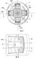
- each ceiling mounted notification device 15 includes a base 20 having a perimeter 201, a cover 21 which has a forward curvature but otherwise maintains a relatively low profile, a printed circuit board (PCB) 22 and an inner cover 23.
- PCB printed circuit board
- PCB printed circuit board
- circuitry generated using 3D printing techniques a solderless circuit board, a circuitry cube or circuitry that is integrated into base 20, cover 21, or inner cover 23 by various conventional and 3D printing techniques could all be used.
- features, such as circuitry 40, disposed on and/or connected to the PCB 22 in the following description may be connectably disposed on base 20, cover 21 or inner cover 23, or disposed on an additional structure in place of a PCB.
- the base 20 may be attachable to a ceiling or wall or some other similar surface in any of the rooms 13 and hallways 14 of the building 10.
- the cover 21 is attachable to and about the perimeter 201 of the base 20 to define an interior 24 and the PCB 22 may be operably disposed in the interior 24.
- the inner cover 23 protectively covers various features, including the PCB 22, in the interior 24. Note that where PCB 22 is integrated into base 20, cover 21 or inner cover 23, interior 24 may be condensed.
- Each ceiling mounted notification device 15 further includes four light sources 30, circuitry 40 that is operably disposed in the interior 24 and supportively disposed on and/or connected to the PCB 22 to activate and deactivate the four light sources 30 (and to effectively engage the four lenses 50).
- each ceiling mounted notification device 15 may also include an audio signal emission element 60 operably disposed in a central region 241 of the interior 24.
- the audio signal emission element 60 may be provided as a speaker or piezo-electric sounder that is capable of outputting an audible notification corresponding to the visible notification output by the four light sources 30.
- the audio signal emission element 60 would be activated and deactivated by the circuitry 40 and is operably disposed in the central region 241 of the interior 24 between the four light sources 30.
- the cover 21 has multiple portions. Among these are first portions 211 and a central portion 212.
- the first portions 211 are respectively disposed proximate to corresponding ones of the four light sources 30 and the four lenses 50.
- the first portions 211 may be transparent to permit light output from the four light sources 30 and the four lenses 50 to pass through.
- the central portion 212 is disposed proximate to the central region 241 of the interior 24 and, where applicable, the audio signal emission element 60.
- the central portion 212 may be perforated to allow audio signals to pass through.
- the remaining portions of the cover 21 may be provided as generally opaque and rigid portions that are supportive of the first portions 211 and the central portion 212.
- all portions of the cover 21 may be rigid and supportive, with portions 211 transparent, and remaining portions of the cover 21 opaque.
- the central portion 212 may be perforated, all and all remaining portions of the cover 21 may be rigid and supportive, with portions 211 transparent, and remaining portions of the cover 21 opaque.
- the four light sources 30 are arrayed within the interior 24 and around the perimeter 201 of the base 20 at ninety degree intervals from each other.
- the four light sources 30 may be substantially coplanar with each other.
- the four lenses 50 are arrayed in respective positional association with the four light sources 30 and may be substantially coplanar with each other.
- the four lenses 50 are located respectively proximate to corresponding ones of the four light sources 30 and are thus disposed at ninety degree intervals from one another.
- the four light sources 30 and the four lenses 50 cooperatively define a first light source and lens combination 3050 1 on an X-axis, a second light source and lens combination 3050 2 on a Y-axis, a third light source and lens combination 3050 3 on the X-axis and a fourth light source and lens combination 3050 4 on the Y-axis (see FIG. 4 ).
- the four light sources 30 may each be provided as a light emitting diode (LED) 31 although it is to be understood that any type of light source could be used to the extent that its power requirement does not unduly drain power from the power supply system 12.
- the four lenses 50 may each include a convex lens element 51, a concave lens element 52 and a total internal reflector (TIR) element 53 where such convexity or concavity is relative to a circumferential dimension defined about the central portion 212.
- TIR total internal reflector
- the convex lens element 51 would be centered at a corresponding one of the four light sources 30 and could be transparent or reflective whereas the concave lens element 52 and the TIR element 53 would be centered at the convex lens element 51 and could be substantially reflective of any light emitted by the corresponding one of the four light sources 30 and reflected thereon by the convex lens element 51.
- the components of the four lenses 50 may have a curvature that generally follows the profile shape of the cover 21 with increasing distance from the central portion 212. That is, with increasing distance from the central portion 212, the convex lens element 51 and the concave lens element 52 may curve or bend toward a plane of the base 20.
- the first light source and lens combination 3050 1 is separated from the second light source and lens combination 3050 2 and the fourth light source and lens combination 3050 4 by ninety degree intervals and is separated from the third light source and lens combination 3050 3 by a one hundred and eighty degree interval.
- the second light source and lens combination 3050 2 is separated from the first light source and lens combination 3050 1 and the third light source and lens combination 3050 3 by ninety degree intervals and is separated from the fourth light source and lens combination 3050 4 by a one hundred and eighty degree interval.
- the third light source and lens combination 3050 3 is separated from the second light source and lens combination 3050 2 and the fourth light source and lens combination 3050 4 by ninety degree intervals and is separated from the first light source and lens combination 3050 1 by a one hundred and eighty degree interval.
- the fourth light source and lens combination 3050 4 is separated from the first light source and lens combination 3050 1 and the third light source and lens combination 3050 3 by ninety degree intervals and is separated from the second light source and lens combination 3050 2 by a one hundred and eighty degree interval.
- the first-fourth light source and lens combinations 3050 1-4 when the four light sources 30 are activated by the circuitry 40, the first-fourth light source and lens combinations 3050 1-4 generate at least a UL 1971 compliant polar light pattern. More generally, when the four light sources 30 are activated by the circuitry 40, those light source and lens combinations that are one hundred and eighty degrees apart generate overlapping light output patterns and the other light source and lens combinations generate offset light output patterns.
- first and third light source and lens combinations 3050 1,3 which are substantially coaxial with one another along an X-axis, cooperatively output visible light in a first or X-Z plane and the second and fourth light source and lens combinations 3050 2,4 , which are substantially coaxial with one another along a Y-axis, cooperatively output visible light in a second or Y-Z plane that is orthogonal and, in some cases, perpendicular with the first or X-Z plane.
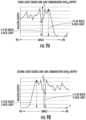
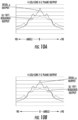
- the respective outputs of the first-fourth light source and lens combinations 3050 1-4 are graphically depicted and illustrate the contribution provided by each one of the first-fourth light source and lens combinations 3050 1-4 .
- the first light source and lens combination 3050 1 provides about 1 ⁇ 4 of the overall UL 1971 requirement for light output at and around the zero angle position (i.e., the center of the ceiling mounted notification device 15) and about 1 ⁇ 2 of the UL 1971 requirement for light output along the X-axis offset from the zero angle position.
- the zero angle position i.e., the center of the ceiling mounted notification device 15
- the second light source and lens combination 3050 2 provides about 1 ⁇ 4 of the overall UL 1971 requirement for light output at and around the zero angle position and about 1 ⁇ 2 of the UL 1971 requirement for light output along the Y-axis offset from the zero angle position.
- the third light source and lens combination 3050 3 provides about 1 ⁇ 4 of the overall UL 1971 requirement for light output at and around the zero angle position (i.e., the center of the ceiling mounted notification device 15) and about 1 ⁇ 2 of the UL 1971 requirement for light output along the X-axis offset from the zero angle position.
- the zero angle position i.e., the center of the ceiling mounted notification device 15
- the fourth light source and lens combination 3050 4 provides about 1 ⁇ 4 of the overall UL 1971 requirement for light output at and around the zero angle position and about 1 ⁇ 2 of the UL 1971 requirement for light output along the Y-axis offset from the zero angle position.
- the respective outputs of the UL 1971 requirement and of the combination of the first-fourth light source and lens combinations 3050 1-4 may be expressed as a percentage of the rated output at the zero angle position and surrounding positions as follows:
- the percentages may be higher or lower, nevertheless, the respective outputs of the combination of the first-fourth light source and lens combinations 3050 1-4 are the same or greater than
- each of the ceiling mounted notification device 15 is not limited to any shape in particular and can in fact vary from one to another, the embodiments of FIGS. 3-7 generally relate to ceiling mounted notification devices 15 that are annular or circular in shape. This is done for clarity and brevity and it is to be understood that other shapes are possible.
- the ceiling mounted notification devices 15 may have polygonal shapes in some cases. Regardless, the ceiling mounted notification devices 15 are UL 1971 compliant.
- the ceiling mounted notification devices 15 described herein will reduce overall current consumption as compared to currently available devices and allow for more devices to be powered from a same power supply system 12 while reducing overall system costs. Specifically, the described ceiling mounted notification devices 15 allow for ultra-low current draw while providing illumination throughout a defined area; resulting in a higher light candela with a shorter flash duration than conventional LED strobe configurations. For example, the input current required for an LED meeting the latest UL and NFPA requirements for maximum flash duration of 20 milliseconds may be reduced significantly below those of both Xenon and conventional LED strobes. In other words, less energy is required per flash.
- significantly reduced current levels are beneficial at least because more devices can be powered from any given supply, thus reducing the number of supplies needed for large systems; and/or reduced wire size; and/or longer cable runs. These benefits can reduce the overall cost of installation.
- the design of the ceiling mounted notification devices 15 also frees up central parts thereof for a speaker or sounder and allows for a relatively lower device profile.
Landscapes
- Engineering & Computer Science (AREA)
- Physics & Mathematics (AREA)
- General Engineering & Computer Science (AREA)
- General Physics & Mathematics (AREA)
- Electromagnetism (AREA)
- Microelectronics & Electronic Packaging (AREA)
- Optics & Photonics (AREA)
- Computer Security & Cryptography (AREA)
- Environmental & Geological Engineering (AREA)
- Chemical & Material Sciences (AREA)
- Analytical Chemistry (AREA)
- Business, Economics & Management (AREA)
- Emergency Management (AREA)
- Non-Portable Lighting Devices Or Systems Thereof (AREA)
- Arrangement Of Elements, Cooling, Sealing, Or The Like Of Lighting Devices (AREA)
- Finishing Walls (AREA)
Applications Claiming Priority (3)
| Application Number | Priority Date | Filing Date | Title |
|---|---|---|---|
| US201762485232P | 2017-04-13 | 2017-04-13 | |
| PCT/US2018/026888 WO2018191264A1 (en) | 2017-04-13 | 2018-04-10 | Notification device for a surface of a building interior |
| EP18722288.0A EP3610195B1 (de) | 2017-04-13 | 2018-04-10 | Benachrichtigungsvorrichtung für eine oberfläche eines gebäudeinnenraums |
Related Parent Applications (2)
| Application Number | Title | Priority Date | Filing Date |
|---|---|---|---|
| EP18722288.0A Division-Into EP3610195B1 (de) | 2017-04-13 | 2018-04-10 | Benachrichtigungsvorrichtung für eine oberfläche eines gebäudeinnenraums |
| EP18722288.0A Division EP3610195B1 (de) | 2017-04-13 | 2018-04-10 | Benachrichtigungsvorrichtung für eine oberfläche eines gebäudeinnenraums |
Publications (2)
| Publication Number | Publication Date |
|---|---|
| EP4407577A2 true EP4407577A2 (de) | 2024-07-31 |
| EP4407577A3 EP4407577A3 (de) | 2024-10-09 |
Family
ID=62111196
Family Applications (2)
| Application Number | Title | Priority Date | Filing Date |
|---|---|---|---|
| EP24182406.9A Pending EP4407577A3 (de) | 2017-04-13 | 2018-04-10 | Benachrichtigungsvorrichtung für eine oberfläche eines gebäudeinnenraums |
| EP18722288.0A Active EP3610195B1 (de) | 2017-04-13 | 2018-04-10 | Benachrichtigungsvorrichtung für eine oberfläche eines gebäudeinnenraums |
Family Applications After (1)
| Application Number | Title | Priority Date | Filing Date |
|---|---|---|---|
| EP18722288.0A Active EP3610195B1 (de) | 2017-04-13 | 2018-04-10 | Benachrichtigungsvorrichtung für eine oberfläche eines gebäudeinnenraums |
Country Status (4)
| Country | Link |
|---|---|
| US (1) | US10989368B2 (de) |
| EP (2) | EP4407577A3 (de) |
| ES (1) | ES2984903T3 (de) |
| WO (1) | WO2018191264A1 (de) |
Families Citing this family (5)
| Publication number | Priority date | Publication date | Assignee | Title |
|---|---|---|---|---|
| USD880324S1 (en) * | 2017-11-30 | 2020-04-07 | Carrier Corporation | Notification appliance |
| CN111161491A (zh) * | 2018-11-08 | 2020-05-15 | 江门市奇斌模具制品有限公司 | 声光一体化消防警报器 |
| USD960741S1 (en) * | 2020-07-17 | 2022-08-16 | Carrier Corporation | Notification appliance |
| USD982465S1 (en) | 2020-07-17 | 2023-04-04 | Carrier Corporation | Notification appliance |
| US12163654B2 (en) * | 2022-08-23 | 2024-12-10 | Eaton Intelligent Power Limited | Audio and visual notification appliance |
Family Cites Families (27)
| Publication number | Priority date | Publication date | Assignee | Title |
|---|---|---|---|---|
| EP1103937B1 (de) | 1999-11-19 | 2005-05-11 | Siemens Building Technologies AG | Brandmelder |
| US6739738B1 (en) | 2003-01-28 | 2004-05-25 | Whelen Engineering Company, Inc. | Method and apparatus for light redistribution by internal reflection |
| US7636049B2 (en) | 2005-12-14 | 2009-12-22 | Ellul Jr Joseph | Emergency notification and directional signaling apparatus |
| EP2093731A1 (de) | 2008-02-19 | 2009-08-26 | Siemens Aktiengesellschaft | Linearer optischer Rauchmelder mit mehreren Teilstrahlen |
| US7976187B2 (en) | 2008-03-27 | 2011-07-12 | Cree, Inc. | Uniform intensity LED lighting system |
| WO2009139065A1 (ja) * | 2008-05-16 | 2009-11-19 | Necディスプレイソリューションズ株式会社 | 冷却ポンプユニットおよびそれを備える投写型表示装置 |
| US8653984B2 (en) | 2008-10-24 | 2014-02-18 | Ilumisys, Inc. | Integration of LED lighting control with emergency notification systems |
| US8220948B2 (en) | 2009-09-14 | 2012-07-17 | Cooper Technologies Company | Optically efficient notification device for use in life safety ceiling strobe applications |
| US8113694B2 (en) * | 2009-09-14 | 2012-02-14 | Cooper Technologies Company | Optically efficient notification device for use in life safety wall strobe applications |
| JP2014075176A (ja) | 2010-09-16 | 2014-04-24 | Brintz Technologie Co Ltd | Led照明装置 |
| CN101963316B (zh) | 2010-10-28 | 2012-07-18 | 鸿富锦精密工业(深圳)有限公司 | Led吊顶灯 |
| FR2970102B1 (fr) | 2010-12-31 | 2012-12-28 | Jacques Lewiner | Detecteur de fumee |
| CN102129755B (zh) | 2011-01-06 | 2012-07-04 | 中国科学技术大学 | 一种基于前向小角度散射的光电感烟探测器 |
| FR2975809A1 (fr) * | 2011-05-23 | 2012-11-30 | Selvarasa Nageswaran | Detecteur de fumees et gaz toxiques avec eclairage amoule a economie d' energie |
| DE102012214357A1 (de) | 2012-08-13 | 2014-02-13 | Robert Bosch Gmbh | Brandmeldevorrichtung |
| EP2706515B1 (de) | 2012-09-07 | 2014-11-12 | Amrona AG | Vorrichtung und Verfahren zum Detektieren von Streulichtsignalen |
| GB2506138B (en) | 2012-09-20 | 2014-11-19 | Cooper Technologies Co | Lens and light emitting device incorporating a lens |
| CN103883888B (zh) * | 2012-12-19 | 2016-01-20 | 上海广茂达光艺科技股份有限公司 | 灯具及灯具模块 |
| US9316382B2 (en) * | 2013-01-31 | 2016-04-19 | Cree, Inc. | Connector devices, systems, and related methods for connecting light emitting diode (LED) modules |
| EP3270041B1 (de) | 2013-04-19 | 2019-07-10 | Quarkstar LLC | Beleuchtungsvorrichtungen mit einstellbaren optischen elementen |
| US9251675B2 (en) * | 2013-10-23 | 2016-02-02 | Honeywell International Inc. | Multiple LED omni-directional visual alarm device |
| EP2908298B1 (de) | 2014-02-13 | 2018-04-18 | Siemens Schweiz AG | Rauchmelder nach dem Streulichtprinzip mit einer zweifarbigen Leuchtdiode mit unterschiedlich grossen LED-Chips |
| US9574763B2 (en) | 2014-03-12 | 2017-02-21 | Kaipo Chen | Multifunctional home monitoring system combined with lighting device |
| ES2721929T3 (es) | 2014-12-01 | 2019-08-06 | Siemens Schweiz Ag | Detector de humo de luz dispersa con un diodo emisor de luz de dos colores |
| EP3029647B1 (de) | 2014-12-04 | 2017-05-31 | Siemens Schweiz AG | Offener Streulichtrauchmelder, insbesondere mit einer Sidelooker-LED |
| EP3131077B1 (de) | 2015-08-13 | 2017-10-18 | Siemens Schweiz AG | Optische rauchdetektionseinheit für einen rauchmelder mit zwei miteinander optisch gekoppelten leuchtdioden und mit einer damit verbundenen steuereinheit zur ableitung einer alterungsinformation sowie rauchmelder |
| WO2017081663A1 (en) * | 2015-11-13 | 2017-05-18 | Huizhou Light Engine Limited | Light emitting diode strobe lighting system |
-
2018
- 2018-04-10 EP EP24182406.9A patent/EP4407577A3/de active Pending
- 2018-04-10 US US16/500,760 patent/US10989368B2/en active Active
- 2018-04-10 ES ES18722288T patent/ES2984903T3/es active Active
- 2018-04-10 WO PCT/US2018/026888 patent/WO2018191264A1/en not_active Ceased
- 2018-04-10 EP EP18722288.0A patent/EP3610195B1/de active Active
Also Published As
| Publication number | Publication date |
|---|---|
| EP3610195B1 (de) | 2024-08-14 |
| ES2984903T3 (es) | 2024-10-31 |
| WO2018191264A1 (en) | 2018-10-18 |
| US20200124239A1 (en) | 2020-04-23 |
| US10989368B2 (en) | 2021-04-27 |
| EP3610195A1 (de) | 2020-02-19 |
| EP4407577A3 (de) | 2024-10-09 |
Similar Documents
| Publication | Publication Date | Title |
|---|---|---|
| EP3610195B1 (de) | Benachrichtigungsvorrichtung für eine oberfläche eines gebäudeinnenraums | |
| EP2278214A1 (de) | Lichtemittierende Vorrichtung | |
| US9755448B2 (en) | LED luminaire with integrated battery backup | |
| US10145531B2 (en) | Light emitting diode strobe lighting system | |
| US8465170B2 (en) | Optically efficient notification device for use in life safety ceiling strobe applications | |
| US8939615B2 (en) | Optically efficient notification device for use in life safety wall strobe applications | |
| US11754773B2 (en) | Curved edge-lit light guide | |
| JP2016103373A (ja) | 照明器具 | |
| US10274150B2 (en) | LED luminaire with integrated battery backup | |
| JP2015057791A (ja) | 照明装置 | |
| JP2012079500A (ja) | 照明装置 | |
| US11585526B2 (en) | Lighting apparatus | |
| JP7448215B2 (ja) | Led照明器具 | |
| JP7448216B2 (ja) | Led照明器具 | |
| KR101122162B1 (ko) | 엘이디 조명장치 | |
| KR100894324B1 (ko) | 조명 겸용 실링스피커 | |
| JP2017059514A (ja) | カラーled薄型導光板パネル式警告灯 | |
| JP2018125315A (ja) | 照明器具 | |
| JP2017224423A (ja) | Led照明器具 | |
| US20140293599A1 (en) | Air cooling led lamp | |
| JP2017224424A (ja) | Led照明器具 | |
| JP2016207370A (ja) | Led照明装置 | |
| JP2018092843A (ja) | 照明器具 | |
| JP2018116915A (ja) | 照明装置 | |
| BG2324U1 (bg) | Многофункционааен модулен блок |
Legal Events
| Date | Code | Title | Description |
|---|---|---|---|
| PUAI | Public reference made under article 153(3) epc to a published international application that has entered the european phase |
Free format text: ORIGINAL CODE: 0009012 |
|
| STAA | Information on the status of an ep patent application or granted ep patent |
Free format text: STATUS: THE APPLICATION HAS BEEN PUBLISHED |
|
| AC | Divisional application: reference to earlier application |
Ref document number: 3610195 Country of ref document: EP Kind code of ref document: P |
|
| AK | Designated contracting states |
Kind code of ref document: A2 Designated state(s): AL AT BE BG CH CY CZ DE DK EE ES FI FR GB GR HR HU IE IS IT LI LT LU LV MC MK MT NL NO PL PT RO RS SE SI SK SM TR |
|
| REG | Reference to a national code |
Ref country code: DE Ref legal event code: R079 Free format text: PREVIOUS MAIN CLASS: G08B0005360000 Ipc: F21V0033000000 |
|
| PUAL | Search report despatched |
Free format text: ORIGINAL CODE: 0009013 |
|
| AK | Designated contracting states |
Kind code of ref document: A3 Designated state(s): AL AT BE BG CH CY CZ DE DK EE ES FI FR GB GR HR HU IE IS IT LI LT LU LV MC MK MT NL NO PL PT RO RS SE SI SK SM TR |
|
| RIC1 | Information provided on ipc code assigned before grant |
Ipc: F21V 5/08 20060101ALI20240905BHEP Ipc: F21V 5/04 20060101ALI20240905BHEP Ipc: G08B 5/36 20060101ALI20240905BHEP Ipc: G08B 17/103 20060101ALI20240905BHEP Ipc: G08B 5/38 20060101ALI20240905BHEP Ipc: F21S 9/02 20060101ALI20240905BHEP Ipc: F21V 33/00 20060101AFI20240905BHEP |
|
| STAA | Information on the status of an ep patent application or granted ep patent |
Free format text: STATUS: REQUEST FOR EXAMINATION WAS MADE |
|
| 17P | Request for examination filed |
Effective date: 20250407 |