EP4407364A1 - Vorrichtung und verfahren zur einstellung des abstandes zwischen linsenzylindern, vorrichtung und computermedium - Google Patents
Vorrichtung und verfahren zur einstellung des abstandes zwischen linsenzylindern, vorrichtung und computermedium Download PDFInfo
- Publication number
- EP4407364A1 EP4407364A1 EP23745900.3A EP23745900A EP4407364A1 EP 4407364 A1 EP4407364 A1 EP 4407364A1 EP 23745900 A EP23745900 A EP 23745900A EP 4407364 A1 EP4407364 A1 EP 4407364A1
- Authority
- EP
- European Patent Office
- Prior art keywords
- distance
- adjustment circuit
- right lens
- control instruction
- output voltage
- Prior art date
- Legal status (The legal status is an assumption and is not a legal conclusion. Google has not performed a legal analysis and makes no representation as to the accuracy of the status listed.)
- Pending
Links
- 238000000034 method Methods 0.000 title claims abstract description 61
- 230000001179 pupillary effect Effects 0.000 claims abstract description 54
- 230000004044 response Effects 0.000 claims abstract description 29
- 238000012545 processing Methods 0.000 claims description 67
- 238000004590 computer program Methods 0.000 claims description 27
- 230000006698 induction Effects 0.000 claims description 24
- 238000010586 diagram Methods 0.000 description 8
- 230000006870 function Effects 0.000 description 5
- 230000001360 synchronised effect Effects 0.000 description 5
- 238000005516 engineering process Methods 0.000 description 4
- 230000008878 coupling Effects 0.000 description 3
- 238000010168 coupling process Methods 0.000 description 3
- 238000005859 coupling reaction Methods 0.000 description 3
- 238000004891 communication Methods 0.000 description 2
- 238000004088 simulation Methods 0.000 description 2
- 230000003068 static effect Effects 0.000 description 2
- 230000005856 abnormality Effects 0.000 description 1
- 230000006399 behavior Effects 0.000 description 1
- 238000006243 chemical reaction Methods 0.000 description 1
- 238000013500 data storage Methods 0.000 description 1
- 238000013461 design Methods 0.000 description 1
- 238000011161 development Methods 0.000 description 1
- 230000009189 diving Effects 0.000 description 1
- 230000001815 facial effect Effects 0.000 description 1
- 230000004927 fusion Effects 0.000 description 1
- 230000002452 interceptive effect Effects 0.000 description 1
- 230000003287 optical effect Effects 0.000 description 1
- 239000013307 optical fiber Substances 0.000 description 1
- 239000004065 semiconductor Substances 0.000 description 1
- 239000007787 solid Substances 0.000 description 1
- 238000006467 substitution reaction Methods 0.000 description 1
- 230000000007 visual effect Effects 0.000 description 1
- 239000002699 waste material Substances 0.000 description 1
Images

Classifications
-
- G—PHYSICS
- G02—OPTICS
- G02B—OPTICAL ELEMENTS, SYSTEMS OR APPARATUS
- G02B27/00—Optical systems or apparatus not provided for by any of the groups G02B1/00 - G02B26/00, G02B30/00
- G02B27/01—Head-up displays
-
- G—PHYSICS
- G02—OPTICS
- G02B—OPTICAL ELEMENTS, SYSTEMS OR APPARATUS
- G02B27/00—Optical systems or apparatus not provided for by any of the groups G02B1/00 - G02B26/00, G02B30/00
-
- G—PHYSICS
- G02—OPTICS
- G02B—OPTICAL ELEMENTS, SYSTEMS OR APPARATUS
- G02B27/00—Optical systems or apparatus not provided for by any of the groups G02B1/00 - G02B26/00, G02B30/00
- G02B27/0093—Optical systems or apparatus not provided for by any of the groups G02B1/00 - G02B26/00, G02B30/00 with means for monitoring data relating to the user, e.g. head-tracking, eye-tracking
-
- G—PHYSICS
- G02—OPTICS
- G02B—OPTICAL ELEMENTS, SYSTEMS OR APPARATUS
- G02B27/00—Optical systems or apparatus not provided for by any of the groups G02B1/00 - G02B26/00, G02B30/00
- G02B27/01—Head-up displays
- G02B27/017—Head mounted
- G02B27/0172—Head mounted characterised by optical features
-
- G—PHYSICS
- G02—OPTICS
- G02B—OPTICAL ELEMENTS, SYSTEMS OR APPARATUS
- G02B27/00—Optical systems or apparatus not provided for by any of the groups G02B1/00 - G02B26/00, G02B30/00
- G02B27/01—Head-up displays
- G02B27/017—Head mounted
- G02B27/0176—Head mounted characterised by mechanical features
-
- G—PHYSICS
- G02—OPTICS
- G02B—OPTICAL ELEMENTS, SYSTEMS OR APPARATUS
- G02B7/00—Mountings, adjusting means, or light-tight connections, for optical elements
- G02B7/02—Mountings, adjusting means, or light-tight connections, for optical elements for lenses
- G02B7/12—Adjusting pupillary distance of binocular pairs
-
- G—PHYSICS
- G02—OPTICS
- G02B—OPTICAL ELEMENTS, SYSTEMS OR APPARATUS
- G02B27/00—Optical systems or apparatus not provided for by any of the groups G02B1/00 - G02B26/00, G02B30/00
- G02B27/01—Head-up displays
- G02B27/0101—Head-up displays characterised by optical features
- G02B2027/0132—Head-up displays characterised by optical features comprising binocular systems
-
- G—PHYSICS
- G02—OPTICS
- G02B—OPTICAL ELEMENTS, SYSTEMS OR APPARATUS
- G02B27/00—Optical systems or apparatus not provided for by any of the groups G02B1/00 - G02B26/00, G02B30/00
- G02B27/01—Head-up displays
- G02B27/0101—Head-up displays characterised by optical features
- G02B2027/0138—Head-up displays characterised by optical features comprising image capture systems, e.g. camera
-
- G—PHYSICS
- G02—OPTICS
- G02B—OPTICAL ELEMENTS, SYSTEMS OR APPARATUS
- G02B27/00—Optical systems or apparatus not provided for by any of the groups G02B1/00 - G02B26/00, G02B30/00
- G02B27/01—Head-up displays
- G02B27/0149—Head-up displays characterised by mechanical features
- G02B2027/0154—Head-up displays characterised by mechanical features with movable elements
Definitions
- the present disclosure relates to the technical field of virtual reality, and in particular relates to a method, apparatus for lens barrel distance adjustment, device and computer medium.
- a Virtual Reality (VR) device is a device that can create and for users to experience a virtual world. It can generate a simulation environment based on a computer program and provide a multi-source information fusion, interactive three-dimensional dynamic vision and entity behavior simulation that immerses users in a virtual environment.
- Embodiments of the present disclosure provide an implementation solution that is different from the related art to solve the technical problem in the related art that the adjustment efficiency of the distance adjustment manner between the left and right lens barrels of the head-mounted device is low.
- embodiments of the present disclosure provide an apparatus for lens barrel distance adjustment that comprises a data processing circuit, an adjustment circuit, and a hall sensor, wherein:
- the hall sensor is configured to sense a magnetic induction intensity of a magnet related to a distance between left and right lens barrels of a head-mounted device, and output a corresponding first output voltage based on the magnetic induction intensity.
- the data processing circuit is connected to the hall sensor and the adjustment circuit and configured to obtain the first output voltage; in response to that the first output voltage indicates that an absolute value of a difference value between a distance between the left and right lens barrels and a pupillary distance of a user is greater than a predetermined threshold, send a control instruction corresponding to the difference value to the adjustment circuit, causing the adjustment circuit to adjust a distance between the left and right lens barrels based on the control instruction.
- the adjustment circuit is configured to receive the control instruction and adjust a distance between the left and right lens barrels based on the control instruction.
- embodiments of the present disclosure provide a method for adjusting a lens barrel distance that comprises:
- embodiments of the present disclosure provide a head-mounted device that comprises a camera group, a data processing circuit, an adjustment circuit, and a hall sensor, wherein:
- the camera group is configured to take an eye image of a user.
- the hall sensor is configured to sense a magnetic induction intensity of a magnet related to a distance between left and right lens barrels of a head-mounted device, and output a corresponding first output voltage based on the magnetic induction intensity.
- the data processing circuit is connected to the hall sensor and the adjustment circuit and configured to obtain the first output voltage; in response to that the first output voltage indicates that an absolute value of a difference value between a distance between the left and right lens barrels and a pupillary distance of a user is greater than a predetermined threshold, send a control instruction corresponding to the difference value to the adjustment circuit, causing the adjustment circuit to adjust a distance between the left and right lens barrels based on the control instruction.
- the adjustment circuit is configured to receive the control instruction and adjust a distance between the left and right lens barrels based on the control instruction.
- embodiments of the present disclosure provide an apparatus for lens barrel distance adjustment that comprises:
- embodiments of the present disclosure provide an electronic device that comprises:
- embodiments of the present disclosure provide a computer-readable storage medium on which a computer program is stored, the computer program, when executed by a processor, implementing any method in the second aspect or the possible implementation manner of the second aspect.
- embodiments of the present disclosure provide a computer program product that comprises a computer program, when executed by a processor, implementing any method in the second aspect or the possible implementation manner of the second aspect.
- the present disclosure provides an apparatus for lens barrel distance adjustment, which specifically comprises: a data processing circuit, an adjustment circuit, and a hall sensor, wherein: the hall sensor is configured to sense a magnetic induction intensity of a magnet related to a distance between left and right lens barrels of a head-mounted device, and output a corresponding first output voltage based on the magnetic induction intensity; the data processing circuit is connected to the hall sensor and the adjustment circuit and configured to obtain the first output voltage; in response to that the first output voltage indicates that an absolute value of a difference value between a distance between the left and right lens barrels and a pupillary distance of a user is greater than a predetermined threshold, send a control instruction corresponding to the difference value to the adjustment circuit, causing the adjustment circuit to adjust a distance between the left and right lens barrels based on the control instruction; the adjustment circuit is configured to receive the control instruction and adjust a distance between the left and right lens barrels based on the control instruction.
- the distance between the left and right lens barrels can be
- Figure 1a is a schematic structural diagram of an apparatus for lens barrel distance adjustment provided according to an embodiment of the present disclosure.
- the circuit can be applied to a head-mounted device.
- the circuit can includes: a data processing circuit 11, an adjustment circuit 12, and a hall sensor 13, wherein:
- the Hall sensor 13 is configured to sense a magnetic induction intensity of a magnet related to a distance between left and right lens barrels of a head-mounted device, and output a corresponding first output voltage based on the magnetic induction intensity.
- the data processing circuit 11 is connected to the hall sensor and the adjustment circuit and configured to obtain the first output voltage; in response to that the first output voltage indicates that an absolute value of a difference value between a distance between the left and right lens barrels and a pupillary distance of a user is greater than a predetermined threshold, send a control instruction corresponding to the difference value to the adjustment circuit, causing the adjustment circuit to adjust a distance between the left and right lens barrels based on the control instruction;
- the adjustment circuit 12 is configured to receive the control instruction and adjust a distance between the left and right lens barrels based on the control instruction.
- the hall sensor 13 is configured to sense a magnetic induction intensity of a magnet related to a distance between left and right lens barrels of a head-mounted device, and output a corresponding first output voltage based on the magnetic induction intensity.
- the magnet can be arranged at a predetermined position.
- the predetermined position can be on the lens barrel bracket.
- it can be arranged on the left lens barrel bracket or the right lens barrel bracket.
- the magnet may move along with adjustment of the position of the left and right lens barrels.
- the hall sensor 13 is fixedly arranged, that is, the position of the hall sensor 13 is fixed and does not move along with the movement of the left and right lens barrels.
- the hall sensor 13 can be a hall linear sensor, when the magnet moves to different positions, the magnetic induction intensity of the magnet sensed by the hall sensor 13 is different, so that the corresponding first output voltage can be output according to the magnetic induction intensity.
- the distance between the left and right lens barrels described in this disclosure refers to the distance between the center of the left lens barrel and the center of the right lens barrel.
- the storage unit in the data processing circuit 11 may store a corresponding relationship between different first output voltages and the corresponding distances between the left and right lens barrels, and the data processing circuit 11 may determine the distance between the left and right lens barrels corresponding to the currently received first output voltage based on the corresponding relationship, and compare the distance with the pupillary distance of the user.
- the first output voltage indicates that an absolute value of a difference value between a distance between the left and right lens barrels and a pupillary distance of a user is greater than a predetermined threshold
- the distance between the left and right lens barrels needs to be adjusted, so that the distance is the same as the pupillary distance of the user, or the difference is not greater than the predetermined threshold.
- the pupillary distance of the user can be determined by the data processing circuit 11 based on the eye image of the user received from the camera group.
- the camera group includes a plurality of cameras, and the plurality of cameras can be disposed on an inner side of the head-mounted device, and an inner side of the head-mounted device indicates a side of the user behind the head-mounted device that faces the user.
- the eye image may be directly received from the camera group that captures an image of the user's eye area, or may be obtained by cropping the user's facial image captured by the camera group, to which the disclosure is not limited.
- the adjustment circuit 12 when the adjustment circuit 12 is configured to adjust the distance between the left and right lens barrels based on the control instruction, the adjustment circuit 12 is specifically configured to drive the left lens barrel and/or the right lens barrel to move based on the control instruction.
- the adjustment circuit 12 can only drive any one of the left lens barrels and the right lens barrel to move to adjust the distance between the left and right lens barrels or can simultaneously drive the left lens barrel and the lens barrel to move to adjust the distance between the left and right lens barrels.
- the adjustment circuit 12 includes a drive circuit 121 and a stepper motor 122; wherein:
- the driving circuit 121 is connected to the data processing circuit 11 and the stepper motor 122, and configured to receive the control instruction and generate a corresponding driving signal based on the control instruction.
- the stepper motor 122 is configured to drive the left lens barrel and/or the right lens barrel to move based on the driving signal.
- the data processing circuit 11 includes: a first processing circuit 111 and a second processing circuit 112, wherein:
- the first processing circuit 111 is connected to a camera group and the second processing circuit and configured to obtain an eye image of user from the camera group and determine a pupillary distance of a user based on the eye image.
- the second processing circuit 112 is connected to the hall sensor and the adjustment circuit and configured to obtain the first output voltage; in response to that the first output voltage indicates that an absolute value of a difference value between a distance between the left and right lens barrels and a pupillary distance of a user is greater than a predetermined threshold, send a control instruction corresponding to the difference value to the adjustment circuit, causing the adjustment circuit to adjust a distance between the left and right lens barrels based on the control instruction.
- the first processing circuit may be a virtual and extended reality processor
- the second processing circuit may be an MCU (Microcontroller Unit).
- the lens barrel distance adjustment device further includes: a limiting circuit 14.
- the limiting circuit 14 is connected to the data processing circuit 11 and the left lens barrel and/or the right lens barrel and configured to generate a corresponding limit prompt signal when the left lens barrel and/or the right lens barrel move to a corresponding limit position.
- the data processing circuit 11 is further configured to stop sending control instruction to the adjustment circuit 12 when the limit prompt signal is detected.
- the adjustment distance corresponding to the stopped control instruction is smaller than the adjustment distance corresponding to the control instruction sent before the limit prompt signal is detected.
- the limit prompt signal is a prompt voltage generated when the limiting circuit 14 detects that the left lens barrel or the right lens barrel moves to the corresponding limit position.
- the limiting circuit 14 can be connected to its corresponding limit position to determine whether the left lens barrel or the right lens barrel moves to the corresponding limit position according to the switching condition of the limit position.
- the data processing circuit 11 is further configured to:
- the adjustment circuit 12 After sending the control instruction corresponding to the difference value to the adjustment circuit 12, obtain a second output voltage output by the hall sensor 13; in response to that the second output voltage indicates that an absolute value of a difference value between a distance between the left and right lens barrels and a pupillary distance of a user is not greater than the predetermined threshold, stop sending an instruction to the adjustment circuit 12 that indicates the adjustment circuit 12 to adjust a distance between the left and right lens barrels.
- the instruction may also be an instruction sent by the data processing circuit 11 after sending the control instruction.
- the second output voltage is the voltage output by the hall sensor after outputting the first output voltage.
- the hall sensor can output a voltage to the data processing circuit 11 according to a certain output cycle.
- the camera group in the present disclosure may be an infrared camera group, including a plurality of infrared cameras, and each infrared camera may be configured with an infrared lamp.
- the apparatus for lens barrel distance adjustment in the present disclosure can be applied to a head-mounted all-in-one machine.
- the present disclosure can determine whether the left lens barrel or the right lens barrel reaches the corresponding limit position through the limiting circuit, or determine whether the left lens barrel or the right lens barrel reaches the corresponding limit position through the output voltage of the hall sensor according to the user requirements, which is not limited in the present disclosure.
- the left lens barrel can independently correspond to a magnet and a hall sensor
- the right lens barrel can correspond to another magnet and a hall sensor.
- the data processing circuit can determine the distance between the left and right lens barrels through the output voltage of any hall sensor.
- the data processing circuit can also determine the distance between the left and right lens barrels based on the average output voltage of the two hall sensors. The present disclosure does not limit this.
- the bracket of the left and right lens barrels are respectively provided with a magnet, and each magnet corresponds to a magnet with fixed position.
- the left lens barrel can independently correspond to a limiting circuit
- the right lens barrel can correspond to another limiting circuit.
- the data processing circuit can determine the respective movement progress of the left and right lens barrels by determining whether to detect limiting prompt signal of the limiting circuit corresponding to the distance between the left lens barrel and the right mirror is detected.
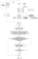
- FIG. 1c provides an example of an apparatus for lens barrel distance adjustment.
- the first processing circuit 111 can determine the inter pupillary distance of the user based on eye tracking technology, and transmit the pupillary distance of the user to the MCU (i.e., the second processing circuit), the MCU can connect to the hall sensor corresponding to the left lens barrel and the hall sensor corresponding to the right lens barrel through some of its interfaces (such as GPIO12 and GPIO13), and the MCU may determine the distance between the left and right lens barrels based on the voltage of the partial interface.
- the MCU i.e., the second processing circuit
- the MCU can connect to the hall sensor corresponding to the left lens barrel and the hall sensor corresponding to the right lens barrel through some of its interfaces (such as GPIO12 and GPIO13), and the MCU may determine the distance between the left and right lens barrels based on the voltage of the partial interface.
- the MCU may generate a corresponding control instruction according to the difference between the distance between the left and right lens barrels and the pupillary distance of the user, and the control instruction is transmitted to the motor driver (driving circuit) through another part of the interface (such as GPIO6, GPIO7, GPIO8, and GPIO9), so that the motor drives the left lens barrel and/or the right lens barrel to move through the stepper motor.
- the control instruction includes: an enable signal, a standby control signal, a direction signal for indicating the rotation direction of the stepper motor, and a pulse signal.
- the four signals can be transmitted to the motor drive through the EN interface, STBY interface, DIR interface, and STCK interface in the motor drive respectively.
- the operating voltage of the MCU can be 3.3V
- the motor driver can be boosted through another interface (GPIOS) to make the motor driver work normally.
- the MCU can perform analog-to-digital conversion on the received voltage to determine the final voltage.
- connection manner between the MCU and the first processing circuit can be seen as shown in Figure 1c , which will not be described again here.
- the data processing circuit in the present disclosure can obtain the pupillary distance of the user, obtain the output voltage of the Hall sensor, determine the distance between the centers of the left and right lens barrels based on the output voltage, and determine whether the difference between the distance between the distance between the centers of the left and right lens barrels and the pupillary distance of the user is greater than the predetermined threshold, and if yes, the drive circuit is controlled to drive the stepper motor to rotate to drive the left lens barrel and/or the right lens barrel to move, so that the difference between the distance between the center of the left and right lens barrels and the pupillary distance of the user is not greater than the predetermined threshold, and if no, the process ends.
- the drive circuit After the drive circuit is controlled to drive the stepper motor to rotate, it can also be determined whether the limiting signal is detected. If yes, the process ends. If not, the drive circuit is continued to be controlled to drive the stepper motor to rotate.
- the output voltage of the hall sensor in the process of controlling the drive circuit to drive the stepper standby rotation, can be continued to be obtained in real time, and the distance between the center of the left and right lens barrels is determined based on the output voltage, and when the difference between the distance between the canters of the left and right lens barrels and the pupillary distance of the user is not greater than the predetermined threshold based on the output voltage of the hall sensor, the control diving circuit is stopped to drive the stepping motor to rotate.
- the lens barrel distance adjustment device specifically includes: a data processing circuit, an adjustment circuit, and a hall sensor, wherein: the hall sensor is configured to sense a magnetic induction intensity of a magnet related to a distance between left and right lens barrels of a head-mounted device, and output a corresponding first output voltage based on the magnetic induction intensity; the data processing circuit is connected to the hall sensor and the adjustment circuit and configured to obtain the first output voltage; in response to that the first output voltage indicates that an absolute value of a difference value between a distance between the left and right lens barrels and a pupillary distance of a user is greater than a predetermined threshold, send a control instruction corresponding to the difference value to the adjustment circuit, causing the adjustment circuit to adjust a distance between the left and right lens barrels based on the control instruction; the adjustment circuit is configured to receive the control instruction and adjust a distance between the left and right lens barrels based on the control instruction.
- the apparatus for lens barrel distance adjustment of the present disclosure can automatically adjust the distance between the left and right lens barrel
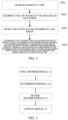
- Figure 2 is a schematic flowchart of a method for lens barrel distance adjustment provided according to an embodiment of the present disclosure.
- the method can be applied to a head-mounted device.
- the method at least includes the following steps:
- the method further includes:
- the method further includes: stopping sending an instruction to the adjustment circuit that indicates the adjustment circuit to adjust the distance between the left and right lens barrels when a limit prompt signal is detected.
- the present disclosure further provides a head-mounted device includes: a camera group, a data processing circuit, an adjustment circuit, and a hall sensor, wherein:
- the camera group is configured to take an eye image of a user.
- the hall sensor is configured to sense a magnetic induction intensity of a magnet related to a distance between left and right lens barrels of a head-mounted device, and output a corresponding first output voltage based on the magnetic induction intensity.
- the data processing circuit is connected to the hall sensor and the adjustment circuit and configured to obtain the first output voltage; in response to that the first output voltage indicates that an absolute value of a difference value between a distance between the left and right lens barrels and a pupillary distance of a user is greater than a predetermined threshold, send a control instruction corresponding to the difference value to the adjustment circuit, causing the adjustment circuit to adjust a distance between the left and right lens barrels based on the control instruction.
- the adjustment circuit is configured to receive the control instruction and adjust a distance between the left and right lens barrels based on the control instruction.
- Figure 3 is a schematic structural diagram of an apparatus for lens barrel distance adjustment provided according to an embodiment of the present disclosure.
- the apparatus for lens barrel distance adjustment can be applied to a head-mounted device includes:
- the apparatus is further configured to:
- the above device is further configured to: stop sending an instruction to the adjustment circuit that indicates the adjustment circuit to adjust the distance between the left and right lens barrels when a limit prompt signal is detected.
- apparatus embodiments and method embodiments may correspond to each other, and similar descriptions may refer to method embodiments. To avoid repetition, details are not described herein again.
- the apparatus can execute the above method embodiments, and the foregoing and other operations and/or functions of each module in the apparatus are respectively the corresponding processes in each method in the above method embodiments. For brevity, details are not described herein again.
- this functional module can be implemented in the form of hardware, can also be implemented through instructions in the form of software, or can also be implemented through a combination of hardware and software modules.
- the steps of the method in the embodiments of the present disclosure can be completed by integrated logic circuits of hardware in the processor and/or instructions in the form of software, and steps of the method disclosed in combination with the embodiments of the present disclosure can be directly embodied as being executed and completed by a hardware decoding processing, or can be executed and completed by using a combination of hardware and software modules in a decoding processor.
- the software module may be located in a mature storage medium in the field such as random access memory, flash memory, read-only memory, programmable read-only memory, electrically erasable programmable memory, register, etc.
- the storage medium is located in the memory, and the processor reads the information in the memory and completes the steps in the embodiments of the above method in combination with its hardware.
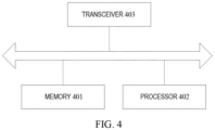
- FIG. 4 is a schematic structural diagram of an electronic device provided according to the embodiments of the present disclosure.
- the electronic device may include:
- a memory 401 and processor 402. The memory 401 configured to store computer programs and transmit the program code to the processor 402.
- the processor 402 can call and run the computer program from the memory 401 to implement the methods in the embodiments of the present disclosure.
- the processor 402 may be configured to execute the above method embodiments according to instructions in the computer program.
- the processor 402 may include, but is not limited to:
- DSP Digital Signal Processor
- ASIC Application Specific Integrated Circuit
- FPGA Field Programmable Gate Array
- the memory 401 includes, but is not limited to:
- Non-volatile memory can be read-only memory (ROM), programmable read-only memory (Programmable ROM, PROM), erasable programmable read-only memory (Erasable PROM, EPROM), electrically erasable programmable read-only memory (Electrically EEPROM, EEPROM) or flash memory.
- ROM read-only memory
- PROM programmable read-only memory
- Erasable PROM Erasable PROM
- EPROM erasable programmable read-only memory
- Electrically erasable programmable read-only memory Electrically erasable programmable read-only memory
- EEPROM electrically erasable programmable read-only memory
- flash memory may be a random access memory (RAM), which is used as an external cache.
- RAM random access memory
- RAM Random Access Memory
- SRAM static random access memory
- DRAM dynamic random access memory
- DRAM synchronous dynamic random access memory
- DDR SDRAM double data rate synchronous dynamic random access memory
- Enhanced SDRAM, ESDRAM enhanced synchronous dynamic random access memory
- SLDRAM synchronous link dynamic random access memory
- DR RAM Direct Rambus RAM
- the computer program can be divided into one or more modules, and the one or more modules are stored in the memory 401 and executed by the processor 402 to complete the methods provided in the present disclosure.
- the one or more modules may be a series of computer program instruction segments capable of completing specific functions. The instruction segment is used to describe the execution process of the computer program in the electronic device.
- the electronic device may further include: Transceiver 403, the transceiver 403 can be connected to the processor 402 or the memory 401.
- the processor 402 can control the transceiver 403 to communicate with other devices. Specifically, it can send information or data to other devices, or receive information or data sent by other devices.
- the transceiver 403 may include a transmitter and a receiver.
- the transceiver 403 may further include an antenna, and the number of antenna may be one or more.
- bus system where in addition to the data bus, the bus system also includes a power bus, a control bus and a status signal bus.
- the present disclosure further provides a computer storage medium on which a computer program is stored.
- the computer program When the computer program is executed by a computer, the computer can execute the method of the above method embodiments.
- the embodiments of the present disclosure further provide a computer program product including instructions, when the instructions are executed by a computer, cause the computer to perform the method of the above-mentioned method embodiments.
- the computer program product includes one or more computer instructions.
- the computer may be a general-purpose computer, a special purpose computer, a computer network, or other programmable device.
- the computer instructions may be stored in or transmitted from one computer-readable storage medium to another computer-readable storage medium, for example, the computer instructions may be transmitted from a website, computer, server, or data center in a wired (such as coaxial cable, optical fiber, digital subscriber line (DSL) or wireless (such as infrared, wireless, microwave, etc.) manner to another website, computer, server or data center.
- the computer-readable storage medium can be any available medium that can be accessed by a computer or a data storage device such as a server or data center integrated with one or more available media.
- the available media may be magnetic media (e.g., floppy disk, hard disk, magnetic tape), optical media (e.g., digital video disc (DVD)), or semiconductor media (e.g., solid state disk (SSD)), etc.
- an apparatus for lens barrel distance adjustment includes: a data processing circuit, an adjustment circuit, and a hall sensor, wherein:
- the hall sensor is configured to sense a magnetic induction intensity of a magnet related to a distance between left and right lens barrels of a head-mounted device, and output a corresponding first output voltage based on the magnetic induction intensity.
- the data processing circuit is connected to the hall sensor and the adjustment circuit and configured to obtain the first output voltage; in response to that the first output voltage indicates that an absolute value of a difference value between a distance between the left and right lens barrels and a pupillary distance of a user is greater than a predetermined threshold, send a control instruction corresponding to the difference value to the adjustment circuit, causing the adjustment circuit to adjust a distance between the left and right lens barrels based on the control instruction.
- the adjustment circuit is configured to receive the control instruction and adjust a distance between the left and right lens barrels based on the control instruction.
- the adjustment circuit is configured to adjust a distance between the left and right lens barrels based on the control instruction and drive the left lens barrel and/or the right lens barrel to move based on the control instruction.
- the adjustment circuit comprises a driving circuit and a stepper motor; wherein:
- the driving circuit is connected to the data processing circuit and the stepper motor and configured to receive the control instruction and generate a corresponding driving signal based on the control instruction.
- the stepper motor is configured to drive the left lens barrel and/or the right lens barrel to move based on the driving signal.
- the data processing circuit comprises: a first processing circuit and a second processing circuit, wherein:
- the first processing circuit is connected to a camera group and the second processing circuit and configured to obtain an eye image of user from the camera group and determine a pupillary distance of a user based on the eye image.
- the second processing circuit is connected to the hall sensor and the adjustment circuit and configured to obtain the first output voltage; in response to that the first output voltage indicates that an absolute value of a difference value between a distance between the left and right lens barrels and a pupillary distance of a user is greater than a predetermined threshold, send a control instruction corresponding to the difference value to the adjustment circuit, causing the adjustment circuit to adjust a distance between the left and right lens barrels based on the control instruction.
- the apparatus for lens barrel distance adjustment further comprises: a limiting circuit.
- the limiting circuit is connected to the data processing circuit and the left lens barrel and/or the right lens barrel and configured to generate a corresponding limit prompt signal when the left lens barrel and/or the right lens barrel move to a corresponding limit position;
- the data processing circuit is further configured to stop sending the control instruction to the adjustment circuit when the limit prompt signal is detected.
- the data processing circuit is further configured to: after sending the control instruction corresponding to the difference value to the adjustment circuit, obtain a second output voltage output by the hall sensor; in response to that the second output voltage indicates that an absolute value of a difference value between a distance between the left and right lens barrels and a pupillary distance of a user is not greater than the predetermined threshold, stop sending an instruction to the adjustment circuit that indicates the adjustment circuit to adjust a distance between the left and right lens barrels.
- a method for lens barrel distance adjustment includes:
- the method after sending a control instruction corresponding to the difference value to the adjustment circuit, the method further includes:
- the method further comprises: sending an instruction is stopped to the adjustment circuit that indicates the adjustment circuit to adjust the distance between the left and right lens barrels when a limit prompt signal is detected.
- a head-mounted device includes: a camera group, a data processing circuit, an adjustment circuit, and a hall sensor, wherein:
- the camera group is configured to take an eye image of a user.
- the hall sensor is configured to sense a magnetic induction intensity of a magnet related to a distance between left and right lens barrels of a head-mounted device, and output a corresponding first output voltage based on the magnetic induction intensity.
- the data processing circuit is connected to the hall sensor and the adjustment circuit and configured to obtain the first output voltage; in response to that the first output voltage indicates that an absolute value of a difference value between a distance between the left and right lens barrels and a pupillary distance of a user is greater than a predetermined threshold, send a control instruction corresponding to the difference value to the adjustment circuit, causing the adjustment circuit to adjust a distance between the left and right lens barrels based on the control instruction.
- the adjustment circuit is configured to receive the control instruction and adjust a distance between the left and right lens barrels based on the control instruction.
- an apparatus for lens barrel distance adjustment includes:
- an electronic device includes:
- a computer-readable storage medium on which a computer program is stored, and the computer program when executed by a processor, the above method is implemented.
- a computer program product including a computer program, the computer program when executed by a processor, the above method is implemented.
- the disclosed systems, apparatuses and methods can be implemented in other ways.
- the apparatus embodiments described above are only illustrative.
- the division of the modules is only a logical function division. In actual implementation, there may be other division methods.
- multiple modules or components may be combined or integrated. to another system, or some features can be ignored, or not implemented.
- the coupling or direct coupling or communication connection between each other shown or discussed may be through some interfaces, indirect coupling or communication connection of apparatuses or modules, and may be in electrical, mechanical or other forms.
- each functional module in each embodiment of the present disclosure can be integrated into one processing module, or each module can exist physically alone, or two or more modules can be integrated into one module.
Landscapes
- Physics & Mathematics (AREA)
- General Physics & Mathematics (AREA)
- Optics & Photonics (AREA)
- Stereoscopic And Panoramic Photography (AREA)
- Lens Barrels (AREA)
- Eye Examination Apparatus (AREA)
Applications Claiming Priority (2)
| Application Number | Priority Date | Filing Date | Title |
|---|---|---|---|
| CN202210114629.3A CN116560082A (zh) | 2022-01-30 | 2022-01-30 | 瞳距调节装置、方法、设备及计算机介质 |
| PCT/CN2023/071359 WO2023143017A1 (zh) | 2022-01-30 | 2023-01-09 | 镜筒距离调节装置、方法、设备及计算机介质 |
Publications (2)
| Publication Number | Publication Date |
|---|---|
| EP4407364A1 true EP4407364A1 (de) | 2024-07-31 |
| EP4407364A4 EP4407364A4 (de) | 2025-03-26 |
Family
ID=87470645
Family Applications (1)
| Application Number | Title | Priority Date | Filing Date |
|---|---|---|---|
| EP23745900.3A Pending EP4407364A4 (de) | 2022-01-30 | 2023-01-09 | Vorrichtung und verfahren zur einstellung des abstandes zwischen linsenzylindern, vorrichtung und computermedium |
Country Status (4)
| Country | Link |
|---|---|
| US (2) | US12153281B2 (de) |
| EP (1) | EP4407364A4 (de) |
| CN (1) | CN116560082A (de) |
| WO (1) | WO2023143017A1 (de) |
Family Cites Families (21)
| Publication number | Priority date | Publication date | Assignee | Title |
|---|---|---|---|---|
| US5486841A (en) * | 1992-06-17 | 1996-01-23 | Sony Corporation | Glasses type display apparatus |
| KR101726676B1 (ko) * | 2015-05-20 | 2017-04-14 | 엘지전자 주식회사 | 헤드 마운티드 디스플레이 |
| CN105425397A (zh) * | 2016-01-01 | 2016-03-23 | 赵山山 | 一种头戴式显示器的自动调节方法、系统和装置 |
| US20170344107A1 (en) * | 2016-05-25 | 2017-11-30 | Intel Corporation | Automatic view adjustments for computing devices based on interpupillary distances associated with their users |
| US10690991B1 (en) * | 2016-09-02 | 2020-06-23 | Apple Inc. | Adjustable lens systems |
| CN106686365A (zh) * | 2016-12-16 | 2017-05-17 | 歌尔科技有限公司 | 用于头戴显示设备的镜头调节方法、装置及头戴显示设备 |
| TWM545271U (zh) * | 2017-02-09 | 2017-07-11 | Largan Digital Co Ltd | 雙鏡頭驅動裝置與電子裝置 |
| US10962777B1 (en) * | 2017-05-01 | 2021-03-30 | Facebook Technologies, Llc | Devices and methods for adjusting lens positions based on encoded light patterns |
| CN207706338U (zh) * | 2017-12-04 | 2018-08-07 | 深圳市冠旭电子股份有限公司 | Vr智能头戴设备和vr图像显示系统 |
| US10823970B2 (en) * | 2018-08-23 | 2020-11-03 | Apple Inc. | Head-mounted electronic display device with lens position sensing |
| CN110398840B (zh) * | 2019-07-19 | 2021-10-15 | Oppo广东移动通信有限公司 | 调整光心距离的方法、头戴设备和存储介质 |
| US11402642B2 (en) * | 2019-11-03 | 2022-08-02 | Facebook Technologies, Llc | Head-mounted display assemblies and related methods for interpupillary distance adjustments |
| CN210835442U (zh) * | 2019-11-29 | 2020-06-23 | 歌尔科技有限公司 | 一种用于vr设备的瞳距调节装置及vr设备 |
| CN111025637A (zh) * | 2019-12-06 | 2020-04-17 | Oppo广东移动通信有限公司 | 系带调节装置和穿戴设备 |
| CN111638601B (zh) * | 2020-06-30 | 2022-08-09 | 京东方科技集团股份有限公司 | 一种智能眼镜 |
| CN112630972B (zh) * | 2020-12-29 | 2024-10-29 | 青岛小鸟看看科技有限公司 | 一种vr眼镜 |
| CN113489966B (zh) * | 2021-05-17 | 2022-07-26 | 青岛小鸟看看科技有限公司 | Vr设备瞳距调节位置检测系统、方法 |
| CN113419344A (zh) | 2021-05-20 | 2021-09-21 | 歌尔股份有限公司 | 虚拟现实装置的瞳距调节方法、虚拟现实装置及介质 |
| CN113709622B (zh) * | 2021-09-23 | 2022-11-01 | 歌尔科技有限公司 | 头戴电子设备状态检测方法、装置、头戴电子设备及介质 |
| CN113985610A (zh) * | 2021-10-29 | 2022-01-28 | 歌尔光学科技有限公司 | 头戴显示设备的控制方法、头戴显示设备及存储介质 |
| CN116990965A (zh) * | 2022-04-26 | 2023-11-03 | 华为技术有限公司 | 瞳距调节方法、头戴显示设备和可读存储介质 |
-
2022
- 2022-01-30 CN CN202210114629.3A patent/CN116560082A/zh active Pending
-
2023
- 2023-01-09 EP EP23745900.3A patent/EP4407364A4/de active Pending
- 2023-01-09 WO PCT/CN2023/071359 patent/WO2023143017A1/zh not_active Ceased
-
2024
- 2024-04-24 US US18/644,951 patent/US12153281B2/en active Active
- 2024-10-25 US US18/927,048 patent/US12607824B2/en active Active
Also Published As
| Publication number | Publication date |
|---|---|
| EP4407364A4 (de) | 2025-03-26 |
| US20240280785A1 (en) | 2024-08-22 |
| US12153281B2 (en) | 2024-11-26 |
| WO2023143017A1 (zh) | 2023-08-03 |
| US20250052977A1 (en) | 2025-02-13 |
| CN116560082A (zh) | 2023-08-08 |
| US12607824B2 (en) | 2026-04-21 |
Similar Documents
| Publication | Publication Date | Title |
|---|---|---|
| KR102644273B1 (ko) | 상이한 fov를 갖는 카메라들을 이용한 시차 추정 시스템 및 방법 | |
| US8351131B2 (en) | Lens apparatus | |
| CN107613262B (zh) | 一种视觉信息处理系统与方法 | |
| US10823582B2 (en) | Angle detection device and method of multi-turn servo, and multi-turn servo | |
| US11110607B2 (en) | Servo output shaft rotational angle calibration method and system and robot using the same | |
| US10469732B2 (en) | Method and device for controlling electronic apparatus, and electronic apparatus | |
| CN109955245A (zh) | 一种机器人的避障方法、系统及机器人 | |
| US9961254B2 (en) | Electronic device, control method for same, and storage medium | |
| EP4660767A1 (de) | Verarbeitungsverfahren und system zur anzeige einer vollständigen kartengrenze und zugehörige vorrichtung | |
| CN108177146A (zh) | 机器人头部的控制方法、装置及计算设备 | |
| US11020853B2 (en) | Robot, method for controlling motion of a robot and non-transitory readable medium | |
| CN108989491B (zh) | 电子装置、速度控制方法及相关产品 | |
| CN108924520A (zh) | 传输控制方法、装置、控制器、拍摄设备及飞行器 | |
| EP2981074A1 (de) | Anzeigevorrichtung, anzeigeverfahren und anzeigeprogramm | |
| EP4407364A1 (de) | Vorrichtung und verfahren zur einstellung des abstandes zwischen linsenzylindern, vorrichtung und computermedium | |
| GB2522748A (en) | Detecting pause in audible input to device | |
| US9948845B2 (en) | Device for multi-angle photographing in eyeglasses and eyeglasses including the device | |
| CN114280781B (zh) | 智能眼镜、智能眼镜的控制方法及装置 | |
| US20250347893A1 (en) | Virtual reality device, lens barrel positional state detection method and apparatus therefor, and medium | |
| US10981275B2 (en) | Robot control method, apparatus and storage medium with the same | |
| US10564631B2 (en) | Servo movement control method, device, and terminal device | |
| US11115594B2 (en) | Shutter speed adjusting method and apparatus, and robot using the same | |
| CN110855885B (zh) | 一种镜头转动的控制方法及装置 | |
| CN110798607A (zh) | 拍摄状态调节方法及装置 | |
| CN109040349B (zh) | 电子装置、驱动控制方法及相关产品 |
Legal Events
| Date | Code | Title | Description |
|---|---|---|---|
| STAA | Information on the status of an ep patent application or granted ep patent |
Free format text: STATUS: THE INTERNATIONAL PUBLICATION HAS BEEN MADE |
|
| PUAI | Public reference made under article 153(3) epc to a published international application that has entered the european phase |
Free format text: ORIGINAL CODE: 0009012 |
|
| STAA | Information on the status of an ep patent application or granted ep patent |
Free format text: STATUS: REQUEST FOR EXAMINATION WAS MADE |
|
| 17P | Request for examination filed |
Effective date: 20240423 |
|
| AK | Designated contracting states |
Kind code of ref document: A1 Designated state(s): AL AT BE BG CH CY CZ DE DK EE ES FI FR GB GR HR HU IE IS IT LI LT LU LV MC ME MK MT NL NO PL PT RO RS SE SI SK SM TR |
|
| REG | Reference to a national code |
Ref country code: DE Ref legal event code: R079 Free format text: PREVIOUS MAIN CLASS: G02B0027010000 Ipc: G02B0007120000 |
|
| A4 | Supplementary search report drawn up and despatched |
Effective date: 20250221 |
|
| RIC1 | Information provided on ipc code assigned before grant |
Ipc: G02B 27/01 20060101ALN20250217BHEP Ipc: G02B 7/12 20210101AFI20250217BHEP |
|
| DAV | Request for validation of the european patent (deleted) | ||
| DAX | Request for extension of the european patent (deleted) |