EP4407271B1 - Klemmsystem für zusatzgeräte auf einer picatinny-schiene - Google Patents
Klemmsystem für zusatzgeräte auf einer picatinny-schiene Download PDFInfo
- Publication number
- EP4407271B1 EP4407271B1 EP24000001.8A EP24000001A EP4407271B1 EP 4407271 B1 EP4407271 B1 EP 4407271B1 EP 24000001 A EP24000001 A EP 24000001A EP 4407271 B1 EP4407271 B1 EP 4407271B1
- Authority
- EP
- European Patent Office
- Prior art keywords
- lever
- picatinny rail
- clamping system
- housing
- clamping
- Prior art date
- Legal status (The legal status is an assumption and is not a legal conclusion. Google has not performed a legal analysis and makes no representation as to the accuracy of the status listed.)
- Active
Links
Images




Classifications
-
- F—MECHANICAL ENGINEERING; LIGHTING; HEATING; WEAPONS; BLASTING
- F41—WEAPONS
- F41G—WEAPON SIGHTS; AIMING
- F41G11/00—Details of sighting or aiming apparatus; Accessories
- F41G11/001—Means for mounting sighting or aiming devices on firearms
- F41G11/003—Mountings with a dove tail element, e.g. "Picatinny rail systems"
Definitions
- Self-loading rifles such as assault rifles for military use, are often equipped with additional devices such as telescopic sights, red dot sights, lights, lasers, bipods, etc.
- these weapons are usually equipped with dovetail rails on the top of their system, which are manufactured according to MIL-STD-1913 or standards based on MIL-STD-1913.
- Dovetail rails of this type are referred to as "Picatinny rails" and consist of a profile running in the direction of fire, which is provided with transverse grooves at regular intervals.
- the mounting systems for attaching additional devices are equipped with at least one recoil lug on the side facing the Picatinny rail, which engages into one of the transverse grooves.
- the handguard and other parts of the weapon can also be equipped with Picatinny rails, whereby the Picatinny rails can be an integral part of a component of the weapon or as separate parts that can be connected to the corresponding weapon component, for example by a screw connection.
- a clamping system for additional devices on Picatinny rails is used, for example, in the EP 2 339 287 A2
- This mounting system has either a nut system or a lever system for clamping onto the Picatinny rail.
- the dimensions of the lever system were designed in such a way that the relatively long lever allows a very high clamping force to be applied, and the curved shape of the lever makes it easy to operate even when wearing gloves. If, for example, rifle scopes are attached using such clamping systems, the adjustment turrets for parallax compensation, illumination unit, and windage adjustment attached to the left and right of the rifle scope protrude further laterally than the nut or lever system. The clamping system therefore does not interfere with the use of the weapon.
- This mounting system is also very suitable for clamping night vision or thermal imaging attachments. Even these very wide and heavy additional devices usually protrude significantly beyond the clamping system with their bodies.
- a further advantage of the lever system also compared to the nut system disclosed in the same application, is its tool-free operation and the always constant clamping torque.
- the clamping system is very wide, as the lever extends laterally well beyond the width of the Picatinny rail. This is because the contact surface of the movable clamping jaw to the lever is located to the side of the Picatinny rail. Furthermore, the lever's rotation axis is offset even further to the outside of the Picatinny rail than the contact surface of the movable clamping jaw.
- Widely used military self-loading weapons such as AR15 and AR10-type weapons, feature a Picatinny rail and a rear-mounted charging handle on top of their receiver.
- Rear-mounted means that the charging handle's controls extend laterally beyond the width of the Picatinny rail, but are located behind the end of the Picatinny rail facing the shooter. This eliminates the need for clamping systems that protrude far to the side when operating the charging handle.
- bolt-action rifles often feature Picatinny rails on their receivers.
- clamping systems that protrude far to the side are not a problem if the clamping system controls are located on the closed left side of the receiver when viewed in the direction of fire, and the accessories are designed accordingly.
- the receivers of bolt-action rifles typically have the ejection port on the right side. In this case, clamping systems that protrude far can impede case ejection. Therefore, the operating elements of the mounting systems on bolt-action rifles are usually installed on the left side of the weapon.
- Single magnification red dot sights with a closed housing are often used as aiming optics for various types of weapons.
- many devices of this type have the Housing for the battery or the dial for the various illumination levels.
- the dial or the battery housing often form a single unit.
- Recent developments have been toward very slim optics housings with no protruding components.
- One example of this design is the ACRO from Aimpoint.
- a very slim clamping system offers significant advantages to prevent the optics from snagging on the shooter's clothing and to improve the handling of the entire system consisting of weapon and optics.
- clamping systems operated by nuts or screws are not an option.
- the advantage of such clamping systems is the high clamping force that can be applied using the operating key.
- Such clamping systems are therefore also suitable for use on heavy machine guns, for example.
- the US 6,606,813 B1 shows a clamping system that is particularly low-profile and can be operated without tools using a clamping lever.
- Fig. 10 It can be seen that the pivot axis of the lever is significantly further from the center of the Picatinny rail than the outer surface of the movable clamping jaw, which means that the lever protrudes relatively far to the side.
- the US 2013/0312307 A1 shows a clamping system with a relatively small lateral projection.
- a spring transmits a tensile force to a wedge-shaped component, which in turn transmits the clamping force to the movable clamping jaw.
- the wedge-shaped component is moved against the spring force using a push button.
- the disadvantage of this system is the relatively low clamping force exerted by the spring and the wedge-shaped component.
- the US 2010/0107467 A1 reveals a clamping system that can be operated without tools using a lever.
- Fig. 2 and Fig. 5 It can be seen that the vertically arranged rotation axes of the levers are significantly further away from the center of the Picatinny rail than the outer surfaces of the clamping jaws, which results in a relatively large lateral overhang of the clamping levers.
- the US 2017/0261288 A1 discloses a clamping system that has very little lateral overhang and can be operated without tools. Clamping is achieved by means of a screw-like component whose head has raised and recessed sections around its circumference. These raised and recessed sections serve, on the one hand, to secure the clamped section in the clamped position (see Fig. 10 and Fig. 24), on the other hand, they provide the necessary grip to operate the component by hand.
- the torque applied to the screw-like component by hand alone, and consequently the clamping force transferred to the Picatinny rail, is relatively low.
- the WO 2005/083351 A1 shows a clamping system that can be operated without tools using a horizontally pivoting lever.
- Figures 2 and 3 It is evident that the vertically arranged pivot axis is significantly farther from the center of the Picatinny rail than the outer surface of the movable clamping jaw. This arrangement results in the mounting device projecting relatively far laterally.
- Fig. 1 It can be seen that the lever is completely integrated into the housing in its closed position, but only because the outer wall of the housing has been extended sufficiently far beyond the outer surface of the movable clamping jaw.
- the EP 3 783 294 B1 discloses a clamping system in which the lever's pivot axis is positioned horizontally. To apply the clamping force, the lever must be pivoted upward, where it rests against the housing, resulting in a relatively large minimum housing height. Here, too, the lever's pivot axis is located farther from the center of the Picatinny rail than the outer surface of the movable clamping jaw, resulting in a relatively large lateral overhang.
- the objective of the invention is to create a clamping system for accessories on Picatinny rails that has the smallest possible lateral overhang over the Picatinny rail and can be operated without tools.
- the clamping force should be sufficiently high to allow safe use on all types of weapons, and it should be possible to mount it at different heights.
- the clamping device comprises a horizontally pivoting lever with an eccentric cam and a movable clamping jaw for its operation.
- the contact surface of the movable clamping jaw with the eccentric cam on the lever is located above the surface and within the width of the Picatinny rail. This enables a significantly slimmer design of the mounting device, as the contact surface has been relocated from the outside of the movable clamping jaw toward the center of the Picatinny rail.
- the lever By moving the contact surface towards the center of the Picatinny rail, the lever can be fully integrated into the slim housing when closed.
- the lever is equipped with a safety catch and, due to its relatively long length, protrudes beyond the front or rear end of the housing when locked, at least with the safety catch. This allows the lever to be operated easily and safely even while wearing gloves, and its length generates a relatively large clamping force.
- the vertical arrangement of the lever's pivot axis allows a relatively low overall height of the housing, since this arrangement of the clamping lever can be swiveled horizontally and does not have to be folded upwards onto the housing.
- the housing has only one clamping system according to the invention.
- multiple clamping systems can be installed simultaneously in one housing.
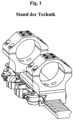
- the Fig. 1 shows a clamping system according to the EP 2 339 287 A2 State-of-the-art.
- the clamping system is shown clamped onto a Picatinny rail. It is evident that the lever extends considerably laterally beyond the Picatinny rail, as the contact surface of the movable clamping jaw with the lever's eccentric is positioned laterally next to the Picatinny rail. Furthermore, the lever's rotation axis is offset even further outward from the Picatinny rail than the contact surface of the movable clamping jaw with the lever's eccentric. Due to its design, the contact surface of the movable clamping jaw is formed by its outer surface.
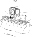
- the height H1 of the housing 2 determines the height H2 of the optical axis of the additional device 4. Both dimensions are measured from the surface of the Picatinny rail 1 on which the housing 2 rests with its base surface 50 (see Fig. 3 ) when the clamping system is clamped. Different types of weapons require different heights for the various additional devices. If, for example, a lamp or a laser is to be attached using the clamping system according to the invention, it is advisable to select the technically lowest possible height H1. If, for example, a red dot sight is to be attached to a repeating rifle, the height H1 should be lower than when attaching the same red dot sight to an assault rifle.
- the height H1 is highly dependent on the height of the cheek rest of the shoulder rest or the stock of the weapon.
- the opening 5 in the housing 2 serves to save weight. If the housing 2 is to be designed with a greater height H1 than in Fig. 1 shown are built, the Height of opening 5. If the housing 2 is to be built at its lowest possible height H1, opening 5 can be omitted.
- Fig. 2 Shows the charging handle 6 in its forward end position. To charge the weapon, the charging handle 6 must be pulled by hand in the groove 7 to its rear end position. With clamping systems that protrude far, this movement can cause hand injuries.
- the housing 2 has a very narrow design. No components of the clamping system according to the invention installed therein protrude laterally beyond the housing 2.
- the housing 2 has bevels at the front and rear, and the movable clamping jaw 8 has rounded portions on its claw 9.
- the lever 10 is fully integrated into the housing 2 when closed.
- Fig. 3 shows the lever 10 with the groove 11 and the transverse bore 12 therein.
- a securing element in the form of a pawl 13 has a bore 14. With the aid of the clamping sleeve 15, the pawl 13 is rotatably mounted in the lever 10.
- the compression spring 51 presses the pawl 13 with its stop surface 16 against the bottom of the groove 11.
- the locking pin 17 is fixed in the bore 18 in the housing 2 by gluing or pressing and serves to secure the lever 10 against unintentional opening.
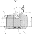
- the pivot pin 19 (see Fig. 6 ) of the lever 10 is mounted in the elongated hole 20 of the base body 2 so that it can rotate and be moved transversely to the direction of fire.
- the position of the lever 10 can be adjusted transversely to the Picatinny rail 1. This allows manufacturing tolerances on the prism of the Picatinny rail 1 and in the clamping system to be compensated for and the desired clamping force to be set.
- the plastic pin 22 is inserted into the blind hole 49, which runs axially parallel to the internal thread 48 and partially protrudes into the internal thread 48. The thread flanks of the adjusting screw 21 thus deform the plastic pin 22, which secures the adjusting screw 21 against unintentional twisting.
- the claw 9 of the movable clamping jaw 8 is clamped by the eccentric cam 23 of the lever 10 against the first lower flank 24 of the Picatinny rail 1 drawn (see also Fig. 2 ).
- the housing 2 is supported with its first fixed jaw 26 and its second fixed jaw 27 on the opposite second lower flank 25 of the Picatinny rail 1 and the base body 2 is pulled onto the surface of the Picatinny rail 1.
- the stop 28 on the housing 2 serves to absorb the recoil forces. When clamped, it engages in one of the transverse grooves of the Picatinny rail 1 and rests with its front stop surface 29 against the rear wall of the corresponding transverse groove.
- Fig. 4 the run-on bevel 30 on the locking pawl 13 is visible. If the clamping system is brought into the clamped position by pivoting the lever 10, the locking pawl 13 slides along the run-on bevel 30 over the locking pin 17. The compression spring 51, see Fig. 3 , is compressed. As soon as the locking pin 17 has been overcome, the locking pawl 13 engages in the undercut between the locking pin 17 and the locking surface 31 on the housing 2.
- Fig. 5 The movable clamping jaw 8 with its contact surface 32 can be seen.
- the eccentric cam 23 (see Fig. 3 ) on the lever 10 rolls on the contact surface 32 when it is actuated.
- the first compression spring 33 and the second compression spring 34 see Fig. 3 , ensure constant contact of the surface 32 with the eccentric cam 23 over the entire pivoting range of the lever 10.
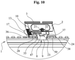
- the movable clamping jaw 8 is fixed by the first extension 35 in the first guide groove 36 (see Fig. 10 ) and by the second extension 37 in the second guide groove 38 (see Fig. 10 ) is mounted in the housing 2.
- the support plate 39 see Fig. 3 , is screwed into the housing 2 by means of the countersunk screw 40 and supports the two compression springs 33 and 34.
- Fig. 6 shows the lever 10 with the eccentric cam 23, on which the free surface 41 with its distance F to the axis of rotation 43 of the lever 10 and the radius surface 42 with its radius R around the axis of rotation 43 of the lever 10 are located.
- the radius R is greater than the distance F, whereby the difference between the two dimensions was chosen to be large enough that the claw 9 of the movable clamping jaw 8 releases the Picatinny rail 1 when the clamping system is open and the mounting device can be removed.
- Fig. 9 illustrates that when clamped onto the Picatinny rail 1, the contact surface 32 of the movable clamping jaw 8 to the eccentric cam 23 of the pivot lever 10 lies above the surface and within the width B of the Picatinny rail 1.
- the adjusting screw 21 presses against the pivot pin 19, whereby the eccentric cam 23 is pressed with the radius surface 42 against the contact surface 32 of the movable clamping jaw 8.
- the axis of rotation 43 of the lever 10 is closer to the center 46 of the Picatinny rail 1 than the outer surface 47 of the movable clamping jaw 8.
- the contact between the lever and the movable clamping jaw always occurs on an outer surface of the clamping jaw.
- this contact surface was relocated above the surface and within the width B of the Picatinny rail 1, thereby achieving a significantly narrower design of the overall system. Furthermore, it is evident that the rotation axis 43 of the lever 10 lies within the width B of the Picatinny rail 1, which also contributes to a significantly narrower design of the overall system.
- the upwardly open, gray-shaded field in Fig. 9 defines the area in which the contact surface 32 is located in a clamping system according to the invention.
- the axis of rotation 43 of the lever 10 also runs through this field, it is closer to the center 46 of the Picatinny rail 1 than the outer surface 47 of the movable clamping jaw 8, which also contributes to a smaller lateral overhang.
- Fig. 10 It can be seen that at least the locking pawl 13 protrudes beyond the front end of the housing 2. This makes it easier to move the lever 10 from the clamped to the released position by the operator actuating the locking pawl 13 with one finger, holding it pressed, and simultaneously pulling the lever 10 with its help. Depending on the design of the clamping system and the housing 2, it is conceivable that the lever 10 itself also partially protrudes beyond the front end of the housing 2.
- Fig. 2 the lever 10 is shown on the left side of the housing 2 and pointing forward in the firing direction. In other versions not shown in the Figures 2 to 10 In the embodiments of the invention shown, the lever 10 can be located on the right side of the housing 2 and/or pointing rearward in the firing direction. Depending on the design of the interface 3, the housing 2 can be rotated 180° and placed on the Picatinny rail 1.
- the pawl 13 is not rotatably mounted, but is designed to be displaceable against a spring force relative to the lever 10.
- the spring installed between the lever 10 and the rotatably mounted pawl 13 is designed as a leg spring.
- the undercut into which the locking pawl 13 engages when clamped on the Picatinny rail 1 is formed, for example, by a correspondingly shaped groove in the housing 2.
- the clamping system is simpler for cost reasons, ie, it is designed without a locking pawl 13 to prevent unintentional opening of the lever 10.
- the lever 10 itself partially projects beyond the front or rear end of the housing 2.
Landscapes
- Engineering & Computer Science (AREA)
- General Engineering & Computer Science (AREA)
- Clamps And Clips (AREA)
Priority Applications (1)
| Application Number | Priority Date | Filing Date | Title |
|---|---|---|---|
| HRP20250978TT HRP20250978T1 (hr) | 2023-01-25 | 2024-01-04 | Stezni sustav za dodatke na picatinny šini |
Applications Claiming Priority (1)
| Application Number | Priority Date | Filing Date | Title |
|---|---|---|---|
| DE202023000163.3U DE202023000163U1 (de) | 2023-01-25 | 2023-01-25 | Klemmsystem für Zusatzgeräte auf einer Picatinny-Schiene |
Publications (2)
| Publication Number | Publication Date |
|---|---|
| EP4407271A1 EP4407271A1 (de) | 2024-07-31 |
| EP4407271B1 true EP4407271B1 (de) | 2025-05-28 |
Family
ID=85773023
Family Applications (1)
| Application Number | Title | Priority Date | Filing Date |
|---|---|---|---|
| EP24000001.8A Active EP4407271B1 (de) | 2023-01-25 | 2024-01-04 | Klemmsystem für zusatzgeräte auf einer picatinny-schiene |
Country Status (7)
| Country | Link |
|---|---|
| US (1) | US12571613B2 (pl) |
| EP (1) | EP4407271B1 (pl) |
| DE (1) | DE202023000163U1 (pl) |
| FI (1) | FI4407271T3 (pl) |
| HR (1) | HRP20250978T1 (pl) |
| HU (1) | HUE072555T2 (pl) |
| PL (1) | PL4407271T3 (pl) |
Families Citing this family (2)
| Publication number | Priority date | Publication date | Assignee | Title |
|---|---|---|---|---|
| USD1034733S1 (en) | 2021-01-13 | 2024-07-09 | Samsun Yurt Savunma Sanayi Ve Ticaret Anonim Sirketi Corporation | Optical sight system |
| USD1045002S1 (en) * | 2022-07-18 | 2024-10-01 | Samsun Yurt Savunma Sanayi Ve Ticaret Anonim Sirketi Corporation | Gun sight |
Family Cites Families (20)
| Publication number | Priority date | Publication date | Assignee | Title |
|---|---|---|---|---|
| DE1256113B (de) * | 1963-11-13 | 1967-12-07 | Heckler & Koch Gmbh | Traeger fuer ein optisches Zielgeraet |
| US3324558A (en) * | 1965-08-06 | 1967-06-13 | Arthur E Hart | Means for separably attaching sights to guns |
| US6606813B1 (en) | 2002-03-08 | 2003-08-19 | Exponent, Inc. | Weapon accessory mounting apparatus |
| DE20313331U1 (de) * | 2003-08-28 | 2003-11-20 | Henneberger, Frank, 97702 Münnerstadt | Zielgerätehalterung |
| DE102004008211B4 (de) | 2004-02-19 | 2006-04-13 | Heckler & Koch Gmbh | Montageeinrichtung für Feuerwaffen |
| US7308772B1 (en) * | 2005-12-02 | 2007-12-18 | Millett Industries, Inc. | Articulated sight mount |
| US7802395B1 (en) * | 2006-12-11 | 2010-09-28 | Swan Richard E | Mounting assembly with positive stop for actuator arm |
| US8201355B2 (en) * | 2008-08-05 | 2012-06-19 | L-3 Insight Technology Incorporated | Rail attachment mechanism |
| US20100107467A1 (en) | 2008-10-30 | 2010-05-06 | Machining Technologies, Inc. | Self adjusting throw lever and rail clamp system |
| DE202009017398U1 (de) | 2009-12-22 | 2010-04-01 | G. Recknagel E.K. Precision Tradition Technology | Klemmsystem für Zusatzgeräte auf einer Picatinny-Schiene |
| DE202011002180U1 (de) | 2011-02-01 | 2011-08-16 | Christian Scherpf | Zielfernrohrmontage |
| US8813412B2 (en) | 2012-05-22 | 2014-08-26 | Steven M. Rorick | Quick detachable firearm accessory mount |
| US9784536B2 (en) * | 2014-04-12 | 2017-10-10 | Jason William Boswell | Weapon light mount |
| US20160216062A1 (en) * | 2014-12-24 | 2016-07-28 | Remy Trotabas | Quick disconnect accessory mount and safety latch |
| US10132596B2 (en) | 2015-10-13 | 2018-11-20 | Philippe Bartoszewicz | Technologies for firearm accessory mounting |
| US10161704B1 (en) * | 2017-08-11 | 2018-12-25 | Darryl S. Lee | Firearm adapter configured to mount to a firearm frame |
| DE202019106611U1 (de) | 2019-08-20 | 2019-12-18 | Michael Ali Kilic | Zielfernrohr-Montagesystem mit Verriegelungshebel |
| US10907937B1 (en) * | 2019-08-23 | 2021-02-02 | Keng's Firearms Specialty, Inc. | Firearm mount and clamp assembly |
| US20220333900A1 (en) * | 2021-04-16 | 2022-10-20 | Joseph Scott Beasley | Quick detach optic mount |
| US12359685B2 (en) * | 2021-09-01 | 2025-07-15 | Shadow Tech, LLC | Clamp with cam lever |
-
2023
- 2023-01-25 DE DE202023000163.3U patent/DE202023000163U1/de active Active
-
2024
- 2024-01-04 EP EP24000001.8A patent/EP4407271B1/de active Active
- 2024-01-04 PL PL24000001.8T patent/PL4407271T3/pl unknown
- 2024-01-04 HU HUE24000001A patent/HUE072555T2/hu unknown
- 2024-01-04 HR HRP20250978TT patent/HRP20250978T1/hr unknown
- 2024-01-04 FI FIEP24000001.8T patent/FI4407271T3/fi active
- 2024-01-19 US US18/417,008 patent/US12571613B2/en active Active
Also Published As
| Publication number | Publication date |
|---|---|
| US12571613B2 (en) | 2026-03-10 |
| HRP20250978T1 (hr) | 2025-10-24 |
| DE202023000163U1 (de) | 2023-03-15 |
| HUE072555T2 (hu) | 2025-11-28 |
| FI4407271T3 (fi) | 2025-08-25 |
| PL4407271T3 (pl) | 2025-11-17 |
| EP4407271A1 (de) | 2024-07-31 |
| US20240247914A1 (en) | 2024-07-25 |
Similar Documents
| Publication | Publication Date | Title |
|---|---|---|
| EP2122292B1 (de) | Anschlussstück und anschlussstück mit visierelement | |
| EP1716383B1 (de) | Montageeinrichtung für feuerwaffen | |
| DE19903321B4 (de) | Ladehebelanordnung für eine Handfeuerwaffe | |
| DE102018132756B4 (de) | Umrüstsatz für eine Kurzwaffe | |
| EP2956732B1 (de) | Universelle zielfernrohrmontage für handfeuerwaffen | |
| CH654908A5 (de) | Schusswaffe fuer das praezisionsschiessen. | |
| EP4407271A1 (de) | Klemmsystem für zusatzgeräte auf einer picatinny-schiene | |
| EP3368853A1 (de) | Adapter zur anbringung wenigstens einer zusatzeinrichtung an einer selbstlade-feuerwaffe und mit diesem ausgestattete selbstlade-feuerwaffe | |
| EP1200790A2 (de) | Schulterstütze für eine handfeuerwaffe sowie sperrhebel für eine solche schulterstütze | |
| DE19742248A1 (de) | Verbesserungen an bzw. bezüglich von Feuerwaffen | |
| EP3553457A1 (de) | Vorrichtung zur variablen befestigung zweier optikeinrichtungen an einer waffe | |
| DE102007005142B4 (de) | Anschlussstück | |
| EP3973244B1 (de) | Obergehäuse für eine feuerwaffe | |
| EP4610589A1 (de) | Vorrichtung zur befestigung einer zieleinrichtung an einer schusswaffe | |
| WO2008119098A1 (de) | Befestigungsschiene für feuerwaffe | |
| EP4224110B1 (de) | Verstellbare visiereinrichtung | |
| DE102006024508B4 (de) | Halterung für Zusatzgeräte an Feuerwaffen | |
| EP4116664A1 (de) | Montagesystem für zieleinrichtung und zusatzeinrichtung | |
| DE102005005232A1 (de) | Montage zur Verbindung von Optiken mit Schusswaffen | |
| DE202018101992U1 (de) | Vorrichtung zur variablen Befestigung zweier Optikeinrichtungen an einer Waffe | |
| EP4296604B1 (de) | Längeneinstellbare schaftkappe mit integrierter rückstossdämpfung für eine waffe, insbesondere eine jagd- oder sportwaffe | |
| DE10002587A1 (de) | Tiefliegende Halterungsvorrichtung zur Befestigung eines Zielfernrohrs auf Jagd- und Sportwaffen | |
| EP0117845A1 (de) | Visiereinrichtung für Waffen | |
| DE202019106701U1 (de) | Kompakte Montagevorrichtung | |
| EP4682460A1 (de) | Montagevorrichtung zur befestigung eines zusatzteils an einer kurzwaffe |
Legal Events
| Date | Code | Title | Description |
|---|---|---|---|
| REG | Reference to a national code |
Ref country code: HR Ref legal event code: TUEP Ref document number: P20250978T Country of ref document: HR |
|
| PUAI | Public reference made under article 153(3) epc to a published international application that has entered the european phase |
Free format text: ORIGINAL CODE: 0009012 |
|
| STAA | Information on the status of an ep patent application or granted ep patent |
Free format text: STATUS: THE APPLICATION HAS BEEN PUBLISHED |
|
| AK | Designated contracting states |
Kind code of ref document: A1 Designated state(s): AL AT BE BG CH CY CZ DE DK EE ES FI FR GB GR HR HU IE IS IT LI LT LU LV MC ME MK MT NL NO PL PT RO RS SE SI SK SM TR |
|
| STAA | Information on the status of an ep patent application or granted ep patent |
Free format text: STATUS: REQUEST FOR EXAMINATION WAS MADE |
|
| 17P | Request for examination filed |
Effective date: 20240819 |
|
| RBV | Designated contracting states (corrected) |
Designated state(s): AL AT BE BG CH CY CZ DE DK EE ES FI FR GB GR HR HU IE IS IT LI LT LU LV MC ME MK MT NL NO PL PT RO RS SE SI SK SM TR |
|
| GRAP | Despatch of communication of intention to grant a patent |
Free format text: ORIGINAL CODE: EPIDOSNIGR1 |
|
| STAA | Information on the status of an ep patent application or granted ep patent |
Free format text: STATUS: GRANT OF PATENT IS INTENDED |
|
| INTG | Intention to grant announced |
Effective date: 20250220 |
|
| GRAS | Grant fee paid |
Free format text: ORIGINAL CODE: EPIDOSNIGR3 |
|
| GRAA | (expected) grant |
Free format text: ORIGINAL CODE: 0009210 |
|
| STAA | Information on the status of an ep patent application or granted ep patent |
Free format text: STATUS: THE PATENT HAS BEEN GRANTED |
|
| AK | Designated contracting states |
Kind code of ref document: B1 Designated state(s): AL AT BE BG CH CY CZ DE DK EE ES FI FR GB GR HR HU IE IS IT LI LT LU LV MC ME MK MT NL NO PL PT RO RS SE SI SK SM TR |
|
| REG | Reference to a national code |
Ref country code: GB Ref legal event code: FG4D Free format text: NOT ENGLISH |
|
| REG | Reference to a national code |
Ref country code: CH Ref legal event code: EP |
|
| REG | Reference to a national code |
Ref country code: IE Ref legal event code: FG4D Free format text: LANGUAGE OF EP DOCUMENT: GERMAN Ref country code: DE Ref legal event code: R096 Ref document number: 502024000049 Country of ref document: DE |
|
| REG | Reference to a national code |
Ref country code: FI Ref legal event code: FGE |
|
| REG | Reference to a national code |
Ref country code: SE Ref legal event code: TRGR |
|
| REG | Reference to a national code |
Ref country code: NL Ref legal event code: MP Effective date: 20250528 |
|
| PG25 | Lapsed in a contracting state [announced via postgrant information from national office to epo] |
Ref country code: ES Free format text: LAPSE BECAUSE OF FAILURE TO SUBMIT A TRANSLATION OF THE DESCRIPTION OR TO PAY THE FEE WITHIN THE PRESCRIBED TIME-LIMIT Effective date: 20250528 |
|
| REG | Reference to a national code |
Ref country code: LT Ref legal event code: MG9D |
|
| PG25 | Lapsed in a contracting state [announced via postgrant information from national office to epo] |
Ref country code: GR Free format text: LAPSE BECAUSE OF FAILURE TO SUBMIT A TRANSLATION OF THE DESCRIPTION OR TO PAY THE FEE WITHIN THE PRESCRIBED TIME-LIMIT Effective date: 20250829 |
|
| PG25 | Lapsed in a contracting state [announced via postgrant information from national office to epo] |
Ref country code: NL Free format text: LAPSE BECAUSE OF FAILURE TO SUBMIT A TRANSLATION OF THE DESCRIPTION OR TO PAY THE FEE WITHIN THE PRESCRIBED TIME-LIMIT Effective date: 20250528 |
|
| PG25 | Lapsed in a contracting state [announced via postgrant information from national office to epo] |
Ref country code: BG Free format text: LAPSE BECAUSE OF FAILURE TO SUBMIT A TRANSLATION OF THE DESCRIPTION OR TO PAY THE FEE WITHIN THE PRESCRIBED TIME-LIMIT Effective date: 20250528 |
|
| PG25 | Lapsed in a contracting state [announced via postgrant information from national office to epo] |
Ref country code: RS Free format text: LAPSE BECAUSE OF FAILURE TO SUBMIT A TRANSLATION OF THE DESCRIPTION OR TO PAY THE FEE WITHIN THE PRESCRIBED TIME-LIMIT Effective date: 20250828 |
|
| REG | Reference to a national code |
Ref country code: HR Ref legal event code: T1PR Ref document number: P20250978 Country of ref document: HR |
|
| PG25 | Lapsed in a contracting state [announced via postgrant information from national office to epo] |
Ref country code: IS Free format text: LAPSE BECAUSE OF FAILURE TO SUBMIT A TRANSLATION OF THE DESCRIPTION OR TO PAY THE FEE WITHIN THE PRESCRIBED TIME-LIMIT Effective date: 20250928 |
|
| PG25 | Lapsed in a contracting state [announced via postgrant information from national office to epo] |
Ref country code: LV Free format text: LAPSE BECAUSE OF FAILURE TO SUBMIT A TRANSLATION OF THE DESCRIPTION OR TO PAY THE FEE WITHIN THE PRESCRIBED TIME-LIMIT Effective date: 20250528 |
|
| REG | Reference to a national code |
Ref country code: HU Ref legal event code: AG4A Ref document number: E072555 Country of ref document: HU |
|
| PG25 | Lapsed in a contracting state [announced via postgrant information from national office to epo] |
Ref country code: DK Free format text: LAPSE BECAUSE OF FAILURE TO SUBMIT A TRANSLATION OF THE DESCRIPTION OR TO PAY THE FEE WITHIN THE PRESCRIBED TIME-LIMIT Effective date: 20250528 Ref country code: SM Free format text: LAPSE BECAUSE OF FAILURE TO SUBMIT A TRANSLATION OF THE DESCRIPTION OR TO PAY THE FEE WITHIN THE PRESCRIBED TIME-LIMIT Effective date: 20250528 |
|
| PG25 | Lapsed in a contracting state [announced via postgrant information from national office to epo] |
Ref country code: EE Free format text: LAPSE BECAUSE OF FAILURE TO SUBMIT A TRANSLATION OF THE DESCRIPTION OR TO PAY THE FEE WITHIN THE PRESCRIBED TIME-LIMIT Effective date: 20250528 |
|
| PG25 | Lapsed in a contracting state [announced via postgrant information from national office to epo] |
Ref country code: SK Free format text: LAPSE BECAUSE OF FAILURE TO SUBMIT A TRANSLATION OF THE DESCRIPTION OR TO PAY THE FEE WITHIN THE PRESCRIBED TIME-LIMIT Effective date: 20250528 |
|
| REG | Reference to a national code |
Ref country code: DE Ref legal event code: R097 Ref document number: 502024000049 Country of ref document: DE |
|
| PGFP | Annual fee paid to national office [announced via postgrant information from national office to epo] |
Ref country code: HU Payment date: 20260226 Year of fee payment: 3 |
|
| REG | Reference to a national code |
Ref country code: HR Ref legal event code: ODRP Ref document number: P20250978 Country of ref document: HR Payment date: 20260225 Year of fee payment: 3 |
|
| PLBE | No opposition filed within time limit |
Free format text: ORIGINAL CODE: 0009261 |
|
| STAA | Information on the status of an ep patent application or granted ep patent |
Free format text: STATUS: NO OPPOSITION FILED WITHIN TIME LIMIT |
|
| PGFP | Annual fee paid to national office [announced via postgrant information from national office to epo] |
Ref country code: SE Payment date: 20260130 Year of fee payment: 3 |
|
| REG | Reference to a national code |
Ref country code: CH Ref legal event code: L10 Free format text: ST27 STATUS EVENT CODE: U-0-0-L10-L00 (AS PROVIDED BY THE NATIONAL OFFICE) Effective date: 20260409 |
|
| PGFP | Annual fee paid to national office [announced via postgrant information from national office to epo] |
Ref country code: NO Payment date: 20260217 Year of fee payment: 3 Ref country code: DE Payment date: 20260131 Year of fee payment: 3 |
|
| PGFP | Annual fee paid to national office [announced via postgrant information from national office to epo] |
Ref country code: AT Payment date: 20260301 Year of fee payment: 3 Ref country code: HR Payment date: 20260225 Year of fee payment: 3 |
|
| PGFP | Annual fee paid to national office [announced via postgrant information from national office to epo] |
Ref country code: FI Payment date: 20260130 Year of fee payment: 3 Ref country code: IT Payment date: 20260131 Year of fee payment: 3 |
|
| PGFP | Annual fee paid to national office [announced via postgrant information from national office to epo] |
Ref country code: FR Payment date: 20260130 Year of fee payment: 3 |
|
| PGFP | Annual fee paid to national office [announced via postgrant information from national office to epo] |
Ref country code: CZ Payment date: 20260219 Year of fee payment: 3 |
|
| PGFP | Annual fee paid to national office [announced via postgrant information from national office to epo] |
Ref country code: PL Payment date: 20260224 Year of fee payment: 3 |
|
| 26N | No opposition filed |
Effective date: 20260303 |
|
| PG25 | Lapsed in a contracting state [announced via postgrant information from national office to epo] |
Ref country code: LT Free format text: LAPSE BECAUSE OF FAILURE TO SUBMIT A TRANSLATION OF THE DESCRIPTION OR TO PAY THE FEE WITHIN THE PRESCRIBED TIME-LIMIT Effective date: 20250528 |