EP4407243A1 - F24f1/24, f24f1/46, f24f1/48, f25b1/00, f25b7/00, f25b7/02, f25b49/25b49/f25b49/4602 - Google Patents
F24f1/24, f24f1/46, f24f1/48, f25b1/00, f25b7/00, f25b7/02, f25b49/25b49/f25b49/4602 Download PDFInfo
- Publication number
- EP4407243A1 EP4407243A1 EP23864106.2A EP23864106A EP4407243A1 EP 4407243 A1 EP4407243 A1 EP 4407243A1 EP 23864106 A EP23864106 A EP 23864106A EP 4407243 A1 EP4407243 A1 EP 4407243A1
- Authority
- EP
- European Patent Office
- Prior art keywords
- heat exchanger
- refrigerant
- chamber
- electric component
- fan
- Prior art date
- Legal status (The legal status is an assumption and is not a legal conclusion. Google has not performed a legal analysis and makes no representation as to the accuracy of the status listed.)
- Granted
Links
Images


Classifications
-
- F—MECHANICAL ENGINEERING; LIGHTING; HEATING; WEAPONS; BLASTING
- F24—HEATING; RANGES; VENTILATING
- F24F—AIR-CONDITIONING; AIR-HUMIDIFICATION; VENTILATION; USE OF AIR CURRENTS FOR SCREENING
- F24F1/00—Room units for air-conditioning, e.g. separate or self-contained units or units receiving primary air from a central station
- F24F1/06—Separate outdoor units, e.g. outdoor unit to be linked to a separate room comprising a compressor and a heat exchanger
- F24F1/46—Component arrangements in separate outdoor units
- F24F1/48—Component arrangements in separate outdoor units characterised by air airflow, e.g. inlet or outlet airflow
-
- F—MECHANICAL ENGINEERING; LIGHTING; HEATING; WEAPONS; BLASTING
- F25—REFRIGERATION OR COOLING; COMBINED HEATING AND REFRIGERATION SYSTEMS; HEAT PUMP SYSTEMS; MANUFACTURE OR STORAGE OF ICE; LIQUEFACTION SOLIDIFICATION OF GASES
- F25B—REFRIGERATION MACHINES, PLANTS OR SYSTEMS; COMBINED HEATING AND REFRIGERATION SYSTEMS; HEAT PUMP SYSTEMS
- F25B39/00—Evaporators; Condensers
- F25B39/02—Evaporators
-
- F—MECHANICAL ENGINEERING; LIGHTING; HEATING; WEAPONS; BLASTING
- F24—HEATING; RANGES; VENTILATING
- F24F—AIR-CONDITIONING; AIR-HUMIDIFICATION; VENTILATION; USE OF AIR CURRENTS FOR SCREENING
- F24F1/00—Room units for air-conditioning, e.g. separate or self-contained units or units receiving primary air from a central station
- F24F1/06—Separate outdoor units, e.g. outdoor unit to be linked to a separate room comprising a compressor and a heat exchanger
- F24F1/20—Electric components for separate outdoor units
- F24F1/24—Cooling of electric components
-
- F—MECHANICAL ENGINEERING; LIGHTING; HEATING; WEAPONS; BLASTING
- F24—HEATING; RANGES; VENTILATING
- F24F—AIR-CONDITIONING; AIR-HUMIDIFICATION; VENTILATION; USE OF AIR CURRENTS FOR SCREENING
- F24F1/00—Room units for air-conditioning, e.g. separate or self-contained units or units receiving primary air from a central station
- F24F1/06—Separate outdoor units, e.g. outdoor unit to be linked to a separate room comprising a compressor and a heat exchanger
- F24F1/46—Component arrangements in separate outdoor units
-
- F—MECHANICAL ENGINEERING; LIGHTING; HEATING; WEAPONS; BLASTING
- F25—REFRIGERATION OR COOLING; COMBINED HEATING AND REFRIGERATION SYSTEMS; HEAT PUMP SYSTEMS; MANUFACTURE OR STORAGE OF ICE; LIQUEFACTION SOLIDIFICATION OF GASES
- F25B—REFRIGERATION MACHINES, PLANTS OR SYSTEMS; COMBINED HEATING AND REFRIGERATION SYSTEMS; HEAT PUMP SYSTEMS
- F25B1/00—Compression machines, plants or systems with non-reversible cycle
-
- F—MECHANICAL ENGINEERING; LIGHTING; HEATING; WEAPONS; BLASTING
- F25—REFRIGERATION OR COOLING; COMBINED HEATING AND REFRIGERATION SYSTEMS; HEAT PUMP SYSTEMS; MANUFACTURE OR STORAGE OF ICE; LIQUEFACTION SOLIDIFICATION OF GASES
- F25B—REFRIGERATION MACHINES, PLANTS OR SYSTEMS; COMBINED HEATING AND REFRIGERATION SYSTEMS; HEAT PUMP SYSTEMS
- F25B13/00—Compression machines, plants or systems, with reversible cycle
-
- F—MECHANICAL ENGINEERING; LIGHTING; HEATING; WEAPONS; BLASTING
- F25—REFRIGERATION OR COOLING; COMBINED HEATING AND REFRIGERATION SYSTEMS; HEAT PUMP SYSTEMS; MANUFACTURE OR STORAGE OF ICE; LIQUEFACTION SOLIDIFICATION OF GASES
- F25B—REFRIGERATION MACHINES, PLANTS OR SYSTEMS; COMBINED HEATING AND REFRIGERATION SYSTEMS; HEAT PUMP SYSTEMS
- F25B49/00—Arrangement or mounting of control or safety devices
- F25B49/02—Arrangement or mounting of control or safety devices for compression type machines, plants or systems
-
- F—MECHANICAL ENGINEERING; LIGHTING; HEATING; WEAPONS; BLASTING
- F25—REFRIGERATION OR COOLING; COMBINED HEATING AND REFRIGERATION SYSTEMS; HEAT PUMP SYSTEMS; MANUFACTURE OR STORAGE OF ICE; LIQUEFACTION SOLIDIFICATION OF GASES
- F25B—REFRIGERATION MACHINES, PLANTS OR SYSTEMS; COMBINED HEATING AND REFRIGERATION SYSTEMS; HEAT PUMP SYSTEMS
- F25B7/00—Compression machines, plants or systems, with cascade operation, i.e. with two or more circuits, the heat from the condenser of one circuit being absorbed by the evaporator of the next circuit
-
- F—MECHANICAL ENGINEERING; LIGHTING; HEATING; WEAPONS; BLASTING
- F24—HEATING; RANGES; VENTILATING
- F24F—AIR-CONDITIONING; AIR-HUMIDIFICATION; VENTILATION; USE OF AIR CURRENTS FOR SCREENING
- F24F2221/00—Details or features not otherwise provided for
- F24F2221/30—Details or features not otherwise provided for comprising fireproof material
Definitions
- the present disclosure relates to an air conditioning unit.
- Patent Literature 1 JP 5430604 B2 discloses a binary refrigeration apparatus including a low-temperature refrigeration cycle using a carbon dioxide refrigerant and a high-temperature refrigeration cycle that assists heat radiation of the low-temperature refrigeration cycle.
- a cascade condenser exchanges heat between a high-temperature side evaporator and a low-temperature side condenser, and an auxiliary radiator and the high-temperature side condenser installed upstream in a low-temperature refrigeration cycle of the cascade condenser are integrated to form an integrated radiator.
- Patent Literature 1 discloses that an HC refrigerant, an HFC refrigerant, an HFO refrigerant, or the like is used for the high-temperature refrigeration cycle.
- a flammable refrigerant leaks from the high-temperature side condenser, there is a possibility that the refrigerant is ignited with an electric component unit as an ignition source.
- An air conditioning unit includes an electric component unit, a first heat exchanger, a second heat exchanger, a fan, a casing, and a partition plate.
- the first heat exchanger exchanges heat between a first refrigerant that is combustible and air.
- the second heat exchanger exchanges heat between a second refrigerant that is non-combustible and air.
- the fan causes air to flow to the first heat exchanger and the second heat exchanger.
- the casing accommodates the electric component unit, the first heat exchanger, the second heat exchanger, and the fan.
- the partition plate partitions an inside of the casing into a first chamber in which the first heat exchanger, the second heat exchanger, and the fan are disposed, and a second chamber in which the electric component unit is disposed.
- the partition plate is provided with the communication hole that communicates the first chamber and the second chamber above the first brazed portion located uppermost among the plurality of brazed portions of the first heat exchanger.
- the communication hole provided in the partition plate and the fan disposed in the first chamber allow air to flow from the second chamber in which the electric component unit is disposed to the first chamber in which the first heat exchanger through which the first refrigerant flows is disposed. Since the communication hole is provided at a position higher than the first brazed portion at a highest position in the first heat exchanger through which the combustible first refrigerant flows, even if the first refrigerant leaks in the first chamber, the first refrigerant can be prevented from flowing above the communication hole. Therefore, the possibility of ignition with the electric component unit in the second chamber as an ignition source can be reduced.
- An air conditioning unit is the air conditioning unit according to the first aspect, in which the communication hole is a hole that guides air around the electric component unit to the fan.
- the air conditioning unit since the air around the electric component unit serving as an ignition source is guided to the first chamber, even if the first refrigerant leaks, the first refrigerant can be suppressed from flowing around the electric component unit.
- An air conditioning unit is the air conditioning unit according to the first or second aspect and further includes a bell mouth.
- the bell mouth is disposed in the first chamber and has a cylindrical portion surrounding the fan.
- a lower end of the electric component unit is located above a lower end of the cylindrical portion.
- the fan is disposed inside the cylindrical portion of the bell mouth.
- the first refrigerant is heavier than air. Therefore, even if the first refrigerant leaks, the first refrigerant stays below the lower end of the cylindrical portion.
- the first refrigerant can be further prevented from flowing to the electric component unit.
- An air conditioning unit is the air conditioning unit according to any of the first to third aspects, in which a lower end of the electric component unit is located above the first brazed portion.
- the air conditioning unit even if the first refrigerant leaks, the first refrigerant stays below the first brazed portion.
- the first refrigerant since the lower end of a substrate to which the electric component unit is attached located above the first brazed portion, the first refrigerant can be further prevented from flowing to the electric component.
- An air conditioning unit is the air conditioning unit according to any of the first to fourth aspects, in which the first heat exchanger is located below the second heat exchanger.
- the first heat exchanger through which the combustible refrigerant flows is disposed below the second heat exchanger through which the non-combustible refrigerant flows. Accordingly, even if the first refrigerant leaks, the first refrigerant is likely to stay below, the air conditioning unit that prevents the first refrigerant from flowing to the electric component unit can be easily achieved.
- An air conditioning unit is the air conditioning unit according to any of the first to fifth aspects and further includes a first compressor, a second compressor, and a bell mouth.
- the first compressor is disposed in the second chamber and compresses the first refrigerant.
- the second compressor is disposed in the second chamber and compresses the second refrigerant.
- the bell mouth is disposed in the first chamber and has a cylindrical portion surrounding the fan. A terminal of the first compressor and a terminal of the second compressor are located above a lower end of the cylindrical portion.
- the air conditioning unit even if the first refrigerant leaks, the first refrigerant stays below the lower end of the cylindrical portion of the bell mouth.
- the terminal since the terminal is located above the lower end of the cylindrical portion, the possibility of ignition with the terminal of the second chamber as an ignition source can be reduced.
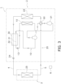
- a binary refrigeration cycle apparatus 1 employing an outdoor unit 2 is an apparatus used for cooling and heating an indoor space in an office building or the like by performing a vapor compression refrigeration cycle operation.
- the binary refrigeration cycle apparatus 1 includes a first cycle 10 and a second cycle 20.
- the binary refrigeration cycle apparatus 1 according to the present embodiment includes a binary refrigerant circuit including the vapor compression first cycle 10 and the vapor compression second cycle 20, and performs a binary refrigeration cycle.
- a combustible first refrigerant circulates.
- the first refrigerant has, for example, a critical point of 40°C or higher.
- the first refrigerant is, for example, a hydrocarbon refrigerant, R1234yf, R1234ze, R32, or the like, and is R290 in the present embodiment.
- the specific gravity of the first refrigerant is larger than the specific gravity of air.
- a non-combustible second refrigerant circulates.
- the second refrigerant has, for example, a critical point of less than 40°C.
- the second refrigerant includes, for example, carbon dioxide, and is a single refrigerant of carbon dioxide in the present embodiment.
- the first cycle 10 and the second cycle 20 are thermally connected via a cascade heat exchanger 30.
- the binary refrigeration cycle apparatus 1 includes the outdoor unit 2 and an indoor unit 3.
- the binary refrigeration cycle apparatus 1 is configured such that the outdoor unit 2 and the indoor unit 3 are connected to each other via connection pipes 4 and 5.
- the first cycle 10 constitutes a subcooling circuit during a cooling operation.
- the first cycle 10 includes a first compressor 11, a first heat exchanger 12, a first expansion mechanism 13, and the cascade heat exchanger 30.
- the first compressor 11 is configured to compress the first refrigerant and includes, for example, a scroll type or other positive displacement compressor whose operating capacity can be varied by controlling an inverter for a compressor motor.
- the first compressor 11 includes a first terminal 111.
- a power supply wire is connected to the first terminal 111.
- the first terminal 111 is a harness connection portion.
- the first heat exchanger 12 is configured to exchange heat between the first refrigerant and outdoor air.
- the first refrigerant acquires cooling energy or heating energy from the outdoor air.
- the first heat exchanger 12 includes, for example, a fin-and-tube heat exchanger including a large number of heat transfer tubes and fins.
- the first expansion mechanism 13 is configured to decompress the first refrigerant, and is, for example, an electric expansion valve.
- the cascade heat exchanger 30 is configured to perform heat exchange between the first refrigerant and the second refrigerant without mixing the refrigerants.
- the cascade heat exchanger 30 includes, for example, a plate heat exchanger.
- the cascade heat exchanger 30 includes a first flow path 31 belonging to the first cycle 10 and a second flow path 32 belonging to the second cycle 20.
- the first flow path 31 has a gas side connected to the first compressor 11, and a liquid side connected to the first expansion mechanism 13.
- the cascade heat exchanger 30 is intended to subcool the second refrigerant cooled by the second heat exchanger 23 and plays a role of assisting the second cycle 20.
- the second cycle 20 includes a second compressor 21, a switching mechanism 22, the second heat exchanger 23, the cascade heat exchanger 30, a second expansion mechanism 24, and a third heat exchanger 25.
- the second compressor 21 is configured to compress the second refrigerant and includes, for example, a scroll type or other positive-displacement compressor whose operating capacity can be varied by controlling an inverter for a compressor motor.
- the second compressor 21 includes a second terminal 211.
- a power supply wire is connected to the second terminal 211.
- the second terminal 211 is a harness connection portion.
- the switching mechanism 22 is configured to switch between a first state (see the solid lines in the switching mechanism 22 in FIG. 1 ) in which the second heat exchanger 23 functions as a radiator for the second refrigerant and the third heat exchanger 25 functions as an evaporator for the second refrigerant, and a second state (see the broken lines in the switching mechanism 22 in FIG. 1 ) in which the second heat exchanger 23 functions as an evaporator for the second refrigerant and the third heat exchanger 25 functions as a radiator for the second refrigerant.
- the switching mechanism 22 is, for example, a four-way switching valve.
- the switching mechanism 22 connects a discharge side of the second compressor 21 and a gas side of the second heat exchanger 23, and connects a suction side of the second compressor 21 and a gas side of the third heat exchanger 25.
- the switching mechanism 22 connects the discharge side of the second compressor 21 and the gas side of the third heat exchanger 25, and connects the suction side of the second compressor 21 and the gas side of the second heat exchanger 23.
- the second heat exchanger 23 is configured to exchange heat between the second refrigerant and outdoor air.
- the second refrigerant acquires cooling energy or heating energy from the outdoor air.
- the second heat exchanger 23 includes, for example, a fin-and-tube heat exchanger including a large number of heat transfer tubes and fins.
- the second cycle 20 includes the second flow path 32 of the cascade heat exchanger 30.
- the second flow path 32 has a gas side connected to the second heat exchanger 23, and a liquid side connected to the third heat exchanger 25.
- the second expansion mechanism 24 is configured to decompress the second refrigerant, and is, for example, an electric expansion valve.
- the third heat exchanger 25 is configured to exchange heat between the second refrigerant and indoor air, and includes, for example, a fin-and-tube heat exchanger including a large number of heat transfer tubes and fins.
- an up-down direction is a vertical direction.
- the outdoor unit 2 is disposed in a space different from a space in which the indoor unit 3 is disposed.
- the outdoor unit 2 is installed outdoors (on a roof of a building, near an outer wall surface of the building, or the like).
- the outdoor unit 2 includes the first cycle 10, a part of the second cycle 20, a casing 41, an electric component unit 420 including an electric component 42 and a substrate 43, a fan 44, a bell mouth 45, a partition plate 46, and a refrigerant leak sensor 47.
- the outdoor unit 2 includes the first compressor 11, the first heat exchanger 12, the first expansion mechanism 13, the second compressor 21, the switching mechanism 22, the second heat exchanger 23, the second expansion mechanism 24, and the cascade heat exchanger 30 which are illustrated in FIG. 2
- the casing 41, the electric component 42, the substrate 43, the fan 44, the bell mouth 45, the partition plate 46, and the refrigerant leak sensor 47 which are illustrated in FIG. 2 .
- the casing 41 accommodates the first compressor 11, the first heat exchanger 12, the first expansion mechanism 13, the second compressor 21, the switching mechanism 22, the second heat exchanger 23, the second expansion mechanism 24, the cascade heat exchanger 30, the electric component 42, the substrate 43, the fan 44, the bell mouth 45, the partition plate 46, and the refrigerant leak sensor 47.
- the casing 41 illustrated in FIG. 2 has a substantially rectangular parallelepiped shape. Specifically, the casing 41 includes a front panel 411, a top panel 412, a bottom plate 413, and a side plate 414.
- the front panel 411 is a plate-shaped member constituting a front surface of the casing 41.
- the front panel 411 is provided with a blow-out port.
- the blow-out port is an opening through which outdoor air taken into the casing 41 from outside is blown out of the casing 41.
- the top panel 412 is a plate-shaped member constituting an upper surface of the casing 41.
- the bottom plate 413 is a plate-shaped member constituting a lower surface of the casing 41.
- the top panel 412 and the bottom plate 413 face each other.
- the side plate 414 is a plate-shaped member constituting a side surface of the casing 41. A lower portion of the side plate 414 is fixed to the bottom plate 413.
- the casing 41 is provided with an opening 415 for allowing outdoor air to flow through a communication hole 461 of the partition plate 46 described later.
- the opening 415 is formed in the side plate 414 that defines a second chamber S2 described later.
- the opening 415 is not required to be formed in the side plate 414, and can be provided in any member that partitions the second chamber S2 and the outside of the casing 41.
- the electric component 42 (electric part) is mounted on the substrate 43.
- the electric component 42 controls control targets such as the first compressor 11, the second compressor 21, the first expansion mechanism 13, the switching mechanism 22, and the second expansion mechanism 24.
- the electric component 42 includes, for example, an element to be cooled such as a power element, a reactor, a capacitor, a wire connection portion, and the like.
- the electric component 42 is attached to the substrate 43.
- the substrate 43 is, for example, a printed circuit board.
- the substrate 43 extends in the up-down direction.
- a plurality of electric components 42 is attached to the substrate 43.
- the fan 44 causes air to flow to the first heat exchanger 12 and the second heat exchanger 23.
- the fan 44 causes outdoor air to flow to both the first heat exchanger 12 and the second heat exchanger 23.
- the fan 44 guides the outdoor air to the first heat exchanger 12 and the second heat exchanger 23 to generate an air flow that exchanges heat with the first refrigerant flowing through the first heat exchanger 12, exchanges heat with the second refrigerant flowing through the second heat exchanger 23, and then, is discharged to outdoors.
- the fan 44 is driven by a fan motor. Note that a fan that flows air to the first heat exchanger 12 and a fan that flows air to the second heat exchanger 23 may be separately provided.
- the bell mouth 45 is disposed on a blow-out side of the fan 44.
- the bell mouth 45 has a cylindrical portion surrounding the fan 44.
- the cylindrical portion forms an opening.
- the fan 44 is disposed inside the cylindrical portion.
- the fan 44 and the bell mouth 45 overlap the first heat exchanger 12 and the second heat exchanger 23 when viewed from the front.
- the bell mouth 45 faces the blow-out port (not illustrated) formed in the front panel 411 of the casing 41.
- the refrigerant leak sensor 47 detects a leak of the first refrigerant.
- the refrigerant leak sensor 47 is disposed in a lower part of the casing 41.
- the refrigerant leak sensor 47 may further detect a leak of the second refrigerant.
- the partition plate 46 is a plate-shaped member extending in the up-down direction. A lower portion of the partition plate 46 is fixed to the bottom plate 413 of the casing 41.
- the partition plate 46 partitions the inside of casing 41 into the first chamber S1 and the second chamber S2.
- Each of the first chamber S1 and the second chamber S2 is a space defined by the front panel 411, the top panel 412, the bottom plate 413, the side plate 414, and the partition plate 46 of the casing 41.
- the first chamber S1 is an air blowing chamber, and is an air guiding path through which air sucked from a suction port of the outdoor unit 2 flows to the blow-out port.
- the second chamber S2 is a machine chamber.
- the first heat exchanger 12, the second heat exchanger 23, the fan 44, and the bell mouth 45 are disposed in the first chamber S1.
- the first compressor 11, the second compressor 21, the switching mechanism 22, the first expansion mechanism 13, the second expansion mechanism 24, the electric component unit 420 including the electric component 42 and the substrate 43, and the refrigerant leak sensor 47 are disposed.
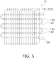
- the partition plate 46 is provided with the communication hole 461. As illustrated in FIG. 5 , the communication hole 461 is provided above a first brazed portion 121 disposed uppermost among a plurality of brazed portions 120 of the first heat exchanger 12.
- the brazed portion 120 is a portion where the first refrigerant may leak from the first heat exchanger 12 in the first chamber S1.
- the brazed portion 120 according to the present embodiment is a joint portion between heat transfer tubes constituting the first heat exchanger 12, a joint portion between a heat transfer tube and a fin, or the like.
- the heat transfer tube includes a U-shaped tube, a branch tube, and the like.
- the plurality of brazed portions 120 are joint portions between a hairpin-shaped tube and a U-shaped tube or a branch tube.
- a height position of the communication hole 461 in the up-down direction is indicated by P1
- a height position of the first brazed portion 121 in the up-down direction is indicated by P2.
- the height position P1 of the communication hole 461 in the up-down direction is a lowermost end of the communication hole 461. Therefore, the height position P1 of the lowermost end of the communication hole 461 is higher than the height position of the first brazed portion 121 in the up-down direction.
- the communication hole 461 is a hole for guiding outdoor air flowing into the second chamber S2 from the opening 415 of the casing 41 to the first chamber S1.
- the communication hole 461 according to the present embodiment is a hole for guiding air around the electric component unit 420 including the electric component 42 and the substrate 43 to the fan 44.
- the communication hole 461 is a hole for guiding outdoor air around the electric component unit 420 including the electric components 42 and the substrate 43 in the second chamber S2 to the fan 44 in the first chamber S 1.
- the communication hole 461 is located above an upper end of the first heat exchanger 12.
- the height position P1 of the communication hole 461 overlaps with the second heat exchanger 23.
- the communication hole 461 is located above a lower end 451 of the cylindrical portion of the bell mouth 45.
- the communication hole 461 is located above the first terminal 111 of the first compressor 11 and the second terminal 211 of the second compressor 21.
- the communication hole 461 is located above a lower end 431 of the electric component unit 420 (here, the substrate 43).
- the height position P1 of the lowermost end of the communication hole 461 is located above the electric component 42 disposed lowermost among the plurality of electric components 42.
- the first heat exchanger 12 is located below the second heat exchanger 23. In other words, at least a part of the first heat exchanger 12 is located below the second heat exchanger 23.
- the entire first heat exchanger 12 may be located below the second heat exchanger 23, and a part of the first heat exchanger 12 may be located below the second heat exchanger 23.
- first heat exchanger 12 and the second heat exchanger 23 may be separated or may be integrated.
- size of the first heat exchanger 12 may be about the same as or may be smaller in a height direction in the up-down direction than the size of the second heat exchanger 23.
- the electric component unit 420 including the electric component 42 and the substrate 43 is disposed above the first compressor 11 and the second compressor 21.
- the lower end 431 of the electric component unit 420 (here, the substrate 43) is located above the lower end 451 of the cylindrical portion of the bell mouth 45.
- a height position of the lower end 431 of the electric component unit 420 (here, the substrate 43 to which the electric component 42 is attached) in the up-down direction is higher than the opening lower end 451 of the bell mouth 45 disposed on the blow-out side of the fan 44.
- the electric component 42 located lowermost among the plurality of electric components 42 is located above the lower end 451 of the cylindrical portion of the bell mouth 45.
- the lower end 431 of the electric component unit 420 (here, the substrate 43) is located above the first brazed portion 121.
- a height position of the electric component unit 420 (here, the substrate 43 to which the electric component 42 is attached) is higher than the height position P1 of the first brazed portion 121.
- the electric component 42 located lowermost among the plurality of electric components 42 is located above the first brazed portion 121.
- the first terminal 111 of the first compressor 11 and the second terminal 211 of the second compressor 21 are located above the lower end 451 of the cylindrical portion of the bell mouth 45.
- a lower end of the first terminal 111 of the first compressor 11 and a lower end of the second terminal 211 of the second compressor 21 are located above the lower end 451 of the cylindrical portion of the bell mouth 45.
- the indoor unit 3 is installed indoors (inside the building). As described above, the indoor unit 3 is connected to the outdoor unit 2 via the connection pipes 4 and 5, and constitutes a part of the second cycle 20.
- the indoor unit 3 includes the third heat exchanger 25.
- the indoor unit 3 is installed by being embedded in or being suspended from a ceiling on an indoor space of a building or the like, or by being hung on a wall surface in the indoor space, or the like.
- connection pipes 4 and 5 are refrigerant pipes constructed on the site when the binary refrigeration cycle apparatus 1 is installed at an installation location such as a building.
- One end of the liquid-side connection pipe 4 is connected to a liquid-side end of the outdoor unit 2, and the other end of the connection pipe 4 is connected to a liquid-side end of the third heat exchanger 25 of the indoor unit 3.
- One end of the gas-side connection pipe 5 is connected to a gas-side end of the outdoor unit 2, and the other end of the connection pipe 5 is connected to a gas-side end of the third heat exchanger 25 of the indoor unit 3.
- the constituent devices of the outdoor unit 2 and the indoor unit 3 are controlled by the control unit 6.
- the control unit 6 is configured by communicably connecting the electric component 42, the substrate 43, and the like provided in the outdoor unit 2, a control board and the like (not illustrated) provided in the indoor unit 3, and the like.
- the control unit 6 is illustrated at a position apart from the outdoor unit 2, the indoor unit 3, and the like for convenience.
- the control unit 6 controls the constituent devices of the binary refrigeration cycle apparatus 1 (here, the outdoor unit 2 and the indoor unit 3). In other words, the control unit 6 controls the operation of the entire binary refrigeration cycle apparatus 1.
- the control unit 6 is implemented by a computer.
- the control unit 6 includes a control calculation device and a storage device.
- a processor such as a CPU or a GPU can be used for the control calculation device.
- the control calculation device reads a program stored in the storage device, and executes predetermined image processing and calculation processing in accordance with this program. Furthermore, the control calculation device can write a calculation result to the storage device and read information stored in the storage device in accordance with the program.
- the binary refrigeration cycle apparatus 1 can perform a cooling operation for cooling indoor air and a heating operation for heating indoor air for indoor air conditioning. In the cooling operation and the heating operation, the operation of the binary refrigeration cycle apparatus 1 is controlled by the control unit 6.
- the switching mechanism 22 is switched to the first state (the switching mechanism 22 is in a state indicated by the solid lines) such that the second heat exchanger 23 functions as a radiator for the second refrigerant and the third heat exchanger 25 functions as an evaporator for the second refrigerant.
- the second refrigerant discharged from the second compressor 21 is sent to the second heat exchanger 23 through the switching mechanism 22.
- the second refrigerant sent to the second heat exchanger 23 exchanges heat with the outdoor air supplied by the fan 44 and is cooled to radiate heat.
- the second refrigerant having radiated heat in the second heat exchanger 23 is sent to the second flow path 32 of the cascade heat exchanger 30.
- the second refrigerant sent to the second flow path 32 exchanges heat with the first refrigerant flowing through the first flow path 31 in the cascade heat exchanger 30 to be further cooled.
- the second refrigerant further cooled by the cascade heat exchanger 30 is decompressed by the second expansion mechanism 24 and then flows out of the outdoor unit 2.
- the second refrigerant having flowed out of the outdoor unit 2 flows into the indoor unit 3 via the liquid-side connection pipe 4.
- the second refrigerant is sent to the third heat exchanger 25.
- the second refrigerant sent to the third heat exchanger 25 exchanges heat with indoor air and is heated to evaporate.
- the second refrigerant having evaporated in the third heat exchanger 25 flows out of the indoor unit 3.
- the second refrigerant having flowed out of the indoor unit 3 flows into the outdoor unit 2 via the gas-side connection pipe 5.
- the second refrigerant is again sucked into the second compressor 21 through the switching mechanism 22.
- the first refrigerant discharged from the first compressor 11 is sent to the first heat exchanger 12.
- the first refrigerant sent to the first heat exchanger 12 exchanges heat with the outdoor air supplied by the fan 44 and is cooled to be condensed.
- the first refrigerant condensed in the first heat exchanger 12 is decompressed by the first expansion mechanism 13 and then sent to the first flow path 31 of the cascade heat exchanger 30.
- the first refrigerant sent to the first flow path 31 exchanges heat with the second refrigerant flowing through the second flow path 32 in the cascade heat exchanger 30 and is heated to evaporate.
- the first refrigerant having evaporated in the cascade heat exchanger 30 is sucked into the first compressor 11 again.
- the switching mechanism 22 is switched to the second state (the switching mechanism 22 is in a state indicated by the broken lines) such that the second heat exchanger 23 functions as an evaporator for the second refrigerant and the third heat exchanger 25 functions as a radiator for the second refrigerant.
- the first compressor 11 is not activated, and the first refrigerant in the first cycle 10 is not circulated.
- the second refrigerant discharged from the second compressor 21 flows out of the outdoor unit 2 through the switching mechanism 22.
- the refrigerant having flowed out of the outdoor unit 2 flows into the indoor unit 3 via the gas-side connection pipe 5.
- the second refrigerant is sent to the third heat exchanger 25.
- the second refrigerant sent to the third heat exchanger 25 exchanges heat with indoor air and is cooled to radiate heat.
- the second refrigerant having radiated heat in the third heat exchanger 25 flows out of the indoor unit 3.
- the second refrigerant having flowed out of the indoor unit 3 flows into the outdoor unit 2 via the liquid-side connection pipe 4.
- the second refrigerant is sent to the second heat exchanger 23 through the second expansion mechanism 24 and the second flow path 32 of the cascade heat exchanger 30.
- the second refrigerant sent to the second heat exchanger 23 exchanges heat with the outdoor air supplied by the fan 44 and is heated to evaporate.
- the second refrigerant having evaporated in the second heat exchanger 23 is again sucked into the second compressor 21 through the switching mechanism 22.
- the outdoor air flows from the opening 415 of the side plate 414 of the casing 41 to the second chamber S2, further passes through the communication hole 461 of the partition plate 46, and flows to the first chamber S1.
- the outdoor air having passed through the communication hole 461 flows to the fan 44. While the fan 44 is being driven, the outdoor air flows from the first chamber S1 to outside of the casing 41.
- the second refrigerant which is non-combustible has a lower risk in leakage.
- the first refrigerant which is combustible flows into the electric component unit 420 (in particular, the electric component 42) serving as an ignition source, there is a possibility that the first refrigerant is ignited.
- the first refrigerant is highly likely to leak from the plurality of brazed portions of the first heat exchanger 12.
- the communication hole 461 is located above the first brazed portion 121 located uppermost among the plurality of brazed portions 120, even if the first refrigerant which is heavier than air leaks, the first refrigerant is prevented from flowing above the communication hole 461.
- the first refrigerant having leaked is prevented from flowing into the second chamber S2 by the outdoor air flowing from the communication hole 461 to the second chamber S2.
- the electric component unit 420 (here, the electric component 42) is located in an upper part as in the present embodiment, since the communication hole 461 is located in the upper part in the casing 41, the outdoor air flowing into the second chamber S2 passes around the electric component unit 420 (here, the electric component 42). Therefore, the outdoor air around the electric component unit 420 (here, the electric component 42) can be promoted to flow to the first chamber S1. Accordingly, the leaked first refrigerant is prevented from flowing around the electric component 42.
- the first refrigerant above the lower end 451 of the cylindrical portion of the bell mouth 45 is discharged to outside of the casing 41 through the cylindrical portion of the bell mouth 45 and the blow-out port of the casing 41.
- the outdoor unit 2 as an air conditioning unit according to the present embodiment includes the electric component unit 420, the first heat exchanger 12, the second heat exchanger 23, the fan 44, the casing 41, and the partition plate 46.
- the first heat exchanger 12 exchanges heat between the combustible first refrigerant and air.
- the second heat exchanger 23 exchanges heat between the non-combustible second refrigerant and air.
- the fan 44 causes air to flow to the first heat exchanger 12 and the second heat exchanger 23.
- the casing 41 accommodates the electric component unit 420, the first heat exchanger 12, the second heat exchanger 23, and the fan 44.
- the partition plate 46 partitions the inside of the casing 41 into the first chamber S1 in which the first heat exchanger 12, the second heat exchanger 23, and the fan 44 are disposed, and the second chamber S2 in which the electric component unit 420 is disposed.
- the partition plate 46 is provided with the communication hole 461 that communicates the first chamber S1 and the second chamber S2 above the first brazed portion 121 located uppermost among the plurality of brazed portions 120 of the first heat exchanger 12.
- the communication hole 461 provided in the partition plate 46 and the fan 44 disposed in the first chamber S1 allow air to flow from the second chamber S2 in which the electric component unit 420 is disposed to the first chamber S1 in which the first heat exchanger 12 through which the first refrigerant flows is disposed. Since the communication hole 461 is provided at the position P1 higher than the first brazed portion 121 at the highest position P2 in the first heat exchanger 12 through which the combustible first refrigerant flows, even if the first refrigerant leaks in the first chamber S1, the first refrigerant can be prevented from flowing above the communication hole 461. Therefore, the possibility of ignition with the electric component unit 420 in the second chamber S2 as an ignition source can be reduced.
- the air conditioning unit is particularly useful for a highly flammable (A3) refrigerant such as R290.
- the outdoor unit 2 serving as the air conditioning unit according to the present embodiment is the outdoor unit 2 according to (4-1), in which the communication hole 461 is a hole that guides air around the electric component unit 420 to the fan.
- the air around the electric component unit 420 serving as an ignition source is guided to the first chamber S1 through the communication hole 461, even if the first refrigerant leaks, the first refrigerant can be suppressed from flowing around the electric component unit 420.
- the outdoor unit 2 as an air conditioning unit according to the present embodiment is the outdoor unit 2 according to (4-1) or (4-2) and further includes the bell mouth 45.
- the bell mouth 45 is disposed in the first chamber S1 and has the cylindrical portion surrounding the fan 44.
- the lower end 431 of the electric component unit 420 is located above the lower end 451 of the cylindrical portion.
- the fan 44 is disposed inside the cylindrical portion of the bell mouth 45.
- the first refrigerant is heavier than air. Therefore, even if the first refrigerant leaks, the first refrigerant stays below the lower end 451 of the cylindrical portion.
- the lower end 431 of the electric component unit 420 (specifically, the substrate 43 to which the electric component 42 is attached) is located above the lower end 451 of the cylindrical portion, even if there is a gap between the lower end of the partition plate 46 and the bottom plate 413 of the casing 41 and the first refrigerant flows into the second chamber S2, the first refrigerant accumulated below can be prevented from reaching a height level of the electric component unit 420.
- the outdoor unit 2 serving as an air conditioning unit according to the present embodiment is the outdoor unit 2 according to any of (4-1) to (4-3), in which the electric component unit 420 is located above the first brazed portion 121.
- the first refrigerant stays below the first brazed portion 121.
- the electric component unit 420 is located above the first brazed portion 121, the first refrigerant can be further prevented from flowing to the electric component.
- the outdoor unit 2 serving as an air conditioning unit according to the present embodiment is the outdoor unit 2 according to any of (4-1) to (4-4), in which the first heat exchanger 12 is located below the second heat exchanger 23.
- the first heat exchanger 12 through which the combustible refrigerant flows is disposed below the second heat exchanger 23 through which the non-combustible refrigerant flows. Accordingly, even if the first refrigerant leaks, the first refrigerant is likely to stay below, and a distance between the communication hole 461 and the first brazed portion 121 can be secured. Therefore, the outdoor unit 2 that prevents the first refrigerant from flowing to the electric component unit 420 can be easily achieved.
- the outdoor unit 2 as an air conditioning unit according to the present embodiment is the outdoor unit 2 according to any of (4-1) to (4-5) and further includes the first compressor 11, the second compressor 21, and the bell mouth 45.
- the first compressor 11 is disposed in the second chamber S2 and compresses the first refrigerant.
- the second compressor 21 is disposed in the second chamber S2 and compresses the second refrigerant.
- the bell mouth 45 is disposed in the first chamber S1 and has the cylindrical portion surrounding the fan 44.
- the first terminal 111 of the first compressor 11 and the second terminal 211 of the second compressor 21 are located above the lower end 451 of the cylindrical portion.
- the first refrigerant stays below the lower end 451 of the cylindrical portion of the bell mouth 45.
- the first terminal 111 and the second terminal 211 are located above the lower end 451 of the cylindrical portion, the possibility of ignition with the first terminal 111 and the second terminal 211 of the second chamber S2 as ignition sources can be reduced.
- the outdoor unit 2 as an air conditioning unit according to the present embodiment is the outdoor unit 2 according to any of (4-1) to (4-5), in which the second refrigerant includes carbon dioxide.
- the outdoor unit 2 Since the carbon dioxide refrigerant has a low global warming potential (GWP), the outdoor unit 2 which contributes to reduction in global warming can be achieved.
- GWP global warming potential
- the air conditioning unit is the outdoor unit 2 of the binary refrigeration cycle apparatus 1, but the present disclosure is not limited to this configuration.
- the air conditioning unit of the present disclosure may be an indoor unit or a cascade unit.
- the binary refrigeration cycle apparatus 1 in which one indoor unit 3 is connected to one outdoor unit 2 has been described as an example.
- the present disclosure is not limited to this example.
- a plurality of indoor units is connected to one outdoor unit.
- the air conditioning unit of the binary refrigeration cycle apparatus 1 that performs the cooling operation and the heating operation has been described as an example.
- the binary refrigeration cycle apparatus including the air conditioning unit of the present disclosure may further perform a dehumidifying operation.
- the binary refrigeration cycle apparatus including the air conditioning unit of the present disclosure may be an air conditioner dedicated to cooling.
- Patent Literature 1 JP 5430604 B2
Landscapes
- Engineering & Computer Science (AREA)
- Mechanical Engineering (AREA)
- General Engineering & Computer Science (AREA)
- Physics & Mathematics (AREA)
- Thermal Sciences (AREA)
- Chemical & Material Sciences (AREA)
- Combustion & Propulsion (AREA)
- Other Air-Conditioning Systems (AREA)
Applications Claiming Priority (2)
| Application Number | Priority Date | Filing Date | Title |
|---|---|---|---|
| JP2022198099A JP7518418B2 (ja) | 2022-12-12 | 2022-12-12 | 空調ユニット |
| PCT/JP2023/041728 WO2024127924A1 (ja) | 2022-12-12 | 2023-11-21 | 空調ユニット |
Publications (3)
| Publication Number | Publication Date |
|---|---|
| EP4407243A1 true EP4407243A1 (de) | 2024-07-31 |
| EP4407243A4 EP4407243A4 (de) | 2025-02-26 |
| EP4407243B1 EP4407243B1 (de) | 2025-12-31 |
Family
ID=90481893
Family Applications (1)
| Application Number | Title | Priority Date | Filing Date |
|---|---|---|---|
| EP23864106.2A Active EP4407243B1 (de) | 2022-12-12 | 2023-11-21 | Klimaanlage |
Country Status (5)
| Country | Link |
|---|---|
| US (1) | US20250290676A1 (de) |
| EP (1) | EP4407243B1 (de) |
| JP (1) | JP7518418B2 (de) |
| CN (1) | CN120202382A (de) |
| WO (1) | WO2024127924A1 (de) |
Families Citing this family (2)
| Publication number | Priority date | Publication date | Assignee | Title |
|---|---|---|---|---|
| JP7656242B2 (ja) * | 2023-07-03 | 2025-04-03 | ダイキン工業株式会社 | 冷凍装置 |
| JP2026007573A (ja) * | 2024-07-03 | 2026-01-16 | ダイキン工業株式会社 | 冷凍装置 |
Family Cites Families (8)
| Publication number | Priority date | Publication date | Assignee | Title |
|---|---|---|---|---|
| EP1959204B1 (de) * | 2007-02-13 | 2011-08-03 | Mitsubishi Electric Corporation | Luft-/Wasserwärmeaustauschervorrichtung |
| JP4858605B2 (ja) | 2009-12-11 | 2012-01-18 | パナソニック株式会社 | 密閉型電動圧縮機 |
| JP5709575B2 (ja) | 2011-02-21 | 2015-04-30 | 三菱電機株式会社 | 冷凍装置 |
| JP5430604B2 (ja) | 2011-04-08 | 2014-03-05 | 三菱電機株式会社 | 二元冷凍装置 |
| JP5673612B2 (ja) | 2012-06-27 | 2015-02-18 | 三菱電機株式会社 | 冷凍サイクル装置 |
| KR102264725B1 (ko) | 2014-05-22 | 2021-06-11 | 엘지전자 주식회사 | 히트 펌프 |
| WO2022013976A1 (ja) | 2020-07-15 | 2022-01-20 | 三菱電機株式会社 | 冷凍装置の室外機およびそれを備える冷凍装置 |
| KR102913913B1 (ko) * | 2020-07-20 | 2026-01-15 | 엘지전자 주식회사 | 히트펌프 |
-
2022
- 2022-12-12 JP JP2022198099A patent/JP7518418B2/ja active Active
-
2023
- 2023-11-21 EP EP23864106.2A patent/EP4407243B1/de active Active
- 2023-11-21 CN CN202380079292.XA patent/CN120202382A/zh active Pending
- 2023-11-21 WO PCT/JP2023/041728 patent/WO2024127924A1/ja not_active Ceased
-
2025
- 2025-06-02 US US19/225,296 patent/US20250290676A1/en active Pending
Also Published As
| Publication number | Publication date |
|---|---|
| EP4407243B1 (de) | 2025-12-31 |
| US20250290676A1 (en) | 2025-09-18 |
| CN120202382A (zh) | 2025-06-24 |
| JP2024083974A (ja) | 2024-06-24 |
| EP4407243A4 (de) | 2025-02-26 |
| JP7518418B2 (ja) | 2024-07-18 |
| WO2024127924A1 (ja) | 2024-06-20 |
Similar Documents
| Publication | Publication Date | Title |
|---|---|---|
| US20250290676A1 (en) | Air conditioning unit | |
| EP3372923B1 (de) | Klimatisierungsvorrichtung | |
| CN203478432U (zh) | 冷冻循环装置 | |
| US20210348820A1 (en) | Heat load processing system | |
| US20220214085A1 (en) | Evaporator and refrigeration cycle apparatus including the same | |
| US20220404038A1 (en) | Air conditioning system | |
| EP2472200A1 (de) | Klimaanlage | |
| EP3112768B1 (de) | Klimaanlage | |
| JP2015087042A (ja) | 空気調和装置 | |
| EP3121536A1 (de) | Verdichter und kühlkreisvorrichtung damit | |
| CN113834248A (zh) | 空调机 | |
| WO2020189586A1 (ja) | 冷凍サイクル装置 | |
| EP3128258A1 (de) | Akkumulator und kühlkreisvorrichtung | |
| JPWO2019130383A1 (ja) | 空気調和装置 | |
| US12467661B2 (en) | Cascade unit and refrigeration cycle apparatus | |
| CN106104169A (zh) | 制冷循环装置 | |
| EP4553412A1 (de) | Kältekreislaufvorrichtung | |
| EP3136023A1 (de) | Drosselvorrichtung und kühlkreisvorrichtung damit | |
| EP4513108A1 (de) | Wärmequelleneinheit und kühlvorrichtung | |
| JPWO2020183607A1 (ja) | 室内機 | |
| JPWO2019123631A1 (ja) | 空気調和装置 | |
| JP2025058503A (ja) | 冷凍サイクル装置 | |
| JP2024076803A (ja) | 空気調和装置 |
Legal Events
| Date | Code | Title | Description |
|---|---|---|---|
| STAA | Information on the status of an ep patent application or granted ep patent |
Free format text: STATUS: UNKNOWN |
|
| STAA | Information on the status of an ep patent application or granted ep patent |
Free format text: STATUS: THE INTERNATIONAL PUBLICATION HAS BEEN MADE |
|
| PUAI | Public reference made under article 153(3) epc to a published international application that has entered the european phase |
Free format text: ORIGINAL CODE: 0009012 |
|
| STAA | Information on the status of an ep patent application or granted ep patent |
Free format text: STATUS: REQUEST FOR EXAMINATION WAS MADE |
|
| 17P | Request for examination filed |
Effective date: 20240319 |
|
| AK | Designated contracting states |
Kind code of ref document: A1 Designated state(s): AL AT BE BG CH CY CZ DE DK EE ES FI FR GB GR HR HU IE IS IT LI LT LU LV MC ME MK MT NL NO PL PT RO RS SE SI SK SM TR |
|
| P01 | Opt-out of the competence of the unified patent court (upc) registered |
Free format text: CASE NUMBER: APP_976/2025 Effective date: 20250108 |
|
| A4 | Supplementary search report drawn up and despatched |
Effective date: 20250123 |
|
| RIC1 | Information provided on ipc code assigned before grant |
Ipc: F25B 49/02 20060101ALI20250117BHEP Ipc: F25B 7/00 20060101ALI20250117BHEP Ipc: F25B 1/00 20060101ALI20250117BHEP Ipc: F24F 1/48 20110101ALI20250117BHEP Ipc: F24F 1/46 20110101ALI20250117BHEP Ipc: F24F 1/24 20110101AFI20250117BHEP |
|
| GRAP | Despatch of communication of intention to grant a patent |
Free format text: ORIGINAL CODE: EPIDOSNIGR1 |
|
| STAA | Information on the status of an ep patent application or granted ep patent |
Free format text: STATUS: GRANT OF PATENT IS INTENDED |
|
| DAV | Request for validation of the european patent (deleted) | ||
| DAX | Request for extension of the european patent (deleted) | ||
| INTG | Intention to grant announced |
Effective date: 20250911 |
|
| GRAS | Grant fee paid |
Free format text: ORIGINAL CODE: EPIDOSNIGR3 |
|
| GRAA | (expected) grant |
Free format text: ORIGINAL CODE: 0009210 |
|
| STAA | Information on the status of an ep patent application or granted ep patent |
Free format text: STATUS: THE PATENT HAS BEEN GRANTED |
|
| AK | Designated contracting states |
Kind code of ref document: B1 Designated state(s): AL AT BE BG CH CY CZ DE DK EE ES FI FR GB GR HR HU IE IS IT LI LT LU LV MC ME MK MT NL NO PL PT RO RS SE SI SK SM TR |
|
| REG | Reference to a national code |
Ref country code: CH Ref legal event code: F10 Free format text: ST27 STATUS EVENT CODE: U-0-0-F10-F00 (AS PROVIDED BY THE NATIONAL OFFICE) Effective date: 20251231 Ref country code: GB Ref legal event code: FG4D |
|
| REG | Reference to a national code |
Ref country code: DE Ref legal event code: R096 Ref document number: 602023010557 Country of ref document: DE |