EP4407204A1 - Shaft connection - Google Patents
Shaft connection Download PDFInfo
- Publication number
- EP4407204A1 EP4407204A1 EP24153377.7A EP24153377A EP4407204A1 EP 4407204 A1 EP4407204 A1 EP 4407204A1 EP 24153377 A EP24153377 A EP 24153377A EP 4407204 A1 EP4407204 A1 EP 4407204A1
- Authority
- EP
- European Patent Office
- Prior art keywords
- shaft
- spring element
- spring
- connection
- rotation
- Prior art date
- Legal status (The legal status is an assumption and is not a legal conclusion. Google has not performed a legal analysis and makes no representation as to the accuracy of the status listed.)
- Pending
Links
Images


Classifications
-
- F—MECHANICAL ENGINEERING; LIGHTING; HEATING; WEAPONS; BLASTING
- F16—ENGINEERING ELEMENTS AND UNITS; GENERAL MEASURES FOR PRODUCING AND MAINTAINING EFFECTIVE FUNCTIONING OF MACHINES OR INSTALLATIONS; THERMAL INSULATION IN GENERAL
- F16D—COUPLINGS FOR TRANSMITTING ROTATION; CLUTCHES; BRAKES
- F16D3/00—Yielding couplings, i.e. with means permitting movement between the connected parts during the drive
- F16D3/02—Yielding couplings, i.e. with means permitting movement between the connected parts during the drive adapted to specific functions
- F16D3/06—Yielding couplings, i.e. with means permitting movement between the connected parts during the drive adapted to specific functions specially adapted to allow axial displacement
-
- B—PERFORMING OPERATIONS; TRANSPORTING
- B64—AIRCRAFT; AVIATION; COSMONAUTICS
- B64C—AEROPLANES; HELICOPTERS
- B64C13/00—Control systems or transmitting systems for actuating flying-control surfaces, lift-increasing flaps, air brakes, or spoilers
- B64C13/24—Transmitting means
- B64C13/26—Transmitting means without power amplification or where power amplification is irrelevant
- B64C13/28—Transmitting means without power amplification or where power amplification is irrelevant mechanical
- B64C13/30—Transmitting means without power amplification or where power amplification is irrelevant mechanical using cable, chain, or rod mechanisms
-
- F—MECHANICAL ENGINEERING; LIGHTING; HEATING; WEAPONS; BLASTING
- F16—ENGINEERING ELEMENTS AND UNITS; GENERAL MEASURES FOR PRODUCING AND MAINTAINING EFFECTIVE FUNCTIONING OF MACHINES OR INSTALLATIONS; THERMAL INSULATION IN GENERAL
- F16D—COUPLINGS FOR TRANSMITTING ROTATION; CLUTCHES; BRAKES
- F16D11/00—Clutches in which the members have interengaging parts
- F16D11/14—Clutches in which the members have interengaging parts with clutching members movable only axially
-
- F—MECHANICAL ENGINEERING; LIGHTING; HEATING; WEAPONS; BLASTING
- F16—ENGINEERING ELEMENTS AND UNITS; GENERAL MEASURES FOR PRODUCING AND MAINTAINING EFFECTIVE FUNCTIONING OF MACHINES OR INSTALLATIONS; THERMAL INSULATION IN GENERAL
- F16D—COUPLINGS FOR TRANSMITTING ROTATION; CLUTCHES; BRAKES
- F16D3/00—Yielding couplings, i.e. with means permitting movement between the connected parts during the drive
- F16D3/50—Yielding couplings, i.e. with means permitting movement between the connected parts during the drive with the coupling parts connected by one or more intermediate members
- F16D3/60—Yielding couplings, i.e. with means permitting movement between the connected parts during the drive with the coupling parts connected by one or more intermediate members comprising pushing or pulling links attached to both parts
- F16D3/62—Yielding couplings, i.e. with means permitting movement between the connected parts during the drive with the coupling parts connected by one or more intermediate members comprising pushing or pulling links attached to both parts the links or their attachments being elastic
-
- F—MECHANICAL ENGINEERING; LIGHTING; HEATING; WEAPONS; BLASTING
- F16—ENGINEERING ELEMENTS AND UNITS; GENERAL MEASURES FOR PRODUCING AND MAINTAINING EFFECTIVE FUNCTIONING OF MACHINES OR INSTALLATIONS; THERMAL INSULATION IN GENERAL
- F16D—COUPLINGS FOR TRANSMITTING ROTATION; CLUTCHES; BRAKES
- F16D3/00—Yielding couplings, i.e. with means permitting movement between the connected parts during the drive
- F16D3/50—Yielding couplings, i.e. with means permitting movement between the connected parts during the drive with the coupling parts connected by one or more intermediate members
- F16D3/72—Yielding couplings, i.e. with means permitting movement between the connected parts during the drive with the coupling parts connected by one or more intermediate members with axially-spaced attachments to the coupling parts
Definitions
- the disclosure relates to a shaft connection, a coupling and a use of a shaft connection or a coupling.
- Shaft connections or couplings are known from the prior art, where two shafts are connected via a spring.
- the spring can cause a restoring force in the axial direction on one of the two shafts relative to another of the two shafts.
- the WO 2020/128403 A1 a force generating device for an aircraft control stick, wherein an actuator can be moved by an electromagnet and wherein a spring exerts a return force on the actuator.
- shaft connections or couplings known from the prior art have restrictions, in particular with regard to a torsional rigidity of shaft connections or with regard to an axial lifting force provided by the shaft connection.
- the object of the disclosure is to provide a shaft connection, a coupling and a use of a shaft connection or a coupling which are improved compared to the prior art.
- a shaft connection should be provided which has a high torsional rigidity or requires a low axial lifting force.
- a shaft connection comprises a first shaft rotatable about an axis of rotation, a second shaft arranged coaxially to the first shaft and axially movable relative to the first shaft, and at least one pair of spring elements each having a first spring element and a second spring element, wherein the first spring element and the second spring element are each fastened to the first shaft and to the second shaft, and wherein the first spring element and the second spring element are arranged axially offset from one another.
- a coupling comprises a shaft connection according to one of the embodiments described herein, and a rotor shaft arranged coaxially to the first shaft and the second shaft, wherein the coupling is designed to couple the first shaft and the second shaft to the rotor shaft in order to move the second shaft axially in the direction of the rotor shaft.
- the shaft connection comprises a first shaft.
- the first shaft of the shaft connection is rotatable about an axis of rotation.
- the terms “axial”, “coaxial”, “radial” and “in the circumferential direction” refer here in particular to the axis of rotation.
- An axial direction is to be understood in particular as a direction of the axis of rotation.
- the shaft connection comprises a second shaft.
- the first shaft and the second shaft are arranged coaxially.
- the first shaft is an output shaft.
- the second shaft is typically a drive shaft.
- the first shaft can be a drive shaft and the second shaft an output shaft.
- the first shaft or the second shaft is designed as a hollow shaft, in particular circular.
- the first shaft or the second shaft is designed as a solid shaft.
- the first shaft and the second shaft are made of metal.
- the shaft connection comprises at least one pair of spring elements.
- a first spring element and a second spring element form a pair of spring elements.
- the first spring element and the second spring element are identical.
- the first shaft and the second shaft are connected to one another via the at least one pair of spring elements, in particular connected to one another in a rotationally fixed manner.
- first spring element and the second spring element of a spring element pair are each fastened to the first shaft and to the second shaft, in particular via force-fitting or form-fitting fastening means such as screws or rivets.
- first shaft and the second shaft can have stepped flat surfaces for fastening the at least one spring element pair.
- first spring element and the second spring element of the at least one spring element pair are arranged axially offset from one another.
- first spring element and the second spring element are arranged axially spaced from one another.
- An axial distance between a spring element of a spring element pair and the first shaft or the second shaft can be provided, for example, by an axial spacer which is arranged at the fastening position of the spring element between the spring element and the first shaft or the second shaft. Spacers can be designed as part of fastening means for fastening the spring elements to the first shaft and to the second shaft.
- An axial distance between the spring elements of a spring element pair can be provided by different distances of the spring elements to the first shaft or the second shaft. Different axial distances of the spring elements to the first shaft or the second shaft can be provided, for example, by using different spacers at the fastening positions of the spring elements.
- the first spring element is designed to be subjected to a tensile load in a first direction of rotation of the first shaft and the second shaft.
- the second spring element is designed to be subjected to a tensile load in a second direction of rotation of the first shaft and the second shaft that is different from the first direction of rotation.
- at least one pair of spring elements can be arranged in particular in such a way that when the first shaft and the second shaft rotate, one spring element of the pair of spring elements is always subjected to a tensile load, regardless of the direction of rotation, while the other spring element of the pair of spring elements is subjected to a compressive load.
- Embodiments can in particular have a high torsional rigidity in both directions of rotation about the axis of rotation. For example, a high torsional rigidity can be achieved without making a spring element particularly solid to avoid buckling under compressive load.
- the second shaft is axially movable relative to the first shaft.
- the mobility of the second shaft relative to the first shaft is limited in the axial direction.
- the mobility of the second shaft is limited axially in the direction of the first shaft by a stop of the first shaft or by a maximum deflection position of the at least one pair of spring elements in the direction of the first shaft.
- the mobility of the second shaft in the axial direction away from the first shaft is limited by the at least one pair of spring elements.
- the maximum axial deflection away from the first shaft of the second shaft relative to the first shaft is limited or predetermined by an axial distance between the first spring element and the second spring element, wherein the axial distance between the first spring element and the second spring element refers to the axial distance in a non-deflected state of the first spring element and the second spring element.
- the first spring element and the second spring element are each designed as a leaf spring.
- a leaf spring has two parallel, flat sides.
- a thickness of the leaf spring, measured between the two flat sides, is typically smaller than a length or a width of the leaf spring, in particular at least five times or at least ten times smaller.
- a leaf spring is elongated.
- the length of the leaf spring can be at least twice as large as the width of the leaf spring, in particular at least three times as large or at least four times as large.
- a leaf spring is made of metal, in particular of spring steel sheet.
- a respective leaf spring of the first spring element or of the second spring element is aligned at least substantially parallel to a plane orthogonal to the axis of rotation or a flat surface of the first shaft or the second shaft, in particular when the leaf spring is not deflected from the rest position of the leaf spring.
- the flat sides of the leaf spring are aligned at least substantially parallel to a plane orthogonal to the axis of rotation.
- An at least substantially parallel alignment is understood to mean in particular a deviation of a maximum of 10 degrees, in particular of a maximum of 5 degrees or of a maximum of 2 degrees.
- a respective leaf spring of the first spring element or of the second spring element is arcuate, in particular circular arc-shaped or banana-shaped.
- the leaf spring can, for example, be designed essentially in the form of a circular ring cutout.
- the leaf spring is arcuate along a longitudinal direction of the leaf spring.
- the leaf spring is arranged in the shaft connection so as to be curved radially outward.
- the leaf spring extends essentially in the circumferential direction around the axis of rotation.
- an arc center of an arcuate leaf spring lies radially within the radially innermost fastening position of the at least one pair of spring elements.
- first shaft or the second shaft is designed as a hollow shaft
- a larger inner diameter of the first shaft or the second shaft can be provided.
- a respective leaf spring of the first spring element or the second spring element is designed to be straight. A straight design can provide a higher rotational stiffness of the leaf spring.
- the first spring element and the second spring element of a spring element pair are arranged in a crossed manner.
- the first spring element and the second spring element cross each other in a view along the axis of rotation.
- the first spring element and the second spring element can cross each other symmetrically.
- the crossed arrangement of the spring elements can provide a high degree of rigidity independent of the direction of rotation.
- the first spring element is fastened to the first shaft at a first fastening position and to the second shaft at a second fastening position provided radially inside the first fastening position.
- the second spring element is fastened to the first shaft at a third fastening position and to the second shaft at a fourth fastening position provided radially inside the third fastening position.
- the third fastening position is arranged offset from the first fastening position by a first angle in a first circumferential direction.
- the fourth fastening position is arranged offset from the second fastening position by a second angle in a second circumferential direction different from the first circumferential direction.
- the first spring element and the second spring element each extend over the same angular range around the axis of rotation.
- the angular range comprises at least 60 degrees, in particular at least 70 degrees, or a maximum of 130 degrees, in particular a maximum of 120 degrees.
- the angular range can comprise at least 70 degrees and a maximum of 120 degrees, for example approximately 90 degrees.
- a large spring length of the spring elements can, for example, provide a low restoring force of the spring elements.
- a low restoring force can provide a soft axial connection between the first shaft and the second shaft, so that in particular a lifting device designed to move the second shaft axially only requires a low lifting force to overcome the restoring force.
- the first fastening position of the first spring element and the fourth Fastening position of the second spring element is arranged at a first angular position with respect to the axis of rotation.
- the second fastening position of the first spring element and the third fastening position of the second spring element are arranged at a second angular position different from the first angular position.
- the first angular position and the second angular position enclose one of the angular ranges described herein.
- the first spring element and the second spring element each have a fastening position on a first circle around the axis of rotation on the first shaft.
- the first spring element and the second spring element each have a further fastening position on a second circle around the axis of rotation on the second shaft.
- the fastening position and the further fastening position of a spring element are typically located at opposite ends of the spring element.
- the first circle and the second circle have different radii.
- the first circle has a larger radius than the second circle.
- the first fastening position of the first spring element and the third fastening position of the second spring element can be provided on the first circle around the axis of rotation.
- the second fastening position of the first spring element and the fourth fastening position of the second spring element can be provided on the second circle around the axis of rotation.
- the first circle can have a smaller radius than the second circle.
- the shaft connection comprises at least two pairs of spring elements, in particular at least three pairs of spring elements.
- the shaft connection can comprise exactly two, exactly three or exactly four pairs of spring elements.
- the number of pairs of spring elements can be selected, for example, depending on an axial stroke of the second shaft to be provided or a torque to be transmitted.
- the shaft connection has exactly three pairs of spring elements. In particular, a large axial stroke can be achieved and a high torque can be transmitted.
- each pair of spring elements comprises a first spring element and a second spring element, in particular a first spring element and a second spring element according to embodiments described herein.
- all first spring elements of the shaft connection are identical.
- all second spring elements of the shaft connection are identical.
- all first spring elements and all second spring elements can be identical.
- the at least two pairs of spring elements are arranged distributed in the circumferential direction around the axis of rotation, in particular evenly distributed in the circumferential direction.
- the at least two pairs of spring elements are arranged separately from one another in the circumferential direction, in particular without an overlap of the pairs of spring elements in the circumferential direction.
- the first shaft and the second shaft are arranged one behind the other in an axial direction.
- a radial extension of the first shaft and a radial extension of the second shaft can each comprise an overlapping, radial region.
- the first shaft and the second shaft can be arranged axially one behind the other in the overlapping, radial region.
- the first spring element and the second spring element can be fastened to the first shaft or to the second shaft in the overlapping, radial region.
- the fastening positions of the first spring element and the second spring element on the first shaft and on the second shaft can be provided in the overlapping, radial region.
- the second shaft is movable in the axial direction relative to the first shaft.
- the second shaft is movable in the axial direction relative to the first shaft at least between two axial positions, in particular between a first axial position and a second axial position.
- the first axial position can be an axial position close to the first shaft, in particular at an axial stop of the housing or the first shaft, or a rest position in which the at least one pair of spring elements is in an axially unloaded state with respect to the first shaft.
- the second axial position is typically further away from the first shaft than the first axial position.
- the second shaft is movable in the axial direction under the action of a spring force generated by the at least one pair of spring elements.
- the spring force can also be referred to herein in particular as the restoring force of the at least one pair of spring elements.
- the at least one pair of spring elements is typically designed to cause a restoring force on the second shaft when the second shaft moves axially relative to the first shaft.
- the at least one pair of spring elements is designed to cause a restoring force on the second shaft in the direction of the first axial position when the second shaft is deflected or moved from the first axial position to the second axial position.
- the deflection of the spring elements can in particular provide a freedom of play between the first shaft and the second shaft.
- the at least one pair of spring elements can be designed to cause a restoring force on the second shaft in the direction of the second axial position when the second shaft is deflected or moved in the axial direction from the second axial position to the first axial position.
- a maximum axial deflection of the second shaft relative to the first shaft is determined or limited by the arrangement and shape of the first spring element and the second spring element, in particular by the axial distance of the first spring element and the second spring element from one another.
- the maximum axial deflection of the second shaft can in particular correspond to the axial distance between the first spring element and the second spring element.
- the second shaft has a toothing.
- the toothing is provided on the side of the second shaft facing away from the first shaft.
- the toothing can be, for example, a spur toothing or a face toothing, in particular a Hirth toothing.
- a coupling comprises a shaft connection according to one of the embodiments described herein.
- the first shaft and the second shaft of the shaft connection are at least substantially free of play or at least essentially torsionally rigid.
- Typical couplings can be designed for an actuator in an aircraft, for example for an actuator of an aircraft control system.
- the coupling comprises a rotor shaft arranged coaxially with the first shaft and the second shaft.
- the coupling can comprise a housing which in particular at least partially surrounds the rotor shaft.
- the rotor shaft is typically arranged immovably in the axial direction with respect to the first shaft.
- the coupling is typically designed to couple the first shaft and the second shaft to the rotor shaft.
- the coupling is designed to move the second shaft axially in the direction of the rotor shaft in order to couple the first shaft and the second shaft to the rotor shaft.
- the second shaft can be moved in the axial direction away from the rotor shaft to decouple the rotor shaft from the first shaft and the second shaft.
- the rotor shaft can typically be connected to the shaft of a drive, in particular an electric motor or a hydraulic unit.
- the second shaft can be arranged at a first axial position in which the rotor shaft is decoupled from the first shaft and the second shaft.
- the second shaft can be arranged at a second axial position in which the rotor shaft is coupled to the first shaft and the second shaft.
- the second shaft and the rotor shaft can be in direct contact and can be connected, for example, in a frictional or positive manner.
- the second shaft has a first toothing.
- the rotor shaft typically has a second toothing designed to engage with the first toothing.
- the first toothing and the second toothing can each be, for example, a spur toothing or a face toothing, in particular a Hirth toothing.
- the coupling comprises a lifting device for moving the second shaft in the axial direction by means of a lifting force generated by the lifting device.
- the lifting device comprises an electromagnet, in particular one or more magnetic coils.
- the electromagnet can be arranged in a housing of the coupling.
- the electromagnet is typically configured to move the second shaft against a restoring force of the at least one pair of spring elements from a first axial position to a second axial position.
- the first axial position and the second axial position can be provided with respect to the first shaft and the rotor shaft according to embodiments described herein.
- the movement between the first axial position and the second axial position can also be referred to herein as a "stroke” or as an "axial stroke”.
- the coupling is configured to carry out a defined axial stroke of the second shaft for coupling or uncoupling.
- the restoring force acts in the direction of the first axial position when the second shaft is arranged at the second axial position.
- a magnetic force of the electromagnet which is exerted on a second shaft arranged at the first axial position, acts in the direction of the second axial position.
- the magnetic force is typically exerted when the electromagnet is energized.
- the magnetic force can be caused by a magnetic circuit.
- the magnetic circuit can include the electromagnet, the second shaft and, for example, the housing or the rotor shaft.
- the energization of the electromagnet is suitable for moving the second shaft to the second axial position, in particular for coupling the first shaft and the second shaft to the rotor shaft.
- the electromagnet is typically designed to exert a magnetic force on the second shaft when the electromagnet is energized, which is at least as large as the restoring force of the at least one pair of spring elements on the second shaft at the second axial position.
- the at least one pair of spring elements is typically designed to move the second shaft to the first axial position when the electromagnet is de-energized in order to decouple the rotor shaft from the first shaft and the second shaft.
- the at least one pair of spring elements can disengage the second shaft with a first toothing from engagement with a second toothing of the rotor shaft.
- Typical embodiments can in particular be designed as a clutch with a "fail-safe" function, wherein the clutch opens in the event of a failure or switching off of the power supply to the electromagnet.
- the second shaft is in In the absence of magnetic force, the rotor shaft is pulled towards the first shaft and to the first axial position by the at least one pair of spring elements.
- the rotor shaft is decoupled from the first shaft and the second shaft.
- the first shaft and the second shaft are fixed or braked relative to the housing.
- the electromagnet can be designed to exert a magnetic force on the second shaft in the direction of the first axial position and in particular to move it to the first axial position.
- the at least one pair of spring elements can be designed to cause a spring force on a second shaft arranged at the first axial position in the direction of the second axial position.
- the at least one pair of spring elements can be designed to move the second shaft from the first axial position to the second axial position when the electromagnet is de-energized.
- the rotor shaft is coupled to the first shaft and the second shaft when the electromagnet is de-energized.
- the clutch can have a "fail-safe" function in order to close the clutch if the power to the electromagnet fails or is switched off.
- the lifting device comprises, alternatively or in addition to the electromagnet, a mechanical lifting device for providing a mechanical lifting force, a hydraulic lifting device for providing a hydraulic lifting force or a pneumatic lifting device for providing a pneumatic lifting force.
- the lifting device provides the lifting force instead of or in addition to the magnetic force of the electromagnet in the axial direction for coupling or uncoupling the coupling.
- the lifting force typically acts in the axial direction against the restoring force of the at least one pair of spring elements.
- the lifting device comprises an electromagnet and a further mechanical, hydraulic or pneumatic lifting device which provides a lifting force in the same axial direction as the restoring force.
- the electromagnet can be designed to apply a magnetic force in the axial direction against the lifting force and against the restoring force, in particular to overcome the lifting force and the restoring force and to move the second shaft axially in the direction of the magnetic force.
- the use of an electromagnet in a lifting device or as a lifting device can have the advantage that an electromagnet can be quickly controlled or can be simple or compact in construction.
- the at least one pair of spring elements can be provided with a low restoring force according to embodiments described herein, so that the electromagnet can be small and light in size to apply the necessary magnetic force.
- the first shaft or the second shaft can have friction linings which clamp a friction disk firmly connected to the housing of the clutch when the clutch is uncoupled.
- both shafts have friction linings on the plane surfaces facing each other.
- a defined friction torque can be provided when the clutch is uncoupled.
- a use of a shaft connection or a coupling according to embodiments described herein is provided.
- the use typically comprises moving the second shaft relative to the first shaft in an axial direction, in particular in a first axial direction from a first axial position to a second axial position.
- Shaft connections typically provide a rigid torque transmission between the first shaft and the second shaft with axial mobility.
- a shaft connection can be used as a passive coupling element with length compensation, e.g. to compensate for thermal expansion.
- the use can include coupling the first shaft and the second shaft to the rotor shaft.
- the coupling typically includes providing a connection between the second shaft and the rotor shaft, in particular a positive or frictional connection.
- a positive connection can be produced in particular by engaging a first toothing of the second shaft with a second toothing of the rotor shaft.
- a frictional connection can be produced by frictional contact between the rotor shaft and the second shaft.
- the second shaft is typically moved using a lifting device according to embodiments described herein, in particular by energizing an electromagnet.
- the use of a coupling typically includes decoupling the first shaft and the second shaft from the rotor shaft.
- decoupling includes releasing a connection between the second shaft and the rotor shaft.
- power to the electromagnet can be switched off.
- the restoring force of the at least one pair of spring elements can release the connection between the second shaft and the rotor shaft.
- the use of a shaft connection or coupling includes moving the second shaft relative to the first shaft in a second axial direction different from the first axial direction.
- the second shaft can be moved from the second axial position to the first axial position, for example by the restoring force of the at least one pair of spring elements.
- the first toothing of the second shaft can be in engagement with the second toothing of the rotor shaft in a rest position of the at least one pair of spring elements.
- the electromagnet in particular provides a holding force between the rotor shaft and the second shaft.
- the first toothing and the second toothing can slide away from one another above a certain torque.
- the sliding of the toothing typically leads to a displacement of the second shaft in the direction of the first shaft and to a release of the clutch.
- Typical embodiments can offer the advantage over the prior art that torques between shafts can be transmitted without play or with torsion resistance.
- Typical embodiments can provide a shaft connection that is independent of the direction of rotation.
- Embodiments can be lightweight.
- a further advantage can be that only a small lifting force is required to move the second shaft axially relative to the first shaft against the restoring force of the at least one pair of spring elements.
- a scattering of restoring forces in series produced shaft connections can be reliably kept low.
- Embodiments can provide a relatively large axial stroke with a relatively small diameter of the shaft connection.
- Typical couplings can be magnetically actuated, in particular switched quickly. Embodiments can be manufactured simply, compactly or inexpensively.
- a further advantage can be that embodiments can be equipped with a "fail-safe" function and can be used in particular in safety-critical applications.
- embodiments can be used in aircraft, for example in load paths or drive trains of aircraft, in particular in control devices with force feedback.
- Figures 1A to 1C show schematic views of a shaft connection 1 with a second shaft 7 rotatable about a rotation axis 3 and two pairs of spring elements 9 attached to the second shaft 7.
- a first shaft of the shaft connection 1 is hidden.
- the second shaft 7 is circular in shape.
- the second shaft 7 has a toothing 17.
- the toothing 17 can, for example, serve to engage with another toothing of a rotor shaft when the shaft connection 1 is used in a coupling.
- each of the spring element pairs 9 comprises a first spring element 11 and a second spring element 13.
- the first spring element 11 and the second spring element 13 are each fastened to the second shaft 7, in particular via fastening means with spacers 15.
- the first spring element 11 and the second spring element 13 are each fastened to the second shaft 7 with a radially inner spring element end, wherein the radially inner spring element end is arranged on a second circle 29 around the axis of rotation 3.
- first spring element 11 and the second spring element 13 are each designed for fastening to the first shaft.
- the fastening of the first spring element 11 and the second spring element 13 to the first shaft takes place at a radially outer spring element end, which is arranged on a first circle 27 around the axis of rotation 3.
- first spring element 11 and the second spring element 13 of a spring element pair 9 are arranged axially offset from one another in the direction of the rotation axis 3, in particular axially spaced apart.
- the first spring element 11 and the second spring element 13 are each designed as elongated leaf springs.
- the first spring element 11 and the second spring element 13 are each aligned substantially orthogonally to the rotation axis 3, as shown in Fig. 1C shown.
- the leaf springs also extend substantially in the circumferential direction around the axis of rotation 3, wherein the second spring element 13 crosses the first spring element 11 in the view along the axis of rotation 3.
- the Figures 1A to 1C show a shaft connection with three pairs of spring elements 9, with one pair of spring elements being hidden for the sake of clarity. In other embodiments, only one pair of spring elements or more than two pairs of spring elements can be provided.
- Fig. 2 shows an arrangement of three pairs of spring elements 9, which are evenly distributed in the circumferential direction around the axis of rotation.
- the first spring element 11 of a spring element pair 9 is fastened to the first shaft at a first fastening position 19 and to the second shaft at a second fastening position 21.
- the second spring element 13 of the spring element pair 9 is fastened to the first shaft at a third fastening position 23 and to the second shaft at a fourth fastening position 25.
- the first fastening position 19 of the first spring element 11 and the third fastening position 23 of the second spring element 13 are located on a first circle 27 around the axis of rotation for fastening to the first shaft.
- the second fastening position 21 of the first spring element 11 and the fourth fastening position 25 of the second spring element 13 are located Fastening to the second shaft on a second circle 29, wherein the second circle 29 has a smaller radius than the first circle 27.
- the first spring element 11 and the second spring element 13 are arranged in a crossed manner, with the first fastening position 19 of the first spring element 11 and the fourth fastening position 25 of the second spring element 13 in particular being located at a first angular position 31 with respect to the axis of rotation.
- the second fastening position 21 of the first spring element 11 and the third fastening position 23 of the second spring element 13 are located at a second angular position 33 which is different from the first angular position 31.
- the first spring element 11 and the second spring element 13 extend over the same angular range.
- Fig.3 shows schematically a shaft connection 1 with spring element pairs 9, which according to Fig. 2 are fastened to a first shaft (not shown) and to a second shaft 7.
- the spring elements are connected to the first shaft and the second shaft 7 via fastening means 35.
- the second shaft 7 has a recess 36 around the respective fastening means 35 at fastening positions which are provided for fastening spring elements to the first shaft.
- the spring elements can be mounted by means of the fastening means 35 through the recesses 36.
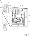
- Fig.4 shows a section of a typical coupling, the section in particular showing a shaft connection 1 for connecting a first shaft 5 and a second shaft 7.
- the second shaft 7 has a first toothing 45 for coupling with a Fig.4 not shown rotor shaft.
- Both shafts are ring-shaped and each comprise a radial area in which both shafts extend.
- the overlapping, radial area is shown in the detailed view in Fig.4 shown enlarged.
- the two shafts are arranged one behind the other and connected by pairs of spring elements, which are distributed in the circumferential direction around the axis of rotation 3.
- Each pair of spring elements comprises a first spring element 11 and a second spring element 13, each of which is designed as a leaf spring, for example as in Figures 1 to 3
- the leaf springs are each attached to the first shaft 5 and to the second shaft 7 via fastening means 35.
- the second shaft 7 is shown in a first axial position in which the spring elements are not deflected and the second shaft 7 is supported by a Fig.4 not shown rotor shaft is decoupled.
- the second shaft 7 can be moved in the axial direction 37, in particular to a second axial position which is further away from the first shaft 5 than the first axial position.
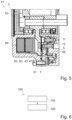
- Fig.5 shows another section of the Fig.4 illustrated clutch 41 with further components of the clutch 41, whereby only one half of the sectional view of the clutch 41 is shown.
- the clutch 41 comprises a housing 51, a rotor shaft 43 and a shaft connection with spring element pairs, a first shaft 5 and a second shaft 7.
- the housing 51 is secured against rotation.
- the rotor shaft 43 can be connected to a shaft of an electric motor (not shown) by means of screws 53, for example.
- the first shaft 5, the second shaft 7 and the rotor shaft 43 are coaxially rotatable about an axis of rotation 3.
- the second shaft 7 has, on the side of the second shaft 7 facing the rotor shaft 43, a first toothing 45 for engagement with a second toothing 47 of the rotor shaft 43.
- Fig.5 shows the second shaft 7 in a first axial position in which the spring elements are unloaded.
- the clutch 41 further comprises an electromagnet 49 with magnetic coils 50.
- the electromagnet 49 is designed to cause a magnetic force on the second shaft 7 when the magnetic coils 50 are energized, so that the second shaft 7 is pulled against the restoring force of the spring elements in the direction of the rotor shaft 43 into a second axial position in which the first toothing 45 of the second shaft 7 engages the second toothing 47 of the rotor shaft.
- the electromagnet closes a magnetic circuit through the housing 51, the rotor shaft 43 and the second shaft 7.
- Fig.6 shows a flow chart of a use 100 of a clutch 41, such as in Fig.5 shown.
- the second shaft 7 is moved in a first axial direction to couple the first shaft 5 and the second shaft 7 to the rotor shaft 43.
- the electromagnet 49 energized.
- the second shaft 7 is pulled by the magnetic force of the electromagnet 49 from a first axial position on the first shaft 5 into a second axial position, whereby the spring element pairs are preloaded without play.
- the first toothing 45 of the second shaft 7 engages with the second toothing 47 of the rotor shaft 43. With the engagement of the toothings, the first shaft 5, the second shaft 7 and the rotor shaft 43 are coupled without play and in a torsionally rigid manner in both directions of rotation.
- the second shaft 7 is moved in a second axial direction different from the first axial direction to decouple the first shaft 5 and the second shaft 7 from the rotor shaft 43.
- the current supply to the electromagnet 49 is switched off.
- the spring element pairs pull the second shaft back into the first axial position, whereby the first gear is disengaged from the second gear 47.
- the rotor shaft 43 is decoupled from the first shaft 5 and the second shaft 7.
- the clutch 41 of the Fig.5 has a "fail-safe" function, in which the rotor shaft 43 is decoupled from the first shaft 5 and the second shaft 7 if the electromagnet 49 fails or switches off.
Landscapes
- Engineering & Computer Science (AREA)
- General Engineering & Computer Science (AREA)
- Mechanical Engineering (AREA)
- Automation & Control Theory (AREA)
- Aviation & Aerospace Engineering (AREA)
- Braking Arrangements (AREA)
- Springs (AREA)
Abstract
Wellenverbindung (1), umfassend eine um eine Drehachse (3) drehbare erste Welle (5), eine koaxial zu der ersten Welle (5) angeordnete und relativ zu der ersten Welle (5) axial bewegliche zweite Welle (7), und mindestens ein Federelementpaar (9) mit jeweils einem ersten Federelement (11) und einem zweiten Federelement (13), wobei das erste Federelement (11) und das zweite Federelement (13) jeweils an der ersten Welle (5) und an der zweiten Welle (7) befestigt sind, und wobei das erste Federelement (11) und das zweite Federelement (13) axial versetzt zueinander angeordnet sind.

Description
Die Offenbarung betrifft eine Wellenverbindung, eine Kupplung und eine Verwendung einer Wellenverbindung oder einer Kupplung.The disclosure relates to a shaft connection, a coupling and a use of a shaft connection or a coupling.
Aus dem Stand der Technik sind Wellenverbindungen oder Kupplungen bekannt, wobei zwei Wellen über eine Feder verbunden sind. Die Feder kann eine Rückstellkraft in axialer Richtung auf eine der zwei Wellen gegenüber einer anderen der zwei Wellen bewirken. Beispielsweise offenbart die
Allerdings weisen aus dem Stand der Technik bekannte Wellenverbindungen oder Kupplungen Restriktionen auf, insbesondere in Bezug auf eine Verdrehsteifigkeit von Wellenverbindungen oder in Bezug auf eine von der Wellenverbindung bereitgestellte axiale Hubkraft.However, shaft connections or couplings known from the prior art have restrictions, in particular with regard to a torsional rigidity of shaft connections or with regard to an axial lifting force provided by the shaft connection.
Aufgabe der Offenbarung ist es, eine Wellenverbindung, eine Kupplung und eine Verwendung einer Wellenverbindung oder einer Kupplung anzugeben, welche gegenüber dem Stand der Technik verbessert sind. Insbesondere sollte eine Wellenverbindung angegeben werden, welche eine hohe Verdrehsteifigkeit aufweist oder eine geringe axiale Hubkraft erfordert.The object of the disclosure is to provide a shaft connection, a coupling and a use of a shaft connection or a coupling which are improved compared to the prior art. In particular, a shaft connection should be provided which has a high torsional rigidity or requires a low axial lifting force.
Die Aufgabe wird mit einer Wellenverbindung gemäß Anspruch 1 und einer Kupplung und einer Verwendung nach den nebengeordneten Ansprüchen gelöst.The object is achieved with a shaft connection according to
Gemäß einem Aspekt wird eine Wellenverbindung angegeben. Die Wellenverbindung umfasst eine um eine Drehachse drehbare erste Welle, eine koaxial zu der ersten Welle angeordnete und relativ zu der ersten Welle axial bewegliche zweite Welle, und mindestens ein Federelementpaar mit jeweils einem ersten Federelement und einem zweiten Federelement, wobei das erste Federelement und das zweite Federelement jeweils an der ersten Welle und an der zweiten Welle befestigt sind, und wobei das erste Federelement und das zweite Federelement axial versetzt zueinander angeordnet sind.According to one aspect, a shaft connection is specified. The shaft connection comprises a first shaft rotatable about an axis of rotation, a second shaft arranged coaxially to the first shaft and axially movable relative to the first shaft, and at least one pair of spring elements each having a first spring element and a second spring element, wherein the first spring element and the second spring element are each fastened to the first shaft and to the second shaft, and wherein the first spring element and the second spring element are arranged axially offset from one another.
Gemäß einem weiteren Aspekt wird eine Kupplung angegeben. Die Kupplung umfasst eine Wellenverbindung nach einer der hierin beschriebenen Ausführungsformen, und eine koaxial zu der ersten Welle und der zweiten Welle angeordnete Rotorwelle, wobei die Kupplung zum Kuppeln der ersten Welle und der zweiten Welle mit der Rotorwelle dazu eingerichtet ist, die zweite Welle axial in Richtung der Rotorwelle zu bewegen.According to a further aspect, a coupling is provided. The coupling comprises a shaft connection according to one of the embodiments described herein, and a rotor shaft arranged coaxially to the first shaft and the second shaft, wherein the coupling is designed to couple the first shaft and the second shaft to the rotor shaft in order to move the second shaft axially in the direction of the rotor shaft.
Gemäß noch einem weiteren Aspekt wird eine Verwendung einer Wellenverbindung nach einer der hierin beschriebenen Ausführungsformen oder einer Kupplung nach einer der hierin beschriebenen Ausführungsformen angegeben, mit Bewegen der zweiten Welle relativ zu der ersten Welle in einer axialen Richtung.According to yet another aspect, there is provided a use of a shaft connection according to any of the embodiments described herein or a coupling according to any of the embodiments described herein, with moving the second shaft relative to the first shaft in an axial direction.
Bei typischen Ausführungsformen umfasst die Wellenverbindung eine erste Welle. Typischerweise ist die erste Welle der Wellenverbindung um eine Drehachse drehbar. Die Begriffe "axial", "koaxial", "radial" und "in Umfangsrichtung" beziehen sich hierin insbesondere auf die Drehachse. Unter einer axialen Richtung ist insbesondere eine Richtung der Drehachse zu verstehen. Typischerweise umfasst die Wellenverbindung eine zweite Welle. Bei typischen Ausführungsformen sind die erste Welle und die zweite Welle koaxial angeordnet. Bei typischen Ausführungsformen ist die erste Welle eine Abtriebswelle. Die zweite Welle ist typischerweise eine Antriebswelle. Bei weiteren typischen Ausführungsformen kann die erste Welle eine Antriebswelle sein und die zweite Welle eine Abtriebswelle. Bei typischen Ausführungsformen ist die erste Welle oder die zweite Welle als Hohlwelle ausgebildet, insbesondere kreisringförmig. Bei weiteren typischen Ausführungsformen ist die erste Welle oder die zweite Welle als Vollwelle ausgebildet. Typischerweise sind die erste Welle und die zweite Welle aus Metall hergestellt.In typical embodiments, the shaft connection comprises a first shaft. Typically, the first shaft of the shaft connection is rotatable about an axis of rotation. The terms "axial", "coaxial", "radial" and "in the circumferential direction" refer here in particular to the axis of rotation. An axial direction is to be understood in particular as a direction of the axis of rotation. Typically, the shaft connection comprises a second shaft. In typical embodiments, the first shaft and the second shaft are arranged coaxially. In typical embodiments, the first shaft is an output shaft. The second shaft is typically a drive shaft. In further typical embodiments, the first shaft can be a drive shaft and the second shaft an output shaft. In typical embodiments, the first shaft or the second shaft is designed as a hollow shaft, in particular circular. In further typical embodiments, the first shaft or the second shaft is designed as a solid shaft. Typically, the first shaft and the second shaft are made of metal.
Bei typischen Ausführungsformen umfasst die Wellenverbindung mindestens ein Federelementpaar. Typischerweise bilden ein erstes Federelement und ein zweites Federelement ein Federelementpaar. Bei Ausführungsformen sind das erste Federelement und das zweite Federelement identisch ausgebildet. Typischerweise sind die erste Welle und die zweite Welle über das mindestens eine Federelementpaar miteinander verbunden, insbesondere drehfest miteinander verbunden.In typical embodiments, the shaft connection comprises at least one pair of spring elements. Typically, a first spring element and a second spring element form a pair of spring elements. In embodiments, the first spring element and the second spring element are identical. Typically, the first shaft and the second shaft are connected to one another via the at least one pair of spring elements, in particular connected to one another in a rotationally fixed manner.
Typischerweise sind das erste Federelement und das zweite Federelement eines Federelementpaars jeweils an der ersten Welle und an der zweiten Welle befestigt, insbesondere über kraft- oder formschlüssige Befestigungsmittel wie Schrauben oder Nieten. Bei Ausführungsformen können die erste Welle und die zweite Welle abgestufte Planflächen zur Befestigung des mindestens einen Federelementpaares aufweisen.Typically, the first spring element and the second spring element of a spring element pair are each fastened to the first shaft and to the second shaft, in particular via force-fitting or form-fitting fastening means such as screws or rivets. In embodiments, the first shaft and the second shaft can have stepped flat surfaces for fastening the at least one spring element pair.
Typischerweise sind das erste Federelement und das zweite Federelement des mindestens einen Federelementpaares axial versetzt zueinander angeordnet. Insbesondere sind das erste Federelement und das zweite Federelement axial beabstandet zueinander angeordnet. Ein axialer Abstand zwischen einem Federelement eines Federelementpaares und der ersten Welle oder der zweiten Welle kann beispielsweise durch einen axialen Abstandshalter bereitgestellt werden, welcher an der Befestigungsposition des Federelements zwischen dem Federelement und der ersten Welle oder der zweiten Welle angeordnet ist. Abstandshalter können als Teil von Befestigungsmitteln zum Befestigen der Federelemente an der ersten Welle und an der zweiten Welle ausgebildet sein. Ein axialer Abstand zwischen den Federelementen eines Federelementpaares kann durch unterschiedliche Abstände der Federelemente zu der ersten Welle oder der zweiten Welle bereitgestellt werden. Unterschiedliche axiale Abstände der Federelemente zu der ersten Welle oder der zweiten Welle können beispielsweise durch die Verwendung unterschiedlicher Abstandshalter an den Befestigungspositionen der Federelemente bereitgestellt werden.Typically, the first spring element and the second spring element of the at least one spring element pair are arranged axially offset from one another. In particular, the first spring element and the second spring element are arranged axially spaced from one another. An axial distance between a spring element of a spring element pair and the first shaft or the second shaft can be provided, for example, by an axial spacer which is arranged at the fastening position of the spring element between the spring element and the first shaft or the second shaft. Spacers can be designed as part of fastening means for fastening the spring elements to the first shaft and to the second shaft. An axial distance between the spring elements of a spring element pair can be provided by different distances of the spring elements to the first shaft or the second shaft. Different axial distances of the spring elements to the first shaft or the second shaft can be provided, for example, by using different spacers at the fastening positions of the spring elements.
Bei typischen Ausführungsformen ist das erste Federelement dazu eingerichtet, in einer ersten Drehrichtung der ersten Welle und der zweiten Welle auf Zug belastet zu werden. Typischerweise ist das zweite Federelement dazu eingerichtet, in einer von der ersten Drehrichtung verschiedenen, zweiten Drehrichtung der ersten Welle und der zweiten Welle auf Zug belastet zu werden. Bei Ausführungsformen kann mindestens ein Federelementpaar insbesondere derart angeordnet sein, dass bei Drehung der ersten Welle und der zweiten Welle stets ein Federelement des Federelementpaares unabhängig von der Drehrichtung auf Zug belastet wird, während das andere Federelement des Federelementpaares auf Druck belastet wird. Ausführungsformen können insbesondere eine hohe Verdrehsteifigkeit in beiden Drehrichtungen um die Drehachse aufweisen. Beispielsweise kann eine hohe Verdrehsteifigkeit erreicht werden, ohne ein Federelement zur Vermeidung eines Knickens unter Druckbelastung besonders massiv auszugestalten.In typical embodiments, the first spring element is designed to be subjected to a tensile load in a first direction of rotation of the first shaft and the second shaft. Typically, the second spring element is designed to be subjected to a tensile load in a second direction of rotation of the first shaft and the second shaft that is different from the first direction of rotation. In embodiments, at least one pair of spring elements can be arranged in particular in such a way that when the first shaft and the second shaft rotate, one spring element of the pair of spring elements is always subjected to a tensile load, regardless of the direction of rotation, while the other spring element of the pair of spring elements is subjected to a compressive load. Embodiments can in particular have a high torsional rigidity in both directions of rotation about the axis of rotation. For example, a high torsional rigidity can be achieved without making a spring element particularly solid to avoid buckling under compressive load.
Typischerweise ist die zweite Welle relativ zu der ersten Welle axial beweglich. Typischerweise ist die Beweglichkeit der zweiten Welle relativ zu der ersten Welle in axialer Richtung begrenzt. Typischerweise ist die Beweglichkeit der zweiten Welle axial in Richtung der ersten Welle durch einen Anschlag der ersten Welle oder durch eine maximale Auslenkungsposition des mindestens einen Federelementpaares in Richtung der ersten Welle begrenzt. Typischerweise ist die Beweglichkeit der zweiten Welle in axialer Richtung weg von der ersten Welle durch das mindestens eine Federelementpaar begrenzt. Typischerweise ist die maximale axiale Auslenkung weg von der ersten Welle der zweiten Welle relativ zu der ersten Welle durch einen axialen Abstand zwischen dem ersten Federelement und dem zweiten Federelement begrenzt oder vorbestimmt, wobei sich der axiale Abstand zwischen dem ersten Federelement und dem zweiten Federelement auf den axialen Abstand in einem nicht ausgelenkten Zustand des ersten Federelements und des zweiten Federelements bezieht.Typically, the second shaft is axially movable relative to the first shaft. Typically, the mobility of the second shaft relative to the first shaft is limited in the axial direction. Typically, the mobility of the second shaft is limited axially in the direction of the first shaft by a stop of the first shaft or by a maximum deflection position of the at least one pair of spring elements in the direction of the first shaft. Typically, the mobility of the second shaft in the axial direction away from the first shaft is limited by the at least one pair of spring elements. Typically, the maximum axial deflection away from the first shaft of the second shaft relative to the first shaft is limited or predetermined by an axial distance between the first spring element and the second spring element, wherein the axial distance between the first spring element and the second spring element refers to the axial distance in a non-deflected state of the first spring element and the second spring element.
Bei typischen Ausführungsformen sind das erste Federelement und das zweite Federelement jeweils als eine Blattfeder ausgebildet. Typischerweise weist eine Blattfeder zwei parallele, flache Seiten auf. Eine Dicke der Blattfeder, gemessen zwischen den zwei flachen Seiten, ist typischerweise kleiner als eine Länge oder eine Breite der Blattfeder, insbesondere mindestens fünfmal oder mindestens zehnmal kleiner. Typischerweise ist eine Blattfeder länglich ausgebildet. Beispielsweise kann die Länge der Blattfeder mindestens doppelt so groß sein wie die Breite der Blattfeder, insbesondere mindestens dreimal so groß oder mindestens viermal so groß. Bei typischen Ausführungsformen ist eine Blattfeder aus Metall, insbesondere aus Federstahlblech hergestellt.In typical embodiments, the first spring element and the second spring element are each designed as a leaf spring. Typically, a leaf spring has two parallel, flat sides. A thickness of the leaf spring, measured between the two flat sides, is typically smaller than a length or a width of the leaf spring, in particular at least five times or at least ten times smaller. Typically, a leaf spring is elongated. For example, the length of the leaf spring can be at least twice as large as the width of the leaf spring, in particular at least three times as large or at least four times as large. In typical embodiments, a leaf spring is made of metal, in particular of spring steel sheet.
Typischerweise ist eine jeweilige Blattfeder des ersten Federelements oder des zweiten Federelements zumindest im Wesentlichen parallel zu einer zu der Drehachse orthogonalen Ebene oder einer Planfläche der ersten Welle oder der zweiten Welle ausgerichtet, insbesondere wenn die Blattfeder nicht aus der Ruhelage der Blattfeder ausgelenkt ist. Typischerweise sind die flachen Seiten der Blattfeder zumindest im Wesentlichen parallel zu einer zu der Drehachse orthogonalen Ebene ausgerichtet. Unter einer zumindest im Wesentlichen parallelen Ausrichtung ist insbesondere eine Abweichung von maximal 10 Grad, insbesondere von maximal 5 Grad oder von maximal 2 Grad zu verstehen.Typically, a respective leaf spring of the first spring element or of the second spring element is aligned at least substantially parallel to a plane orthogonal to the axis of rotation or a flat surface of the first shaft or the second shaft, in particular when the leaf spring is not deflected from the rest position of the leaf spring. Typically, the flat sides of the leaf spring are aligned at least substantially parallel to a plane orthogonal to the axis of rotation. An at least substantially parallel alignment is understood to mean in particular a deviation of a maximum of 10 degrees, in particular of a maximum of 5 degrees or of a maximum of 2 degrees.
Gemäß typischen Ausführungsformen ist eine jeweilige Blattfeder des ersten Federelements oder des zweiten Federelements bogenförmig ausgebildet, insbesondere kreisbogenförmig oder bananenförmig. Die Blattfeder kann beispielsweise im Wesentlichen in Form eines Kreisringausschnittes ausgebildet sein. Typischerweise ist die Blattfeder bogenförmig entlang einer Längsrichtung der Blattfeder ausgebildet. Typischerweise ist die Blattfeder radial nach außen gewölbt in der Wellenverbindung angeordnet. Bei Ausführungsformen erstreckt sich die Blattfeder im Wesentlichen in Umfangsrichtung um die Drehachse. Bei Ausführungsformen liegt ein Bogenmittelpunkt einer bogenförmig ausgebildeten Blattfeder radial innerhalb der radial innersten Befestigungsposition des mindestens einen Federelementpaares. Mit bogenförmigen Federelementen kann beispielsweise bei Ausführung der ersten Welle oder der zweiten Welle als Hohlwelle ein größerer Innendurchmesser der ersten Welle oder der zweiten Welle bereitgestellt werden. Bei weiteren typischen Ausführungsformen ist eine jeweilige Blattfeder des ersten Federelements oder des zweiten Federelements gerade ausgebildet. Eine gerade Ausgestaltung kann eine höhere rotative Steifigkeit der Blattfeder bereitstellen.According to typical embodiments, a respective leaf spring of the first spring element or of the second spring element is arcuate, in particular circular arc-shaped or banana-shaped. The leaf spring can, for example, be designed essentially in the form of a circular ring cutout. Typically, the leaf spring is arcuate along a longitudinal direction of the leaf spring. Typically, the leaf spring is arranged in the shaft connection so as to be curved radially outward. In embodiments, the leaf spring extends essentially in the circumferential direction around the axis of rotation. In embodiments, an arc center of an arcuate leaf spring lies radially within the radially innermost fastening position of the at least one pair of spring elements. With arcuate spring elements, for example, when the first shaft or the second shaft is designed as a hollow shaft, a larger inner diameter of the first shaft or the second shaft can be provided. In In other typical embodiments, a respective leaf spring of the first spring element or the second spring element is designed to be straight. A straight design can provide a higher rotational stiffness of the leaf spring.
Bei typischen Ausführungsformen sind das erste Federelement und das zweite Federelement eines Federelementpaares überkreuzt angeordnet. Insbesondere überkreuzen sich das erste Federelement und das zweite Federelement in einer Ansicht entlang der Drehachse. Das erste Federelement und das zweite Federelement können sich symmetrisch überkreuzen. Die überkreuzte Anordnung der Federelemente kann eine hohe drehrichtungsunabhängige Steifigkeit bereitstellen. Bei Ausführungsformen ist das erste Federelement an einer ersten Befestigungsposition an der ersten Welle und an einer radial innerhalb der ersten Befestigungsposition vorgesehenen, zweiten Befestigungsposition an der zweiten Welle befestigt. Typischerweise ist das zweite Federelement an einer dritten Befestigungsposition an der ersten Welle und an einer radial innerhalb der dritten Befestigungsposition vorgesehenen, vierten Befestigungsposition an der zweiten Welle befestigt. Typischerweise ist die dritte Befestigungsposition in einer ersten Umfangsrichtung um einen ersten Winkel versetzt zu der ersten Befestigungsposition angeordnet. Typischerweise ist die vierte Befestigungsposition in einer von der ersten Umfangsrichtung verschiedenen, zweiten Umfangsrichtung um einen zweiten Winkel versetzt zu der zweiten Befestigungsposition angeordnet.In typical embodiments, the first spring element and the second spring element of a spring element pair are arranged in a crossed manner. In particular, the first spring element and the second spring element cross each other in a view along the axis of rotation. The first spring element and the second spring element can cross each other symmetrically. The crossed arrangement of the spring elements can provide a high degree of rigidity independent of the direction of rotation. In embodiments, the first spring element is fastened to the first shaft at a first fastening position and to the second shaft at a second fastening position provided radially inside the first fastening position. Typically, the second spring element is fastened to the first shaft at a third fastening position and to the second shaft at a fourth fastening position provided radially inside the third fastening position. Typically, the third fastening position is arranged offset from the first fastening position by a first angle in a first circumferential direction. Typically, the fourth fastening position is arranged offset from the second fastening position by a second angle in a second circumferential direction different from the first circumferential direction.
Bei typischen Ausführungsformen erstrecken sich das erste Federelement und das zweite Federelement jeweils über denselben Winkelbereich um die Drehachse. Typischerweise umfasst der Winkelbereich mindestens 60 Grad, insbesondere mindestens 70 Grad, oder maximal 130 Grad, insbesondere maximal 120 Grad. Insbesondere kann der Winkelbereich mindestens 70 Grad und maximal 120 Grad umfassen, beispielsweise ungefähr 90 Grad. Eine große Federlänge der Federelemente kann beispielsweise eine geringe Rückstellkraft der Federelemente bereitstellen. Eine geringe Rückstellkraft kann eine weiche axiale Verbindung zwischen der ersten Welle und der zweiten Welle bereitstellen, so dass insbesondere eine zum axialen Bewegen der zweiten Welle eingerichtete Hubvorrichtung nur eine geringe Hubkraft zum Überwinden der Rückstellkraft benötigt. Typischerweise sind die erste Befestigungsposition des ersten Federelements und die vierte Befestigungsposition des zweiten Federelements an einer ersten Winkelposition bezüglich der Drehachse angeordnet. Typischerweise sind die zweite Befestigungsposition des ersten Federelements und die dritte Befestigungsposition des zweiten Federelements an einer von der ersten Winkelposition verschiedenen, zweiten Winkelposition angeordnet. Typischerweise schließen die erste Winkelposition und die zweite Winkelposition einen der hierin beschriebenen Winkelbereiche ein.In typical embodiments, the first spring element and the second spring element each extend over the same angular range around the axis of rotation. Typically, the angular range comprises at least 60 degrees, in particular at least 70 degrees, or a maximum of 130 degrees, in particular a maximum of 120 degrees. In particular, the angular range can comprise at least 70 degrees and a maximum of 120 degrees, for example approximately 90 degrees. A large spring length of the spring elements can, for example, provide a low restoring force of the spring elements. A low restoring force can provide a soft axial connection between the first shaft and the second shaft, so that in particular a lifting device designed to move the second shaft axially only requires a low lifting force to overcome the restoring force. Typically, the first fastening position of the first spring element and the fourth Fastening position of the second spring element is arranged at a first angular position with respect to the axis of rotation. Typically, the second fastening position of the first spring element and the third fastening position of the second spring element are arranged at a second angular position different from the first angular position. Typically, the first angular position and the second angular position enclose one of the angular ranges described herein.
Gemäß typischen Ausführungsformen weisen das erste Federelement und das zweite Federelement jeweils eine Befestigungsposition auf einem ersten Kreis um die Drehachse an der ersten Welle auf. Typischerweise weisen das erste Federelement und das zweite Federelement jeweils eine weitere Befestigungsposition auf einem zweiten Kreis um die Drehachse an der zweiten Welle auf. Die Befestigungsposition und die weitere Befestigungsposition eines Federelements liegen typischerweise an gegenüberliegenden Enden des Federelements. Typischerweise weisen der erste Kreis und der zweite Kreis unterschiedliche Radien auf. Beispielsweise weist der erste Kreis bei Ausführungsformen einen größeren Radius auf als der zweite Kreis. Insbesondere können die erste Befestigungsposition des ersten Federelements und die dritte Befestigungsposition des zweiten Federelements auf dem ersten Kreis um die Drehachse vorgesehen sein. Die zweite Befestigungsposition des ersten Federelements und die vierte Befestigungsposition des zweiten Federelements können auf dem zweiten Kreis um die Drehachse vorgesehen sein. Bei weiteren typischen Ausführungsformen kann der erste Kreis einen kleineren Radius als der zweite Kreis aufweisen.According to typical embodiments, the first spring element and the second spring element each have a fastening position on a first circle around the axis of rotation on the first shaft. Typically, the first spring element and the second spring element each have a further fastening position on a second circle around the axis of rotation on the second shaft. The fastening position and the further fastening position of a spring element are typically located at opposite ends of the spring element. Typically, the first circle and the second circle have different radii. For example, in embodiments, the first circle has a larger radius than the second circle. In particular, the first fastening position of the first spring element and the third fastening position of the second spring element can be provided on the first circle around the axis of rotation. The second fastening position of the first spring element and the fourth fastening position of the second spring element can be provided on the second circle around the axis of rotation. In further typical embodiments, the first circle can have a smaller radius than the second circle.
Bei typischen Ausführungsformen umfasst die Wellenverbindung mindestens zwei Federelementpaare, insbesondere mindestens drei Federelementpaare. Beispielsweise kann die Wellenverbindung genau zwei, genau drei oder genau vier Federelementpaare umfassen. Die Anzahl der Federelementpaare kann beispielsweise in Abhängigkeit eines bereitzustellenden axialen Hubs der zweiten Welle oder eines zu übertragenden Drehmoments gewählt werden. Bei einer beispielhaften Ausführungsform weist die Wellenverbindung genau drei Federelementpaare auf. Insbesondere kann ein großer axialer Hub erreicht und ein hohes Drehmoment übertragen werden.In typical embodiments, the shaft connection comprises at least two pairs of spring elements, in particular at least three pairs of spring elements. For example, the shaft connection can comprise exactly two, exactly three or exactly four pairs of spring elements. The number of pairs of spring elements can be selected, for example, depending on an axial stroke of the second shaft to be provided or a torque to be transmitted. In an exemplary embodiment, the shaft connection has exactly three pairs of spring elements. In particular, a large axial stroke can be achieved and a high torque can be transmitted.
Bei typischen Ausführungsformen mit mehr als einem Federelementpaar umfasst jedes Federelementpaar ein erstes Federelement und ein zweites Federelement, insbesondere ein erstes Federelement und ein zweites Federelement nach hierin beschriebenen Ausführungsformen. Typischerweise sind alle ersten Federelemente der Wellenverbindung identisch ausgebildet. Typischerweise sind alle zweiten Federelemente der Wellenverbindung identisch ausgebildet. Insbesondere können alle ersten Federelemente und alle zweiten Federelemente identisch ausgebildet sein. Bei Ausführungsformen sind die mindestens zwei Federelementpaare in Umfangsrichtung um die Drehachse verteilt angeordnet, insbesondere gleichmäßig in Umfangsrichtung verteilt angeordnet. Typischerweise sind die mindestens zwei Federelementpaare in Umfangsrichtung getrennt voneinander angeordnet, insbesondere ohne eine Überlappung der Federelementpaare in Umfangsrichtung.In typical embodiments with more than one pair of spring elements, each pair of spring elements comprises a first spring element and a second spring element, in particular a first spring element and a second spring element according to embodiments described herein. Typically, all first spring elements of the shaft connection are identical. Typically, all second spring elements of the shaft connection are identical. In particular, all first spring elements and all second spring elements can be identical. In embodiments, the at least two pairs of spring elements are arranged distributed in the circumferential direction around the axis of rotation, in particular evenly distributed in the circumferential direction. Typically, the at least two pairs of spring elements are arranged separately from one another in the circumferential direction, in particular without an overlap of the pairs of spring elements in the circumferential direction.
Gemäß Ausführungsformen sind die erste Welle und die zweite Welle in einer axialen Richtung hintereinander angeordnet. Bei Ausführungsformen können eine radiale Erstreckung der ersten Welle und eine radiale Erstreckung der zweiten Welle jeweils einen überlappenden, radialen Bereich umfassen. Die erste Welle und die zweite Welle können in dem überlappenden, radialen Bereich axial hintereinander angeordnet sein. Das erste Federelement und das zweite Federelement können in dem überlappenden, radialen Bereich an der ersten Welle oder an der zweiten Welle befestigt sein. Insbesondere können die Befestigungspositionen des ersten Federelements und des zweiten Federelements an der ersten Welle und an der zweiten Welle in dem überlappenden, radialen Bereich vorgesehen sein.According to embodiments, the first shaft and the second shaft are arranged one behind the other in an axial direction. In embodiments, a radial extension of the first shaft and a radial extension of the second shaft can each comprise an overlapping, radial region. The first shaft and the second shaft can be arranged axially one behind the other in the overlapping, radial region. The first spring element and the second spring element can be fastened to the first shaft or to the second shaft in the overlapping, radial region. In particular, the fastening positions of the first spring element and the second spring element on the first shaft and on the second shaft can be provided in the overlapping, radial region.
Typischerweise ist die zweite Welle relativ zu der ersten Welle in axialer Richtung beweglich. Typischerweise ist die zweite Welle in axialer Richtung relativ zu der ersten Welle zumindest zwischen zwei axialen Positionen beweglich, insbesondere zwischen einer ersten axialen Position und einer zweiten axialen Position. Die erste axiale Position kann eine axiale Position nahe der ersten Welle sein, insbesondere an einem axialen Anschlag des Gehäuses oder der ersten Welle, oder eine Ruhestellung, in welcher das mindestens eine Federelementpaar in einem axial entlasteten Zustand bezüglich der ersten Welle ist. Die zweite axiale Position ist typischerweise weiter entfernt von der ersten Welle als die erste axiale Position.Typically, the second shaft is movable in the axial direction relative to the first shaft. Typically, the second shaft is movable in the axial direction relative to the first shaft at least between two axial positions, in particular between a first axial position and a second axial position. The first axial position can be an axial position close to the first shaft, in particular at an axial stop of the housing or the first shaft, or a rest position in which the at least one pair of spring elements is in an axially unloaded state with respect to the first shaft. The second axial position is typically further away from the first shaft than the first axial position.
Typischerweise ist die zweite Welle unter Wirkung einer von dem mindestens einen Federelementpaar erzeugten Federkraft in axialer Richtung beweglich. Die Federkraft kann hierin insbesondere auch als Rückstellkraft des mindestens einen Federelementpaars bezeichnet werden. Insbesondere ist das mindestens eine Federelementpaar typischerweise dazu eingerichtet, bei einer axialen Bewegung der zweiten Welle relativ zu der ersten Welle eine Rückstellkraft auf die zweite Welle zu bewirken. Typischerweise ist das mindestens eine Federelementpaar dazu eingerichtet, bei einer Auslenkung oder Bewegung der zweiten Welle von der ersten axialen Position zu der zweiten axialen Position eine Rückstellkraft auf die zweite Welle in Richtung der ersten axialen Position zu bewirken. Bei Positionierung der zweiten Welle an der zweiten axialen Position kann die Auslenkung der Federelemente insbesondere eine Spielfreiheit zwischen der ersten Welle und der zweiten Welle bereitstellen. Bei weiteren Ausführungsformen kann das mindestens eine Federelementpaar dazu eingerichtet sein, bei einer Auslenkung oder Bewegung der zweiten Welle in axialer Richtung von der zweiten axialen Position hin zu der ersten axialen Position eine Rückstellkraft auf die zweite Welle in Richtung der zweiten axialen Position zu bewirken.Typically, the second shaft is movable in the axial direction under the action of a spring force generated by the at least one pair of spring elements. The spring force can also be referred to herein in particular as the restoring force of the at least one pair of spring elements. In particular, the at least one pair of spring elements is typically designed to cause a restoring force on the second shaft when the second shaft moves axially relative to the first shaft. Typically, the at least one pair of spring elements is designed to cause a restoring force on the second shaft in the direction of the first axial position when the second shaft is deflected or moved from the first axial position to the second axial position. When the second shaft is positioned at the second axial position, the deflection of the spring elements can in particular provide a freedom of play between the first shaft and the second shaft. In further embodiments, the at least one pair of spring elements can be designed to cause a restoring force on the second shaft in the direction of the second axial position when the second shaft is deflected or moved in the axial direction from the second axial position to the first axial position.
Gemäß typischen Ausführungsformen ist eine maximale axiale Auslenkung der zweiten Welle relativ zu der ersten Welle durch die Anordnung und Form des ersten Federelements und des zweiten Federelements bestimmt oder begrenzt, insbesondere durch den axialen Abstand des ersten Federelements und des zweiten Federelements zueinander. Die maximale axiale Auslenkung der zweiten Welle kann insbesondere dem axialen Abstand zwischen dem ersten Federelement und dem zweiten Federelement entsprechen.According to typical embodiments, a maximum axial deflection of the second shaft relative to the first shaft is determined or limited by the arrangement and shape of the first spring element and the second spring element, in particular by the axial distance of the first spring element and the second spring element from one another. The maximum axial deflection of the second shaft can in particular correspond to the axial distance between the first spring element and the second spring element.
Bei Ausführungsformen weist die zweite Welle eine Verzahnung auf. Typischerweise ist die Verzahnung auf der der ersten Welle abgewandten Seite der zweiten Welle vorgesehen. Die Verzahnung kann beispielsweise eine Stirnverzahnung oder Planverzahnung sein, insbesondere eine Hirthverzahnung.In embodiments, the second shaft has a toothing. Typically, the toothing is provided on the side of the second shaft facing away from the first shaft. The toothing can be, for example, a spur toothing or a face toothing, in particular a Hirth toothing.
Gemäß typischen Ausführungsformen umfasst eine Kupplung eine Wellenverbindung nach einer der hierin beschriebenen Ausführungsformen. Typischerweise sind die erste Welle und die zweite Welle der Wellenverbindung durch das mindestens eine Federelementpaar der Wellenverbindung zumindest im Wesentlichen spielfrei oder zumindest im Wesentlichen verdrehsteif miteinander verbunden. Typische Kupplungen können für einen Aktuator in einem Fluggerät eingerichtet sein, beispielsweise für einen Aktuator einer Fluggerätsteuerung.According to typical embodiments, a coupling comprises a shaft connection according to one of the embodiments described herein. Typically, the first shaft and the second shaft of the shaft connection are at least substantially free of play or at least essentially torsionally rigid. Typical couplings can be designed for an actuator in an aircraft, for example for an actuator of an aircraft control system.
Typischerweise umfasst die Kupplung eine koaxial zu der ersten Welle und der zweiten Welle angeordnete Rotorwelle. Die Kupplung kann ein Gehäuse umfassen, welches insbesondere zumindest teilweise die Rotorwelle umgreift. Die Rotorwelle ist typischerweise in axialer Richtung unbeweglich bezüglich der ersten Welle angeordnet. Die Kupplung ist typischerweise dazu eingerichtet, die erste Welle und die zweite Welle mit der Rotorwelle zu kuppeln. Typischerweise ist die Kupplung dazu eingerichtet, die zweite Welle axial in Richtung der Rotorwelle zu bewegen, um die erste Welle und die zweite Welle mit der Rotorwelle zu kuppeln. Typischerweise kann die zweite Welle zum Entkuppeln der Rotorwelle von der ersten Welle und der zweiten Welle in axialer Richtung weg von der Rotorwelle bewegt werden. Die Rotorwelle kann typischerweise mit der Welle eines Antriebs, insbesondere eines Elektromotors oder eines Hydraulikaggregats verbunden sein.Typically, the coupling comprises a rotor shaft arranged coaxially with the first shaft and the second shaft. The coupling can comprise a housing which in particular at least partially surrounds the rotor shaft. The rotor shaft is typically arranged immovably in the axial direction with respect to the first shaft. The coupling is typically designed to couple the first shaft and the second shaft to the rotor shaft. Typically, the coupling is designed to move the second shaft axially in the direction of the rotor shaft in order to couple the first shaft and the second shaft to the rotor shaft. Typically, the second shaft can be moved in the axial direction away from the rotor shaft to decouple the rotor shaft from the first shaft and the second shaft. The rotor shaft can typically be connected to the shaft of a drive, in particular an electric motor or a hydraulic unit.
Typischerweise kann die zweite Welle an einer ersten axialen Position angeordnet werden, in welcher die Rotorwelle von der ersten Welle und der zweiten Welle entkuppelt ist. Typischerweise kann die zweite Welle an einer zweiten axialen Position angeordnet werden, in welcher die Rotorwelle mit der ersten Welle und der zweiten Welle gekuppelt ist. Insbesondere können bei der Anordnung der zweiten Welle an der zweiten axialen Position die zweite Welle und die Rotorwelle in direktem Kontakt stehen und beispielsweise reibschlüssig oder formschlüssig verbunden sein. Bei Ausführungsformen weist die zweite Welle eine erste Verzahnung auf. Die Rotorwelle weist typischerweise eine zum Eingriff mit der ersten Verzahnung eingerichtete zweite Verzahnung auf. Die erste Verzahnung und die zweite Verzahnung können jeweils beispielsweise eine Stirnverzahnung oder eine Planverzahnung sein, insbesondere eine Hirthverzahnung.Typically, the second shaft can be arranged at a first axial position in which the rotor shaft is decoupled from the first shaft and the second shaft. Typically, the second shaft can be arranged at a second axial position in which the rotor shaft is coupled to the first shaft and the second shaft. In particular, when the second shaft is arranged at the second axial position, the second shaft and the rotor shaft can be in direct contact and can be connected, for example, in a frictional or positive manner. In embodiments, the second shaft has a first toothing. The rotor shaft typically has a second toothing designed to engage with the first toothing. The first toothing and the second toothing can each be, for example, a spur toothing or a face toothing, in particular a Hirth toothing.
Bei typischen Ausführungsformen umfasst die Kupplung eine Hubvorrichtung zum Bewegen der zweiten Welle in axialer Richtung mittels einer von der Hubvorrichtung erzeugten Hubkraft. Gemäß typischen Ausführungsformen umfasst die Hubvorrichtung einen Elektromagneten, insbesondere eine oder mehrere Magnetspulen. Der Elektromagnet kann in einem Gehäuse der Kupplung angeordnet sein. Der Elektromagnet ist typischerweise eingerichtet zum Bewegen der zweiten Welle gegen eine Rückstellkraft des mindestens einen Federelementpaares von einer ersten axialen Position zu einer zweiten axialen Position. Die erste axiale Position und die zweite axiale Position können bezüglich der ersten Welle und der Rotorwelle nach hierin beschriebenen Ausführungsformen vorgesehen sein. Die Bewegung zwischen der ersten axialen Position und der zweiten axialen Position kann hierin auch als "Hub" oder als "axialer Hub" bezeichnet werden. Typischerweise ist die Kupplung eingerichtet, einen definierten axialen Hub der zweiten Welle zum Kuppeln oder Entkuppeln auszuführen.In typical embodiments, the coupling comprises a lifting device for moving the second shaft in the axial direction by means of a lifting force generated by the lifting device. According to typical embodiments, the lifting device comprises an electromagnet, in particular one or more magnetic coils. The electromagnet can be arranged in a housing of the coupling. The electromagnet is typically configured to move the second shaft against a restoring force of the at least one pair of spring elements from a first axial position to a second axial position. The first axial position and the second axial position can be provided with respect to the first shaft and the rotor shaft according to embodiments described herein. The movement between the first axial position and the second axial position can also be referred to herein as a "stroke" or as an "axial stroke". Typically, the coupling is configured to carry out a defined axial stroke of the second shaft for coupling or uncoupling.
Typischerweise wirkt die Rückstellkraft bei Anordnung der zweiten Welle an der zweiten axialen Position in Richtung der ersten axialen Position. Typischerweise wirkt eine Magnetkraft des Elektromagneten, welche auf eine an der ersten axialen Position angeordnete zweite Welle ausgeübt wird, in Richtung der zweiten axialen Position. Die Magnetkraft wird typischerweise bei Bestromung des Elektromagneten ausgeübt. Die Magnetkraft kann über einen magnetischen Kreis bewirkt werden. Der magnetische Kreis kann den Elektromagneten, die zweite Welle und beispielsweise das Gehäuse oder die Rotorwelle umfassen. Typischerweise ist die Bestromung des Elektromagneten zum Bewegen der zweiten Welle an die zweite axiale Position geeignet, insbesondere zum Kuppeln der ersten Welle und der zweiten Welle mit der Rotorwelle. Der Elektromagnet ist typischerweise dazu eingerichtet, bei Bestromung des Elektromagneten eine Magnetkraft auf die zweite Welle auszuüben, welche zumindest gleich groß wie die Rückstellkraft des mindestens einen Federelementpaares auf die zweite Welle an der zweiten axialen Position ist.Typically, the restoring force acts in the direction of the first axial position when the second shaft is arranged at the second axial position. Typically, a magnetic force of the electromagnet, which is exerted on a second shaft arranged at the first axial position, acts in the direction of the second axial position. The magnetic force is typically exerted when the electromagnet is energized. The magnetic force can be caused by a magnetic circuit. The magnetic circuit can include the electromagnet, the second shaft and, for example, the housing or the rotor shaft. Typically, the energization of the electromagnet is suitable for moving the second shaft to the second axial position, in particular for coupling the first shaft and the second shaft to the rotor shaft. The electromagnet is typically designed to exert a magnetic force on the second shaft when the electromagnet is energized, which is at least as large as the restoring force of the at least one pair of spring elements on the second shaft at the second axial position.
Das mindestens eine Federelementpaar ist typischerweise dazu eingerichtet, die zweite Welle bei unbestromtem Elektromagneten an die erste axiale Position zu bewegen, um die Rotorwelle von der ersten Welle und der zweiten Welle zu entkuppeln. Insbesondere kann das mindestens eine Federelementpaar bei Ausführungsformen die zweite Welle mit einer ersten Verzahnung aus einem Eingriff mit einer zweiten Verzahnung der Rotorwelle ausrücken. Typische Ausführungsformen können insbesondere als Kupplung mit einer "fail-safe"-Funktion ausgeführt sein, wobei bei einem Versagen oder Abschalten der Bestromung des Elektromagneten die Kupplung öffnet. Typischerweise wird die zweite Welle in Abwesenheit der Magnetkraft durch das mindestens eine Federelementpaar in Richtung der ersten Welle und an die erste axiale Position gezogen. Insbesondere wird die Rotorwelle von der ersten Welle und der zweiten Welle entkuppelt. In Ausführungsformen werden die erste Welle und die zweite Welle gegenüber dem Gehäuse festgesetzt oder gebremst.The at least one pair of spring elements is typically designed to move the second shaft to the first axial position when the electromagnet is de-energized in order to decouple the rotor shaft from the first shaft and the second shaft. In particular, in embodiments, the at least one pair of spring elements can disengage the second shaft with a first toothing from engagement with a second toothing of the rotor shaft. Typical embodiments can in particular be designed as a clutch with a "fail-safe" function, wherein the clutch opens in the event of a failure or switching off of the power supply to the electromagnet. Typically, the second shaft is in In the absence of magnetic force, the rotor shaft is pulled towards the first shaft and to the first axial position by the at least one pair of spring elements. In particular, the rotor shaft is decoupled from the first shaft and the second shaft. In embodiments, the first shaft and the second shaft are fixed or braked relative to the housing.
Bei weiteren typischen Ausführungsformen kann der Elektromagnet dazu eingerichtet sein, eine Magnetkraft auf die zweite Welle in Richtung der ersten axialen Position auszuüben und insbesondere an die erste axiale Position zu bewegen. Das mindestens eine Federelementpaar kann eingerichtet sein, eine Federkraft auf eine an der ersten axialen Position angeordnete zweite Welle in Richtung der zweiten axialen Position zu bewirken. Insbesondere kann das mindestens eine Federelementpaar dazu eingerichtet sein, die zweite Welle bei unbestromtem Elektromagneten von der ersten axialen Position an die zweite axiale Position zu bewegen. Insbesondere ist die Rotorwelle bei unbestromtem Elektromagneten mit der ersten Welle und der zweiten Welle gekuppelt. Die Kupplung kann eine "fail-safe"-Funktion aufweisen, um bei einem Versagen oder Abschalten der Bestromung des Elektromagneten die Kupplung zu schließen.In further typical embodiments, the electromagnet can be designed to exert a magnetic force on the second shaft in the direction of the first axial position and in particular to move it to the first axial position. The at least one pair of spring elements can be designed to cause a spring force on a second shaft arranged at the first axial position in the direction of the second axial position. In particular, the at least one pair of spring elements can be designed to move the second shaft from the first axial position to the second axial position when the electromagnet is de-energized. In particular, the rotor shaft is coupled to the first shaft and the second shaft when the electromagnet is de-energized. The clutch can have a "fail-safe" function in order to close the clutch if the power to the electromagnet fails or is switched off.
Bei weiteren typischen Ausführungsformen umfasst die Hubvorrichtung alternativ oder zusätzlich zu dem Elektromagneten eine mechanische Hubvorrichtung zum Bereitstellen einer mechanischen Hubkraft, eine hydraulische Hubvorrichtung zum Bereitstellen einer hydraulischen Hubkraft oder eine pneumatische Hubvorrichtung zum Bereitstellen einer pneumatischen Hubkraft. Typischerweise stellt die Hubvorrichtung die Hubkraft anstelle oder zusätzlich zu der Magnetkraft des Elektromagneten in axialer Richtung zum Kuppeln oder Entkuppeln der Kupplung bereit. Die Hubkraft wirkt typischerweise in axialer Richtung entgegen der Rückstellkraft des mindestens einen Federelementpaars. Bei weiteren typischen Ausführungsformen umfasst die Hubvorrichtung einen Elektromagneten und eine weitere mechanische, hydraulische oder pneumatische Hubvorrichtung, welche eine Hubkraft in der gleichen axialen Richtung wie die Rückstellkraft bereitstellt. Der Elektromagnet kann eingerichtet sein, eine Magnetkraft in axialer Richtung entgegen der Hubkraft und entgegen der Rückstellkraft aufzubringen, insbesondere um die Hubkraft und die Rückstellkraft zu überwinden und die zweite Welle axial in Richtung der Magnetkraft zu bewegen. Bei typischen Ausführungsformen kann die Verwendung eines Elektromagneten in einer Hubvorrichtung oder als Hubvorrichtung den Vorteil haben, dass ein Elektromagnet schnell ansteuerbar sein kann, oder einfach oder kompakt im Aufbau sein kann. Das mindestens eine Federelementpaar kann gemäß hierin beschriebenen Ausführungsformen mit einer geringen Rückstellkraft bereitgestellt werden, so dass der Elektromagnet zum Aufbringen der nötigen Magnetkraft klein und leicht dimensioniert werden kann.In further typical embodiments, the lifting device comprises, alternatively or in addition to the electromagnet, a mechanical lifting device for providing a mechanical lifting force, a hydraulic lifting device for providing a hydraulic lifting force or a pneumatic lifting device for providing a pneumatic lifting force. Typically, the lifting device provides the lifting force instead of or in addition to the magnetic force of the electromagnet in the axial direction for coupling or uncoupling the coupling. The lifting force typically acts in the axial direction against the restoring force of the at least one pair of spring elements. In further typical embodiments, the lifting device comprises an electromagnet and a further mechanical, hydraulic or pneumatic lifting device which provides a lifting force in the same axial direction as the restoring force. The electromagnet can be designed to apply a magnetic force in the axial direction against the lifting force and against the restoring force, in particular to overcome the lifting force and the restoring force and to move the second shaft axially in the direction of the magnetic force. In typical embodiments, the use of an electromagnet in a lifting device or as a lifting device can have the advantage that an electromagnet can be quickly controlled or can be simple or compact in construction. The at least one pair of spring elements can be provided with a low restoring force according to embodiments described herein, so that the electromagnet can be small and light in size to apply the necessary magnetic force.
Bei typischen Ausführungsformen können die erste Welle oder die zweite Welle Reibbeläge aufweisen, welche in einem entkuppelten Zustand der Kupplung eine fest mit dem Gehäuse der Kupplung verbundene Reibscheibe klemmen. Typischerweise weisen beide Wellen an den einander zugewandten Planflächen Reibbeläge auf. Insbesondere kann im entkuppelten Zustand der Kupplung ein definiertes Reibmoment bereitgestellt werden.In typical embodiments, the first shaft or the second shaft can have friction linings which clamp a friction disk firmly connected to the housing of the clutch when the clutch is uncoupled. Typically, both shafts have friction linings on the plane surfaces facing each other. In particular, a defined friction torque can be provided when the clutch is uncoupled.
Gemäß typischen Ausführungsformen ist eine Verwendung einer Wellenverbindung oder einer Kupplung gemäß hierin beschriebenen Ausführungsformen angegeben. Die Verwendung umfasst typischerweise ein Bewegen der zweiten Welle relativ zu der ersten Welle in einer axialen Richtung, insbesondere in einer ersten axialen Richtung von einer ersten axialen Position zu einer zweiten axialen Position.According to typical embodiments, a use of a shaft connection or a coupling according to embodiments described herein is provided. The use typically comprises moving the second shaft relative to the first shaft in an axial direction, in particular in a first axial direction from a first axial position to a second axial position.
Wellenverbindungen gemäß hierin beschriebenen Ausführungsformen stellen typischerweise eine steife Drehmomentübertragung zwischen der ersten Welle und der zweiten Welle bei axialer Beweglichkeit bereit. In Ausführungsformen kann eine Wellenverbindung als passives Kupplungselement mit Längenausgleich, z.B. zur Kompensation thermischer Ausdehnung, eingesetzt werden.Shaft connections according to embodiments described herein typically provide a rigid torque transmission between the first shaft and the second shaft with axial mobility. In embodiments, a shaft connection can be used as a passive coupling element with length compensation, e.g. to compensate for thermal expansion.
Bei Verwendung einer Kupplung, insbesondere bei einem Verfahren zur Betätigung einer Kupplung, kann die Verwendung ein Kuppeln der ersten Welle und der zweiten Welle mit der Rotorwelle umfassen. Das Kuppeln umfasst typischerweise ein Bereitstellen einer Verbindung zwischen der zweiten Welle und der Rotorwelle, insbesondere einer formschlüssigen oder einer reibschlüssigen Verbindung. Eine formschlüssige Verbindung kann insbesondere durch ein Eingreifen einer ersten Verzahnung der zweiten Welle mit einer zweiten Verzahnung der Rotorwelle hergestellt werden. Eine reibschlüssige Verbindung kann durch Reibungskontakt zwischen der Rotorwelle und der zweiten Welle hergestellt werden. Das Bewegen der zweiten Welle erfolgt typischerweise unter Verwendung einer Hubvorrichtung gemäß hierin beschriebenen Ausführungsformen, insbesondere durch Bestromung eines Elektromagneten.When using a clutch, in particular in a method for operating a clutch, the use can include coupling the first shaft and the second shaft to the rotor shaft. The coupling typically includes providing a connection between the second shaft and the rotor shaft, in particular a positive or frictional connection. A positive connection can be produced in particular by engaging a first toothing of the second shaft with a second toothing of the rotor shaft. A frictional connection can be produced by frictional contact between the rotor shaft and the second shaft. The second shaft is typically moved using a lifting device according to embodiments described herein, in particular by energizing an electromagnet.
Die Verwendung einer Kupplung umfasst typischerweise ein Entkuppeln der ersten Welle und der zweiten Welle von der Rotorwelle. Typischerweise umfasst das Entkuppeln das Lösen einer Verbindung zwischen der zweiten Welle und der Rotorwelle. Beispielsweise kann eine Bestromung des Elektromagneten abgeschaltet werden. Die Rückstellkraft des mindestens einen Federelementpaars kann die Verbindung zwischen der zweiten Welle und der Rotorwelle lösen. Bei typischen Ausführungsformen umfasst die Verwendung einer Wellenverbindung oder Kupplung ein Bewegen der zweiten Welle relativ zu der ersten Welle in einer von der ersten axialen Richtung verschiedenen zweiten axialen Richtung. Insbesondere kann die zweite Welle von der zweiten axialen Position zu der ersten axialen Position bewegt werden, beispielsweise durch die Rückstellkraft des mindestens einen Federelementpaars.The use of a coupling typically includes decoupling the first shaft and the second shaft from the rotor shaft. Typically, decoupling includes releasing a connection between the second shaft and the rotor shaft. For example, power to the electromagnet can be switched off. The restoring force of the at least one pair of spring elements can release the connection between the second shaft and the rotor shaft. In typical embodiments, the use of a shaft connection or coupling includes moving the second shaft relative to the first shaft in a second axial direction different from the first axial direction. In particular, the second shaft can be moved from the second axial position to the first axial position, for example by the restoring force of the at least one pair of spring elements.
In Ausführungsformen kann die erste Verzahnung der zweiten Welle in einer Ruhestellung des mindestens einen Federelementpaares mit der zweiten Verzahnung der Rotorwelle in Eingriff sein. Der Elektromagnet stellt insbesondere eine Haltekraft zwischen der Rotorwelle und zweiter Welle bereit. Bei Abschalten der Bestromung des Elektromagneten können die erste Verzahnung und die zweite Verzahnung ab einem bestimmten Drehmoment voneinander abgleiten. Das Abgleiten der Verzahnungen führt typischerweise zu einer Verschiebung der zweiten Welle in Richtung der ersten Welle und zu einem Lösen der Kupplung.In embodiments, the first toothing of the second shaft can be in engagement with the second toothing of the rotor shaft in a rest position of the at least one pair of spring elements. The electromagnet in particular provides a holding force between the rotor shaft and the second shaft. When the current supply to the electromagnet is switched off, the first toothing and the second toothing can slide away from one another above a certain torque. The sliding of the toothing typically leads to a displacement of the second shaft in the direction of the first shaft and to a release of the clutch.
Typische Ausführungsformen können gegenüber dem Stand der Technik den Vorteil bieten, dass Drehmomente zwischen Wellen spielfrei oder torsionssteif übertragen werden können. Typische Ausführungsformen können eine drehrichtungsunabhängige Steifigkeit der Wellenverbindung bereitstellen. Ausführungsformen können ein geringes Gewicht aufweisen. Ein weiterer Vorteil kann sein, dass zum axialen Bewegen der zweiten Welle relativ zu der ersten Welle lediglich eine geringe Hubkraft gegen die Rückstellkraft des mindestens einen Federelementpaares erforderlich ist. Eine Streuung von Rückstellkräften bei in Serie produzierten Wellenverbindungen kann zuverlässig gering gehalten werden. Ausführungsformen können einen verhältnismäßig großen axialen Hub bei verhältnismäßig kleinem Durchmesser der Wellenverbindung bereitstellen. Typische Kupplungen können magnetisch betätigt werden, insbesondere schnell geschaltet werden. Ausführungsformen können einfach, kompakt oder kostengünstig hergestellt werden. Ein weiterer Vorteil kann sein, dass Ausführungsformen mit einer "fail-safe"-Funktion ausgestattet werden können und insbesondere in sicherheitskritischen Anwendungen zum Einsatz kommen können. Beispielsweise können Ausführungsformen in Fluggeräten zum Einsatz kommen, beispielsweise in Lastpfaden oder Antriebssträngen von Fluggeräten, insbesondere in Steuervorrichtungen mit Kraftrückkopplung (Force-Feedback).Typical embodiments can offer the advantage over the prior art that torques between shafts can be transmitted without play or with torsion resistance. Typical embodiments can provide a shaft connection that is independent of the direction of rotation. Embodiments can be lightweight. A further advantage can be that only a small lifting force is required to move the second shaft axially relative to the first shaft against the restoring force of the at least one pair of spring elements. A scattering of restoring forces in series produced shaft connections can be reliably kept low. Embodiments can provide a relatively large axial stroke with a relatively small diameter of the shaft connection. Typical couplings can be magnetically actuated, in particular switched quickly. Embodiments can be manufactured simply, compactly or inexpensively. A further advantage can be that embodiments can be equipped with a "fail-safe" function and can be used in particular in safety-critical applications. For example, embodiments can be used in aircraft, for example in load paths or drive trains of aircraft, in particular in control devices with force feedback.
Weitere Vorteile und Merkmale bevorzugter Ausführungsformen der Erfindung werden nachfolgend anhand der beiliegenden Zeichnungen erläutert, wobei die Figuren zeigen:
- Fig. 1A
- zeigt eine schematische Ansicht einer typischen Wellenverbindung, wobei die erste Welle nicht dargestellt ist;
- Fig. 1B
- zeigt eine schematische Ansicht entlang der Drehachse auf die Wellenverbindung der
Fig. 1A ; - Fig. 1C
- zeigt eine schematische Seitenansicht der Wellenverbindung der
Fig. 1A ; - Fig. 2
- zeigt eine schematische Ansicht einer Anordnung von Federelementpaaren gemäß einer typischen Ausführungsform;
- Fig. 3
- zeigt eine schematische Ansicht einer weiteren typischen Wellenverbindung, wobei die erste Welle nicht dargestellt ist;
- Fig. 4
- zeigt einen Ausschnitt einer Kupplung mit einer Wellenverbindung gemäß einer Ausführungsform;
- Fig. 5
- zeigt einen weiteren Ausschnitt der Kupplung der
Fig. 4 mit weiteren Komponenten der Kupplung; und - Fig. 6
- zeigt ein Flussdiagramm einer Verwendung einer Kupplung gemäß einer Ausführungsform.
- Fig. 1A
- shows a schematic view of a typical shaft connection, with the first shaft not shown;
- Fig. 1B
- shows a schematic view along the axis of rotation of the shaft connection of the
Fig. 1A ; - Fig. 1C
- shows a schematic side view of the shaft connection of the
Fig. 1A ; - Fig.2
- shows a schematic view of an arrangement of spring element pairs according to a typical embodiment;
- Fig.3
- shows a schematic view of another typical shaft connection, the first shaft not being shown;
- Fig.4
- shows a section of a coupling with a shaft connection according to an embodiment;
- Fig.5
- shows another section of the coupling of the
Fig.4 with further Clutch components; and - Fig.6
- shows a flowchart of a use of a clutch according to an embodiment.
Nachfolgend werden typische Ausführungsformen anhand der Figuren beschrieben, wobei die Erfindung nicht auf die Ausführungsbeispiele beschränkt ist, vielmehr wird der Umfang der Erfindung durch die Ansprüche bestimmt. Bei der Beschreibung der Figuren werden die gleichen Bezugszeichen für gleiche oder ähnliche Teile verwendet. Teilweise werden Merkmale, welche bereits im Zusammenhang mit anderen Figuren beschrieben wurden, der Übersichtlichkeit halber nicht nochmals beschrieben. Teilweise sind Merkmale, welche in einer Figur mehrfach dargestellt sind (beispielsweise Details der Federelementpaare 9 in
Auf der der ersten Welle zugewandten Seite der zweiten Welle 7 sind die zwei Federelementpaare 9 an der zweiten Welle 7 befestigt. Jedes der Federelementpaare 9 umfasst ein erstes Federelement 11 und ein zweites Federelement 13. Das erste Federelement 11 und das zweite Federelement 13 sind jeweils an der zweiten Welle 7 befestigt, insbesondere über Befestigungsmittel mit Abstandshalter 15. Das erste Federelement 11 und das zweite Federelement 13 sind jeweils mit einem radial inneren Federelementende an der zweiten Welle 7 befestigt, wobei das radial innere Federelementende auf einem zweiten Kreis 29 um die Drehachse 3 angeordnet ist.On the side of the
Weiter sind das erste Federelement 11 und das zweite Federelement 13 jeweils zur Befestigung an der ersten Welle eingerichtet. Die Befestigung des ersten Federelement 11 und des zweiten Federelement 13 an der ersten Welle erfolgt jeweils an einem radial äußeren Federelementende, welches auf einem ersten Kreis 27 um die Drehachse 3 angeordnet ist.Furthermore, the
Wie in
Das erste Federelement 11 und das zweite Federelement 13 sind überkreuzt angeordnet, wobei insbesondere die erste Befestigungsposition 19 des ersten Federelements 11 und die vierte Befestigungsposition 25 des zweiten Federelements 13 auf einer ersten Winkelposition 31 bezüglich der Drehachse liegen. Die zweite Befestigungsposition 21 des ersten Federelements 11 und die dritte Befestigungsposition 23 des zweiten Federelements 13 liegen auf einer von der ersten Winkelposition 31 verschiedenen, zweiten Winkelposition 33. Das erste Federelement 11 und das zweite Federelement 13 erstrecken sich über denselben Winkelbereich. Obwohl die Anordnung der Federelemente lediglich für ein Federelementpaar 9 beschrieben wurde, sind auch die Federelemente der zwei weiteren Federelementpaare 9 in
Die zweite Welle 7 weist auf der der Rotorwelle 43 zugewandten Seite der zweiten Welle 7 eine erste Verzahnung 45 zum Eingriff mit einer zweiten Verzahnung 47 der Rotorwelle 43 auf.
Bei Block 120 wird die zweite Welle 7 zum Entkuppeln der ersten Welle 5 und der zweiten Welle 7 von der Rotorwelle 43 in eine von der ersten axialen Richtung verschiedene zweite axiale Richtung bewegt. Insbesondere wird die Bestromung des Elektromagneten 49 abgeschaltet. Die Federelementpaare ziehen die zweite Welle zurück in die erste axiale Position, wobei die erste Verzahnung aus der zweiten Verzahnung 47 ausgerückt wird. Insbesondere wird die Rotorwelle 43 von der ersten Welle 5 und der zweiten Welle 7 entkuppelt. Die Kupplung 41 der
Claims (15)
Applications Claiming Priority (1)
| Application Number | Priority Date | Filing Date | Title |
|---|---|---|---|
| DE102023101673.3A DE102023101673A1 (en) | 2023-01-24 | 2023-01-24 | Shaft connection |
Publications (1)
| Publication Number | Publication Date |
|---|---|
| EP4407204A1 true EP4407204A1 (en) | 2024-07-31 |
Family
ID=89707737
Family Applications (1)
| Application Number | Title | Priority Date | Filing Date |
|---|---|---|---|
| EP24153377.7A Pending EP4407204A1 (en) | 2023-01-24 | 2024-01-23 | Shaft connection |
Country Status (3)
| Country | Link |
|---|---|
| US (1) | US12420912B2 (en) |
| EP (1) | EP4407204A1 (en) |
| DE (1) | DE102023101673A1 (en) |
Citations (6)
| Publication number | Priority date | Publication date | Assignee | Title |
|---|---|---|---|---|
| DE10051587A1 (en) * | 1999-11-08 | 2001-05-10 | Luk Lamellen & Kupplungsbau | Torque transfer device in cone pulley belt contact gearbox has spring ring discs engaging round shaft and connected rigidly together and with second ring disc connected to axially movable ring part |
| DE10046440A1 (en) * | 2000-01-05 | 2002-03-28 | Carlos Epelde Lizarazu | Single-sided clutch has transmission element consisting of independent member fixed at one end to driving flange and at other end to driven flange |
| JP2007314133A (en) * | 2006-05-29 | 2007-12-06 | Jtekt Corp | Wheel axle and cart |
| DE102013226053A1 (en) * | 2013-12-16 | 2015-06-18 | Volkswagen Aktiengesellschaft | connecting element |
| US20200096049A1 (en) * | 2017-03-22 | 2020-03-26 | Valeo Embrayages | Device for compensating for axial play |
| WO2020128403A1 (en) | 2018-12-21 | 2020-06-25 | Safran Electronics & Defense | Force application device for an aircraft control stick |
Family Cites Families (1)
| Publication number | Priority date | Publication date | Assignee | Title |
|---|---|---|---|---|
| US7097019B2 (en) * | 2004-09-01 | 2006-08-29 | Magna Powertrain Usa, Inc. | Low power modulating clutch control system with electromagnetic actuator |
-
2023
- 2023-01-24 DE DE102023101673.3A patent/DE102023101673A1/en active Pending
-
2024
- 2024-01-23 US US18/420,029 patent/US12420912B2/en active Active
- 2024-01-23 EP EP24153377.7A patent/EP4407204A1/en active Pending
Patent Citations (6)
| Publication number | Priority date | Publication date | Assignee | Title |
|---|---|---|---|---|
| DE10051587A1 (en) * | 1999-11-08 | 2001-05-10 | Luk Lamellen & Kupplungsbau | Torque transfer device in cone pulley belt contact gearbox has spring ring discs engaging round shaft and connected rigidly together and with second ring disc connected to axially movable ring part |
| DE10046440A1 (en) * | 2000-01-05 | 2002-03-28 | Carlos Epelde Lizarazu | Single-sided clutch has transmission element consisting of independent member fixed at one end to driving flange and at other end to driven flange |
| JP2007314133A (en) * | 2006-05-29 | 2007-12-06 | Jtekt Corp | Wheel axle and cart |
| DE102013226053A1 (en) * | 2013-12-16 | 2015-06-18 | Volkswagen Aktiengesellschaft | connecting element |
| US20200096049A1 (en) * | 2017-03-22 | 2020-03-26 | Valeo Embrayages | Device for compensating for axial play |
| WO2020128403A1 (en) | 2018-12-21 | 2020-06-25 | Safran Electronics & Defense | Force application device for an aircraft control stick |
Also Published As
| Publication number | Publication date |
|---|---|
| US12420912B2 (en) | 2025-09-23 |
| DE102023101673A1 (en) | 2024-07-25 |
| US20240246659A1 (en) | 2024-07-25 |
Similar Documents
| Publication | Publication Date | Title |
|---|---|---|
| EP2326853B1 (en) | Actuator for a dual clutch | |
| EP2201258A1 (en) | Clutch actuation system | |
| DE102020210860A1 (en) | Multi-part spring for a ball screw | |
| DE102015007280A1 (en) | Vehicle steering with steer-by-wire system and mechanical fallback level | |
| EP2882974B1 (en) | Wear-compensating actuation element for a clutch | |
| DE102015205574A1 (en) | Double coupling | |
| EP3123050B1 (en) | Distance-controlled adjustment device | |
| EP3710356B1 (en) | Dynamic non return mechanism with damper element | |
| EP2142818B1 (en) | Friction coupling | |
| EP4459149A1 (en) | Electromagnetic clutch and method for opening and closing an electromagnetic clutch | |
| EP2066914B1 (en) | Play-free drive for an electromechanical brake device | |
| WO2012072394A1 (en) | Actuator | |
| EP3123051A1 (en) | Adjusting device for a friction clutch | |
| EP1862688B1 (en) | Torque transmission assembly for the power transmission of a vehicle | |
| EP3728889B1 (en) | Torque transmission unit and drive train | |
| EP2122191B1 (en) | Disengagement arrangement for a clutch with wear adjuster | |
| EP4407204A1 (en) | Shaft connection | |
| DE102006024276A1 (en) | Electromagnetically actuated unit, in particular a clutch / brake or lock | |
| WO2018036589A1 (en) | Double wrap spring, rotation device and system to be actuated | |
| WO2011023393A1 (en) | Friction clutch for actuation using a pressure medium which is capable of flow | |
| EP1870610A2 (en) | Lever system and method for its assembly | |
| DE102015215030A1 (en) | Slave cylinder for an actuator of a clutch and clutch assembly for a drive train of a motor vehicle | |
| EP3645905B1 (en) | Clutch assembly | |
| EP3123048B1 (en) | Path-controlled adjusting device for a friction clutch | |
| WO2013110257A1 (en) | Coupling device |
Legal Events
| Date | Code | Title | Description |
|---|---|---|---|
| PUAI | Public reference made under article 153(3) epc to a published international application that has entered the european phase |
Free format text: ORIGINAL CODE: 0009012 |
|
| STAA | Information on the status of an ep patent application or granted ep patent |
Free format text: STATUS: THE APPLICATION HAS BEEN PUBLISHED |
|
| AK | Designated contracting states |
Kind code of ref document: A1 Designated state(s): AL AT BE BG CH CY CZ DE DK EE ES FI FR GB GR HR HU IE IS IT LI LT LU LV MC ME MK MT NL NO PL PT RO RS SE SI SK SM TR |
|
| STAA | Information on the status of an ep patent application or granted ep patent |
Free format text: STATUS: REQUEST FOR EXAMINATION WAS MADE |
|
| 17P | Request for examination filed |
Effective date: 20250127 |