EP4407204A1 - Liaison d'arbre - Google Patents
Liaison d'arbre Download PDFInfo
- Publication number
- EP4407204A1 EP4407204A1 EP24153377.7A EP24153377A EP4407204A1 EP 4407204 A1 EP4407204 A1 EP 4407204A1 EP 24153377 A EP24153377 A EP 24153377A EP 4407204 A1 EP4407204 A1 EP 4407204A1
- Authority
- EP
- European Patent Office
- Prior art keywords
- shaft
- spring element
- spring
- connection
- rotation
- Prior art date
- Legal status (The legal status is an assumption and is not a legal conclusion. Google has not performed a legal analysis and makes no representation as to the accuracy of the status listed.)
- Pending
Links
Images


Classifications
-
- F—MECHANICAL ENGINEERING; LIGHTING; HEATING; WEAPONS; BLASTING
- F16—ENGINEERING ELEMENTS AND UNITS; GENERAL MEASURES FOR PRODUCING AND MAINTAINING EFFECTIVE FUNCTIONING OF MACHINES OR INSTALLATIONS; THERMAL INSULATION IN GENERAL
- F16D—COUPLINGS FOR TRANSMITTING ROTATION; CLUTCHES; BRAKES
- F16D3/00—Yielding couplings, i.e. with means permitting movement between the connected parts during the drive
- F16D3/02—Yielding couplings, i.e. with means permitting movement between the connected parts during the drive adapted to specific functions
- F16D3/06—Yielding couplings, i.e. with means permitting movement between the connected parts during the drive adapted to specific functions specially adapted to allow axial displacement
-
- B—PERFORMING OPERATIONS; TRANSPORTING
- B64—AIRCRAFT; AVIATION; COSMONAUTICS
- B64C—AEROPLANES; HELICOPTERS
- B64C13/00—Control systems or transmitting systems for actuating flying-control surfaces, lift-increasing flaps, air brakes, or spoilers
- B64C13/24—Transmitting means
- B64C13/26—Transmitting means without power amplification or where power amplification is irrelevant
- B64C13/28—Transmitting means without power amplification or where power amplification is irrelevant mechanical
- B64C13/30—Transmitting means without power amplification or where power amplification is irrelevant mechanical using cable, chain, or rod mechanisms
-
- F—MECHANICAL ENGINEERING; LIGHTING; HEATING; WEAPONS; BLASTING
- F16—ENGINEERING ELEMENTS AND UNITS; GENERAL MEASURES FOR PRODUCING AND MAINTAINING EFFECTIVE FUNCTIONING OF MACHINES OR INSTALLATIONS; THERMAL INSULATION IN GENERAL
- F16D—COUPLINGS FOR TRANSMITTING ROTATION; CLUTCHES; BRAKES
- F16D11/00—Clutches in which the members have interengaging parts
- F16D11/14—Clutches in which the members have interengaging parts with clutching members movable only axially
-
- F—MECHANICAL ENGINEERING; LIGHTING; HEATING; WEAPONS; BLASTING
- F16—ENGINEERING ELEMENTS AND UNITS; GENERAL MEASURES FOR PRODUCING AND MAINTAINING EFFECTIVE FUNCTIONING OF MACHINES OR INSTALLATIONS; THERMAL INSULATION IN GENERAL
- F16D—COUPLINGS FOR TRANSMITTING ROTATION; CLUTCHES; BRAKES
- F16D3/00—Yielding couplings, i.e. with means permitting movement between the connected parts during the drive
- F16D3/50—Yielding couplings, i.e. with means permitting movement between the connected parts during the drive with the coupling parts connected by one or more intermediate members
- F16D3/60—Yielding couplings, i.e. with means permitting movement between the connected parts during the drive with the coupling parts connected by one or more intermediate members comprising pushing or pulling links attached to both parts
- F16D3/62—Yielding couplings, i.e. with means permitting movement between the connected parts during the drive with the coupling parts connected by one or more intermediate members comprising pushing or pulling links attached to both parts the links or their attachments being elastic
-
- F—MECHANICAL ENGINEERING; LIGHTING; HEATING; WEAPONS; BLASTING
- F16—ENGINEERING ELEMENTS AND UNITS; GENERAL MEASURES FOR PRODUCING AND MAINTAINING EFFECTIVE FUNCTIONING OF MACHINES OR INSTALLATIONS; THERMAL INSULATION IN GENERAL
- F16D—COUPLINGS FOR TRANSMITTING ROTATION; CLUTCHES; BRAKES
- F16D3/00—Yielding couplings, i.e. with means permitting movement between the connected parts during the drive
- F16D3/50—Yielding couplings, i.e. with means permitting movement between the connected parts during the drive with the coupling parts connected by one or more intermediate members
- F16D3/72—Yielding couplings, i.e. with means permitting movement between the connected parts during the drive with the coupling parts connected by one or more intermediate members with axially-spaced attachments to the coupling parts
Definitions
- the disclosure relates to a shaft connection, a coupling and a use of a shaft connection or a coupling.
- Shaft connections or couplings are known from the prior art, where two shafts are connected via a spring.
- the spring can cause a restoring force in the axial direction on one of the two shafts relative to another of the two shafts.
- the WO 2020/128403 A1 a force generating device for an aircraft control stick, wherein an actuator can be moved by an electromagnet and wherein a spring exerts a return force on the actuator.
- shaft connections or couplings known from the prior art have restrictions, in particular with regard to a torsional rigidity of shaft connections or with regard to an axial lifting force provided by the shaft connection.
- the object of the disclosure is to provide a shaft connection, a coupling and a use of a shaft connection or a coupling which are improved compared to the prior art.
- a shaft connection should be provided which has a high torsional rigidity or requires a low axial lifting force.
- a shaft connection comprises a first shaft rotatable about an axis of rotation, a second shaft arranged coaxially to the first shaft and axially movable relative to the first shaft, and at least one pair of spring elements each having a first spring element and a second spring element, wherein the first spring element and the second spring element are each fastened to the first shaft and to the second shaft, and wherein the first spring element and the second spring element are arranged axially offset from one another.
- a coupling comprises a shaft connection according to one of the embodiments described herein, and a rotor shaft arranged coaxially to the first shaft and the second shaft, wherein the coupling is designed to couple the first shaft and the second shaft to the rotor shaft in order to move the second shaft axially in the direction of the rotor shaft.
- the shaft connection comprises a first shaft.
- the first shaft of the shaft connection is rotatable about an axis of rotation.
- the terms “axial”, “coaxial”, “radial” and “in the circumferential direction” refer here in particular to the axis of rotation.
- An axial direction is to be understood in particular as a direction of the axis of rotation.
- the shaft connection comprises a second shaft.
- the first shaft and the second shaft are arranged coaxially.
- the first shaft is an output shaft.
- the second shaft is typically a drive shaft.
- the first shaft can be a drive shaft and the second shaft an output shaft.
- the first shaft or the second shaft is designed as a hollow shaft, in particular circular.
- the first shaft or the second shaft is designed as a solid shaft.
- the first shaft and the second shaft are made of metal.
- the shaft connection comprises at least one pair of spring elements.
- a first spring element and a second spring element form a pair of spring elements.
- the first spring element and the second spring element are identical.
- the first shaft and the second shaft are connected to one another via the at least one pair of spring elements, in particular connected to one another in a rotationally fixed manner.
- first spring element and the second spring element of a spring element pair are each fastened to the first shaft and to the second shaft, in particular via force-fitting or form-fitting fastening means such as screws or rivets.
- first shaft and the second shaft can have stepped flat surfaces for fastening the at least one spring element pair.
- first spring element and the second spring element of the at least one spring element pair are arranged axially offset from one another.
- first spring element and the second spring element are arranged axially spaced from one another.
- An axial distance between a spring element of a spring element pair and the first shaft or the second shaft can be provided, for example, by an axial spacer which is arranged at the fastening position of the spring element between the spring element and the first shaft or the second shaft. Spacers can be designed as part of fastening means for fastening the spring elements to the first shaft and to the second shaft.
- An axial distance between the spring elements of a spring element pair can be provided by different distances of the spring elements to the first shaft or the second shaft. Different axial distances of the spring elements to the first shaft or the second shaft can be provided, for example, by using different spacers at the fastening positions of the spring elements.
- the first spring element is designed to be subjected to a tensile load in a first direction of rotation of the first shaft and the second shaft.
- the second spring element is designed to be subjected to a tensile load in a second direction of rotation of the first shaft and the second shaft that is different from the first direction of rotation.
- at least one pair of spring elements can be arranged in particular in such a way that when the first shaft and the second shaft rotate, one spring element of the pair of spring elements is always subjected to a tensile load, regardless of the direction of rotation, while the other spring element of the pair of spring elements is subjected to a compressive load.
- Embodiments can in particular have a high torsional rigidity in both directions of rotation about the axis of rotation. For example, a high torsional rigidity can be achieved without making a spring element particularly solid to avoid buckling under compressive load.
- the second shaft is axially movable relative to the first shaft.
- the mobility of the second shaft relative to the first shaft is limited in the axial direction.
- the mobility of the second shaft is limited axially in the direction of the first shaft by a stop of the first shaft or by a maximum deflection position of the at least one pair of spring elements in the direction of the first shaft.
- the mobility of the second shaft in the axial direction away from the first shaft is limited by the at least one pair of spring elements.
- the maximum axial deflection away from the first shaft of the second shaft relative to the first shaft is limited or predetermined by an axial distance between the first spring element and the second spring element, wherein the axial distance between the first spring element and the second spring element refers to the axial distance in a non-deflected state of the first spring element and the second spring element.
- the first spring element and the second spring element are each designed as a leaf spring.
- a leaf spring has two parallel, flat sides.
- a thickness of the leaf spring, measured between the two flat sides, is typically smaller than a length or a width of the leaf spring, in particular at least five times or at least ten times smaller.
- a leaf spring is elongated.
- the length of the leaf spring can be at least twice as large as the width of the leaf spring, in particular at least three times as large or at least four times as large.
- a leaf spring is made of metal, in particular of spring steel sheet.
- a respective leaf spring of the first spring element or of the second spring element is aligned at least substantially parallel to a plane orthogonal to the axis of rotation or a flat surface of the first shaft or the second shaft, in particular when the leaf spring is not deflected from the rest position of the leaf spring.
- the flat sides of the leaf spring are aligned at least substantially parallel to a plane orthogonal to the axis of rotation.
- An at least substantially parallel alignment is understood to mean in particular a deviation of a maximum of 10 degrees, in particular of a maximum of 5 degrees or of a maximum of 2 degrees.
- a respective leaf spring of the first spring element or of the second spring element is arcuate, in particular circular arc-shaped or banana-shaped.
- the leaf spring can, for example, be designed essentially in the form of a circular ring cutout.
- the leaf spring is arcuate along a longitudinal direction of the leaf spring.
- the leaf spring is arranged in the shaft connection so as to be curved radially outward.
- the leaf spring extends essentially in the circumferential direction around the axis of rotation.
- an arc center of an arcuate leaf spring lies radially within the radially innermost fastening position of the at least one pair of spring elements.
- first shaft or the second shaft is designed as a hollow shaft
- a larger inner diameter of the first shaft or the second shaft can be provided.
- a respective leaf spring of the first spring element or the second spring element is designed to be straight. A straight design can provide a higher rotational stiffness of the leaf spring.
- the first spring element and the second spring element of a spring element pair are arranged in a crossed manner.
- the first spring element and the second spring element cross each other in a view along the axis of rotation.
- the first spring element and the second spring element can cross each other symmetrically.
- the crossed arrangement of the spring elements can provide a high degree of rigidity independent of the direction of rotation.
- the first spring element is fastened to the first shaft at a first fastening position and to the second shaft at a second fastening position provided radially inside the first fastening position.
- the second spring element is fastened to the first shaft at a third fastening position and to the second shaft at a fourth fastening position provided radially inside the third fastening position.
- the third fastening position is arranged offset from the first fastening position by a first angle in a first circumferential direction.
- the fourth fastening position is arranged offset from the second fastening position by a second angle in a second circumferential direction different from the first circumferential direction.
- the first spring element and the second spring element each extend over the same angular range around the axis of rotation.
- the angular range comprises at least 60 degrees, in particular at least 70 degrees, or a maximum of 130 degrees, in particular a maximum of 120 degrees.
- the angular range can comprise at least 70 degrees and a maximum of 120 degrees, for example approximately 90 degrees.
- a large spring length of the spring elements can, for example, provide a low restoring force of the spring elements.
- a low restoring force can provide a soft axial connection between the first shaft and the second shaft, so that in particular a lifting device designed to move the second shaft axially only requires a low lifting force to overcome the restoring force.
- the first fastening position of the first spring element and the fourth Fastening position of the second spring element is arranged at a first angular position with respect to the axis of rotation.
- the second fastening position of the first spring element and the third fastening position of the second spring element are arranged at a second angular position different from the first angular position.
- the first angular position and the second angular position enclose one of the angular ranges described herein.
- the first spring element and the second spring element each have a fastening position on a first circle around the axis of rotation on the first shaft.
- the first spring element and the second spring element each have a further fastening position on a second circle around the axis of rotation on the second shaft.
- the fastening position and the further fastening position of a spring element are typically located at opposite ends of the spring element.
- the first circle and the second circle have different radii.
- the first circle has a larger radius than the second circle.
- the first fastening position of the first spring element and the third fastening position of the second spring element can be provided on the first circle around the axis of rotation.
- the second fastening position of the first spring element and the fourth fastening position of the second spring element can be provided on the second circle around the axis of rotation.
- the first circle can have a smaller radius than the second circle.
- the shaft connection comprises at least two pairs of spring elements, in particular at least three pairs of spring elements.
- the shaft connection can comprise exactly two, exactly three or exactly four pairs of spring elements.
- the number of pairs of spring elements can be selected, for example, depending on an axial stroke of the second shaft to be provided or a torque to be transmitted.
- the shaft connection has exactly three pairs of spring elements. In particular, a large axial stroke can be achieved and a high torque can be transmitted.
- each pair of spring elements comprises a first spring element and a second spring element, in particular a first spring element and a second spring element according to embodiments described herein.
- all first spring elements of the shaft connection are identical.
- all second spring elements of the shaft connection are identical.
- all first spring elements and all second spring elements can be identical.
- the at least two pairs of spring elements are arranged distributed in the circumferential direction around the axis of rotation, in particular evenly distributed in the circumferential direction.
- the at least two pairs of spring elements are arranged separately from one another in the circumferential direction, in particular without an overlap of the pairs of spring elements in the circumferential direction.
- the first shaft and the second shaft are arranged one behind the other in an axial direction.
- a radial extension of the first shaft and a radial extension of the second shaft can each comprise an overlapping, radial region.
- the first shaft and the second shaft can be arranged axially one behind the other in the overlapping, radial region.
- the first spring element and the second spring element can be fastened to the first shaft or to the second shaft in the overlapping, radial region.
- the fastening positions of the first spring element and the second spring element on the first shaft and on the second shaft can be provided in the overlapping, radial region.
- the second shaft is movable in the axial direction relative to the first shaft.
- the second shaft is movable in the axial direction relative to the first shaft at least between two axial positions, in particular between a first axial position and a second axial position.
- the first axial position can be an axial position close to the first shaft, in particular at an axial stop of the housing or the first shaft, or a rest position in which the at least one pair of spring elements is in an axially unloaded state with respect to the first shaft.
- the second axial position is typically further away from the first shaft than the first axial position.
- the second shaft is movable in the axial direction under the action of a spring force generated by the at least one pair of spring elements.
- the spring force can also be referred to herein in particular as the restoring force of the at least one pair of spring elements.
- the at least one pair of spring elements is typically designed to cause a restoring force on the second shaft when the second shaft moves axially relative to the first shaft.
- the at least one pair of spring elements is designed to cause a restoring force on the second shaft in the direction of the first axial position when the second shaft is deflected or moved from the first axial position to the second axial position.
- the deflection of the spring elements can in particular provide a freedom of play between the first shaft and the second shaft.
- the at least one pair of spring elements can be designed to cause a restoring force on the second shaft in the direction of the second axial position when the second shaft is deflected or moved in the axial direction from the second axial position to the first axial position.
- a maximum axial deflection of the second shaft relative to the first shaft is determined or limited by the arrangement and shape of the first spring element and the second spring element, in particular by the axial distance of the first spring element and the second spring element from one another.
- the maximum axial deflection of the second shaft can in particular correspond to the axial distance between the first spring element and the second spring element.
- the second shaft has a toothing.
- the toothing is provided on the side of the second shaft facing away from the first shaft.
- the toothing can be, for example, a spur toothing or a face toothing, in particular a Hirth toothing.
- a coupling comprises a shaft connection according to one of the embodiments described herein.
- the first shaft and the second shaft of the shaft connection are at least substantially free of play or at least essentially torsionally rigid.
- Typical couplings can be designed for an actuator in an aircraft, for example for an actuator of an aircraft control system.
- the coupling comprises a rotor shaft arranged coaxially with the first shaft and the second shaft.
- the coupling can comprise a housing which in particular at least partially surrounds the rotor shaft.
- the rotor shaft is typically arranged immovably in the axial direction with respect to the first shaft.
- the coupling is typically designed to couple the first shaft and the second shaft to the rotor shaft.
- the coupling is designed to move the second shaft axially in the direction of the rotor shaft in order to couple the first shaft and the second shaft to the rotor shaft.
- the second shaft can be moved in the axial direction away from the rotor shaft to decouple the rotor shaft from the first shaft and the second shaft.
- the rotor shaft can typically be connected to the shaft of a drive, in particular an electric motor or a hydraulic unit.
- the second shaft can be arranged at a first axial position in which the rotor shaft is decoupled from the first shaft and the second shaft.
- the second shaft can be arranged at a second axial position in which the rotor shaft is coupled to the first shaft and the second shaft.
- the second shaft and the rotor shaft can be in direct contact and can be connected, for example, in a frictional or positive manner.
- the second shaft has a first toothing.
- the rotor shaft typically has a second toothing designed to engage with the first toothing.
- the first toothing and the second toothing can each be, for example, a spur toothing or a face toothing, in particular a Hirth toothing.
- the coupling comprises a lifting device for moving the second shaft in the axial direction by means of a lifting force generated by the lifting device.
- the lifting device comprises an electromagnet, in particular one or more magnetic coils.
- the electromagnet can be arranged in a housing of the coupling.
- the electromagnet is typically configured to move the second shaft against a restoring force of the at least one pair of spring elements from a first axial position to a second axial position.
- the first axial position and the second axial position can be provided with respect to the first shaft and the rotor shaft according to embodiments described herein.
- the movement between the first axial position and the second axial position can also be referred to herein as a "stroke” or as an "axial stroke”.
- the coupling is configured to carry out a defined axial stroke of the second shaft for coupling or uncoupling.
- the restoring force acts in the direction of the first axial position when the second shaft is arranged at the second axial position.
- a magnetic force of the electromagnet which is exerted on a second shaft arranged at the first axial position, acts in the direction of the second axial position.
- the magnetic force is typically exerted when the electromagnet is energized.
- the magnetic force can be caused by a magnetic circuit.
- the magnetic circuit can include the electromagnet, the second shaft and, for example, the housing or the rotor shaft.
- the energization of the electromagnet is suitable for moving the second shaft to the second axial position, in particular for coupling the first shaft and the second shaft to the rotor shaft.
- the electromagnet is typically designed to exert a magnetic force on the second shaft when the electromagnet is energized, which is at least as large as the restoring force of the at least one pair of spring elements on the second shaft at the second axial position.
- the at least one pair of spring elements is typically designed to move the second shaft to the first axial position when the electromagnet is de-energized in order to decouple the rotor shaft from the first shaft and the second shaft.
- the at least one pair of spring elements can disengage the second shaft with a first toothing from engagement with a second toothing of the rotor shaft.
- Typical embodiments can in particular be designed as a clutch with a "fail-safe" function, wherein the clutch opens in the event of a failure or switching off of the power supply to the electromagnet.
- the second shaft is in In the absence of magnetic force, the rotor shaft is pulled towards the first shaft and to the first axial position by the at least one pair of spring elements.
- the rotor shaft is decoupled from the first shaft and the second shaft.
- the first shaft and the second shaft are fixed or braked relative to the housing.
- the electromagnet can be designed to exert a magnetic force on the second shaft in the direction of the first axial position and in particular to move it to the first axial position.
- the at least one pair of spring elements can be designed to cause a spring force on a second shaft arranged at the first axial position in the direction of the second axial position.
- the at least one pair of spring elements can be designed to move the second shaft from the first axial position to the second axial position when the electromagnet is de-energized.
- the rotor shaft is coupled to the first shaft and the second shaft when the electromagnet is de-energized.
- the clutch can have a "fail-safe" function in order to close the clutch if the power to the electromagnet fails or is switched off.
- the lifting device comprises, alternatively or in addition to the electromagnet, a mechanical lifting device for providing a mechanical lifting force, a hydraulic lifting device for providing a hydraulic lifting force or a pneumatic lifting device for providing a pneumatic lifting force.
- the lifting device provides the lifting force instead of or in addition to the magnetic force of the electromagnet in the axial direction for coupling or uncoupling the coupling.
- the lifting force typically acts in the axial direction against the restoring force of the at least one pair of spring elements.
- the lifting device comprises an electromagnet and a further mechanical, hydraulic or pneumatic lifting device which provides a lifting force in the same axial direction as the restoring force.
- the electromagnet can be designed to apply a magnetic force in the axial direction against the lifting force and against the restoring force, in particular to overcome the lifting force and the restoring force and to move the second shaft axially in the direction of the magnetic force.
- the use of an electromagnet in a lifting device or as a lifting device can have the advantage that an electromagnet can be quickly controlled or can be simple or compact in construction.
- the at least one pair of spring elements can be provided with a low restoring force according to embodiments described herein, so that the electromagnet can be small and light in size to apply the necessary magnetic force.
- the first shaft or the second shaft can have friction linings which clamp a friction disk firmly connected to the housing of the clutch when the clutch is uncoupled.
- both shafts have friction linings on the plane surfaces facing each other.
- a defined friction torque can be provided when the clutch is uncoupled.
- a use of a shaft connection or a coupling according to embodiments described herein is provided.
- the use typically comprises moving the second shaft relative to the first shaft in an axial direction, in particular in a first axial direction from a first axial position to a second axial position.
- Shaft connections typically provide a rigid torque transmission between the first shaft and the second shaft with axial mobility.
- a shaft connection can be used as a passive coupling element with length compensation, e.g. to compensate for thermal expansion.
- the use can include coupling the first shaft and the second shaft to the rotor shaft.
- the coupling typically includes providing a connection between the second shaft and the rotor shaft, in particular a positive or frictional connection.
- a positive connection can be produced in particular by engaging a first toothing of the second shaft with a second toothing of the rotor shaft.
- a frictional connection can be produced by frictional contact between the rotor shaft and the second shaft.
- the second shaft is typically moved using a lifting device according to embodiments described herein, in particular by energizing an electromagnet.
- the use of a coupling typically includes decoupling the first shaft and the second shaft from the rotor shaft.
- decoupling includes releasing a connection between the second shaft and the rotor shaft.
- power to the electromagnet can be switched off.
- the restoring force of the at least one pair of spring elements can release the connection between the second shaft and the rotor shaft.
- the use of a shaft connection or coupling includes moving the second shaft relative to the first shaft in a second axial direction different from the first axial direction.
- the second shaft can be moved from the second axial position to the first axial position, for example by the restoring force of the at least one pair of spring elements.
- the first toothing of the second shaft can be in engagement with the second toothing of the rotor shaft in a rest position of the at least one pair of spring elements.
- the electromagnet in particular provides a holding force between the rotor shaft and the second shaft.
- the first toothing and the second toothing can slide away from one another above a certain torque.
- the sliding of the toothing typically leads to a displacement of the second shaft in the direction of the first shaft and to a release of the clutch.
- Typical embodiments can offer the advantage over the prior art that torques between shafts can be transmitted without play or with torsion resistance.
- Typical embodiments can provide a shaft connection that is independent of the direction of rotation.
- Embodiments can be lightweight.
- a further advantage can be that only a small lifting force is required to move the second shaft axially relative to the first shaft against the restoring force of the at least one pair of spring elements.
- a scattering of restoring forces in series produced shaft connections can be reliably kept low.
- Embodiments can provide a relatively large axial stroke with a relatively small diameter of the shaft connection.
- Typical couplings can be magnetically actuated, in particular switched quickly. Embodiments can be manufactured simply, compactly or inexpensively.
- a further advantage can be that embodiments can be equipped with a "fail-safe" function and can be used in particular in safety-critical applications.
- embodiments can be used in aircraft, for example in load paths or drive trains of aircraft, in particular in control devices with force feedback.
- Figures 1A to 1C show schematic views of a shaft connection 1 with a second shaft 7 rotatable about a rotation axis 3 and two pairs of spring elements 9 attached to the second shaft 7.
- a first shaft of the shaft connection 1 is hidden.
- the second shaft 7 is circular in shape.
- the second shaft 7 has a toothing 17.
- the toothing 17 can, for example, serve to engage with another toothing of a rotor shaft when the shaft connection 1 is used in a coupling.
- each of the spring element pairs 9 comprises a first spring element 11 and a second spring element 13.
- the first spring element 11 and the second spring element 13 are each fastened to the second shaft 7, in particular via fastening means with spacers 15.
- the first spring element 11 and the second spring element 13 are each fastened to the second shaft 7 with a radially inner spring element end, wherein the radially inner spring element end is arranged on a second circle 29 around the axis of rotation 3.
- first spring element 11 and the second spring element 13 are each designed for fastening to the first shaft.
- the fastening of the first spring element 11 and the second spring element 13 to the first shaft takes place at a radially outer spring element end, which is arranged on a first circle 27 around the axis of rotation 3.
- first spring element 11 and the second spring element 13 of a spring element pair 9 are arranged axially offset from one another in the direction of the rotation axis 3, in particular axially spaced apart.
- the first spring element 11 and the second spring element 13 are each designed as elongated leaf springs.
- the first spring element 11 and the second spring element 13 are each aligned substantially orthogonally to the rotation axis 3, as shown in Fig. 1C shown.
- the leaf springs also extend substantially in the circumferential direction around the axis of rotation 3, wherein the second spring element 13 crosses the first spring element 11 in the view along the axis of rotation 3.
- the Figures 1A to 1C show a shaft connection with three pairs of spring elements 9, with one pair of spring elements being hidden for the sake of clarity. In other embodiments, only one pair of spring elements or more than two pairs of spring elements can be provided.
- Fig. 2 shows an arrangement of three pairs of spring elements 9, which are evenly distributed in the circumferential direction around the axis of rotation.
- the first spring element 11 of a spring element pair 9 is fastened to the first shaft at a first fastening position 19 and to the second shaft at a second fastening position 21.
- the second spring element 13 of the spring element pair 9 is fastened to the first shaft at a third fastening position 23 and to the second shaft at a fourth fastening position 25.
- the first fastening position 19 of the first spring element 11 and the third fastening position 23 of the second spring element 13 are located on a first circle 27 around the axis of rotation for fastening to the first shaft.
- the second fastening position 21 of the first spring element 11 and the fourth fastening position 25 of the second spring element 13 are located Fastening to the second shaft on a second circle 29, wherein the second circle 29 has a smaller radius than the first circle 27.
- the first spring element 11 and the second spring element 13 are arranged in a crossed manner, with the first fastening position 19 of the first spring element 11 and the fourth fastening position 25 of the second spring element 13 in particular being located at a first angular position 31 with respect to the axis of rotation.
- the second fastening position 21 of the first spring element 11 and the third fastening position 23 of the second spring element 13 are located at a second angular position 33 which is different from the first angular position 31.
- the first spring element 11 and the second spring element 13 extend over the same angular range.
- Fig.3 shows schematically a shaft connection 1 with spring element pairs 9, which according to Fig. 2 are fastened to a first shaft (not shown) and to a second shaft 7.
- the spring elements are connected to the first shaft and the second shaft 7 via fastening means 35.
- the second shaft 7 has a recess 36 around the respective fastening means 35 at fastening positions which are provided for fastening spring elements to the first shaft.
- the spring elements can be mounted by means of the fastening means 35 through the recesses 36.
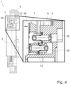
- Fig.4 shows a section of a typical coupling, the section in particular showing a shaft connection 1 for connecting a first shaft 5 and a second shaft 7.
- the second shaft 7 has a first toothing 45 for coupling with a Fig.4 not shown rotor shaft.
- Both shafts are ring-shaped and each comprise a radial area in which both shafts extend.
- the overlapping, radial area is shown in the detailed view in Fig.4 shown enlarged.
- the two shafts are arranged one behind the other and connected by pairs of spring elements, which are distributed in the circumferential direction around the axis of rotation 3.
- Each pair of spring elements comprises a first spring element 11 and a second spring element 13, each of which is designed as a leaf spring, for example as in Figures 1 to 3
- the leaf springs are each attached to the first shaft 5 and to the second shaft 7 via fastening means 35.
- the second shaft 7 is shown in a first axial position in which the spring elements are not deflected and the second shaft 7 is supported by a Fig.4 not shown rotor shaft is decoupled.
- the second shaft 7 can be moved in the axial direction 37, in particular to a second axial position which is further away from the first shaft 5 than the first axial position.
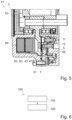
- Fig.5 shows another section of the Fig.4 illustrated clutch 41 with further components of the clutch 41, whereby only one half of the sectional view of the clutch 41 is shown.
- the clutch 41 comprises a housing 51, a rotor shaft 43 and a shaft connection with spring element pairs, a first shaft 5 and a second shaft 7.
- the housing 51 is secured against rotation.
- the rotor shaft 43 can be connected to a shaft of an electric motor (not shown) by means of screws 53, for example.
- the first shaft 5, the second shaft 7 and the rotor shaft 43 are coaxially rotatable about an axis of rotation 3.
- the second shaft 7 has, on the side of the second shaft 7 facing the rotor shaft 43, a first toothing 45 for engagement with a second toothing 47 of the rotor shaft 43.
- Fig.5 shows the second shaft 7 in a first axial position in which the spring elements are unloaded.
- the clutch 41 further comprises an electromagnet 49 with magnetic coils 50.
- the electromagnet 49 is designed to cause a magnetic force on the second shaft 7 when the magnetic coils 50 are energized, so that the second shaft 7 is pulled against the restoring force of the spring elements in the direction of the rotor shaft 43 into a second axial position in which the first toothing 45 of the second shaft 7 engages the second toothing 47 of the rotor shaft.
- the electromagnet closes a magnetic circuit through the housing 51, the rotor shaft 43 and the second shaft 7.
- Fig.6 shows a flow chart of a use 100 of a clutch 41, such as in Fig.5 shown.
- the second shaft 7 is moved in a first axial direction to couple the first shaft 5 and the second shaft 7 to the rotor shaft 43.
- the electromagnet 49 energized.
- the second shaft 7 is pulled by the magnetic force of the electromagnet 49 from a first axial position on the first shaft 5 into a second axial position, whereby the spring element pairs are preloaded without play.
- the first toothing 45 of the second shaft 7 engages with the second toothing 47 of the rotor shaft 43. With the engagement of the toothings, the first shaft 5, the second shaft 7 and the rotor shaft 43 are coupled without play and in a torsionally rigid manner in both directions of rotation.
- the second shaft 7 is moved in a second axial direction different from the first axial direction to decouple the first shaft 5 and the second shaft 7 from the rotor shaft 43.
- the current supply to the electromagnet 49 is switched off.
- the spring element pairs pull the second shaft back into the first axial position, whereby the first gear is disengaged from the second gear 47.
- the rotor shaft 43 is decoupled from the first shaft 5 and the second shaft 7.
- the clutch 41 of the Fig.5 has a "fail-safe" function, in which the rotor shaft 43 is decoupled from the first shaft 5 and the second shaft 7 if the electromagnet 49 fails or switches off.
Landscapes
- Engineering & Computer Science (AREA)
- General Engineering & Computer Science (AREA)
- Mechanical Engineering (AREA)
- Automation & Control Theory (AREA)
- Aviation & Aerospace Engineering (AREA)
- Braking Arrangements (AREA)
- Springs (AREA)
Applications Claiming Priority (1)
| Application Number | Priority Date | Filing Date | Title |
|---|---|---|---|
| DE102023101673.3A DE102023101673A1 (de) | 2023-01-24 | 2023-01-24 | Wellenverbindung |
Publications (1)
| Publication Number | Publication Date |
|---|---|
| EP4407204A1 true EP4407204A1 (fr) | 2024-07-31 |
Family
ID=89707737
Family Applications (1)
| Application Number | Title | Priority Date | Filing Date |
|---|---|---|---|
| EP24153377.7A Pending EP4407204A1 (fr) | 2023-01-24 | 2024-01-23 | Liaison d'arbre |
Country Status (3)
| Country | Link |
|---|---|
| US (1) | US12420912B2 (fr) |
| EP (1) | EP4407204A1 (fr) |
| DE (1) | DE102023101673A1 (fr) |
Citations (6)
| Publication number | Priority date | Publication date | Assignee | Title |
|---|---|---|---|---|
| DE10051587A1 (de) * | 1999-11-08 | 2001-05-10 | Luk Lamellen & Kupplungsbau | Getriebe |
| DE10046440A1 (de) * | 2000-01-05 | 2002-03-28 | Carlos Epelde Lizarazu | Einseitige Kupplung |
| JP2007314133A (ja) * | 2006-05-29 | 2007-12-06 | Jtekt Corp | 輪軸及び台車 |
| DE102013226053A1 (de) * | 2013-12-16 | 2015-06-18 | Volkswagen Aktiengesellschaft | Verbindungselement |
| US20200096049A1 (en) * | 2017-03-22 | 2020-03-26 | Valeo Embrayages | Device for compensating for axial play |
| WO2020128403A1 (fr) | 2018-12-21 | 2020-06-25 | Safran Electronics & Defense | Dispositif d'application d'effort pour un manche de pilotage d'un aéronef |
Family Cites Families (1)
| Publication number | Priority date | Publication date | Assignee | Title |
|---|---|---|---|---|
| US7097019B2 (en) * | 2004-09-01 | 2006-08-29 | Magna Powertrain Usa, Inc. | Low power modulating clutch control system with electromagnetic actuator |
-
2023
- 2023-01-24 DE DE102023101673.3A patent/DE102023101673A1/de active Pending
-
2024
- 2024-01-23 US US18/420,029 patent/US12420912B2/en active Active
- 2024-01-23 EP EP24153377.7A patent/EP4407204A1/fr active Pending
Patent Citations (6)
| Publication number | Priority date | Publication date | Assignee | Title |
|---|---|---|---|---|
| DE10051587A1 (de) * | 1999-11-08 | 2001-05-10 | Luk Lamellen & Kupplungsbau | Getriebe |
| DE10046440A1 (de) * | 2000-01-05 | 2002-03-28 | Carlos Epelde Lizarazu | Einseitige Kupplung |
| JP2007314133A (ja) * | 2006-05-29 | 2007-12-06 | Jtekt Corp | 輪軸及び台車 |
| DE102013226053A1 (de) * | 2013-12-16 | 2015-06-18 | Volkswagen Aktiengesellschaft | Verbindungselement |
| US20200096049A1 (en) * | 2017-03-22 | 2020-03-26 | Valeo Embrayages | Device for compensating for axial play |
| WO2020128403A1 (fr) | 2018-12-21 | 2020-06-25 | Safran Electronics & Defense | Dispositif d'application d'effort pour un manche de pilotage d'un aéronef |
Also Published As
| Publication number | Publication date |
|---|---|
| US12420912B2 (en) | 2025-09-23 |
| DE102023101673A1 (de) | 2024-07-25 |
| US20240246659A1 (en) | 2024-07-25 |
Similar Documents
| Publication | Publication Date | Title |
|---|---|---|
| EP2326853B1 (fr) | Dispositif d'actionnement pour double embrayage | |
| EP2201258A1 (fr) | Système d'actionnement d'embrayage | |
| DE102020210860A1 (de) | Mehrteilige Feder für eine Kugelumlaufspindel | |
| DE102015007280A1 (de) | Fahrzeuglenkung mit Steer-by-Wire-System und mechanischer Rückfallebene | |
| EP2882974B1 (fr) | Élément d'actionnement compensateur d'usure pour embrayage | |
| DE102015205574A1 (de) | Doppelkupplung | |
| EP3123050B1 (fr) | Dispositif de rattrapage de jeu à commande proportionnelle à la course | |
| EP3710356B1 (fr) | Élement méchanique de blocage de retour avec élement d'atténuation | |
| EP2142818B1 (fr) | Embrayage a surfaces de friction | |
| EP4459149A1 (fr) | Embrayage électromagnétique et procédé de fermeture et d'ouverture d'un embrayage électromagnétique | |
| EP2066914B1 (fr) | Entraînement sans jeu pour un dispositif de freinage électromagnétique | |
| WO2012072394A1 (fr) | Actionneur | |
| EP3123051A1 (fr) | Dispositif de rattrapage pour embrayage à friction | |
| EP1862688B1 (fr) | Agencement de transmission d'un couple de rotation pour le conducteur de commande d'un véhicule | |
| EP3728889B1 (fr) | Unité de transmission de couple et chaîne cinématique | |
| EP2122191B1 (fr) | Systeme de debrayage pour un embrayage a rattrapage d'usure | |
| EP4407204A1 (fr) | Liaison d'arbre | |
| DE102006024276A1 (de) | Elektromagnetisch betätigbare Einheit, insbesondere eine Kupplung/Bremse bzw. Sperre | |
| WO2018036589A1 (fr) | Double ressort enroulé, dispositif de rotation et système devant être actionné | |
| WO2011023393A1 (fr) | Embrayage à friction pour actionnement à l'aide d'un agent de pression apte à l'écoulement | |
| EP1870610A2 (fr) | Système de levier et son procédé de montage | |
| DE102015215030A1 (de) | Nehmerzylinder für eine Betätigungseinrichtung einer Kupplung und Kupplungsanordnung für einen Antriebsstrang eines Kraftfahrzeugs | |
| EP3645905B1 (fr) | Dispositif d'accouplement | |
| EP3123048B1 (fr) | Dispositif de rattrapage à commande proportionnelle à la course pour embrayage à friction | |
| WO2013110257A1 (fr) | Dispositif d'embrayage |
Legal Events
| Date | Code | Title | Description |
|---|---|---|---|
| PUAI | Public reference made under article 153(3) epc to a published international application that has entered the european phase |
Free format text: ORIGINAL CODE: 0009012 |
|
| STAA | Information on the status of an ep patent application or granted ep patent |
Free format text: STATUS: THE APPLICATION HAS BEEN PUBLISHED |
|
| AK | Designated contracting states |
Kind code of ref document: A1 Designated state(s): AL AT BE BG CH CY CZ DE DK EE ES FI FR GB GR HR HU IE IS IT LI LT LU LV MC ME MK MT NL NO PL PT RO RS SE SI SK SM TR |
|
| STAA | Information on the status of an ep patent application or granted ep patent |
Free format text: STATUS: REQUEST FOR EXAMINATION WAS MADE |
|
| 17P | Request for examination filed |
Effective date: 20250127 |