EP4407116A2 - Aufhängesystem für keramikfliesen - Google Patents
Aufhängesystem für keramikfliesen Download PDFInfo
- Publication number
- EP4407116A2 EP4407116A2 EP24154641.5A EP24154641A EP4407116A2 EP 4407116 A2 EP4407116 A2 EP 4407116A2 EP 24154641 A EP24154641 A EP 24154641A EP 4407116 A2 EP4407116 A2 EP 4407116A2
- Authority
- EP
- European Patent Office
- Prior art keywords
- mounting portion
- flap
- mounting
- fitted
- connecting portion
- Prior art date
- Legal status (The legal status is an assumption and is not a legal conclusion. Google has not performed a legal analysis and makes no representation as to the accuracy of the status listed.)
- Granted
Links
Images


Classifications
-
- E—FIXED CONSTRUCTIONS
- E04—BUILDING
- E04F—FINISHING WORK ON BUILDINGS, e.g. STAIRS, FLOORS
- E04F13/00—Coverings or linings, e.g. for walls or ceilings
- E04F13/07—Coverings or linings, e.g. for walls or ceilings composed of covering or lining elements; Sub-structures therefor; Fastening means therefor
- E04F13/072—Coverings or linings, e.g. for walls or ceilings composed of covering or lining elements; Sub-structures therefor; Fastening means therefor composed of specially adapted, structured or shaped covering or lining elements
- E04F13/076—Coverings or linings, e.g. for walls or ceilings composed of covering or lining elements; Sub-structures therefor; Fastening means therefor composed of specially adapted, structured or shaped covering or lining elements characterised by the joints between neighbouring elements, e.g. with joint fillings or with tongue and groove connections
-
- E—FIXED CONSTRUCTIONS
- E04—BUILDING
- E04F—FINISHING WORK ON BUILDINGS, e.g. STAIRS, FLOORS
- E04F13/00—Coverings or linings, e.g. for walls or ceilings
- E04F13/07—Coverings or linings, e.g. for walls or ceilings composed of covering or lining elements; Sub-structures therefor; Fastening means therefor
- E04F13/072—Coverings or linings, e.g. for walls or ceilings composed of covering or lining elements; Sub-structures therefor; Fastening means therefor composed of specially adapted, structured or shaped covering or lining elements
- E04F13/077—Coverings or linings, e.g. for walls or ceilings composed of covering or lining elements; Sub-structures therefor; Fastening means therefor composed of specially adapted, structured or shaped covering or lining elements composed of several layers, e.g. sandwich panels
-
- E—FIXED CONSTRUCTIONS
- E04—BUILDING
- E04F—FINISHING WORK ON BUILDINGS, e.g. STAIRS, FLOORS
- E04F13/00—Coverings or linings, e.g. for walls or ceilings
- E04F13/07—Coverings or linings, e.g. for walls or ceilings composed of covering or lining elements; Sub-structures therefor; Fastening means therefor
- E04F13/08—Coverings or linings, e.g. for walls or ceilings composed of covering or lining elements; Sub-structures therefor; Fastening means therefor composed of a plurality of similar covering or lining elements
- E04F13/0801—Separate fastening elements
- E04F13/0803—Separate fastening elements with load-supporting elongated furring elements between wall and covering elements
- E04F13/081—Separate fastening elements with load-supporting elongated furring elements between wall and covering elements with additional fastening elements between furring elements and covering elements
- E04F13/0816—Separate fastening elements with load-supporting elongated furring elements between wall and covering elements with additional fastening elements between furring elements and covering elements the additional fastening elements extending into the back side of the covering elements
- E04F13/0819—Separate fastening elements with load-supporting elongated furring elements between wall and covering elements with additional fastening elements between furring elements and covering elements the additional fastening elements extending into the back side of the covering elements inserted into grooves in the back side of the covering elements
-
- E—FIXED CONSTRUCTIONS
- E04—BUILDING
- E04F—FINISHING WORK ON BUILDINGS, e.g. STAIRS, FLOORS
- E04F13/00—Coverings or linings, e.g. for walls or ceilings
- E04F13/07—Coverings or linings, e.g. for walls or ceilings composed of covering or lining elements; Sub-structures therefor; Fastening means therefor
- E04F13/08—Coverings or linings, e.g. for walls or ceilings composed of covering or lining elements; Sub-structures therefor; Fastening means therefor composed of a plurality of similar covering or lining elements
- E04F13/0801—Separate fastening elements
- E04F13/0803—Separate fastening elements with load-supporting elongated furring elements between wall and covering elements
- E04F13/081—Separate fastening elements with load-supporting elongated furring elements between wall and covering elements with additional fastening elements between furring elements and covering elements
- E04F13/083—Hooking means on the back side of the covering elements
-
- E—FIXED CONSTRUCTIONS
- E04—BUILDING
- E04F—FINISHING WORK ON BUILDINGS, e.g. STAIRS, FLOORS
- E04F13/00—Coverings or linings, e.g. for walls or ceilings
- E04F13/07—Coverings or linings, e.g. for walls or ceilings composed of covering or lining elements; Sub-structures therefor; Fastening means therefor
- E04F13/08—Coverings or linings, e.g. for walls or ceilings composed of covering or lining elements; Sub-structures therefor; Fastening means therefor composed of a plurality of similar covering or lining elements
- E04F13/0801—Separate fastening elements
- E04F13/0832—Separate fastening elements without load-supporting elongated furring elements between wall and covering elements
- E04F13/0833—Separate fastening elements without load-supporting elongated furring elements between wall and covering elements not adjustable
- E04F13/0835—Separate fastening elements without load-supporting elongated furring elements between wall and covering elements not adjustable the fastening elements extending into the back side of the covering elements
-
- E—FIXED CONSTRUCTIONS
- E04—BUILDING
- E04F—FINISHING WORK ON BUILDINGS, e.g. STAIRS, FLOORS
- E04F13/00—Coverings or linings, e.g. for walls or ceilings
- E04F13/07—Coverings or linings, e.g. for walls or ceilings composed of covering or lining elements; Sub-structures therefor; Fastening means therefor
- E04F13/08—Coverings or linings, e.g. for walls or ceilings composed of covering or lining elements; Sub-structures therefor; Fastening means therefor composed of a plurality of similar covering or lining elements
- E04F13/0862—Coverings or linings, e.g. for walls or ceilings composed of covering or lining elements; Sub-structures therefor; Fastening means therefor composed of a plurality of similar covering or lining elements composed of a number of elements which are identical or not, e.g. carried by a common web, support plate or grid
-
- E—FIXED CONSTRUCTIONS
- E04—BUILDING
- E04F—FINISHING WORK ON BUILDINGS, e.g. STAIRS, FLOORS
- E04F13/00—Coverings or linings, e.g. for walls or ceilings
- E04F13/07—Coverings or linings, e.g. for walls or ceilings composed of covering or lining elements; Sub-structures therefor; Fastening means therefor
- E04F13/08—Coverings or linings, e.g. for walls or ceilings composed of covering or lining elements; Sub-structures therefor; Fastening means therefor composed of a plurality of similar covering or lining elements
- E04F13/0871—Coverings or linings, e.g. for walls or ceilings composed of covering or lining elements; Sub-structures therefor; Fastening means therefor composed of a plurality of similar covering or lining elements having an ornamental or specially shaped visible surface
-
- E—FIXED CONSTRUCTIONS
- E04—BUILDING
- E04F—FINISHING WORK ON BUILDINGS, e.g. STAIRS, FLOORS
- E04F13/00—Coverings or linings, e.g. for walls or ceilings
- E04F13/07—Coverings or linings, e.g. for walls or ceilings composed of covering or lining elements; Sub-structures therefor; Fastening means therefor
- E04F13/08—Coverings or linings, e.g. for walls or ceilings composed of covering or lining elements; Sub-structures therefor; Fastening means therefor composed of a plurality of similar covering or lining elements
- E04F13/088—Coverings or linings, e.g. for walls or ceilings composed of covering or lining elements; Sub-structures therefor; Fastening means therefor composed of a plurality of similar covering or lining elements fixed directly to the wall by means of magnets, hook and loop-type or similar fasteners, not necessarily involving the side faces of the covering element
-
- E—FIXED CONSTRUCTIONS
- E04—BUILDING
- E04F—FINISHING WORK ON BUILDINGS, e.g. STAIRS, FLOORS
- E04F13/00—Coverings or linings, e.g. for walls or ceilings
- E04F13/07—Coverings or linings, e.g. for walls or ceilings composed of covering or lining elements; Sub-structures therefor; Fastening means therefor
- E04F13/08—Coverings or linings, e.g. for walls or ceilings composed of covering or lining elements; Sub-structures therefor; Fastening means therefor composed of a plurality of similar covering or lining elements
- E04F13/09—Coverings or linings, e.g. for walls or ceilings composed of covering or lining elements; Sub-structures therefor; Fastening means therefor composed of a plurality of similar covering or lining elements of elements attached to a common web, support plate or grid
-
- E—FIXED CONSTRUCTIONS
- E04—BUILDING
- E04F—FINISHING WORK ON BUILDINGS, e.g. STAIRS, FLOORS
- E04F13/00—Coverings or linings, e.g. for walls or ceilings
- E04F13/07—Coverings or linings, e.g. for walls or ceilings composed of covering or lining elements; Sub-structures therefor; Fastening means therefor
- E04F13/08—Coverings or linings, e.g. for walls or ceilings composed of covering or lining elements; Sub-structures therefor; Fastening means therefor composed of a plurality of similar covering or lining elements
- E04F13/12—Coverings or linings, e.g. for walls or ceilings composed of covering or lining elements; Sub-structures therefor; Fastening means therefor composed of a plurality of similar covering or lining elements of metal or with an outer layer of metal or enameled metal
- E04F13/123—Coverings or linings, e.g. for walls or ceilings composed of covering or lining elements; Sub-structures therefor; Fastening means therefor composed of a plurality of similar covering or lining elements of metal or with an outer layer of metal or enameled metal with an outer layer imitating natural stone, brick work, tiled surface or the like
-
- E—FIXED CONSTRUCTIONS
- E04—BUILDING
- E04F—FINISHING WORK ON BUILDINGS, e.g. STAIRS, FLOORS
- E04F13/00—Coverings or linings, e.g. for walls or ceilings
- E04F13/07—Coverings or linings, e.g. for walls or ceilings composed of covering or lining elements; Sub-structures therefor; Fastening means therefor
- E04F13/08—Coverings or linings, e.g. for walls or ceilings composed of covering or lining elements; Sub-structures therefor; Fastening means therefor composed of a plurality of similar covering or lining elements
- E04F13/14—Coverings or linings, e.g. for walls or ceilings composed of covering or lining elements; Sub-structures therefor; Fastening means therefor composed of a plurality of similar covering or lining elements stone or stone-like materials, e.g. ceramics concrete; of glass or with an outer layer of stone or stone-like materials or glass
- E04F13/142—Coverings or linings, e.g. for walls or ceilings composed of covering or lining elements; Sub-structures therefor; Fastening means therefor composed of a plurality of similar covering or lining elements stone or stone-like materials, e.g. ceramics concrete; of glass or with an outer layer of stone or stone-like materials or glass with an outer layer of ceramics or clays
-
- E—FIXED CONSTRUCTIONS
- E04—BUILDING
- E04F—FINISHING WORK ON BUILDINGS, e.g. STAIRS, FLOORS
- E04F13/00—Coverings or linings, e.g. for walls or ceilings
- E04F13/07—Coverings or linings, e.g. for walls or ceilings composed of covering or lining elements; Sub-structures therefor; Fastening means therefor
- E04F13/21—Fastening means specially adapted for covering or lining elements
- E04F13/24—Hidden fastening means on the rear of the covering or lining elements
-
- E—FIXED CONSTRUCTIONS
- E04—BUILDING
- E04F—FINISHING WORK ON BUILDINGS, e.g. STAIRS, FLOORS
- E04F13/00—Coverings or linings, e.g. for walls or ceilings
- E04F13/07—Coverings or linings, e.g. for walls or ceilings composed of covering or lining elements; Sub-structures therefor; Fastening means therefor
- E04F13/08—Coverings or linings, e.g. for walls or ceilings composed of covering or lining elements; Sub-structures therefor; Fastening means therefor composed of a plurality of similar covering or lining elements
- E04F13/0864—Coverings or linings, e.g. for walls or ceilings composed of covering or lining elements; Sub-structures therefor; Fastening means therefor composed of a plurality of similar covering or lining elements composed of superposed elements which overlap each other and of which the flat outer surface includes an acute angle with the surface to cover
Definitions
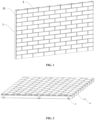
- the present invention relates to a building brick installation system, particularly to a ceramic tile hanging system.
- Ceramic tiles are typically produced by high-temperature firing with a blend of high-quality clay, purple sand clay, and other materials. In comparison to traditional clay bricks, ceramic tiles exhibit a finer texture, more stable color, and graceful lines. They represent an energy-efficient novel building facade material, free from pollution, environmentally friendly, lightweight, high-strength, corrosion-resistant, with good seismic and freeze resistance, sound insulation, and noise reduction capabilities. This seamlessly integrates traditional ceramic culture with modern architecture, meeting the nation's energy efficiency requirements.
- the purpose of this invention is to provide a low-cost ceramic tile hanging system with a simple hanging structure that can stably provide hanging force.
- the present invention provides a ceramic tile hanging system that effectively addresses the aforementioned issues.
- the present invention is implemented as follows:
- a ceramic tile hanging system includes mounting components and ceramic tiles.
- the mounting components are fixed on an installation surface, including several fitting members extending upward from the top surface of the mounting components.
- the fitting members are integrated with the mounting components.
- the ceramic tiles are attached to the mounting components, with the tiles mutually adhering to the side surfaces.
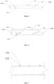
- Each of the tiles is provided an inclined groove, and the inclined groove is hung on and attached to the fitting members.
- the inclined groove includes a first mounting portion opened on the side away from the ceramic tile decorative surface, and a flap mounting portion extending from the side of the first mounting portion.
- Each of the fitting members includes a first connecting portion extending upward from the mounting components, the first connecting portion abutting against the first mounting portion. Furthermore, a connecting flap is attached to the side of the first connecting portion, and the connecting flap is fitted into the flap mounting portion.
- the inclined groove also includes a second mounting portion extending from the end of the first mounting portion towards the interior of the ceramic tile.
- the fitting members also include a second connecting portion extending from the end of the first connecting portion and located within the second mounting portion.
- the first mounting portion is inclined, the flap mounting portion is in communication with the first mounting portion and is level with the horizontal plane.
- the first connecting portion is fitted into the first mounting portion, and the connecting flap is fitted into the flap mounting portion and is level with the horizontal plane.
- the first mounting portion is inclined.
- the flap mounting portion is communicated with a lateral of the first mounting portion and is inclined downward.
- the first connecting portion is fitted into the first mounting portion, and the connecting flap is fitted into the flap mounting portion and is inclined downward.
- the first mounting portion is inclined
- the flap mounting portion is communicated with the lateral the first mounting portion and is inclined upward.
- the first connecting portion is fitted into the first mounting portion
- the connecting flap is fitted into the flap mounting portion and is inclined upward.
- the first mounting portion is inclined, the flap mounting portion communicates laterally with the first mounting portion.
- the second mounting portion tilts downward from the end of the first mounting portion, and the first connecting portion is fitted into the first mounting portion.
- the connecting flap is fitted into the flap mounting portion, and the second connecting portion tilts downward and is fitted into the second mounting portion.
- the first mounting portion is inclined, the flap mounting portion is in communication with the lateral of the first mounting portion.
- the second mounting portion tilts upward from the end of the first mounting portion, and the first connecting portion is fitted into the first mounting portion.
- the connecting flap is fitted into the flap mounting portion, and the second connecting portion tilts upward and is fitted into the second mounting portion.
- the first mounting portion is inclined, the flap mounting portion is in communication with a lateral with the first mounting portion.
- the second mounting portion tilts upward from the end of the first mounting portion, and the first connecting portion is fitted into the first mounting portion.
- the two second connecting portions are spaced and fitted into the second mounting portion, and the connecting flap is positioned between the two second connecting portions and fitted into the flap mounting portion.
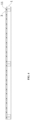
- the mounting components are C-shaped steel, with several fitting members uniformly spaced on the multiple C-shaped steels.
- the C-shaped steel is fixed on the keel, and the keel is fixed on the installation surface.
- the mounting components are mounting baseplates, with several fitting members arranged on the mounting baseplates.
- the mounting baseplate is fixed on the installation surface, or alternatively, the mounting baseplate is fixed on the keel, and the keel is fixed on the installation surface.
- the present invention achieves a secure hanging of ceramic tiles through the design of the inclined groove on the ceramic tile and the fitting members on the mounting elements. Only one inclined groove needs to be created on the ceramic tile. Subsequently, the corresponding mounting portion and the corresponding connecting portion are coordinated by inserting vertically or horizontally. Additionally, there is a flap mounting portion in a different direction from the mounting portion, and the flap mounting portion corresponds to a connecting flap. Different fixing nodes are set in two directions, allowing for a stable and straightforward hanging of ceramic tiles.
- workers can expedite installation by stacking layer by layer of ceramic tiles. The speed of both installation and disassembly is significantly increased. Moreover, due to the simplicity of the hanging structure, the overall cost is substantially reduced, making it more competitive in the market.
- a ceramic tile hanging system comprises: mounting components 1 fixed on the installation surface, including several fitting members 11 extending upward from the top surface of the mounting components 1.
- the fitting members are integrated with the mounting components 1.
- Ceramic tiles 3 are attached to the mounting components 1, with the tiles 3 mutually adhering to the side surfaces.
- Each of the tiles 3 is provided with an inclined groove 31, and the inclined groove 31 is hung on and attached to the fitting members 11.
- the inclined groove 31 includes a first mounting portion 311 opened on the side away from a decorative surface of each of the tiles 3, and a flap mounting portion 312 extending from the side of the first mounting portion 311.
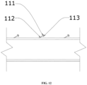
- Each of the fitting members 11 includes a first connecting portion 111 extending upward from the mounting components 1.
- the first connecting portion 111 is abutted against the first mounting portion 311.
- a connecting flap 112 is attached to the side of the first connecting portion 111, and the connecting flap 112 is fitted into the flap mounting portion 312.
- the mounting components 1 can be directly installed on a conventional keel, and in some uneven installation surfaces, such as in brick wall structures with uneven surfaces due to the absence of concrete coating, the surface is uneven, making it difficult to fix the keel. In such cases, the mounting components 1 can be directly fixed to the uneven installation surface without the need for a keel transition, making the installation more flexible.
- the ceramic tiles 3 can be hung vertically or horizontally by adjusting the positions of the corresponding fitting members 11. Depending on user requirements, workers can change the installation direction.
- the fitting members 11 do not need to be individually welded to the mounting components 1 or fixed on the mounting components 1. Instead, they are an integral part of the mounting components 1.
- the mounting components 1 in this embodiment may be a conventional structure.
- the manufacturer can assemble the fitting members 11 according to the requirements of the building facade to be assembled, such as the spacing between the tiles that will be known in advance.
- the specific layout position of the fitting members 11 is determined.
- the shape of the fitting members 11 is cut by a cutting machine, and then the fitting members 11 are rolled into a shape suitable for the tile hanging groove through a roll forming machine. Therefore, when the hanging components are transported to the site, they can be used immediately without the need for on-site processing by craftsmen.
- the ceramic tiles 3 includes outer decorative tile layer 32 and an outer connecting tile layer 33. Both the outer decorative tile layer 32 and the outer connecting tile layer 33 are fired from clay. After being installed as a curtain wall or other decorative surface, their insulation capabilities are well reflected.
- the outer decorative tile layer 32 can be dyed with different colors or carved with different patterns according to its use and the installation environment, without specific limitations.
- the thickness of the outer connecting tile layer 33 should be at least 2-3 cm longer than the inclined groove 31 to ensure the overall strength of the outer connecting tile layer 33.
- the external layer 33 on a single tile 3 is provided with two inclined grooves 31 to ensure the installation strength, ensuring that the hanging elements can provide sufficient hanging force to secure both the outer decorative brick layer 32 and the outer connecting layer 33.
- the inclined grooves 31 is arranged at an angle. If the inclined grooves 31 are simply provided as straight grooves or T-shaped grooves, it would require a change in the structure of the fitting member 11, making the structure of the fitting member 11 complex and thus increasing the cost.
- the tile 3 is not only provided with the inclined first clamping part 111 for hanging but also extends in the other direction from the base of the first clamping part 111, setting up the connecting flap 112. This provides two-directional hanging for the tile 3. Even if interference or deformation occurs in one direction due to external forces, leading to failure, there are still other fixed nodes in different directions to ensure restraint. This additional layer of protection enhances the overall fixation of the tile 3.
- the connecting flap 112 can be positioned at the side of the first connecting portion 111. In fact, the connecting flap 112 can be positioned at a midpoint of the first connecting portion 111 or closer to the groove end. It can also be positioned at the end of the first connecting portion 111. The key is to position it opposite to the extension position of the first connecting portion 111.
- the inclined groove 31 also includes a second mounting portion 313 extending from the end of the first mounting portion 311 into the interior of the ceramic tile 3.
- the fitting member 11 further includes a second connecting portion 113 extending from the end of the first connecting portion 111 and located within the second mounting portion 313. By providing the second connecting portion 113 to extend inward, the second connecting portion 113 provides additional directional fixation on top of the first connecting portion 111. Thus, three points and two directions of fixation are formed, providing an overall fixation effect similar to a complex hanging structure but superior in terms of disassembly, assembly speed, and cost control.
- the coordination between the ceramic tile 3 and the mounting component 1 in this embodiment fully utilizes mechanical hanging, connecting, abutting, and fitting attachment methods.
- the entire hanging process does not involve the use of bolts. Even when installed at a higher height, workers can easily perform the installation without the need for lengthy stays for bolt locking operations.
- the entire process does not use adhesives or glue, avoiding difficulties in disassembly due to the fixed effect of glue during replacement.
- a tile 3 if a tile 3 needs to be replaced, it only requires removing the corresponding vertical column of tiles 3 layer by layer from above or sideways and then sequentially fitting complete tiles 3.
- the tiles 3 are stacked layer by layer in the vertical direction, secured by fitting members 11 one by one.
- the fitting members 11 fix the tiles 3 layer by layer, while horizontally, the tiles 3 abuts to each other, forming a tight structure that squeezes against each other.
- the tiles 3 are fixed horizontally by fitting members 11, and vertically, the tiles 3 abuts to each other.
- the beauty seams are directly implemented through the ceramic tile body.
- the outer decorative tile layer 32 and the outer connecting tile layer 33 are integrally formed.
- the outer connecting tile layer 33 is at least partially longer than the outer decorative tile layer 32, with the excess portion serving as one side of the beauty seam.
- the coordinating block 3321 extending from the outer connecting tile layer 33, while clamped in the coordinating groove 3322, has a relatively wide width. After being clamped into the coordinating groove 3322, part of it still remains exposed, serving as the other side of the beauty seam.
- the seams between adjacent tiles thus form beauty seams on all four sides without the need for a separate beauty seam construction structure and steps, achieving beauty seams through self-formation.
- the settings of the installation portions in the inclined groove 31 and the settings of the connecting portions and connecting flaps 112 in the fitting members 11 will be adaptively adjusted. Specific adjustments are made for various embodiments. First, the situation where there is no second connecting portion 113 in the fitting member 11 is considered.
- the first mounting portion 311 is inclined, and the flap mounting portion 312 is in communication with and level with the horizontal plane of the first mounting portion 311.
- the first connecting portion 111 fits into the first mounting portion 311, and the connecting flap 112 fits into the flap mounting portion 312 and is level with the horizontal plane.
- the connecting flaps 112 are horizontally installed, providing overall structural stability.
- the extension direction is level with the base of the entire tile 3. This configuration ensures that external forces from both the front and back can be evenly distributed, providing a stable tension force.
- both the flap mounting portion 312 and the connecting flap 112 are set downward.
- the first mounting portion 311 is inclined
- the flap mounting portion 312 is in communication with the first mounting portion 311 and is inclined downward
- the first connecting portion 111 fits into the first mounting portion 311
- the connecting flap 112 fits into the flap mounting portion 312 and is inclined downward.
- the connecting flaps 112, set in the same direction, and the outwardly projecting flap mounting portions 312 can firmly hook onto the tile, providing a reliable tension effect even for heavier tiles.
- both the flap mounting portion 312 and the connecting flap 112 are set upward.
- the first mounting portion 311 is inclined
- the flap mounting portion 312 is in communication with the first mounting portion 311 and is inclined upward
- the first connecting portion 111 fits into the first mounting portion 311
- the connecting flap 112 fits into the flap mounting portion 312 and is inclined upward, allowing the first connecting portion 111 and the connecting flap 112 to form a Chinese character "A" shape, achieving the same effect as in Embodiment 1.
- the inclined groove 31 is only provided with the first mounting portion 311 and the flap mounting portion 312, and the fitting member 11 is only provided with the first connecting portion 111 and the connecting flap 112.
- This may be suitable for thinner and lighter tiles 3.
- the two layers of fixation may not be sufficient.
- Due to the increased thickness a second mounting portion 313 is provided that extends inwardly on the tile 3, and a second connecting portion 113 is provided that extends from the first connecting portion 111. This provides three-point fixation for thicker and heavier tiles 3.
- the difference from Embodiments 1-3 is that a second mounting portion 313 and a second connecting portion 113 are provided.
- the first mounting portion 311 is inclined
- the flap mounting portion 312 is in communication with the first mounting portion 311 laterally
- the second mounting portion 313 inclines downward from the end of the first mounting portion 311
- the first connecting portion 111 fits into the first mounting portion 311
- the connecting flap 112 fits into the flap mounting portion 312
- the second connecting portion 113 inclines downward and fits into the second mounting portion 313.
- the lateral lines of the first connecting portion 111 are fixed in combination with the fixation on the opposite side of the connecting flap 112 at the end of the second connecting portion 113, forming a three-point fixation effect for quick and stable installation.
- the difference from Embodiment 4 is that the second connecting portion 113 is inclined upward.
- the first mounting portion 311 is inclined
- the flap mounting portion 312 is laterally connected to the first mounting portion 311
- the second mounting portion 313 inclines upward from the end of the first mounting portion 311
- the first connecting portion 111 fits into the first mounting portion 311
- the connecting flap 112 fits into the flap mounting portion 312
- the second connecting portion 113 inclines upward and fits into the second mounting portion 313.
- the difference from Embodiment 5 is that there are two second connecting portions 113.
- the first mounting portion 311 is inclined
- the flap mounting portion 312 is laterally connected to the first mounting portion 311
- the second mounting portion 313 inclines upward from the end of the first mounting portion 311
- the first connecting portion 111 fits into the first mounting portion 311
- the second connecting portions 113 are spaced apart and clamp inside the second mounting portion 313
- the connecting flap 112 is positioned between the two second connecting portions 113 and fits into the flap mounting portion 312.
- two second connecting portions 113 are set, compared to the original setting of only one second connecting portion 113, providing different fixation nodes in the same direction and setting the connecting flap 112 in the middle of the two second connecting portions 113 to balance the internal structure of the fitting member 11, ensuring the overall fixation effect and extending more fixation nodes.
- the connecting flap 112 in Embodiments 1-6 can be sheet-shaped or arc-shaped, and the position of the connecting flap 112 can also be adjusted according to the installation requirements.
- the mounting member 1 is C-shaped steel 1A, and multiple evenly spaced fitting members 11 are provided on the C-shaped steel 1A.
- the C-shaped steel 1A is secured to the keel frame through the mounting ear plate 2, and the keel frame is secured to the mounting surface.
- the fixing method of C-shaped steel 1A can be used.
- the factory opens the corresponding positions and spacing of the fitting members 11 according to the size of the customer's tile 3, transports them to the site, and directly locks them to the keel frame or the mounting surface. Then, the tiles 3 are hung step by step.
- the style of the opened fitting member 11 can be any style in the above embodiments, and correspondingly, the style of the inclined groove 31 of the tile 3 that cooperates with it can also be any style in the above embodiments, and they can be used in combination.
- the mounting member 1 is an installation base plate 1B.
- the installation base plate 1B is provided with several fitting members 11, and the installation base plate 1B is secured to the mounting surface or the keel frame is secured to the keel frame.
- the location where the tiles 3 need to be hung is a large area of wall, such as needing to hang the entire curtain wall, installing one by one with C-shaped steel 1A is relatively troublesome for workers.
- the hanging effect is the same, both the construction period and the labor cost are increased by more than twice.
- the entire span of the installation base plate 1B can be directly installed on the horizontal and vertical bars of the keel frame, and because of the support of the horizontally and vertically spaced bars, the force on the installation base plate 1B is completely sufficient.
- reinforcement ribs are provided on them to increase the overall strength when C-shaped steel 1A or installation base plate 1B is subjected to shaking force or vibration force.
Landscapes
- Engineering & Computer Science (AREA)
- Architecture (AREA)
- Civil Engineering (AREA)
- Structural Engineering (AREA)
- Chemical & Material Sciences (AREA)
- Ceramic Engineering (AREA)
- Dispersion Chemistry (AREA)
- Finishing Walls (AREA)
Applications Claiming Priority (2)
| Application Number | Priority Date | Filing Date | Title |
|---|---|---|---|
| CN202310082993.0A CN116446568B (zh) | 2023-01-30 | 2023-01-30 | 一种陶砖挂接系统 |
| CN202320156342.7U CN219298544U (zh) | 2023-01-30 | 2023-01-30 | 一种陶砖挂接系统 |
Publications (3)
| Publication Number | Publication Date |
|---|---|
| EP4407116A2 true EP4407116A2 (de) | 2024-07-31 |
| EP4407116A3 EP4407116A3 (de) | 2025-02-19 |
| EP4407116B1 EP4407116B1 (de) | 2025-07-02 |
Family
ID=89771787
Family Applications (1)
| Application Number | Title | Priority Date | Filing Date |
|---|---|---|---|
| EP24154641.5A Active EP4407116B1 (de) | 2023-01-30 | 2024-01-30 | Aufhängesystem für keramikfliesen |
Country Status (2)
| Country | Link |
|---|---|
| US (1) | US20240254776A1 (de) |
| EP (1) | EP4407116B1 (de) |
Families Citing this family (2)
| Publication number | Priority date | Publication date | Assignee | Title |
|---|---|---|---|---|
| EP4407117B1 (de) * | 2023-01-30 | 2026-04-08 | Haoheng (Fujian) Building Materials Technology Co., Ltd. | Aufhängesystem für keramikfliesen |
| CN119593557B (zh) * | 2024-12-05 | 2025-10-31 | 中建深圳装饰有限公司 | 一种装饰板的干挂系统及其安装方法 |
Family Cites Families (6)
| Publication number | Priority date | Publication date | Assignee | Title |
|---|---|---|---|---|
| US3321883A (en) * | 1964-07-06 | 1967-05-30 | Pascucci Michael | Brick veneer support structure |
| JPS60102340U (ja) * | 1983-12-19 | 1985-07-12 | 合名会社 大沢商店 | タイルの支持具 |
| JPH0663337B2 (ja) * | 1987-03-05 | 1994-08-22 | 元旦ビユーティ工業株式会社 | タイルブロツク外装壁 |
| KR101850574B1 (ko) * | 2014-01-22 | 2018-04-19 | (주)엘지하우시스 | 끼움방식 구조를 갖는 마감 처리용 구조물 및 그 시공방법 |
| KR101937711B1 (ko) * | 2017-12-22 | 2019-01-11 | 주식회사 유토플러스 | 마감재 건식시공 시스템 |
| KR102262124B1 (ko) * | 2019-03-15 | 2021-06-08 | 주식회사 유토플러스 | 마감재 건식 시공 시스템 |
-
2024
- 2024-01-30 EP EP24154641.5A patent/EP4407116B1/de active Active
- 2024-01-30 US US18/427,465 patent/US20240254776A1/en active Pending
Also Published As
| Publication number | Publication date |
|---|---|
| US20240254776A1 (en) | 2024-08-01 |
| EP4407116B1 (de) | 2025-07-02 |
| EP4407116A3 (de) | 2025-02-19 |
Similar Documents
| Publication | Publication Date | Title |
|---|---|---|
| EP4407116A2 (de) | Aufhängesystem für keramikfliesen | |
| CN106013585A (zh) | 吊顶跌级装置及安装方法 | |
| CN107419870A (zh) | 一种装饰板干挂系统的施工方法及装饰板干挂系统 | |
| CN109267671A (zh) | 一种室内墙体系统的装修方法 | |
| CN109372176B (zh) | 吊顶及吊顶安装方法 | |
| CN212897326U (zh) | 一种装配式墙面的快速安装结构 | |
| CN210288789U (zh) | 一种快速装配的装配式隔墙安装结构 | |
| CN219298544U (zh) | 一种陶砖挂接系统 | |
| EP4407117B1 (de) | Aufhängesystem für keramikfliesen | |
| CN211899211U (zh) | 吊顶 | |
| CN105971179A (zh) | 灯槽吊顶跌级装置及安装方法 | |
| CN209891542U (zh) | 一种装配式墙体安装组件及墙体 | |
| CN210597833U (zh) | 一种装配式吊顶结构 | |
| CN116427595B (zh) | 一种陶砖挂接系统 | |
| CN211341372U (zh) | 平面吊顶 | |
| CN116446568B (zh) | 一种陶砖挂接系统 | |
| CN215889048U (zh) | 一种墙面板结构 | |
| CN112922220B (zh) | 一种带灯槽的吊顶结构及其施工方法 | |
| CN212957195U (zh) | 一种条缝吸音板的固定部件 | |
| CN212478335U (zh) | 一种无缝保温结构装饰一体化系统 | |
| CN212427740U (zh) | 一种吊顶连接构件 | |
| CN109487924A (zh) | 一种钢框架结构固定下挂式轻质隔板的施工结构及方法 | |
| CN222667456U (zh) | 一种装配式建筑墙体装饰钢结构骨架 | |
| CN206538915U (zh) | 一种陶板竖向大装饰线条的防侧摆系统 | |
| JPH10311113A (ja) | Alc壁パネルの取付構造 |
Legal Events
| Date | Code | Title | Description |
|---|---|---|---|
| PUAI | Public reference made under article 153(3) epc to a published international application that has entered the european phase |
Free format text: ORIGINAL CODE: 0009012 |
|
| STAA | Information on the status of an ep patent application or granted ep patent |
Free format text: STATUS: REQUEST FOR EXAMINATION WAS MADE |
|
| 17P | Request for examination filed |
Effective date: 20240204 |
|
| AK | Designated contracting states |
Kind code of ref document: A2 Designated state(s): AL AT BE BG CH CY CZ DE DK EE ES FI FR GB GR HR HU IE IS IT LI LT LU LV MC ME MK MT NL NO PL PT RO RS SE SI SK SM TR |
|
| PUAL | Search report despatched |
Free format text: ORIGINAL CODE: 0009013 |
|
| AK | Designated contracting states |
Kind code of ref document: A3 Designated state(s): AL AT BE BG CH CY CZ DE DK EE ES FI FR GB GR HR HU IE IS IT LI LT LU LV MC ME MK MT NL NO PL PT RO RS SE SI SK SM TR |
|
| RIC1 | Information provided on ipc code assigned before grant |
Ipc: E04F 13/24 20060101ALI20250113BHEP Ipc: E04F 13/14 20060101ALI20250113BHEP Ipc: E04F 13/12 20060101ALI20250113BHEP Ipc: E04F 13/09 20060101ALI20250113BHEP Ipc: E04F 13/08 20060101ALI20250113BHEP Ipc: E04F 13/077 20060101ALI20250113BHEP Ipc: E04F 13/076 20060101AFI20250113BHEP |
|
| GRAP | Despatch of communication of intention to grant a patent |
Free format text: ORIGINAL CODE: EPIDOSNIGR1 |
|
| STAA | Information on the status of an ep patent application or granted ep patent |
Free format text: STATUS: GRANT OF PATENT IS INTENDED |
|
| INTG | Intention to grant announced |
Effective date: 20250327 |
|
| GRAS | Grant fee paid |
Free format text: ORIGINAL CODE: EPIDOSNIGR3 |
|
| GRAA | (expected) grant |
Free format text: ORIGINAL CODE: 0009210 |
|
| STAA | Information on the status of an ep patent application or granted ep patent |
Free format text: STATUS: THE PATENT HAS BEEN GRANTED |
|
| AK | Designated contracting states |
Kind code of ref document: B1 Designated state(s): AL AT BE BG CH CY CZ DE DK EE ES FI FR GB GR HR HU IE IS IT LI LT LU LV MC ME MK MT NL NO PL PT RO RS SE SI SK SM TR |
|
| REG | Reference to a national code |
Ref country code: GB Ref legal event code: FG4D |
|
| REG | Reference to a national code |
Ref country code: CH Ref legal event code: EP |
|
| REG | Reference to a national code |
Ref country code: DE Ref legal event code: R096 Ref document number: 602024000255 Country of ref document: DE |
|
| REG | Reference to a national code |
Ref country code: IE Ref legal event code: FG4D |
|
| REG | Reference to a national code |
Ref country code: NL Ref legal event code: MP Effective date: 20250702 |
|
| PG25 | Lapsed in a contracting state [announced via postgrant information from national office to epo] |
Ref country code: PT Free format text: LAPSE BECAUSE OF FAILURE TO SUBMIT A TRANSLATION OF THE DESCRIPTION OR TO PAY THE FEE WITHIN THE PRESCRIBED TIME-LIMIT Effective date: 20251103 |
|
| PG25 | Lapsed in a contracting state [announced via postgrant information from national office to epo] |
Ref country code: NL Free format text: LAPSE BECAUSE OF FAILURE TO SUBMIT A TRANSLATION OF THE DESCRIPTION OR TO PAY THE FEE WITHIN THE PRESCRIBED TIME-LIMIT Effective date: 20250702 |
|
| REG | Reference to a national code |
Ref country code: AT Ref legal event code: MK05 Ref document number: 1809408 Country of ref document: AT Kind code of ref document: T Effective date: 20250702 |
|
| PG25 | Lapsed in a contracting state [announced via postgrant information from national office to epo] |
Ref country code: IS Free format text: LAPSE BECAUSE OF FAILURE TO SUBMIT A TRANSLATION OF THE DESCRIPTION OR TO PAY THE FEE WITHIN THE PRESCRIBED TIME-LIMIT Effective date: 20251102 |
|
| PG25 | Lapsed in a contracting state [announced via postgrant information from national office to epo] |
Ref country code: NO Free format text: LAPSE BECAUSE OF FAILURE TO SUBMIT A TRANSLATION OF THE DESCRIPTION OR TO PAY THE FEE WITHIN THE PRESCRIBED TIME-LIMIT Effective date: 20251002 |
|
| REG | Reference to a national code |
Ref country code: LT Ref legal event code: MG9D |
|
| PG25 | Lapsed in a contracting state [announced via postgrant information from national office to epo] |
Ref country code: AT Free format text: LAPSE BECAUSE OF FAILURE TO SUBMIT A TRANSLATION OF THE DESCRIPTION OR TO PAY THE FEE WITHIN THE PRESCRIBED TIME-LIMIT Effective date: 20250702 |
|
| PG25 | Lapsed in a contracting state [announced via postgrant information from national office to epo] |
Ref country code: FI Free format text: LAPSE BECAUSE OF FAILURE TO SUBMIT A TRANSLATION OF THE DESCRIPTION OR TO PAY THE FEE WITHIN THE PRESCRIBED TIME-LIMIT Effective date: 20250702 |
|
| PG25 | Lapsed in a contracting state [announced via postgrant information from national office to epo] |
Ref country code: HR Free format text: LAPSE BECAUSE OF FAILURE TO SUBMIT A TRANSLATION OF THE DESCRIPTION OR TO PAY THE FEE WITHIN THE PRESCRIBED TIME-LIMIT Effective date: 20250702 |
|
| PG25 | Lapsed in a contracting state [announced via postgrant information from national office to epo] |
Ref country code: GR Free format text: LAPSE BECAUSE OF FAILURE TO SUBMIT A TRANSLATION OF THE DESCRIPTION OR TO PAY THE FEE WITHIN THE PRESCRIBED TIME-LIMIT Effective date: 20251003 |
|
| PG25 | Lapsed in a contracting state [announced via postgrant information from national office to epo] |
Ref country code: CZ Free format text: LAPSE BECAUSE OF FAILURE TO SUBMIT A TRANSLATION OF THE DESCRIPTION OR TO PAY THE FEE WITHIN THE PRESCRIBED TIME-LIMIT Effective date: 20250702 Ref country code: SE Free format text: LAPSE BECAUSE OF FAILURE TO SUBMIT A TRANSLATION OF THE DESCRIPTION OR TO PAY THE FEE WITHIN THE PRESCRIBED TIME-LIMIT Effective date: 20250702 |
|
| PG25 | Lapsed in a contracting state [announced via postgrant information from national office to epo] |
Ref country code: LV Free format text: LAPSE BECAUSE OF FAILURE TO SUBMIT A TRANSLATION OF THE DESCRIPTION OR TO PAY THE FEE WITHIN THE PRESCRIBED TIME-LIMIT Effective date: 20250702 |
|
| PG25 | Lapsed in a contracting state [announced via postgrant information from national office to epo] |
Ref country code: BG Free format text: LAPSE BECAUSE OF FAILURE TO SUBMIT A TRANSLATION OF THE DESCRIPTION OR TO PAY THE FEE WITHIN THE PRESCRIBED TIME-LIMIT Effective date: 20250702 Ref country code: PL Free format text: LAPSE BECAUSE OF FAILURE TO SUBMIT A TRANSLATION OF THE DESCRIPTION OR TO PAY THE FEE WITHIN THE PRESCRIBED TIME-LIMIT Effective date: 20250702 |
|
| PG25 | Lapsed in a contracting state [announced via postgrant information from national office to epo] |
Ref country code: RS Free format text: LAPSE BECAUSE OF FAILURE TO SUBMIT A TRANSLATION OF THE DESCRIPTION OR TO PAY THE FEE WITHIN THE PRESCRIBED TIME-LIMIT Effective date: 20251002 |
|
| PG25 | Lapsed in a contracting state [announced via postgrant information from national office to epo] |
Ref country code: ES Free format text: LAPSE BECAUSE OF FAILURE TO SUBMIT A TRANSLATION OF THE DESCRIPTION OR TO PAY THE FEE WITHIN THE PRESCRIBED TIME-LIMIT Effective date: 20250702 |
|
| PG25 | Lapsed in a contracting state [announced via postgrant information from national office to epo] |
Ref country code: SM Free format text: LAPSE BECAUSE OF FAILURE TO SUBMIT A TRANSLATION OF THE DESCRIPTION OR TO PAY THE FEE WITHIN THE PRESCRIBED TIME-LIMIT Effective date: 20250702 |
|
| PG25 | Lapsed in a contracting state [announced via postgrant information from national office to epo] |
Ref country code: DK Free format text: LAPSE BECAUSE OF FAILURE TO SUBMIT A TRANSLATION OF THE DESCRIPTION OR TO PAY THE FEE WITHIN THE PRESCRIBED TIME-LIMIT Effective date: 20250702 |
|
| PG25 | Lapsed in a contracting state [announced via postgrant information from national office to epo] |
Ref country code: IT Free format text: LAPSE BECAUSE OF FAILURE TO SUBMIT A TRANSLATION OF THE DESCRIPTION OR TO PAY THE FEE WITHIN THE PRESCRIBED TIME-LIMIT Effective date: 20250702 |