EP4407100B1 - Unterwasserreinigungsvorrichtung für einen torschlitz und verwendungsverfahren dafür - Google Patents
Unterwasserreinigungsvorrichtung für einen torschlitz und verwendungsverfahren dafür Download PDFInfo
- Publication number
- EP4407100B1 EP4407100B1 EP23169532.1A EP23169532A EP4407100B1 EP 4407100 B1 EP4407100 B1 EP 4407100B1 EP 23169532 A EP23169532 A EP 23169532A EP 4407100 B1 EP4407100 B1 EP 4407100B1
- Authority
- EP
- European Patent Office
- Prior art keywords
- gate slot
- bottom plate
- climbing
- frame
- underwater
- Prior art date
- Legal status (The legal status is an assumption and is not a legal conclusion. Google has not performed a legal analysis and makes no representation as to the accuracy of the status listed.)
- Active
Links
Images
Classifications
-
- B—PERFORMING OPERATIONS; TRANSPORTING
- B08—CLEANING
- B08B—CLEANING IN GENERAL; PREVENTION OF FOULING IN GENERAL
- B08B1/00—Cleaning by methods involving the use of tools
-
- B—PERFORMING OPERATIONS; TRANSPORTING
- B08—CLEANING
- B08B—CLEANING IN GENERAL; PREVENTION OF FOULING IN GENERAL
- B08B1/00—Cleaning by methods involving the use of tools
- B08B1/30—Cleaning by methods involving the use of tools by movement of cleaning members over a surface
-
- B—PERFORMING OPERATIONS; TRANSPORTING
- B08—CLEANING
- B08B—CLEANING IN GENERAL; PREVENTION OF FOULING IN GENERAL
- B08B1/00—Cleaning by methods involving the use of tools
- B08B1/10—Cleaning by methods involving the use of tools characterised by the type of cleaning tool
- B08B1/16—Rigid blades, e.g. scrapers; Flexible blades, e.g. wipers
- B08B1/165—Scrapers
-
- B—PERFORMING OPERATIONS; TRANSPORTING
- B08—CLEANING
- B08B—CLEANING IN GENERAL; PREVENTION OF FOULING IN GENERAL
- B08B13/00—Accessories or details of general applicability for machines or apparatus for cleaning
-
- B—PERFORMING OPERATIONS; TRANSPORTING
- B08—CLEANING
- B08B—CLEANING IN GENERAL; PREVENTION OF FOULING IN GENERAL
- B08B3/00—Cleaning by methods involving the use or presence of liquid or steam
- B08B3/02—Cleaning by the force of jets or sprays
-
- E—FIXED CONSTRUCTIONS
- E02—HYDRAULIC ENGINEERING; FOUNDATIONS; SOIL SHIFTING
- E02B—HYDRAULIC ENGINEERING
- E02B7/00—Barrages or weirs; Layout, construction, methods of, or devices for, making same
- E02B7/20—Movable barrages; Lock or dry-dock gates
- E02B7/26—Vertical-lift gates
- E02B7/28—Vertical-lift gates with sliding gates
-
- E—FIXED CONSTRUCTIONS
- E02—HYDRAULIC ENGINEERING; FOUNDATIONS; SOIL SHIFTING
- E02B—HYDRAULIC ENGINEERING
- E02B8/00—Details of barrages or weirs ; Energy dissipating devices carried by lock or dry-dock gates
- E02B8/02—Sediment base gates; Sand sluices; Structures for retaining arresting waterborne material
- E02B8/023—Arresting devices for waterborne materials
- E02B8/026—Cleaning devices
-
- E—FIXED CONSTRUCTIONS
- E02—HYDRAULIC ENGINEERING; FOUNDATIONS; SOIL SHIFTING
- E02B—HYDRAULIC ENGINEERING
- E02B7/00—Barrages or weirs; Layout, construction, methods of, or devices for, making same
- E02B7/20—Movable barrages; Lock or dry-dock gates
- E02B7/26—Vertical-lift gates
- E02B7/36—Elevating mechanisms for vertical-lift gates
-
- E—FIXED CONSTRUCTIONS
- E02—HYDRAULIC ENGINEERING; FOUNDATIONS; SOIL SHIFTING
- E02F—DREDGING; SOIL-SHIFTING
- E02F3/00—Dredgers; Soil-shifting machines
- E02F3/04—Dredgers; Soil-shifting machines mechanically-driven
- E02F3/88—Dredgers; Soil-shifting machines mechanically-driven with arrangements acting by a sucking or forcing effect, e.g. suction dredgers
- E02F3/90—Component parts, e.g. arrangement or adaptation of pumps
- E02F3/907—Measuring or control devices, e.g. control units, detection means or sensors
-
- Y—GENERAL TAGGING OF NEW TECHNOLOGICAL DEVELOPMENTS; GENERAL TAGGING OF CROSS-SECTIONAL TECHNOLOGIES SPANNING OVER SEVERAL SECTIONS OF THE IPC; TECHNICAL SUBJECTS COVERED BY FORMER USPC CROSS-REFERENCE ART COLLECTIONS [XRACs] AND DIGESTS
- Y02—TECHNOLOGIES OR APPLICATIONS FOR MITIGATION OR ADAPTATION AGAINST CLIMATE CHANGE
- Y02E—REDUCTION OF GREENHOUSE GAS [GHG] EMISSIONS, RELATED TO ENERGY GENERATION, TRANSMISSION OR DISTRIBUTION
- Y02E10/00—Energy generation through renewable energy sources
- Y02E10/20—Hydro energy
Definitions
- the present disclosure relates to the field of water sluice gate cleaning technology, and the present invention is directed towards an underwater cleaning device for a gate slot and its use method thereof.
- a water sluice gate is an important hydraulic structure configured to open or close a water channel
- the water sluice gate mainly comprises a main movable portion, an embedded portion, and a hoisting device.
- the main movable portion is configured to close or open an orifice and is generally known as a sluice gate.
- the embedded portion comprises a main rail, a guide rail, a hinge base, a bottom sill, etc., which are buried around the orifice to form a gate slot for movement of the sluice gate.
- Document CN 112 705 492 A discloses for example an underwater cleaning device.
- debris such as stones, sludge, and construction waste may accumulate into the gate slot during long-term operation of the sluice gate, and therefore the debris needs to be cleaned and erosion pit-holes need to be repaired and patched regularly.
- underwater inspection and cleaning of a sluice gate is mostly done by means of underwater cleaning by a diver or a dredging pump: underwater inspection and cleaning by a diver has strict requirements of water flow velocity and water depth at the gate slot. Under a circumstance that the water flow velocity is fast and the water depth is high, it would be very difficult for a diver to conduct underwater inspection and cleaning, which would have high danger, low efficiency, and limited usage conditions.
- the use of a dredging machine to clean and suck out sediments on the inner wall or bottom of the gate slot in a state of underwater may be affected by multiple factors such as water flow, etc., which would cause the automatic cleaning equipment to tilt during movement along the gate slot, thus the sediment cleaning effect is adversely affected.
- the technical problem to be solved by the present invention is to overcome the defect in the prior art that an automatic cleaning equipment used for gate slot cleaning may be affected by multiple factors such as water flow, etc. in a state of underwater, which would cause the automatic cleaning equipment to tilt during movement along the gate slot and adversely affect the sediment cleaning effect.
- an underwater cleaning device for a gate slot and a use method thereof are provided.
- an underwater cleaning device for a gate slot that comprises:
- the climbing structure further comprises a movable base, a driving wheel is provided on the movable base, and the driving wheel is meshed with a gear rack on one side of a connection plate, and a first power member and a driven wheel are disposed in the movable base, the driving wheel and the driven wheel are respectively arranged on both sides of the connection plate, the driving end of the first power member is rotationally connected to the driving wheel, the driving wheel is rotationally connected to the driven wheel by means of intermediate wheels, and the driven wheel is meshed with a gear rack on the other side of the connection plate.
- the movable base is provided with a first electromagnetic attraction plate component in a direction facing the inner wall of the gate slot
- a fixed base is fixedly provided at one end of the connection plate away from the movable base
- the fixed base is provided with a second electromagnetic attraction plate component in a direction facing the inner wall of the gate slot.
- the frame further comprises transverse braces, the transverse braces are fixedly connected to the vertical braces, and the transverse braces are provided with a camera.
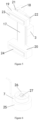
- the horizontal sensor comprises a pedestal, a middle contact ball arranged in the pedestal, and several contacts arranged on an inner wall of the pedestal, the middle contact ball is connected to the pedestal by means of a conductive wire, and the middle contact ball is filled with hydrogen or nitrogen.
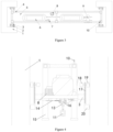
- the lower surface of the bottom plate is provided with at least one second power member and at least one obstacle clearing structure
- the lower surface of the bottom plate is provided with at least one sliding rail along the length direction
- the second power member is configured to drive the obstacle clearing structure to slide along the sliding rail by means of a shifting chain
- the second power member, the obstacle clearing structure and the sliding rail are all arranged in a one-to-one correspondence manner.
- the obstacle clearing structure comprises an obstacle clearing arm and/or a dredging machine, wherein the obstacle clearing arm and/or dredging machine is slidably connected to the sliding rail by means of a shifting base.
- the upper surface of the bottom plate is provided with a sealed cabin and a generator, the controller, a power supply and a signal transceiver are arranged inside the sealed cabin, a surface of the sealed cabin is provided with a control panel, and the generator is connected to the power supply by a wire.
- a method of using an underwater cleaning device for a gate slot wherein a horizontal sensor senses the levelness of a bottom plate in real time in water and transmits the result to a controller, and the controller controls one or more climbing brackets to move up and down along the gate slot to adjust the levelness of the bottom plate.
- the method of using an underwater cleaning device for a gate slot comprises the following steps:
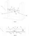
- An underwater cleaning device for a gate slot 1 comprises: a frame, wherein the frame comprises a bottom plate 5 and vertical braces 15 provided at four corners of the bottom plate 5, each vertical brace 15 is provided with a climbing structure, and each of the climbing structures is provided with a climbing bracket 2, the climbing brackets 2 are fixedly connected to the vertical braces 15 by means of connection rods 3, and the climbing brackets 2 are configured to be electromagnetically attracted to an inner wall of the gate slot 1; a horizontal sensor 7 provided on the bottom plate 5; a controller in communicational connection with the horizontal sensor 7 and the climbing brackets 2, wherein, in a state of underwater, the horizontal sensor 7 is configured to sense the levelness of the bottom plate 5 and transmit the result to the controller in real time, the controller is configured to control the climbing brackets 2 to move up and down along the gate slot 1 to maintain the bottom plate 5 in a horizontal state.
- the bottom plate 5 When the frame enters underwater, as affected by multiple factors such as water flow, etc., the bottom plate 5 is not always in a horizontal state.
- the horizontal sensor senses the tilting degree of the bottom plate 5 and transmits the result to the controller, the controller then controls any one or more climbing structures on the vertical braces 15 to make climbing bracket(s) 2 of the one or more climbing structures move up and down along the gate slot 1 to adjust the levelness of the bottom plate 5.
- the climbing bracket(s) 2 After arriving at the corresponding position, the climbing bracket(s) 2 is/are electromagnetically attracted to an inner wall of the gate slot 1 to fix the apparatus to the gate slot 1 to ensure that the apparatus is in a normal operation state so as to achieve ideal sediment cleaning effect.
- a large water flow velocity and a deep water depth there is no need for a diver to enter underwater for inspection or cleaning, so it has the advantages of low danger, high efficiency, and good economic benefits.
- a specific implementation way of the underwater cleaning device for a gate slot 1 comprises: a frame, wherein the frame is provided with a bottom plate 5 and vertical braces 15 fixedly provided at four corners of the bottom plate 5, each vertical brace 15 is connected to a climbing structure by a connection rod, and the climbing structures are configured to be electromagnetically attracted to an inner wall of the gate slot 1.
- the frame is detachably arranged, and the frame consists of a bottom plate 5, vertical braces 15, and transverse braces 4.
- the upper surface of the bottom plate 5 is provided with a generator 9, a second power member 8, sealed cabins 6, and a horizontal sensor 7.
- the lower surface of the bottom plate 5 is provided with an obstacle clearing structure, and the frame has a function of supporting the obstacle clearing structure, the second power member 8, the generator 9, and the sealed cabins 6.
- the horizontal sensor 7 is an electronic contact sensing type level gauge configured to detect the levelness of the bottom plate 5 and the cleaning device.
- the level gauge is composed of a middle contact ball 27 and several contacts 26.
- the middle contact ball 27 is made of a light and thin metal, and its spherical body is connected to a pedestal 25 by a fine conductive wire.
- the middle contact ball 27 is filled with hydrogen, the hydrogen is lighter than air, so that the middle contact ball 27 floats in the air and maintains vertical.
- the middle contact ball 27 would come into contact with one contact 26 on the peripheral edge and thus conduct electricity, then a deflection indication signal is sent to the control system for adjusting the levelness of the bottom plate 5.
- the climbing structure comprises a climbing bracket 2, a connection plate 17 of the climbing bracket 2 is fixedly connected to one of the vertical braces 15 by means of a connection rod 3.
- the climbing structure further comprises a movable base 19, a driving wheel 21 is provided on the movable base 19, and the driving wheel 21 is meshed with a gear rack on one side of the connection plate 17.
- the horizontal sensor 7 senses the tilting degree of the bottom plate 5 and transmits the sensing result to the controller, and after calculation by the controller, the controller then controls any one or more climbing structures on the vertical braces at four corners of the bottom plate 5 according to the calculation result, so as to make climbing bracket(s) 2 of the one or more climbing structures move up and down along the gate slot 1 to adjust the levelness of the bottom plate 5, thereby ensuring that the apparatus is in a normal operation state.
- the climbing structure further comprises a movable base 19 provided at an upper end of the connection plate 17, with a first power member 18, a driving wheel 21, intermediate wheels and a driven wheel 22 disposed in the movable base 19, wherein a drive shaft is disposed between the first power member 18 and the driving wheel 21, the intermediate wheels are disposed between the driving wheel 21 and the driven wheel 22, and the driving wheel 21 and the driven wheel 22 are respectively arranged on both sides of the connection plate 17.
- the first power member 18 comprises a drive motor and a reducer.
- the driving wheel 21, the driven wheel 22 and the intermediate wheels are all gears.
- the front end of the driving wheel 21 is equipped with the first power member 18, while the front end of the driven wheel 22 is not equipped with a power member, using one power member for driving is able to ensure the stability and reliability of torque transmission.
- the drive motor drives the drive shaft to rotate, the drive shaft drives the driving wheel 21 to rotate, and the driving wheel 21 drives the driven wheel 22 to rotate by means of the intermediate wheels.
- the driving wheel 21 and the driven wheel 22 are respectively arranged in the movable base 19 to be in meshing transmission with the gear racks on two sides of the connection plate 17.
- the number of the intermediate wheels is 4, so as to ensure that rotation directions of the driving wheel 21 and the driven wheel 22 are opposite, and ensure that the driving wheel 21 and the driven wheel 22 of the movable base 19 move in an upward or downward direction synchronously on both sides of the connection plate 17.
- the movable base 19 is provided with a first electromagnetic attraction plate component 23 in a direction facing the inner wall of the gate slot 1
- a fixed base 20 is fixedly provided at one end of the connection plate 17 away from the movable base 19.
- the fixed base 20 is fixedly arranged at a lower end of the connection plate 17, and the fixed base 20 is provided with a second electromagnetic attraction plate component 24 in a direction facing the inner wall of the gate slot 1.
- the first electromagnetic attraction plate component 23 comprises a first electromagnetic base plate disposed on the movable base 19, and a first electromagnetic plate disposed on the first electromagnetic base plate.
- the second electromagnetic attraction plate component 24 comprises a second electromagnetic base plate disposed on the movable base 19, and an electromagnetic plate disposed on the second electromagnetic base plate.
- the fixed base 20 is arranged at the lower or upper part of the climbing bracket 2, and the movable base 19 is arranged on the other side of the climbing bracket 2, and the upper and lower positions of the movable base 19 and the fixed base 20 can be exchanged.
- the upper surface of the bottom plate 5 is further provided with two sealed cabins 6, a power supply, the controller, a signal transceiver, an electric energy frequency-conversion frequency modulator and an energy storage device are arranged inside the sealed cabins 6.
- the sealed cabins 6 are connected to the equipment outside the sealed cabins 6 by waterproof joints and cables so as to be able to transmit electrical energy, control instructions and operation data, and the sealed cabins 6 are connected to a control room above water by a towed cable. If a diver performs a diving operation along with the frame, the waterproof control panel on the sealed cabins 6 can also realize underwater on-site operation.
- each of the sliding rails 16 is sleeved with a clamp bracket internally provided with contact rollers, a shifting base 13 is connected under the clamp bracket, and an obstacle clearing structure is connected under the shifting base 13.
- each obstacle clearing structure is provided on one sliding rail 16 separately, so that common rail interference does not occur during operation.
- the bottom plate 5 is provided with second power members 8, the second power members 8 may be a plurality of sets of driving mechanisms, and in principle, each set of the second power members 8 drives one obstacle clearing structure separately, that is, the second power member 8, the obstacle clearing structure and the sliding rail 16 are all arranged in a one-to-one correspondence manner.
- the second power member 8 comprises a walking motor and a reducer gearbox.
- the obstacle clearing structure comprises an obstacle clearing arm 12 and a dredging machine 11, wherein the obstacle clearing structure is moved by the second power member 8 and a driving gear through a shifting chain 14, thereby driving the obstacle clearing arm 12 and the dredging machine 11 to move by means of the clamp bracket and the shifting base attached thereto.
- the obstacle clearing arm 12 and the dredging machine 11 are slidably connected to the sliding rails 16 by the shifting bases 13, and each of the shifting bases 13 is preferably installed in an embedded manner in cooperation with the rail to make each of the shifting bases 13 move back and forth on the rail. According to the number of the obstacle clearing structures, a single-rail or multi-rail arrangement form may be used.
- a generator 9 is further arranged on the frame to supply power for the entire device.
- the generator 9 is connected to the electric energy frequency-conversion frequency modulator, the energy storage device and the power supply inside the sealed cabins 6 by wires.
- cameras 10 are arranged upon the transverse braces 4, and also at an end part of the obstacle clearing arm 12 and at an end part of the dredging machine 11.
- the cameras 10 have functions such as pan-tilt-zoom (PTZ), light supplement and night vision, thereby facilitating timely tracking and omnidirectional observation, and facilitating observation in an environment with poor water quality and poor lighting.
- One of the cameras 10 is arranged upon the transverse braces 4 to generally observe the surrounding environment in a state of underwater.
- some of the cameras 10 are arranged at the end part of the obstacle clearing arm 12 and at the end part of the dredging machine 11 to observe the local environment accurately during working for performing precise operation.
- Signal collected by the cameras 10 is transmitted to the controller in the sealed cabin 6 in a wired manner, and after signal processing by the controller, and then the result is transmitted to the control room above the water surface in a wired manner.
- the instructions sent by the control room are transmitted in a wired manner to ensure the stability of signal transmission.
- video information recognition and analysis is performed by a built-in control software, and automatic recognition, automatic judgement and automatic operation are performed according to work tasks pre-built by personnel, so that the operation mode is simplified, the continuity and reliability of the operation are ensured, and the intelligent level is effectively improved.
- the device of the present patent application may adopt two control modes including a remote master control mode and an on-site control mode, as well as two control manners including an automatic control manner and a manual control manner. That is, the control system is divided into a master control device arranged above the water surface and an on-site control device arranged inside the sealed cabins 6.
- the master control device above the water surface is mainly used for overall control, timely observation, real-time recording and analysis of data and information by an operator with the device of the present patent application. And the master control device may also perform automatic control under the control of a program.
- the on-site control device is mainly used for automatic control, and may also be on-site controlled by an operator who has followed the detection platform to enter underwater when needed.
- standard interchangeable transverse braces 4 or vertical braces 15 are selected for assembling at will, so as to assemble the braces into frames have different lengths and widths for inspection of gate slots 1 with different dimensions.
- the generator 9, etc. installed on the frame is completed, the entire apparatus is first moved to the position at the orifice of the gate slot 1, the energy storage device inside the sealed cabins 6 is used for supplying power.
- the movable base 19 or the fixed base 20 is electromagnetically attracted to or separated from the steel structural members of the gate slot 1, and movement thereof is carried out by synchronous stepwise motions of the movable base 19 and the fixed base 20.
- the fixed base 20 is separated from the gate slot 1 at the same time; or, when the movable base 19 is separated from the gate slot 1, the fixed base 20 is attracted to and fixed on the gate slot 1 at the same time, and in combination with the driving by the first power member 18 via the meshing of gears and gear racks, gradual descension from the orifice of the gate slot 1 is realized.
- the horizontal sensor 7 on the bottom plate 5 is connected to the sealed cabins 6 in a wired manner.
- the middle contact ball 27 of the level gauge comes into contact with one peripheral contact point 26, then a signal is transmitted to the controller inside the sealed cabin 6, and the controller sends the signal to the master control room. After receiving the signal, the console in the control room judges whether the deviation exceeds a tolerance range. If the deviation does not exceed the tolerance range, no deviation adjustment will be made, and if the deviation exceeds the tolerance range, adjustment will be made.
- respective climbing brackets 2 are integrally coordinated and controlled, that is, when movement of the climbing brackets 2 on the opposite side is stopped, the climbing brackets 2 on the lower side is slightly lifted at the same time, that is, the first power member 18 drives the driving wheel 21 and the driven wheel 22 to rotate, so that the connection plate 17 moves upwards and drives the bottom plate 5 on the lower side to move upwards until the levelness of the bottom plate 5 is adjusted to a reasonable range.
- the second power members 8 drive the obstacle clearing arm 12 and the dredging machine 11 to move.
- the obstacle clearing arm 12 and the dredging machine 11 are able to perform multi-dimensional movement and rotation to inspect a vertical surface and a bottom sill surface of the gate slot 1.
- a manipulator of the obstacle clearing arm 12 clamps and clears large block-shaped debris, the large block-shaped debris cleared by the obstacle clearing arm 12 can be took away from an area of the gate slot 1 by water flow, or the large block-shaped debris can be clamped and put into the frame by the obstacle clearing arm 12, and after the cleaning is completed, the large block-shaped debris is brought out of the water surface by the frame for inspection and analysis.
- a base of the manipulator is connected to the obstacle clearing arm 12 by rotational sleeving.
- the dredging machine 11 is configured to flush and clean loose silt and other sediments. When it is necessary to flush and clamp the sediments simultaneously, the obstacle clearing arm 12 and the dredging machine 11 may work together cooperatively for cleaning. At this time, the cameras 10 installed on the obstacle clearing arm 12 and the dredging machine 11 capture images under the control of a program in the controller, and the captured images are automatically recognized by the program.
- the underwater cleaning device for a gate slot 1 has the following advantages: (1) the present patent application has a simple structure and strong adaptability. It can adapt to situations with a large water depth and a high flow rate, and can be used for underwater operation in an unmanned manner or a manned manner. By means of combining standard components, the frame can meet the maintenance needs of various orifice dimensions. It not only can be used for situations of underwater operations, but also can be used for various situations of other hole and groove operations above water; (2) there are various forms of underwater operations that can be undertaken by the device. It can be applied to various underwater dredging situations, as well as various working conditions and needs such as underwater welding, measurement, repair, drilling hole, spraying, etc.
- the electromagnetic attraction climbing brackets 2 have a simple and reliable structure and are very reliable and flexible.
- the electronic contact sensing type level gauge has high sensitivity and strong reliability, and can meet the real-time adjustment needs of the system.
- the manipulator of the obstacle clearing arm 12 can also be an electric drill, a scraper, a spraying gun, etc. to perform refined and complex operations.
- the manipulator which is preferably connected to the obstacle clearing arm 12 by means of rotational sleeving or snap-fitting, can also be replaced with professional repair tools such as an electric drill, a welding gun, a scraper, and a spraying gun for various refined and complex underwater operations.
- the plurality of obstacle clearing structures can also be arranged in a common rail manner.
- the obstacle clearing structure may also adopt a slidable manner without using a sliding rail, such as by using a clamping slot.
- the obstacle clearing structure may also adopt other movement traction manners such as being pulled by a steel wire rope.
- the number of the intermediate wheels can also be another even number such as 2 or 6.
- the number of the sealed cabins 6 can also be 1, 3, 4, or even more.
- the middle contact ball 27 is filled with nitrogen or any other gas with a density lower than air.
Landscapes
- Engineering & Computer Science (AREA)
- General Engineering & Computer Science (AREA)
- Structural Engineering (AREA)
- Mechanical Engineering (AREA)
- Civil Engineering (AREA)
- Barrages (AREA)
Claims (10)
- Unterwasser-Reinigungsvorrichtung für einen Torschlitz, dadurch gekennzeichnet, dass sie umfasst:einen Rahmen, wobei der Rahmen eine Bodenplatte (5) und vertikale Streben (15) umfasst, die an vier Ecken der Bodenplatte (5) vorgesehen sind, wobei jede vertikale Strebe (15) mit einer Kletterstruktur versehen ist und jede der Kletterstrukturen mit einem Kletterhalter (2) versehen ist, wobei die Kletterhalter (2) mittels Verbindungsstangen (3) fest mit den vertikalen Streben (15) verbunden sind und die Kletterhalter (2) so konfiguriert sind, dass sie elektromagnetisch zu einer Innenwand des Torschlitzes (1) angezogen werden;einen horizontalen Sensor (7), der an der Bodenplatte (5) vorgesehen ist;eine Steuerung, die in Kommunikationsverbindung mit dem Horizontalsensor (7) und den Kletterhalterungen (2) steht, wobei der Horizontalsensor (7) so konfiguriert ist, dass er in einem Unterwasserzustand die Ebenheit der Bodenplatte (5) erfasst und das Ergebnis in Echtzeit an die Steuerung überträgt, wobei die Steuerung so konfiguriert ist, dass sie die Kletterhalterungen (2) so steuert, dass sie sich entlang des Torschlitzes (1) auf und ab bewegen, um die Bodenplatte (5) in einem horizontalen Zustand zu halten.
- Die Unterwasser-Reinigungsvorrichtung für einen Torschlitz nach Anspruch 1, dadurch gekennzeichnet, dass die Kletterstruktur ferner eine bewegliche Basis (19) umfasst, ein Antriebsrad (21) auf der beweglichen Basis (19) vorgesehen ist und das Antriebsrad (21) mit einer Zahnstange auf einer Seite einer Verbindungsplatte (17) in Eingriff steht, und ein erstes Antriebselement (18) und ein angetriebenes Rad (22) in der beweglichen Basis (19) angeordnet sind, das Antriebsrad (21) und das angetriebene Rad (22) jeweils auf beiden Seiten der Verbindungsplatte (17) angeordnet sind, das Antriebsende des ersten Antriebselements (18) drehbar mit dem Antriebsrad (21) verbunden ist, das Antriebsrad (21) über Zwischenräder drehbar mit dem angetriebenen Rad (22) verbunden ist und das angetriebene Rad (22) mit einer Zahnstange auf der anderen Seite der Verbindungsplatte (17) in Eingriff steht.
- Die Unterwasser-Reinigungsvorrichtung für einen Torschlitz nach Anspruch 2, dadurch gekennzeichnet, dass die bewegliche Basis (19) mit einer ersten elektromagnetischen Anziehungsplattenkomponente (23) in einer Richtung versehen ist, die der Innenwand des Torschlitzes (1) zugewandt ist, eine feststehende Basis (20) fest an einem Ende der Verbindungsplatte (17) weg von der beweglichen Basis (19) vorgesehen ist, und die feststehende Basis (20) mit einer zweiten elektromagnetischen Anziehungsplattenkomponente (24) in einer Richtung versehen ist, die der Innenwand des Torschlitzes (1) zugewandt ist.
- Die Unterwasser-Reinigungsvorrichtung für einen Torschlitz nach Anspruch 1, dadurch gekennzeichnet, dass der Rahmen weiterhin Querstreben (4) umfasst, wobei die Querstreben (4) fest mit den vertikalen Streben (15) verbunden sind und die Querstreben (4) mit einer Kamera (10) versehen sind.
- Die Unterwasser-Reinigungsvorrichtung für einen Torschlitz nach Anspruch 1, dadurch gekennzeichnet, dass der horizontale Sensor (7) einen Sockel (25), eine in dem Sockel (25) angeordnete mittlere Kontaktkugel (27) und mehrere an einer Innenwand des Sockels (25) angeordnete Kontakte (26) umfasst, die mittlere Kontaktkugel (27) mit dem Sockel (25) über einen leitenden Draht verbunden ist und die mittlere Kontaktkugel (27) mit Wasserstoff oder Stickstoff gefüllt ist.
- Die Unterwasser-Reinigungsvorrichtung für einen Torschlitz nach einem der Ansprüche 1 bis 5, dadurch gekennzeichnet, dass die Unterseite der Bodenplatte (5) mit mindestens einem zweiten Antriebselement (8) und mindestens einer Hindernis-Räumstruktur versehen ist, und die Unterseite der Bodenplatte (5) mit mindestens einer Gleitschiene (16) in Längsrichtung versehen ist, das zweite Antriebselement (8) so konfiguriert ist, dass es die Hindernis-Räumstruktur antreibt, um entlang der Gleitschiene (16) mittels einer Verschiebekette (14) zu gleiten, das zweite Antriebselement (8), die Hindernis-Räumstruktur und die Gleitschiene (16) alle in einer Eins-zu-Eins-Entsprechung angeordnet sind.
- Die Unterwasser-Reinigungsvorrichtung für einen Torschlitz nach Anspruch 6, dadurch gekennzeichnet, dass die Hindernis-Räumstruktur einen Hindernis-Räumarm (12) und/oder eine Baggermaschine (11) umfasst, wobei der Hindernis-Räumarm (12) und/oder die Baggermaschine (11) mittels einer Verschiebebasis (13) verschiebbar mit der Gleitschiene (16) verbunden ist.
- Die Unterwasser-Reinigungsvorrichtung für einen Torschlitz nach Anspruch 6, dadurch gekennzeichnet, dass die Oberseite der Bodenplatte (5) mit einer abgedichteten Kabine (6) und einem Generator (9) versehen ist, dass die Steuerung, eine Stromversorgung und ein Signal-Sende-Empfänger innerhalb der abgedichteten Kabine angeordnet sind, dass eine Oberfläche der abgedichteten Kabine (6) mit einem Bedienfeld versehen ist, und dass der Generator (9) mit der Stromversorgung durch ein Kabel verbunden ist.
- Verfahren zur Verwendung der Unterwasser-Reinigungsvorrichtung für einen Torschlitz nach einem der Ansprüche 1 bis 8, dadurch gekennzeichnet, dass ein horizontaler Sensor die Niveaulage einer Bodenplatte (5) in Echtzeit im Wasser erfasst und das Ergebnis an eine Steuerung überträgt, und die Steuerung eine oder mehrere Kletterhalterungen (2) steuert, die sich entlang des Torschlitzes (1) auf und ab bewegen, um die Niveaulage der Bodenplatte (5) einzustellen.
- Das Verfahren zur Verwendung einer Unterwasser-Reinigungsvorrichtung für einen Torschlitz nach Anspruch 9, dadurch gekennzeichnet, dass es die folgenden Schritte umfasst:Schritt 1, Montage an einer Öffnung des Torschlitzes (1): Auswahl geeigneter Rahmenteile auf der Grundlage der Abmessungen des Torschlitzes (1) und Montage eines Rahmens und von Zubehör auf einer Plattform in der Nähe der Öffnung des Torschlitzes (1), dann Verwendung einer Hebevorrichtung, um die Vorrichtung integral in die Öffnung des Torschlitzes (1) zu heben, und Starten der Vorrichtung, um Energie zuzuführen, so dass die Kletterhalterungen (2) elektromagnetisch zu einer Innenwand des Torschlitzes (1) angezogen werden, um die Vorrichtung integral an der Öffnung des Torschlitzes (1) zu befestigen;Schritt 2, Bewegung in den Torschlitz (1): durch abwechselndes elektromagnetisches Anziehen der befestigten Basen (20) und der beweglichen Basen (19) der jeweiligen Kletterhalterungen (2) an den Torschlitz (1), wobei sich die beweglichen Basen (19) schrittweise bewegen, wodurch der Rahmen allmählich aus der Öffnung des Torschlitzes (1) herabgelassen wird; wobei der an der Bodenplatte (5) des Rahmens angeordnete Horizontalsensor (7) automatisch einen Abweichungswert erfasst und ein Signal an eine Analyse- und Steuervorrichtung überträgt, und wenn der Abweichungswert außerhalb der Toleranz liegt, der Rahmen mittels Feineinstellung durch die Bewegung eines einzelnen Kletterhalters (2) oder einer Vielzahl von Kletterhalterungen (2) auf einen angemessenen Bereich eingestellt und dann mit dem Absenken des Rahmens fortgefahren wird;Schritt 3, Kontrolle und Reinigung der Sedimente: nachdem der Rahmen unter Wasser gelangt ist, sammeln Kameras (10) auf dem Hindernis-Räumarm (12) und der Baggermaschine (11) Videosignale, und mit einem Bilderfassungs- und Erkennungsprogramm, das intern in der Steuerung vorgesehen ist, werden Punkte aus der erfassten Bildkontur genommen, um die erfasste Bildkontur mit einem eingebauten Bild aus einer Bildbibliothek zur Bestimmung zu vergleichen, so dass die Eigenschaften, die Anzahl und das Volumen der Sedimente im Torschlitz (1) angemessen erkannt und beurteilt werden, selbst unter einer Bedingung, dass die Unterwasserwasserqualität trüb ist; die Steuerung den Hindernis-Räumarm (12) und die Baggermaschine (11) steuert, um eine mehrdimensionale Bewegung auszuführen, um den Torschlitz (1) und seine Bodenschwelle zu überprüfen und zu reinigen, der Hindernis-Räumarm (12) große Objektblöcke einklemmt und reinigt, und die Baggermaschine (11) Schlamm spült und reinigt, oder der Hindernis-Räumarm (12) und die Baggermaschine (11) bewegen sich zum gemeinsamen Reinigen an die gleiche Stelle am Boden des Rahmens, der Hindernis-Räumarm (12) ist mit einem Manipulator mittels einer Rotationshülse oder einer Schnappverbindung verbunden, der Manipulator ist eine elektrische Bohrmaschine, eine elektrische Schweißpistole, ein Schaber oder eine Sprühpistole;Schritt 4, Rückführung und Entfernung des Rahmens nach Beendigung der Reinigung: nach Abschluss der Reinigung wird der Rahmen in umgekehrter Reihenfolge wie oben beschrieben in die Öffnung des Torschlitzes (1) gehoben, um den Vorgang abzuschließen.
Applications Claiming Priority (1)
| Application Number | Priority Date | Filing Date | Title |
|---|---|---|---|
| CN202310099206.3A CN116174353A (zh) | 2023-01-30 | 2023-01-30 | 一种门槽水下清理装置及使用方法 |
Publications (2)
| Publication Number | Publication Date |
|---|---|
| EP4407100A1 EP4407100A1 (de) | 2024-07-31 |
| EP4407100B1 true EP4407100B1 (de) | 2025-03-05 |
Family
ID=86185030
Family Applications (1)
| Application Number | Title | Priority Date | Filing Date |
|---|---|---|---|
| EP23169532.1A Active EP4407100B1 (de) | 2023-01-30 | 2023-04-24 | Unterwasserreinigungsvorrichtung für einen torschlitz und verwendungsverfahren dafür |
Country Status (2)
| Country | Link |
|---|---|
| EP (1) | EP4407100B1 (de) |
| CN (1) | CN116174353A (de) |
Families Citing this family (3)
| Publication number | Priority date | Publication date | Assignee | Title |
|---|---|---|---|---|
| CN116577412A (zh) * | 2023-06-13 | 2023-08-11 | 中国电建集团西北勘测设计研究院有限公司 | 一种水电站门槽水下检测装置及方法 |
| CN120250589B (zh) * | 2025-06-04 | 2025-09-09 | 山东省水利科学研究院 | 带淤积监测的自清洁式水利闸门 |
| CN121083708B (zh) * | 2025-11-11 | 2026-02-06 | 辽宁轻工职业学院 | 一种稳定防脱的生产线用运输机械手 |
Family Cites Families (11)
| Publication number | Priority date | Publication date | Assignee | Title |
|---|---|---|---|---|
| AT503924B1 (de) * | 2006-08-18 | 2008-02-15 | Rund Stahl Bau Gmbh & Co | Kletterschalung zum betonieren einer wand eines bauwerks |
| CN102126689B (zh) * | 2010-12-30 | 2012-11-21 | 广东力特工程机械有限公司 | 风力发电机塔筒自动爬升机 |
| CN106269623B (zh) * | 2016-09-06 | 2018-07-06 | 吉林大学 | 一种框架式px泵站水闸门导轨自动清理机 |
| CN207567816U (zh) * | 2017-10-18 | 2018-07-03 | 中国建筑工程(香港)有限公司 | 具有调节支脚的自动摊铺机系统 |
| CN111256660A (zh) * | 2020-01-21 | 2020-06-09 | 合肥京东方视讯科技有限公司 | 一种水平仪及其测量方法 |
| CN112077683B (zh) * | 2020-09-10 | 2024-07-16 | 核电运行研究(上海)有限公司 | 自动爬升打磨涂装一体机 |
| CN112705492B (zh) * | 2020-12-11 | 2023-05-05 | 雷泽松 | 一种可处理污物的水利工程用的水闸清洗装置 |
| CN215003561U (zh) * | 2021-04-25 | 2021-12-03 | 芜湖市轨道(隧道)交通工程质量安全监督站 | 一种水平倾斜检测报警便携式装置 |
| CN113636258B (zh) * | 2021-10-15 | 2021-12-28 | 南通炫昱实业有限公司 | 用于石材雕塑工艺品的人工搬运辅助装置 |
| CN114354746B (zh) * | 2021-12-27 | 2024-05-03 | 江西省天驰高速科技发展有限公司 | 一种桥梁矩形墩柱检测系统及方法 |
| CN217664937U (zh) * | 2022-04-06 | 2022-10-28 | 苏州热工研究院有限公司 | 一种水闸门门槽清理装置 |
-
2023
- 2023-01-30 CN CN202310099206.3A patent/CN116174353A/zh active Pending
- 2023-04-24 EP EP23169532.1A patent/EP4407100B1/de active Active
Also Published As
| Publication number | Publication date |
|---|---|
| EP4407100A1 (de) | 2024-07-31 |
| CN116174353A (zh) | 2023-05-30 |
Similar Documents
| Publication | Publication Date | Title |
|---|---|---|
| EP4407100B1 (de) | Unterwasserreinigungsvorrichtung für einen torschlitz und verwendungsverfahren dafür | |
| CN103672293B (zh) | 一种多维检测两栖作业管道机器人 | |
| CN115889946B (zh) | 一种轮式磁吸附水下焊接系统及其焊接作业方法 | |
| CN112091926A (zh) | 核应急多功能作业机器人 | |
| CN108905008B (zh) | 一种高层建筑物消防系统 | |
| CN109849017B (zh) | 一种变电站机器人挂拆接地线控制系统和控制方法 | |
| CN115201192B (zh) | 一种使用车载机械手臂控制的桥墩检测装置及控制方法 | |
| CN113818345B (zh) | 一种预制型桥墩全方位结构检测及养护平台 | |
| CN115451245A (zh) | 一种水陆两栖排水管道在水检测机器人及其控制方法 | |
| JP2022549421A (ja) | 水門密封面海生物水中清掃設備、設備セット及び清掃方法 | |
| CN111364357B (zh) | 一种可移动道路桥梁检测装置 | |
| CN223211369U (zh) | 一种挂轨式自动巡检机器人 | |
| CN116930216A (zh) | 一种自上线式电力金具无损检测机器人 | |
| DE4415434C2 (de) | Automatische Reinigungsvorrichtung für Fenster- und/oder Fassadenflächen | |
| CN218496775U (zh) | 履带式船体水下检测装置 | |
| CN110640762A (zh) | 一种水利大坝安全巡检机器人 | |
| CN210061146U (zh) | 一种变电站机器人挂拆接地线控制系统 | |
| CN120024428A (zh) | 一种适用于内河航道的空天地一体化移动式管理平台 | |
| CN119715552A (zh) | 一种桥墩表面缺陷检测设备及方法 | |
| WO2020035881A1 (en) | A portable and self-powered device and a system for obstacle identification and removal | |
| CN216680774U (zh) | 一种激光除锈机器人视觉系统 | |
| CN110994424B (zh) | 一种变电设备巡检探测装置 | |
| KR20140081112A (ko) | 해저용 안벽 손상부 디텍터 | |
| CN224184478U (zh) | 一种用于桥梁检测的水下机器人 | |
| CN223443731U (zh) | 无人船释放与回收rov机构 |
Legal Events
| Date | Code | Title | Description |
|---|---|---|---|
| PUAI | Public reference made under article 153(3) epc to a published international application that has entered the european phase |
Free format text: ORIGINAL CODE: 0009012 |
|
| STAA | Information on the status of an ep patent application or granted ep patent |
Free format text: STATUS: REQUEST FOR EXAMINATION WAS MADE |
|
| 17P | Request for examination filed |
Effective date: 20230516 |
|
| AK | Designated contracting states |
Kind code of ref document: A1 Designated state(s): AL AT BE BG CH CY CZ DE DK EE ES FI FR GB GR HR HU IE IS IT LI LT LU LV MC ME MK MT NL NO PL PT RO RS SE SI SK SM TR |
|
| RBV | Designated contracting states (corrected) |
Designated state(s): AL AT BE BG CH CY CZ DE DK EE ES FI FR GB GR HR HU IE IS IT LI LT LU LV MC ME MK MT NL NO PL PT RO RS SE SI SK SM TR |
|
| GRAP | Despatch of communication of intention to grant a patent |
Free format text: ORIGINAL CODE: EPIDOSNIGR1 |
|
| STAA | Information on the status of an ep patent application or granted ep patent |
Free format text: STATUS: GRANT OF PATENT IS INTENDED |
|
| INTG | Intention to grant announced |
Effective date: 20240927 |
|
| GRAS | Grant fee paid |
Free format text: ORIGINAL CODE: EPIDOSNIGR3 |
|
| GRAA | (expected) grant |
Free format text: ORIGINAL CODE: 0009210 |
|
| STAA | Information on the status of an ep patent application or granted ep patent |
Free format text: STATUS: THE PATENT HAS BEEN GRANTED |
|
| AK | Designated contracting states |
Kind code of ref document: B1 Designated state(s): AL AT BE BG CH CY CZ DE DK EE ES FI FR GB GR HR HU IE IS IT LI LT LU LV MC ME MK MT NL NO PL PT RO RS SE SI SK SM TR |
|
| REG | Reference to a national code |
Ref country code: GB Ref legal event code: FG4D |
|
| REG | Reference to a national code |
Ref country code: CH Ref legal event code: EP |
|
| REG | Reference to a national code |
Ref country code: DE Ref legal event code: R096 Ref document number: 602023002274 Country of ref document: DE |
|
| REG | Reference to a national code |
Ref country code: IE Ref legal event code: FG4D |
|
| PG25 | Lapsed in a contracting state [announced via postgrant information from national office to epo] |
Ref country code: RS Free format text: LAPSE BECAUSE OF FAILURE TO SUBMIT A TRANSLATION OF THE DESCRIPTION OR TO PAY THE FEE WITHIN THE PRESCRIBED TIME-LIMIT Effective date: 20250605 |
|
| PG25 | Lapsed in a contracting state [announced via postgrant information from national office to epo] |
Ref country code: FI Free format text: LAPSE BECAUSE OF FAILURE TO SUBMIT A TRANSLATION OF THE DESCRIPTION OR TO PAY THE FEE WITHIN THE PRESCRIBED TIME-LIMIT Effective date: 20250305 |
|
| REG | Reference to a national code |
Ref country code: NL Ref legal event code: MP Effective date: 20250305 |
|
| PG25 | Lapsed in a contracting state [announced via postgrant information from national office to epo] |
Ref country code: ES Free format text: LAPSE BECAUSE OF FAILURE TO SUBMIT A TRANSLATION OF THE DESCRIPTION OR TO PAY THE FEE WITHIN THE PRESCRIBED TIME-LIMIT Effective date: 20250305 |
|
| REG | Reference to a national code |
Ref country code: LT Ref legal event code: MG9D |
|
| PG25 | Lapsed in a contracting state [announced via postgrant information from national office to epo] |
Ref country code: NO Free format text: LAPSE BECAUSE OF FAILURE TO SUBMIT A TRANSLATION OF THE DESCRIPTION OR TO PAY THE FEE WITHIN THE PRESCRIBED TIME-LIMIT Effective date: 20250605 |
|
| PG25 | Lapsed in a contracting state [announced via postgrant information from national office to epo] |
Ref country code: HR Free format text: LAPSE BECAUSE OF FAILURE TO SUBMIT A TRANSLATION OF THE DESCRIPTION OR TO PAY THE FEE WITHIN THE PRESCRIBED TIME-LIMIT Effective date: 20250305 |
|
| PG25 | Lapsed in a contracting state [announced via postgrant information from national office to epo] |
Ref country code: LV Free format text: LAPSE BECAUSE OF FAILURE TO SUBMIT A TRANSLATION OF THE DESCRIPTION OR TO PAY THE FEE WITHIN THE PRESCRIBED TIME-LIMIT Effective date: 20250305 |
|
| PG25 | Lapsed in a contracting state [announced via postgrant information from national office to epo] |
Ref country code: GR Free format text: LAPSE BECAUSE OF FAILURE TO SUBMIT A TRANSLATION OF THE DESCRIPTION OR TO PAY THE FEE WITHIN THE PRESCRIBED TIME-LIMIT Effective date: 20250606 Ref country code: BG Free format text: LAPSE BECAUSE OF FAILURE TO SUBMIT A TRANSLATION OF THE DESCRIPTION OR TO PAY THE FEE WITHIN THE PRESCRIBED TIME-LIMIT Effective date: 20250305 |
|
| PG25 | Lapsed in a contracting state [announced via postgrant information from national office to epo] |
Ref country code: NL Free format text: LAPSE BECAUSE OF FAILURE TO SUBMIT A TRANSLATION OF THE DESCRIPTION OR TO PAY THE FEE WITHIN THE PRESCRIBED TIME-LIMIT Effective date: 20250305 |
|
| PG25 | Lapsed in a contracting state [announced via postgrant information from national office to epo] |
Ref country code: SE Free format text: LAPSE BECAUSE OF FAILURE TO SUBMIT A TRANSLATION OF THE DESCRIPTION OR TO PAY THE FEE WITHIN THE PRESCRIBED TIME-LIMIT Effective date: 20250305 |
|
| PG25 | Lapsed in a contracting state [announced via postgrant information from national office to epo] |
Ref country code: SM Free format text: LAPSE BECAUSE OF FAILURE TO SUBMIT A TRANSLATION OF THE DESCRIPTION OR TO PAY THE FEE WITHIN THE PRESCRIBED TIME-LIMIT Effective date: 20250305 |
|
| PG25 | Lapsed in a contracting state [announced via postgrant information from national office to epo] |
Ref country code: PT Free format text: LAPSE BECAUSE OF FAILURE TO SUBMIT A TRANSLATION OF THE DESCRIPTION OR TO PAY THE FEE WITHIN THE PRESCRIBED TIME-LIMIT Effective date: 20250707 |
|
| PG25 | Lapsed in a contracting state [announced via postgrant information from national office to epo] |
Ref country code: IT Free format text: LAPSE BECAUSE OF FAILURE TO SUBMIT A TRANSLATION OF THE DESCRIPTION OR TO PAY THE FEE WITHIN THE PRESCRIBED TIME-LIMIT Effective date: 20250305 Ref country code: PL Free format text: LAPSE BECAUSE OF FAILURE TO SUBMIT A TRANSLATION OF THE DESCRIPTION OR TO PAY THE FEE WITHIN THE PRESCRIBED TIME-LIMIT Effective date: 20250305 |
|
| PG25 | Lapsed in a contracting state [announced via postgrant information from national office to epo] |
Ref country code: AT Free format text: LAPSE BECAUSE OF FAILURE TO SUBMIT A TRANSLATION OF THE DESCRIPTION OR TO PAY THE FEE WITHIN THE PRESCRIBED TIME-LIMIT Effective date: 20250305 |
|
| PG25 | Lapsed in a contracting state [announced via postgrant information from national office to epo] |
Ref country code: EE Free format text: LAPSE BECAUSE OF FAILURE TO SUBMIT A TRANSLATION OF THE DESCRIPTION OR TO PAY THE FEE WITHIN THE PRESCRIBED TIME-LIMIT Effective date: 20250305 Ref country code: CZ Free format text: LAPSE BECAUSE OF FAILURE TO SUBMIT A TRANSLATION OF THE DESCRIPTION OR TO PAY THE FEE WITHIN THE PRESCRIBED TIME-LIMIT Effective date: 20250305 |
|
| PG25 | Lapsed in a contracting state [announced via postgrant information from national office to epo] |
Ref country code: RO Free format text: LAPSE BECAUSE OF FAILURE TO SUBMIT A TRANSLATION OF THE DESCRIPTION OR TO PAY THE FEE WITHIN THE PRESCRIBED TIME-LIMIT Effective date: 20250305 |
|
| PG25 | Lapsed in a contracting state [announced via postgrant information from national office to epo] |
Ref country code: SK Free format text: LAPSE BECAUSE OF FAILURE TO SUBMIT A TRANSLATION OF THE DESCRIPTION OR TO PAY THE FEE WITHIN THE PRESCRIBED TIME-LIMIT Effective date: 20250305 |
|
| PG25 | Lapsed in a contracting state [announced via postgrant information from national office to epo] |
Ref country code: IS Free format text: LAPSE BECAUSE OF FAILURE TO SUBMIT A TRANSLATION OF THE DESCRIPTION OR TO PAY THE FEE WITHIN THE PRESCRIBED TIME-LIMIT Effective date: 20250705 |
|
| REG | Reference to a national code |
Ref country code: DE Ref legal event code: R119 Ref document number: 602023002274 Country of ref document: DE |
|
| PG25 | Lapsed in a contracting state [announced via postgrant information from national office to epo] |
Ref country code: LU Free format text: LAPSE BECAUSE OF NON-PAYMENT OF DUE FEES Effective date: 20250424 |
|
| PG25 | Lapsed in a contracting state [announced via postgrant information from national office to epo] |
Ref country code: MC Free format text: LAPSE BECAUSE OF FAILURE TO SUBMIT A TRANSLATION OF THE DESCRIPTION OR TO PAY THE FEE WITHIN THE PRESCRIBED TIME-LIMIT Effective date: 20250305 |
|
| REG | Reference to a national code |
Ref country code: BE Ref legal event code: MM Effective date: 20250430 |
|
| PG25 | Lapsed in a contracting state [announced via postgrant information from national office to epo] |
Ref country code: DE Free format text: LAPSE BECAUSE OF NON-PAYMENT OF DUE FEES Effective date: 20251104 |
|
| PLBE | No opposition filed within time limit |
Free format text: ORIGINAL CODE: 0009261 |
|
| STAA | Information on the status of an ep patent application or granted ep patent |
Free format text: STATUS: NO OPPOSITION FILED WITHIN TIME LIMIT |
|
| PG25 | Lapsed in a contracting state [announced via postgrant information from national office to epo] |
Ref country code: DK Free format text: LAPSE BECAUSE OF FAILURE TO SUBMIT A TRANSLATION OF THE DESCRIPTION OR TO PAY THE FEE WITHIN THE PRESCRIBED TIME-LIMIT Effective date: 20250305 |
|
| REG | Reference to a national code |
Ref country code: CH Ref legal event code: L10 Free format text: ST27 STATUS EVENT CODE: U-0-0-L10-L00 (AS PROVIDED BY THE NATIONAL OFFICE) Effective date: 20260114 |
|
| PG25 | Lapsed in a contracting state [announced via postgrant information from national office to epo] |
Ref country code: BE Free format text: LAPSE BECAUSE OF NON-PAYMENT OF DUE FEES Effective date: 20250430 |
|
| 26N | No opposition filed |
Effective date: 20251208 |
|
| PG25 | Lapsed in a contracting state [announced via postgrant information from national office to epo] |
Ref country code: IE Free format text: LAPSE BECAUSE OF NON-PAYMENT OF DUE FEES Effective date: 20250424 |
|
| PG25 | Lapsed in a contracting state [announced via postgrant information from national office to epo] |
Ref country code: FR Free format text: LAPSE BECAUSE OF NON-PAYMENT OF DUE FEES Effective date: 20250505 |