EP4406806A1 - Lokomotiventreibersteuergerät und steuerungsverfahren dafür - Google Patents
Lokomotiventreibersteuergerät und steuerungsverfahren dafür Download PDFInfo
- Publication number
- EP4406806A1 EP4406806A1 EP22891772.0A EP22891772A EP4406806A1 EP 4406806 A1 EP4406806 A1 EP 4406806A1 EP 22891772 A EP22891772 A EP 22891772A EP 4406806 A1 EP4406806 A1 EP 4406806A1
- Authority
- EP
- European Patent Office
- Prior art keywords
- digital
- mechanical
- traction
- brake
- lock
- Prior art date
- Legal status (The legal status is an assumption and is not a legal conclusion. Google has not performed a legal analysis and makes no representation as to the accuracy of the status listed.)
- Withdrawn
Links
- 230000003137 locomotive effect Effects 0.000 title claims abstract description 73
- 238000000034 method Methods 0.000 title claims abstract description 25
- 230000006835 compression Effects 0.000 claims abstract description 9
- 238000007906 compression Methods 0.000 claims abstract description 9
- 230000002159 abnormal effect Effects 0.000 claims description 11
- 238000004891 communication Methods 0.000 claims description 10
- 230000001133 acceleration Effects 0.000 claims description 9
- 230000007613 environmental effect Effects 0.000 claims description 4
- 230000001815 facial effect Effects 0.000 claims description 3
- 230000004044 response Effects 0.000 claims description 3
- 238000011161 development Methods 0.000 description 3
- 230000005856 abnormality Effects 0.000 description 1
- 230000009286 beneficial effect Effects 0.000 description 1
- 230000008859 change Effects 0.000 description 1
- 238000013461 design Methods 0.000 description 1
- 230000000694 effects Effects 0.000 description 1
- 230000003993 interaction Effects 0.000 description 1
- 238000012986 modification Methods 0.000 description 1
- 230000004048 modification Effects 0.000 description 1
- 230000008569 process Effects 0.000 description 1
- 238000012545 processing Methods 0.000 description 1
- 238000004088 simulation Methods 0.000 description 1
- 238000012360 testing method Methods 0.000 description 1
- 238000010977 unit operation Methods 0.000 description 1
- 239000002699 waste material Substances 0.000 description 1
Images


Classifications
-
- B—PERFORMING OPERATIONS; TRANSPORTING
- B61—RAILWAYS
- B61C—LOCOMOTIVES; MOTOR RAILCARS
- B61C17/00—Arrangement or disposition of parts; Details or accessories not otherwise provided for; Use of control gear and control systems
-
- B—PERFORMING OPERATIONS; TRANSPORTING
- B61—RAILWAYS
- B61C—LOCOMOTIVES; MOTOR RAILCARS
- B61C17/00—Arrangement or disposition of parts; Details or accessories not otherwise provided for; Use of control gear and control systems
- B61C17/12—Control gear; Arrangements for controlling locomotives from remote points in the train or when operating in multiple units
-
- B—PERFORMING OPERATIONS; TRANSPORTING
- B61—RAILWAYS
- B61L—GUIDING RAILWAY TRAFFIC; ENSURING THE SAFETY OF RAILWAY TRAFFIC
- B61L15/00—Indicators provided on the vehicle or train for signalling purposes
- B61L15/0063—Multiple on-board control systems, e.g. "2 out of 3"-systems
-
- B—PERFORMING OPERATIONS; TRANSPORTING
- B61—RAILWAYS
- B61L—GUIDING RAILWAY TRAFFIC; ENSURING THE SAFETY OF RAILWAY TRAFFIC
- B61L3/00—Devices along the route for controlling devices on the vehicle or train, e.g. to release brake or to operate a warning signal
- B61L3/02—Devices along the route for controlling devices on the vehicle or train, e.g. to release brake or to operate a warning signal at selected places along the route, e.g. intermittent control simultaneous mechanical and electrical control
- B61L3/08—Devices along the route for controlling devices on the vehicle or train, e.g. to release brake or to operate a warning signal at selected places along the route, e.g. intermittent control simultaneous mechanical and electrical control controlling electrically
- B61L3/12—Devices along the route for controlling devices on the vehicle or train, e.g. to release brake or to operate a warning signal at selected places along the route, e.g. intermittent control simultaneous mechanical and electrical control controlling electrically using magnetic or electrostatic induction; using radio waves
- B61L3/127—Devices along the route for controlling devices on the vehicle or train, e.g. to release brake or to operate a warning signal at selected places along the route, e.g. intermittent control simultaneous mechanical and electrical control controlling electrically using magnetic or electrostatic induction; using radio waves for remote control of locomotives
Definitions
- the present disclosure relates to the technical field of driver controllers, in particular to a locomotive driver controller and a control method thereof.
- locomotive driver controllers used at present are mechanical driver controllers.
- a locomotive driver controller which integrates a digital and intelligent operation apparatus with a mechanical operation apparatus is rare.
- Product digitization and intelligence are inevitable trends in social development, and a driver controller with digital and intelligent operation is an inevitable trend in future development.
- a multifunctional driver controller simulation system (Issue number of Chinese patent CN205750339 ) is constituted by serially connecting an electronic control unit to a rear stage of a universal driver controller.
- functional output of the driver controller for different projects is produced to reduce demands of different projects for different models of driver controllers, costs of system testing, and waste of resources.
- this solution does not integrate mechanical and digital operation functions.
- An objective of the present disclosure is to provide a new generation locomotive driver controller, which integrates a digital and intelligent operation apparatus with a mechanical operation apparatus, has digital and intelligent operation functions, conforms to the development trend of product digitization and intelligence, and also has stable and reliable mechanical operation.
- a locomotive driver controller including a mechanical operation apparatus, the mechanical operation apparatus having a working state and a non-working state, characterized in that the locomotive driver controller further includes a digital operation apparatus, the digital operation apparatus having a working state and a non-working state; the locomotive driver controller further includes an interlocking unit, the interlocking unit includes an interlocking cam connected to the mechanical operation apparatus and an interlocking button connected to the digital operation apparatus, and the interlocking cam and the interlocking button have an interlocking switch release state and an interlocking switch compression state, where when the mechanical operation apparatus is in the working state, the interlocking cam and the interlocking button are in the interlocking switch compression state, and the digital operation apparatus enters the non-working state; and when the mechanical operation apparatus is in the non-working state, the interlocking cam and the interlocking button are in the interlocking switch release state, and the digital operation apparatus is allowed to enter the working state.
- a locomotive driver controller integrating a mechanical operation apparatus and
- the mechanical operation apparatus is mechanical; the mechanical operation apparatus includes a mechanical traction and brake unit, a mechanical direction unit, and a mechanical lock; and the mechanical traction and brake unit and the mechanical direction unit are respectively connected to the mechanical lock in a mechanical interlocking manner.
- the digital operation apparatus is digital; the digital operation apparatus includes a digital lock, a digital direction unit, and a digital traction and brake unit; and the digital direction unit and the digital traction and brake unit are respectively connected to the digital lock in an electrical interlocking manner.
- the mechanical operation apparatus is mechanical, and the digital operation apparatus is digital, so that the locomotive driver controller becomes a new generation locomotive driver controller integrating the digital operation apparatus and the mechanical operation apparatus.
- the digital lock involves one of fingerprint unlocking, password unlocking, facial recognition unlocking, ID card unlocking, and iris unlocking.
- output signals of the mechanical operation apparatus are hard wire signals, and the hard wire signals include a lock signal, a mechanical direction signal, and a traction and brake signal; an output signal of the digital operation apparatus is a communication signal, the communication signal is one of MVB network signal, CAN signal, and Ethernet signal, and the communication signal includes start information, direction information, and traction and brake rate.
- the digital operation apparatus can be remotely controlled by a vehicle monitoring center; and preferably, the remote control is cloud control.
- input of the digital operation apparatus includes one or more of touch screen input, keyboard input, mouse input, and voice input.
- the digital traction and brake unit is used for performing operations according to collected vehicle information.
- the vehicle information includes command information from the vehicle monitoring center, environmental information on a travel path of the locomotive, and locomotive fault information; and the operations performed by the digital traction and brake unit include adjusting locomotive speed, adjusting locomotive acceleration, and applying parking brake.
- the locomotive fault information includes information about abnormal locomotive speed/acceleration, abnormal temperature of locomotive components, and abnormal connection between a pantograph and a contact network.
- a control method for a locomotive driver controller is provided corresponding to the locomotive driver controller.
- a control method for a locomotive driver controller tasks performed by the locomotive driver controller include a mechanical operation task and a digital operation task;
- the mechanical operation task includes a mechanical direction operation, a mechanical traction and brake operation, and a mechanical lock operation;
- the digital operation task includes a digital direction operation, a digital traction and brake operation, and a digital lock operation;
- the response priority of the mechanical operation task is higher than that of the digital operation task; while the mechanical operation task is responded, the digital lock is in a locked state;
- the control method for the locomotive driver controller includes: determining whether the digital lock is locked before performing the digital direction operation or the digital traction and brake operation: and
- control method further includes: determining whether the mechanical lock is in a locked state before performing the mechanical direction operation or the mechanical traction and brake operation:
- both the mechanical operation task and the digital operation task have mark bits, and the mark bits include a zero bit and a non-zero bit;
- the locomotive driver controller includes a mechanical operation apparatus and a digital operation apparatus;
- the mechanical operation apparatus includes a mechanical traction and brake unit used for performing the mechanical traction and brake operation, a mechanical direction unit used for performing the mechanical direction operation, and a mechanical lock;
- the mechanical traction and brake unit and the mechanical direction unit are respectively connected to the mechanical lock in a mechanical interlocking manner;
- the mechanical direction unit when the mechanical lock is in an unlocked position, the mechanical direction unit is allowed to switch to a forward or reverse position, output a corresponding I/O signal and perform a corresponding task, and the mechanical traction and brake unit is allowed to push to a traction position or a brake position from a 0 position, output a corresponding I/O signal and perform a corresponding task.
- the digital direction unit when the digital lock is in an unlocked position, the digital direction unit is allowed to switch to a forward or reverse position, output a corresponding network signal and perform a corresponding task, and the digital traction and brake unit is allowed to switch among a 0 position, a traction position, and a brake position, output a corresponding network signal and perform a corresponding task.
- Beneficial effects achieved by the present invention are as follows: By using the present invention, digital and intelligent operation of a driver controller for a rail transit vehicle can be implemented. Specific effects are as follows:
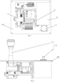
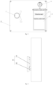
- 100 - panel 10 - mechanical operation apparatus, 11 - mechanical traction and brake unit, 12 - mechanical direction unit, 20 - digital operation apparatus, 21 - digital direction unit, 22 - digital traction and brake unit, 30 - interlocking unit, 31 - interlocking cam, 32 - interlocking button.
- a locomotive driver controller includes a panel 100, as well as a mechanical operation apparatus 10 and a digital operation apparatus 20 integrated on the panel 100.
- the mechanical operation apparatus 10 includes a mechanical traction and brake unit 11, a mechanical direction unit 12, and a mechanical lock (not shown in the figure).
- the mechanical traction and brake unit 11 and the mechanical direction unit 12 are respectively connected to the mechanical lock in a linkage manner.
- the connection in a linkage manner is mechanical interlocking connection of the mechanical traction and brake unit 11 and the mechanical direction unit 12 with the mechanical lock.
- the mechanical traction and brake unit 11 has a working state and a non-working state.
- the digital operation apparatus 20 includes a digital lock (not shown in the figure), a digital direction unit 21, and a digital traction and brake unit 22.
- the digital direction unit 21 and the digital traction and brake unit 22 are respectively connected to the digital lock in a linkage manner.
- the connection in a linkage manner is electrical interlocking connection of the digital traction and brake unit 22 and the digital direction unit 21 with the digital lock.
- the digital traction and brake unit 22 has a working state and a non-working state.
- the locomotive driver controller further includes an interlocking unit 30, the interlocking unit 30 includes an interlocking cam 31 connected to the mechanical operation apparatus 10 and an interlocking button 32 connected to the digital operation apparatus 20, and the interlocking cam 31 and the interlocking button 32 have an interlocking switch release state and an interlocking switch compression state.
- the interlocking cam 31 and the interlocking button 32 are in the interlocking switch compression state, and the digital traction and brake unit 22 enters the non-working state.
- the interlocking cam 31 and the interlocking button 32 are in the interlocking switch release state, and the digital traction and brake unit 22 enters the working state.
- the present invention can implement digital and intelligent operation of the driver controller for a rail transit vehicle.
- the driver controller also has the mechanical operation apparatus, so during the operation of the vehicle, any operation method can be used to control the vehicle.
- output signals of the mechanical operation apparatus can cut off output signals of the digital operation apparatus.
- the mechanical traction and brake unit includes a mechanical handle.
- the mechanical handle that is more intuitive and clearer in hand feel can be quickly operated to avoid braking or accelerating too quickly or too slowly.
- the interlocking cam 31 does not press the interlocking button 32, indicating that the interlocking cam 31 and the interlocking button 32 are in the interlocking switch release state.
- the interlocking cam 31 presses the interlocking button 32, indicating that the interlocking cam 31 and the interlocking button 32 are in the interlocking switch compression state.
- the logic control signal level of the mechanical operation apparatus 10 is higher than the logic control signal level of the digital operation apparatus 20.
- the mechanical operation apparatus 10 is mechanical, and its output signals are hard wire signals.
- the digital operation apparatus 20 is digital, and its output signals are communication signals.
- the communication signals include start information, direction information, and traction and brake rate.
- the output signals of the mechanical operation apparatus 10 are hard wire signals, which include a lock signal, a mechanical direction signal, and a traction and brake signal.
- the output signals of the mechanical operation apparatus are prior to those of the digital operation apparatus.
- operation instructions of the digital operation apparatus for the locomotive may be cut off from mechanical, electrical, and communication aspects.
- the digital operation apparatus 20 of the locomotive driver controller has functions of lock unit operation, direction operation, traction and brake operation, unmanned driving mode, etc.
- the digital lock of the digital operation apparatus 20 is only used for unlocking the digital operation apparatus in a manner of fingerprint unlocking, password unlocking, facial recognition unlocking, iris unlocking, etc., and the specific manner is determined by an actual interface.
- the digital direction unit 21 is a locomotive running direction selection portion, including forward, 0 position, and reverse. According to interface requirements, the digital direction unit may be a touch screen sliding control key or a touch screen button.
- the digital traction and brake unit 22 is a touch screen sliding control, which may display specific values of selected traction speed and brake rate. According to specific requirements of the driver controller, an automatic driving mode button may be added to the interface.
- the communication method of the output signal of the digital operation apparatus 20 involves MVB network signals, which may also be changed to CAN signals or Ethernet network signals according to a specific system.
- the priority of the I/O signals output by the mechanical operation apparatus 10 of the driver controller is higher than that of the network signals such as MVB of the digital operation apparatus 20.
- the mechanical operation apparatus of the driver controller inputs train driver control information, that is, outputs I/O signals, the system controls direction, traction and brake, etc. according to the I/O signals.
- the digital operation apparatus 20 of the driver controller consists of an information input and start unit, a digital direction unit 21, a digital traction and brake unit 22, etc, and each portion has an independent operation area with clear range on a display screen.
- a control method for a locomotive driver controller is proposed corresponding to the locomotive driver controller.
- Tasks performed by the locomotive driver controller include a mechanical operation task and a digital operation task.
- the mechanical operation task includes a mechanical direction operation, a mechanical traction and brake operation, and a mechanical lock operation.
- the digital operation task includes a digital direction operation, a digital traction and brake operation, and a digital lock operation.
- Specific steps of the mechanical operation task include that the mechanical traction and brake unit 11 and the mechanical direction unit 12 are respectively connected to the mechanical lock in a mechanical interlocking manner, and when the mechanical lock is in an unlocked position, the mechanical direction unit 12 is allowed to switch to a forward or reverse position, output a corresponding I/O signal and perform a corresponding task, and the mechanical traction and brake unit 11 is allowed to push to a traction or brake position from a 0 position, output a corresponding I/O signal and perform a corresponding task.
- Specific steps of the digital operation task include that the digital direction unit 21 and the digital traction and brake unit 22 are respectively connected to the digital lock in an electrical interlocking manner, and when the digital lock is unlocked, the digital direction unit 21 is allowed to switch to a forward or reverse position, output a corresponding network signal and perform the corresponding task, and the digital traction and brake unit is allowed to switch among a 0 position, traction position, and brake position, output a corresponding network signal and perform a corresponding task.
- the response priority of the mechanical operation task is higher than that of the digital operation task. While the mechanical operation task is responded, the digital lock is in a locked state.
- the control method for the locomotive driver controller includes: determining whether the mechanical lock is in a locked state before performing the mechanical direction operation or the mechanical traction and brake operation, and interrupting the mechanical operation task if the mechanical lock is in the locked state, or performing the mechanical direction operation or the mechanical traction and brake operation when the mechanical lock is in an unlocked state; and determining whether the digital lock is in a locked state before performing the digital direction operation or the digital traction and brake operation, and interrupting the digital operation task if the digital lock is in the locked state, or performing the digital direction operation or the digital traction and brake operation if the digital lock is in an unlocked state.
- both the mechanical operation task and the digital operation task have mark bits, the mark bits include a zero bit and a non-zero bit, the zero bit represents a non-working state, and the non-zero bit represents a working state.
- the mark bit of the mechanical operation task is zero, it indicates that the mechanical operation task is not performed.
- the mark bit of the mechanical operation task is a non-zero, it indicates that the mechanical operation task is being performed.
- the mark bit of the digital operation task is zero, it indicates that the digital operation task is not performed.
- the mark bit of the digital operation task is non-zero, it indicates that the digital operation task is being performed.
- the mark bit of the mechanical operation task is a non-zero, the digital operation task is not allowed to be performed.
- the mark bit of the mechanical operation task is zero, the digital operation task is performed after the digital lock is unlocked.
- control method further includes the following steps:
- the digital operation apparatus 20 is allowed to be remotely controlled by a vehicle monitoring center.
- the remote control can be cloud control.
- the input of the digital operation apparatus 20 includes one or more of touch screen input, keyboard input, mouse input, and voice input.
- the digital operation apparatus 20 may further receive information collected by vehicle sensors and cameras.
- the digital operation apparatus adopts a human-computer interaction system for operation and control, including but not limited to touch screen input and voice input. Input and display of the digital operation apparatus may be performed on a driver's console main control screen or HUD display (head-up display).
- HUD display head-up display
- the digital traction and brake unit 22 is used for performing operations according to collected vehicle information
- the vehicle information includes command information from the vehicle monitoring center (for example, the vehicle monitoring center indicates the locomotive to accelerate, decelerate, or stop through remote control), environmental information on a travel path of the locomotive, and locomotive fault information.
- the operations performed by the digital traction and brake unit 22 include adjusting locomotive speed, adjusting locomotive acceleration, and applying parking brake.
- the locomotive fault information includes information about abnormal locomotive speed/acceleration, abnormal temperature of locomotive components, and abnormal connection between a pantograph and a contact network.
- the digital operation apparatus may recognize, analyze, and respond to the information collected by the vehicle sensors and cameras to achieve traction and brake control on the vehicle and the like.
- An internal control program of the digital operation apparatus can adjust the control state and change the current traction and brake state according to the external operating environment recognized by the vehicle (such as obstacles) and instructions sent by the vehicle monitoring center.
- the sensors mounted on a front pilot can collect information about obstacles on the travel path of the locomotive.
- the digital traction and brake unit 22 can perform a parking operation.
- the cameras mounted on the vehicle can capture environmental image information (such as obstacles), the vehicle controller can process the image information, and the digital traction and brake unit 22 can perform a corresponding operation (such as adjusting the vehicle speed or acceleration, or even parking) according to the processing results.
- the digital traction and brake unit 22 can also perform a corresponding operation (such as adjusting the vehicle speed or acceleration, or even parking).
Landscapes
- Engineering & Computer Science (AREA)
- Mechanical Engineering (AREA)
- Automation & Control Theory (AREA)
- Transportation (AREA)
- Electric Propulsion And Braking For Vehicles (AREA)
Applications Claiming Priority (2)
| Application Number | Priority Date | Filing Date | Title |
|---|---|---|---|
| CN202111349566.1A CN113879342B (zh) | 2021-11-15 | 2021-11-15 | 一种机车司机控制器及其控制方法 |
| PCT/CN2022/126934 WO2023082975A1 (zh) | 2021-11-15 | 2022-10-24 | 一种机车司机控制器及其控制方法 |
Publications (1)
| Publication Number | Publication Date |
|---|---|
| EP4406806A1 true EP4406806A1 (de) | 2024-07-31 |
Family
ID=79018128
Family Applications (1)
| Application Number | Title | Priority Date | Filing Date |
|---|---|---|---|
| EP22891772.0A Withdrawn EP4406806A1 (de) | 2021-11-15 | 2022-10-24 | Lokomotiventreibersteuergerät und steuerungsverfahren dafür |
Country Status (3)
| Country | Link |
|---|---|
| EP (1) | EP4406806A1 (de) |
| CN (1) | CN113879342B (de) |
| WO (1) | WO2023082975A1 (de) |
Families Citing this family (2)
| Publication number | Priority date | Publication date | Assignee | Title |
|---|---|---|---|---|
| CN113879342B (zh) * | 2021-11-15 | 2022-10-14 | 中车株洲电力机车有限公司 | 一种机车司机控制器及其控制方法 |
| CN119863918B (zh) * | 2025-01-03 | 2025-11-11 | 中车株洲电力机车有限公司 | 用于机车无线遥控模式的解钩控制方法和系统及机车 |
Family Cites Families (17)
| Publication number | Priority date | Publication date | Assignee | Title |
|---|---|---|---|---|
| US6853890B1 (en) * | 2003-09-22 | 2005-02-08 | Beltpack Corporation | Programmable remote control system and apparatus for a locomotive |
| US8292237B1 (en) * | 2005-12-21 | 2012-10-23 | Anthony John Ireland | Control expansion for conventionally powered model railroads |
| CN200988436Y (zh) * | 2006-11-03 | 2007-12-12 | 株洲丰达电力机车配件实业有限责任公司 | 数字式司机控制器 |
| CN100584677C (zh) * | 2007-05-23 | 2010-01-27 | 南车株洲电力机车有限公司 | 一种电子制动控制器控制方法及装置 |
| CN103818394A (zh) * | 2014-03-06 | 2014-05-28 | 南车株洲电力机车有限公司 | 一种电子司机控制装置 |
| CN103863364B (zh) * | 2014-03-27 | 2015-11-18 | 北京清软英泰信息技术有限公司 | 一种基于调度信号的货运机车自动操纵实时优化控制系统 |
| CN104590333B (zh) * | 2014-12-11 | 2016-08-17 | 中国北车集团大连机车研究所有限公司 | 一种铁路列车智能操纵优化控制系统 |
| CN104875753B (zh) * | 2015-06-01 | 2017-05-17 | 南车株洲电力机车有限公司 | 一种司机控制器联锁机构 |
| CN106560368B (zh) * | 2015-10-29 | 2019-03-01 | 上海精研电子科技有限公司 | 一种非接触数字式司机控制器 |
| CN105365851A (zh) * | 2015-12-15 | 2016-03-02 | 中车大连机车研究所有限公司 | 智能机车司机控制装置 |
| CN205750339U (zh) | 2016-06-24 | 2016-11-30 | 南京华士电子科技有限公司 | 多功能司机控制器模拟系统 |
| CN206179703U (zh) * | 2016-11-07 | 2017-05-17 | 中车株洲电力机车有限公司 | 动车组自复位无人警惕装置、牵引制动单元及司机控制器 |
| CN107745718B (zh) * | 2017-10-17 | 2019-10-18 | 西安文理学院 | 一种机车电子编码式司机控制器 |
| CN109910926A (zh) * | 2019-03-22 | 2019-06-21 | 西安开天铁路电气股份有限公司 | 一种具有自复功能的地铁司机控制器 |
| CN210822230U (zh) * | 2019-09-18 | 2020-06-23 | 中车株洲电力机车有限公司 | 机车的牵引制动单元及其司机控制器 |
| CN110816561B (zh) * | 2019-12-17 | 2024-07-23 | 株洲时菱交通设备有限公司 | 一种具有互锁功能的司机控制器 |
| CN113879342B (zh) * | 2021-11-15 | 2022-10-14 | 中车株洲电力机车有限公司 | 一种机车司机控制器及其控制方法 |
-
2021
- 2021-11-15 CN CN202111349566.1A patent/CN113879342B/zh active Active
-
2022
- 2022-10-24 WO PCT/CN2022/126934 patent/WO2023082975A1/zh not_active Ceased
- 2022-10-24 EP EP22891772.0A patent/EP4406806A1/de not_active Withdrawn
Also Published As
| Publication number | Publication date |
|---|---|
| WO2023082975A1 (zh) | 2023-05-19 |
| CN113879342A (zh) | 2022-01-04 |
| CN113879342B (zh) | 2022-10-14 |
Similar Documents
| Publication | Publication Date | Title |
|---|---|---|
| EP4406806A1 (de) | Lokomotiventreibersteuergerät und steuerungsverfahren dafür | |
| CN106891895B (zh) | 一种车辆控制方法及装置 | |
| CN105270407B (zh) | 一种自动驾驶汽车行驶模式切换方法及系统 | |
| CN107943046B (zh) | 一种自动驾驶车辆人机控制权移交方法及系统 | |
| CN106873596A (zh) | 一种车辆控制方法及装置 | |
| CN115700205B (zh) | 一种智能驾驶控制系统及车辆 | |
| CN112622931A (zh) | 平行驾驶中的异常处理方法、自动驾驶车辆及云端驾驶舱 | |
| CN117301877B (zh) | 车辆的控制方法、装置、设备、存储介质以及车辆 | |
| CN109159747A (zh) | 集p档开关和epb开关于一体的集成开关、控制方法及车辆 | |
| CN115891655A (zh) | 用于新能源汽车的动力恢复方法、装置、终端及存储介质 | |
| CN117465503A (zh) | 支持ctcs与cbtc跨制式运行的列车控制方法及列控车载设备 | |
| US12103565B2 (en) | Autonomous vehicle driving device for managing power saving state, autonomous vehicle driving method for managing power saving state, and plurality of non-transitory storage media for managing power saving state | |
| CN107770056A (zh) | 基于微信的车载语音聊天系统及控制方法 | |
| CN110796851A (zh) | 一种共享司机驾驶系统、单车驾驶方法及司机调度方法 | |
| CN113147780A (zh) | 一种自适应巡航系统开关的控制方法及系统 | |
| CN113715825A (zh) | 一种车辆的换挡控制设备、方法及一种车辆 | |
| CN114815658A (zh) | 机车自动驾驶仿真试验系统及方法 | |
| CN118390596A (zh) | 一种基于电控手柄的辅助控制方法、系统及挖掘机 | |
| CN113759804B (zh) | 一种用于车辆远程控制的方法及系统 | |
| CN112486448B (zh) | 驾驶台信息数字化方法、装置及存储介质 | |
| CN111376857A (zh) | 车辆控制方法、装置、电子设备和计算机存储介质 | |
| CN115959150A (zh) | 一种无人驾驶观光车的人机交互系统及方法 | |
| CN115610447A (zh) | 车辆控制方法、装置、设备及存储介质 | |
| CN115294751A (zh) | 一种遥控驾驶方法、系统和电子设备 | |
| CN114967527A (zh) | 基于短距离无线通讯的手机遥控泊车系统 |
Legal Events
| Date | Code | Title | Description |
|---|---|---|---|
| STAA | Information on the status of an ep patent application or granted ep patent |
Free format text: STATUS: THE INTERNATIONAL PUBLICATION HAS BEEN MADE |
|
| PUAI | Public reference made under article 153(3) epc to a published international application that has entered the european phase |
Free format text: ORIGINAL CODE: 0009012 |
|
| STAA | Information on the status of an ep patent application or granted ep patent |
Free format text: STATUS: REQUEST FOR EXAMINATION WAS MADE |
|
| 17P | Request for examination filed |
Effective date: 20240425 |
|
| AK | Designated contracting states |
Kind code of ref document: A1 Designated state(s): AL AT BE BG CH CY CZ DE DK EE ES FI FR GB GR HR HU IE IS IT LI LT LU LV MC ME MK MT NL NO PL PT RO RS SE SI SK SM TR |
|
| STAA | Information on the status of an ep patent application or granted ep patent |
Free format text: STATUS: THE APPLICATION HAS BEEN WITHDRAWN |
|
| 18W | Application withdrawn |
Effective date: 20250109 |