EP4406784A1 - Dichtungsanordnung für einen lastwagen mit einer beweglichen kabine - Google Patents
Dichtungsanordnung für einen lastwagen mit einer beweglichen kabine Download PDFInfo
- Publication number
- EP4406784A1 EP4406784A1 EP23153975.0A EP23153975A EP4406784A1 EP 4406784 A1 EP4406784 A1 EP 4406784A1 EP 23153975 A EP23153975 A EP 23153975A EP 4406784 A1 EP4406784 A1 EP 4406784A1
- Authority
- EP
- European Patent Office
- Prior art keywords
- flange
- sealing assembly
- truck
- cabin
- frame
- Prior art date
- Legal status (The legal status is an assumption and is not a legal conclusion. Google has not performed a legal analysis and makes no representation as to the accuracy of the status listed.)
- Granted
Links
Images


Classifications
-
- B—PERFORMING OPERATIONS; TRANSPORTING
- B62—LAND VEHICLES FOR TRAVELLING OTHERWISE THAN ON RAILS
- B62D—MOTOR VEHICLES; TRAILERS
- B62D35/00—Vehicle bodies characterised by streamlining
- B62D35/001—For commercial vehicles or tractor-trailer combinations, e.g. caravans
-
- B—PERFORMING OPERATIONS; TRANSPORTING
- B60—VEHICLES IN GENERAL
- B60J—WINDOWS, WINDSCREENS, NON-FIXED ROOFS, DOORS, OR SIMILAR DEVICES FOR VEHICLES; REMOVABLE EXTERNAL PROTECTIVE COVERINGS SPECIALLY ADAPTED FOR VEHICLES
- B60J10/00—Sealing arrangements
- B60J10/15—Sealing arrangements characterised by the material
-
- B—PERFORMING OPERATIONS; TRANSPORTING
- B60—VEHICLES IN GENERAL
- B60J—WINDOWS, WINDSCREENS, NON-FIXED ROOFS, DOORS, OR SIMILAR DEVICES FOR VEHICLES; REMOVABLE EXTERNAL PROTECTIVE COVERINGS SPECIALLY ADAPTED FOR VEHICLES
- B60J10/00—Sealing arrangements
- B60J10/20—Sealing arrangements characterised by the shape
- B60J10/21—Sealing arrangements characterised by the shape having corner parts or bends
-
- B—PERFORMING OPERATIONS; TRANSPORTING
- B60—VEHICLES IN GENERAL
- B60J—WINDOWS, WINDSCREENS, NON-FIXED ROOFS, DOORS, OR SIMILAR DEVICES FOR VEHICLES; REMOVABLE EXTERNAL PROTECTIVE COVERINGS SPECIALLY ADAPTED FOR VEHICLES
- B60J10/00—Sealing arrangements
- B60J10/30—Sealing arrangements characterised by the fastening means
- B60J10/32—Sealing arrangements characterised by the fastening means using integral U-shaped retainers
-
- B—PERFORMING OPERATIONS; TRANSPORTING
- B60—VEHICLES IN GENERAL
- B60R—VEHICLES, VEHICLE FITTINGS, OR VEHICLE PARTS, NOT OTHERWISE PROVIDED FOR
- B60R13/00—Elements for body-finishing, identifying, or decorating; Arrangements or adaptations for advertising purposes
- B60R13/08—Insulating elements, e.g. for sound insulation
- B60R13/0838—Insulating elements, e.g. for sound insulation for engine compartments
-
- F—MECHANICAL ENGINEERING; LIGHTING; HEATING; WEAPONS; BLASTING
- F16—ENGINEERING ELEMENTS AND UNITS; GENERAL MEASURES FOR PRODUCING AND MAINTAINING EFFECTIVE FUNCTIONING OF MACHINES OR INSTALLATIONS; THERMAL INSULATION IN GENERAL
- F16J—PISTONS; CYLINDERS; SEALINGS
- F16J15/00—Sealings
- F16J15/02—Sealings between relatively-stationary surfaces
- F16J15/021—Sealings between relatively-stationary surfaces with elastic packing
- F16J15/022—Sealings between relatively-stationary surfaces with elastic packing characterised by structure or material
- F16J15/024—Sealings between relatively-stationary surfaces with elastic packing characterised by structure or material the packing being locally weakened in order to increase elasticity
- F16J15/027—Sealings between relatively-stationary surfaces with elastic packing characterised by structure or material the packing being locally weakened in order to increase elasticity and with a hollow profile
-
- F—MECHANICAL ENGINEERING; LIGHTING; HEATING; WEAPONS; BLASTING
- F16—ENGINEERING ELEMENTS AND UNITS; GENERAL MEASURES FOR PRODUCING AND MAINTAINING EFFECTIVE FUNCTIONING OF MACHINES OR INSTALLATIONS; THERMAL INSULATION IN GENERAL
- F16J—PISTONS; CYLINDERS; SEALINGS
- F16J15/00—Sealings
- F16J15/02—Sealings between relatively-stationary surfaces
- F16J15/06—Sealings between relatively-stationary surfaces with solid packing compressed between sealing surfaces
- F16J15/062—Sealings between relatively-stationary surfaces with solid packing compressed between sealing surfaces characterised by the geometry of the seat
-
- B—PERFORMING OPERATIONS; TRANSPORTING
- B62—LAND VEHICLES FOR TRAVELLING OTHERWISE THAN ON RAILS
- B62D—MOTOR VEHICLES; TRAILERS
- B62D33/00—Superstructures for load-carrying vehicles
- B62D33/06—Drivers' cabs
- B62D33/0604—Cabs insulated against vibrations or noise, e.g. with elastic suspension
-
- B—PERFORMING OPERATIONS; TRANSPORTING
- B62—LAND VEHICLES FOR TRAVELLING OTHERWISE THAN ON RAILS
- B62D—MOTOR VEHICLES; TRAILERS
- B62D33/00—Superstructures for load-carrying vehicles
- B62D33/06—Drivers' cabs
- B62D33/063—Drivers' cabs movable from one position into at least one other position, e.g. tiltable, pivotable about a vertical axis, displaceable from one side of the vehicle to the other
- B62D33/067—Drivers' cabs movable from one position into at least one other position, e.g. tiltable, pivotable about a vertical axis, displaceable from one side of the vehicle to the other tiltable
Definitions
- This disclosure relates to a sealing assembly for equipping an industrial vehicle, in particular a cab-over truck.
- the cabin of a truck is usually suspended relatively to the frame of the truck.
- the cabin can also be tilted relatively to the frame assembly, to provide access to the engine, for example for maintenance work.
- a clearance, or gap is thus provided between the cabin and the bodywork elements that are fixed relatively to the frame. This gap is necessary to avoid interference between the bodywork elements that are tilted together with the cabin and the bodywork elements that remain in place when the cabin is tilted. Also, this gap is required to accommodate the relative movement between the frame or chassis of the truck and the cabin, when the truck is in motion.
- a gap generally exists from the left-hand side to the right-hand side corner of the truck between the cabin and the headlight assembly.
- a gap also exists between the cabin and the front grille.
- the bottom of the front lid of the cabin usually overlaps the top of the headlight assembly and the grille along a vertical direction.
- a gap is left in the longitudinal direction to allow the cabin to be tilted without interference with the headlight assembly and also to accommodate relative movements between the frame and the cabin.
- This gap usually induces some aerodynamic drag, because some air can flow through the opened gap, which disturbs the air flow on the bodywork of the cabin. This aerodynamic disturbance results in fuel consumption penalty, especially at highway cruising speeds.
- the upper part of the headlight assembly may be made of a flexible material forming a wall-like section.
- the existing gap can be reduced since the flexible material can accommodate a certain degree of mechanical interference.
- long term reliability may be an issue as the mechanical constraints on the flexible material may be quite high.
- the remaining gap varies with the vertical position of the cabin, which is suspended over the frame and thus can move up and down while vehicle is in motion. This means that the gap may be significantly wider during large amplitude oscillations of the cabin, giving aero/fuel penalty.
- a sealing assembly for a truck comprising a cabin movable relatively to a truck frame, the sealing assembly being configured for sealing a gap between the cabin and a bodywork element fixed relatively to the truck frame, the sealing assembly comprising :
- the arrangement of the support member, the bracket and the elastic member provides a sealed junction between the support member and the bodywork element.
- the gap between the cabin and the bodywork element fixed relatively to the truck frame is thus closed, even when the position of the cabin changes relatively to the frame. Air flow resulting from truck speed cannot enter through the sealed gap anymore, therefore the aerodynamic losses are reduced. Fuel economy is improved.
- the sealing assembly is an airflow sealing assembly.
- the support member is rigid.
- the bracket is rigid.
- the support member is made of plastic material.
- the bracket is made of plastic material.
- first flange, the sealing member and the second flange are integral together.
- a sealed junction between the support member and the bodywork element is formed when the bracket is in contact with the bodywork element.
- the cabin is suspended relatively to the frame of the truck.
- the cabin is tiltable relatively to the frame of the truck.
- the cabin is movable between an extreme upper position and an extreme lower position.
- the cabin is movable around a reference position comprised between the extreme upper position and the extreme lower position.
- the first abutment member of the support member and the second abutment member of the support member extend in parallel planes.
- the support member comprises a linking portion linking the first abutment member and the second abutment member.
- a cross section of the support member has a U shape.
- the support member can thus be compact.
- the sealing member of the bracket is continuous.
- the sealing member is an airflow deviating surface that seals the gap between the cabin and the bodywork element fixed relatively to the truck frame.
- the second flange of the bracket comprises:
- the two contact sections each making contact with a different portion of the bodywork element, provide an efficient sealing tolerant to relative movements between the bracket and the bodywork element.
- the second flange has a L-shaped cross-section.
- first section of the second flange and the first flange may extend in parallel planes.
- the first flange is slanted relatively to the second flange.
- This orientation is well suited to cope with both translation movements and rotation movements of the cabin with respect to the frame of the truck.
- the first flange makes an angle comprised between 10° and 25° relatively to the first section of the second flange.
- the sealing member is slanted relatively to the first section of the second flange and is slanted relatively to the second section of the second flange.
- This orientation is well suited to cope with both translation movements and rotation movements of the cabin with respect to the frame of the truck.
- the second flange and a contact area of the frame-fixed bodywork element have complementary shapes.
- the elastic member comprises a first contact surface contacting the first abutment member and a second contact surface contacting the first flange of the bracket.
- the first contact surface of the elastic member may be fixed to the first abutment member of the support member.
- the elastic member comprises bellows type springs or any other compressible element.
- the elastic member is a bellows type spring or any other compressible element.
- This compressible element can be continuous or divided in individual segments, based on the desired compressible function.
- This kind of spring can be installed in a stable way.
- the elastic member comprises two wavy sections extending side by side.
- the two wavy sections are integral with a top linking part and a bottom linking part.
- the elastic member defines a closed volume with the wavy sections forming lateral boundaries of the closed volume.
- the elastic member is for example made of rubber material.
- the support member, the elastic member and the first flange of the bracket define a closed volume when the first flange is in contact with the second abutment member.
- the elastic member comprises a set of metal springs.
- the metal springs of the set of metal springs are helical springs.
- the metal springs of the set of metal springs extend in parallel directions and are spaced apart from one another.
- the support member is configured to be attached to a bodywork element of the cabin.
- the sealing assembly can thus be installed as an aftermarket equipment, since it can be attached to an existing piece of bodywork.
- the support member is configured to be attached to a front lid of the truck.
- the support member is integral with a front lid of the cabin.
- the frame-fixed bodywork element is a headlight panel of the truck.
- the frame-fixed bodywork element is a front grille of the truck.
- the sealing assembly comprises a first portion configured for extending transversally relatively to the truck frame and a second portion configured for extending longitudinally relatively to the truck frame, the first and second portion being linked by a third portion.
- the third portion may be curved.
- the disclosure also relates to an aftermarket kit comprising:
- the disclosure relates as well to a truck comprising a sealing assembly as described earlier, or comprising an aftermarket kit as above, in which the truck comprises a frame and cabin movable relatively to the frame, and in which the sealing assembly is disposed on a front corner of the truck.
- the truck comprises a second sealing assembly disposed on a second front corner of the truck.
- Certain elements or parameters can be indexed, that is to say designated for example by 'first element' or second element, or first parameter and second parameter, etc.
- the purpose of this indexing is to differentiate elements or parameters that are similar, but not identical. This indexing does not imply a priority of one element, or one parameter over another, and their names can be interchanged.
- a first element could be termed a second element, and, similarly, a second element could be termed a first element without departing from the scope of the present disclosure.
- Relative terms such as “below” or “above” or “upper” or “lower” or “horizontal” or “vertical” may be used herein to describe a relationship of one element to another element as illustrated in the Figures. It will be understood that these terms and those discussed above are intended to encompass different orientations of the device in addition to the orientation depicted in the Figures. It will be understood that when an element is referred to as being “connected” or “coupled” to another element, it can be directly connected or coupled to the other element, or intervening elements may be present. In contrast, when an element is referred to as being “directly connected” or “directly coupled” to another element, there are no intervening elements present.
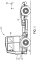
- Figure 1 illustrates a truck 100.
- the truck 100 is a cab-over truck, which means the nose of the truck is flat and the cabin stands above the engine of the truck.
- axis X is the longitudinal direction of the truck
- axis Y is the transverse direction of the truck
- axis Z is the vertical direction.
- the truck 100 comprises a frame 90 and a cabin 80 movable relatively to the frame 90.
- the cabin 80 is suspended relatively to the frame 90 of the truck 100.
- the cabin 80 is thus linked to the frame 90 by a set of springs and shock absorbers.
- the cabin 80 is also tiltable relatively to the frame 90 of the truck 100.
- the cabin 80 may be tilted forward when the truck 100 is not driven, for providing access to the engine, for example for maintenance operations to be performed on the engine.
- the cabin 80 is movable between an extreme upper position U and an extreme lower position L.
- the cabin 80 is movable around a reference position P comprised between the extreme upper position U and the extreme lower position L.
- the reference position P is defined as the rest position when no external constraint is applied to the cabin 80, i.e when the truck 100 is at standstill on a flat and level surface.
- the cabin 80 can move relatively to the frame 90 in response to the shocks generated by road irregularities, and/or by lateral cornering forces, and/or by longitudinal braking and acceleration forces. In normal driving conditions, the cabin 80 can have pitch, roll, and heave movements relatively to the frame 90, depending on the actual forces on the cabin.
- the truck 100 comprises a sealing assembly 50 that will be described in detail below.
- the sealing assembly 50 is disposed on a front corner of the truck 100.
- the proposed sealing assembly 50 for a truck 100 comprising a cabin 80 movable relatively to a truck frame 90 is configured for sealing a gap between the cabin 80 and a bodywork element 85 fixed relatively to the truck frame 90.
- the sealing assembly 50 comprises :
- the sealing assembly 50 is an airflow sealing assembly.
- the arrangement of the support member 4, the bracket 8 and the elastic member 9 provides a sealed junction between the support member 4 and the bodywork element 85 even when the position of the cabin 80 changes relatively to the frame 90.
- the gap between the cabin 80 and the bodywork element 85 fixed relatively to the truck frame 90 remains thus closed.
- the frame-fixed bodywork element 85 is a headlight panel of the truck 100.
- the frame-fixed bodywork element 85 can be a front grille of the truck 100.
- the support member 4 is rigid.
- the bracket 8 is rigid.
- the support member 4 is made of plastic material.
- the support member 4 is for example formed by plastic injection.
- the bracket 8 is made of plastic material.
- the bracket 8 can be formed by plastic injection.
- the first flange 5, the sealing member 7 and the second flange 6 are integral together.
- the bracket 8 can also be formed by an assembly of separated parts forming altogether the first flange 5, the sealing member 7 and the second flange 6.
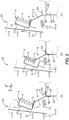
- Figure 2 is side view illustrating the interaction of the sealing assembly 50 with the bodywork element 85.
- a sealed junction between the support member 4 and the bodywork element 85 is formed when the bracket 8 is in contact with the bodywork element 85.
- the sealing member 7 provides a wall that deflects the air flow. The air flow is prevented from flowing in the gap between the cabin and the frame of the truck.
- the arrow F1 indicates the external air flow resulting from the truck motion and/or headwind.
- the sealing member 7 is an airflow deviating surface that seals the gap between the cabin 80 and the bodywork element 85 fixed relatively to the truck frame 90.
- the sealing member 7 of the bracket 8 is continuous. In other words, there is no hole in the sealing member 7.
- the sealing member 7 prevents the air flow from passing between the support member 4 and the bodywork element 85.
- the arrow F2 schematically indicates that the external air flow is blocked by the sealing member 7, and that the external air flow F1 can't progress in the gap between the cabin and the frame of the truck.
- the second flange 6 of the bracket 8 comprises:
- the two contact sections 6A, 6B each contacting a different portion of the bodywork element 85, provide an efficient sealing tolerant to relative movements between the bracket 8 and the bodywork element 85.
- the top surface 86 extends in a horizontal plan when the sealing assembly 50 is in its nominal installation position in the truck 100.
- the side surface 87 extends vertically when the sealing assembly 50 is in its nominal installation position in the truck 100.
- the second flange 6 has a L-shaped cross-section.
- the first section 6A and the second section 6B form the two wings of the L shape.
- the second abutment member 2 pulls the first flange 5 upwards, therefore the whole bracket 8 moves upwards.
- the first section 6A of the second flange 6 is lifted from the top surface 86 of frame-fixed bodywork element 85 and there's no contact any more between these two elements, as illustrated on part C of figure 2 .
- the second section 6B of the second flange 6 slides against a vertical section 87 of the frame-fixed bodywork element 85, and still seals the junction between the bracket 8 and the bodywork element 85.
- the contact area between the second section 6B and the vertical section 87 is progressively reduced but contact is still ensured as long as the cabin movement amplitude relatively to the reference position P is smaller than the height of the second section of the second flange 7.
- the different elements are disposed sequentially along a vertical axis Z in the following order: the frame-fixed bodywork element 85, the second flange 6 of the bracket 8, the sealing member 7 of the bracket 8, the second abutment member 2 of the support member 4, the first flange 5 of the bracket 8, the elastic member 9, and the first abutment member 1 of the support member 4.
- the first flange 5 extends on both sides of the axis of the sealing member 7.
- the sealing member 7 joins the first flange 5 in a T-like junction.
- At least a portion of the elastic member 9 is contained in the opened cavity defined by the C shape of the support member 4.
- the first abutment member 1 of the support member 4 and the second abutment member 2 of the support member 4 extend in parallel planes.
- the support member 4 comprises a linking portion 3 linking the first abutment member 1 and the second abutment member 2.
- a cross section of the support member 4 has a U shape.
- the support member 4 can thus be compact.
- the support member 4 is formed by plastic injection, the first abutment member 1, the second abutment member 2 and the linking portion 3 are integral together.
- the first flange 5 is slanted relatively to the second flange 6.
- the first flange 5 is slanted downwards, which means that the vertical position along the vertical axis Z decreases when the longitudinal position is moved in direction of the back of the truck 100. This orientation is well suited to cope with both translational movements and rotational movements of the cabin 80 with respect to the frame 90 of the truck 100.
- the first flange 5 makes an angle A1 comprised between 10° and 25° relatively to the first section 6A of the second flange 6.
- a cross section of the first flange 5 makes an angle comprised between 10° and 25° with respect to the part of the second flange 6 contacting the top of the bodywork element 85.
- first section 6A of the second flange 6 and the first flange 5 may extend in parallel planes.
- the sealing member 7 is slanted relatively to the first section 6A of the second flange 6 and is slanted relatively to the second section 6B of the second flange 6. This orientation is well suited to cope with both translation movements and rotation movements of the cabin 80 with respect to the frame 90 of the truck 100.
- a cross section of the sealing member 7 makes an angle A2 comprised, for example, between 65° and 80° with respect to a cross section of the first section 6A of the second flange 6.
- the first flange 5 is located closer to the front of the truck than the second flange 6 when the bracket 8 is in normal operation conditions.
- the second flange 6 and a contact area of the frame-fixed bodywork element 85 have complementary shapes. As illustrated on figures 2 to 4 , an external corner of the frame-fixed bodywork element 85 fits in an internal corner of the second flange 6.
- the contact area between the second flange 6 and the frame-fixed bodywork element 85 comprises at least a portion of the top surface 86 of the frame-fixed bodywork element 85 and at least a portion of the side surface 87 of the frame-fixed bodywork 85.
- Figure 3 and figure 4 represent an example of implementation in which the elastic member 9 comprises bellows type springs. More precisely, the elastic member 9 is in this case a bellows type spring. This kind of spring can be installed in a stable way.
- the elastic member 9 comprises a first contact surface 11 contacting the first abutment member 1 and a second contact surface 12 contacting the first flange 5 of the bracket 8.
- the first contact surface 11 of the elastic member 9 may be fixed to the first abutment member 1 of the support member 4.
- the first contact surface 11 of the elastic member 9 may be glued to the first abutment member 1, or may be fixed by screws.
- the elastic member 9 may comprise any other compressible element.
- the elastic member 9 may be any other compressible element.
- the compressible element can be continuous or divided in individual segments, based on the desired compressible function.
- the bellows type elastic member 9 comprises two wavy sections 13, 14 extending side by side.
- the two wavy sections 13, 14 are integral with a top linking part and a bottom linking part.
- the elastic member 9 defines a closed volume 15 with the wavy sections 13, 14 forming lateral boundaries of the closed volume 15.
- the elastic member 9 is here made of rubber material.
- the support member 4, the elastic member 9 and the first flange 5 of the bracket 8 define a closed volume 16 when the first flange 5 is in contact with the second abutment member 2.
- the elastic member 9 comprises a set of metal springs.
- the metal springs of the set of metal springs are for example helical springs.
- the metal springs of the set of metal springs extend in parallel directions and are spaced apart from one another.
- the support member 4 is configured to be attached to a bodywork element 75 of the cabin 80.
- the sealing assembly 50 can be fitted as an original equipment of a brand-new truck.
- the sealing assembly 50 can also be installed as an aftermarket equipment, since it can be attached to an existing piece of bodywork.
- the support member 4 is configured to be attached to a front lid 75 of the truck 100.
- the front lid 75 of the cabin 80 defines the front surface of the truck 100, located above the front bumper.
- the support member 4 is integral with a front lid 75 of the cabin 80.
- the installation of the sealing assembly 50 is made easier and quicker, since a key component is integral with the front lid 75 and doesn't require any installation or fitting.
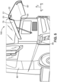
- the truck 100 is represented with the front lid 75 is an opened position. Therefore, the sealing assembly 50 is not in contact with the bodywork element 85.
- the sealing assembly 50 comprises a first portion 21 configured for extending transversally relatively to the truck frame 90 and a second portion 22 configured for extending longitudinally relatively to the truck frame 90.
- the first portion 21 and second portion 22 are linked by a third portion 23.
- the third portion 23 may be curved, as represented on figure 5 .
- the top of the headlight panel 85 is curved.
- a general shape of a horizontal cross-section is a quarter of a circle.
- the described sealing assembly 50 can be fitted as original equipment on a brand-new truck. As original equipment, it can be fitted as a standard equipment or as an option.
- the sealing assembly can also be proposed as an aftermarket kit for retrofit of trucks not originally equipped.
- the aftermarket kit 60 comprises:
- the aftermarket kit 60 can be sold by the manufacturer of the truck, or by independent suppliers.
- the aftermarket kit can be fitted to the truck 100 by the aftermarket network of the truck brand, or by an independent service provider.
- the truck 100 comprises a second sealing assembly 50' disposed on a second front corner of the truck 100.
- the first sealing assembly 50 and the second sealing assembly 50' are symmetrical with respect to a median plan.
- the first sealing assembly 50 and the second sealing assembly 50' are mirror images.
Landscapes
- Engineering & Computer Science (AREA)
- Mechanical Engineering (AREA)
- General Engineering & Computer Science (AREA)
- Physics & Mathematics (AREA)
- Acoustics & Sound (AREA)
- Geometry (AREA)
- Chemical & Material Sciences (AREA)
- Combustion & Propulsion (AREA)
- Transportation (AREA)
- Body Structure For Vehicles (AREA)
Priority Applications (2)
| Application Number | Priority Date | Filing Date | Title |
|---|---|---|---|
| EP23153975.0A EP4406784B1 (de) | 2023-01-30 | 2023-01-30 | Dichtungsanordnung für einen lastwagen mit einer beweglichen kabine |
| US18/413,245 US20240253437A1 (en) | 2023-01-30 | 2024-01-16 | Sealing assembly for a truck comprising a movable cabin |
Applications Claiming Priority (1)
| Application Number | Priority Date | Filing Date | Title |
|---|---|---|---|
| EP23153975.0A EP4406784B1 (de) | 2023-01-30 | 2023-01-30 | Dichtungsanordnung für einen lastwagen mit einer beweglichen kabine |
Publications (3)
| Publication Number | Publication Date |
|---|---|
| EP4406784A1 true EP4406784A1 (de) | 2024-07-31 |
| EP4406784B1 EP4406784B1 (de) | 2025-01-29 |
| EP4406784C0 EP4406784C0 (de) | 2025-01-29 |
Family
ID=85150796
Family Applications (1)
| Application Number | Title | Priority Date | Filing Date |
|---|---|---|---|
| EP23153975.0A Active EP4406784B1 (de) | 2023-01-30 | 2023-01-30 | Dichtungsanordnung für einen lastwagen mit einer beweglichen kabine |
Country Status (2)
| Country | Link |
|---|---|
| US (1) | US20240253437A1 (de) |
| EP (1) | EP4406784B1 (de) |
Citations (3)
| Publication number | Priority date | Publication date | Assignee | Title |
|---|---|---|---|---|
| US4082343A (en) * | 1974-01-23 | 1978-04-04 | Hurt Ii William C | Resiliently mounted cab-sidewall retainer |
| JPS5382021U (de) * | 1976-12-07 | 1978-07-07 | ||
| DE4341693C2 (de) * | 1992-12-30 | 2002-11-21 | Scania Cv Ab | Dämmung der Schallübertragung durch einen Zwischenraum zwischen Fahrzeugfahrgestell und Fahrerhaus |
-
2023
- 2023-01-30 EP EP23153975.0A patent/EP4406784B1/de active Active
-
2024
- 2024-01-16 US US18/413,245 patent/US20240253437A1/en active Pending
Patent Citations (3)
| Publication number | Priority date | Publication date | Assignee | Title |
|---|---|---|---|---|
| US4082343A (en) * | 1974-01-23 | 1978-04-04 | Hurt Ii William C | Resiliently mounted cab-sidewall retainer |
| JPS5382021U (de) * | 1976-12-07 | 1978-07-07 | ||
| DE4341693C2 (de) * | 1992-12-30 | 2002-11-21 | Scania Cv Ab | Dämmung der Schallübertragung durch einen Zwischenraum zwischen Fahrzeugfahrgestell und Fahrerhaus |
Also Published As
| Publication number | Publication date |
|---|---|
| EP4406784B1 (de) | 2025-01-29 |
| EP4406784C0 (de) | 2025-01-29 |
| US20240253437A1 (en) | 2024-08-01 |
Similar Documents
| Publication | Publication Date | Title |
|---|---|---|
| CN1640745A (zh) | 车架构件的冲击能吸收结构 | |
| US10981424B2 (en) | Suspension control arm with integrated resilient element | |
| AU2016204718B2 (en) | Devices and methods for reducing vehicle drag | |
| US10450012B2 (en) | Rear spoiler for muffler | |
| CN218505982U (zh) | 车身后部结构及车辆 | |
| US12037051B2 (en) | Flexible inner fender undercover | |
| EP4406784B1 (de) | Dichtungsanordnung für einen lastwagen mit einer beweglichen kabine | |
| CN110294030A (zh) | 车身下表面结构 | |
| CN103158770A (zh) | 车辆副架的结构 | |
| EP1241077B1 (de) | Lastkraftwagen mit niedrigem, ebenem Fahrerhausboden | |
| US20210053482A1 (en) | Multi-accessory bracket for bumper mounted accessories | |
| CN116374051A (zh) | 悬架总成与车身的自动合装系统、安装座及车辆 | |
| US20240190520A1 (en) | Vehicle with a gap between the chassis and the cab closed by a sealing device | |
| CN115973293B (zh) | 驾驶室以及车辆 | |
| CN1095773C (zh) | 车颈部分的结构 | |
| CN114684280A (zh) | 一种商用车全浮式驾驶室后悬装置 | |
| CN2794902Y (zh) | 汽车转向桥全空气前悬架结构 | |
| CN223934817U (zh) | 一种长头电动重卡全浮驾驶室悬置系统 | |
| US20250249718A1 (en) | Attachment structure for upper arm of double wishbone shock absorber | |
| CN218400108U (zh) | 一种汽车后悬挂总成 | |
| CN218141791U (zh) | 一种加强型汽车前围上部总成 | |
| CN103935403A (zh) | 树脂前端部的结构 | |
| CN1109620C (zh) | 车辆驾驶室安装用橡胶件 | |
| CN118124681A (zh) | 一种货车前围板总成 | |
| JP3539111B2 (ja) | 車両のエンジンマウント用フレーム |
Legal Events
| Date | Code | Title | Description |
|---|---|---|---|
| PUAI | Public reference made under article 153(3) epc to a published international application that has entered the european phase |
Free format text: ORIGINAL CODE: 0009012 |
|
| STAA | Information on the status of an ep patent application or granted ep patent |
Free format text: STATUS: THE APPLICATION HAS BEEN PUBLISHED |
|
| STAA | Information on the status of an ep patent application or granted ep patent |
Free format text: STATUS: REQUEST FOR EXAMINATION WAS MADE |
|
| AK | Designated contracting states |
Kind code of ref document: A1 Designated state(s): AL AT BE BG CH CY CZ DE DK EE ES FI FR GB GR HR HU IE IS IT LI LT LU LV MC ME MK MT NL NO PL PT RO RS SE SI SK SM TR |
|
| 17P | Request for examination filed |
Effective date: 20240723 |
|
| RBV | Designated contracting states (corrected) |
Designated state(s): AL AT BE BG CH CY CZ DE DK EE ES FI FR GB GR HR HU IE IS IT LI LT LU LV MC ME MK MT NL NO PL PT RO RS SE SI SK SM TR |
|
| GRAP | Despatch of communication of intention to grant a patent |
Free format text: ORIGINAL CODE: EPIDOSNIGR1 |
|
| STAA | Information on the status of an ep patent application or granted ep patent |
Free format text: STATUS: GRANT OF PATENT IS INTENDED |
|
| RIC1 | Information provided on ipc code assigned before grant |
Ipc: B60R 13/08 20060101AFI20240828BHEP |
|
| INTG | Intention to grant announced |
Effective date: 20240905 |
|
| GRAS | Grant fee paid |
Free format text: ORIGINAL CODE: EPIDOSNIGR3 |
|
| GRAA | (expected) grant |
Free format text: ORIGINAL CODE: 0009210 |
|
| STAA | Information on the status of an ep patent application or granted ep patent |
Free format text: STATUS: THE PATENT HAS BEEN GRANTED |
|
| AK | Designated contracting states |
Kind code of ref document: B1 Designated state(s): AL AT BE BG CH CY CZ DE DK EE ES FI FR GB GR HR HU IE IS IT LI LT LU LV MC ME MK MT NL NO PL PT RO RS SE SI SK SM TR |
|
| REG | Reference to a national code |
Ref country code: GB Ref legal event code: FG4D |
|
| REG | Reference to a national code |
Ref country code: CH Ref legal event code: EP |
|
| REG | Reference to a national code |
Ref country code: DE Ref legal event code: R096 Ref document number: 602023001801 Country of ref document: DE |
|
| REG | Reference to a national code |
Ref country code: IE Ref legal event code: FG4D |
|
| U01 | Request for unitary effect filed |
Effective date: 20250217 |
|
| U07 | Unitary effect registered |
Designated state(s): AT BE BG DE DK EE FI FR IT LT LU LV MT NL PT RO SE SI Effective date: 20250221 |
|
| U20 | Renewal fee for the european patent with unitary effect paid |
Year of fee payment: 3 Effective date: 20250218 |
|
| PG25 | Lapsed in a contracting state [announced via postgrant information from national office to epo] |
Ref country code: RS Free format text: LAPSE BECAUSE OF FAILURE TO SUBMIT A TRANSLATION OF THE DESCRIPTION OR TO PAY THE FEE WITHIN THE PRESCRIBED TIME-LIMIT Effective date: 20250429 |
|
| PG25 | Lapsed in a contracting state [announced via postgrant information from national office to epo] |
Ref country code: PL Free format text: LAPSE BECAUSE OF FAILURE TO SUBMIT A TRANSLATION OF THE DESCRIPTION OR TO PAY THE FEE WITHIN THE PRESCRIBED TIME-LIMIT Effective date: 20250129 |
|
| PG25 | Lapsed in a contracting state [announced via postgrant information from national office to epo] |
Ref country code: ES Free format text: LAPSE BECAUSE OF FAILURE TO SUBMIT A TRANSLATION OF THE DESCRIPTION OR TO PAY THE FEE WITHIN THE PRESCRIBED TIME-LIMIT Effective date: 20250129 |
|
| PG25 | Lapsed in a contracting state [announced via postgrant information from national office to epo] |
Ref country code: NO Free format text: LAPSE BECAUSE OF FAILURE TO SUBMIT A TRANSLATION OF THE DESCRIPTION OR TO PAY THE FEE WITHIN THE PRESCRIBED TIME-LIMIT Effective date: 20250429 Ref country code: IS Free format text: LAPSE BECAUSE OF FAILURE TO SUBMIT A TRANSLATION OF THE DESCRIPTION OR TO PAY THE FEE WITHIN THE PRESCRIBED TIME-LIMIT Effective date: 20250529 |
|
| PG25 | Lapsed in a contracting state [announced via postgrant information from national office to epo] |
Ref country code: HR Free format text: LAPSE BECAUSE OF FAILURE TO SUBMIT A TRANSLATION OF THE DESCRIPTION OR TO PAY THE FEE WITHIN THE PRESCRIBED TIME-LIMIT Effective date: 20250129 |
|
| PG25 | Lapsed in a contracting state [announced via postgrant information from national office to epo] |
Ref country code: GR Free format text: LAPSE BECAUSE OF FAILURE TO SUBMIT A TRANSLATION OF THE DESCRIPTION OR TO PAY THE FEE WITHIN THE PRESCRIBED TIME-LIMIT Effective date: 20250430 |
|
| PG25 | Lapsed in a contracting state [announced via postgrant information from national office to epo] |
Ref country code: SM Free format text: LAPSE BECAUSE OF FAILURE TO SUBMIT A TRANSLATION OF THE DESCRIPTION OR TO PAY THE FEE WITHIN THE PRESCRIBED TIME-LIMIT Effective date: 20250129 |
|
| PG25 | Lapsed in a contracting state [announced via postgrant information from national office to epo] |
Ref country code: MC Free format text: LAPSE BECAUSE OF FAILURE TO SUBMIT A TRANSLATION OF THE DESCRIPTION OR TO PAY THE FEE WITHIN THE PRESCRIBED TIME-LIMIT Effective date: 20250129 |
|
| PG25 | Lapsed in a contracting state [announced via postgrant information from national office to epo] |
Ref country code: CZ Free format text: LAPSE BECAUSE OF FAILURE TO SUBMIT A TRANSLATION OF THE DESCRIPTION OR TO PAY THE FEE WITHIN THE PRESCRIBED TIME-LIMIT Effective date: 20250129 |
|
| PG25 | Lapsed in a contracting state [announced via postgrant information from national office to epo] |
Ref country code: SK Free format text: LAPSE BECAUSE OF FAILURE TO SUBMIT A TRANSLATION OF THE DESCRIPTION OR TO PAY THE FEE WITHIN THE PRESCRIBED TIME-LIMIT Effective date: 20250129 |
|
| PLBE | No opposition filed within time limit |
Free format text: ORIGINAL CODE: 0009261 |
|
| STAA | Information on the status of an ep patent application or granted ep patent |
Free format text: STATUS: NO OPPOSITION FILED WITHIN TIME LIMIT |
|
| 26N | No opposition filed |
Effective date: 20251030 |
|
| PG25 | Lapsed in a contracting state [announced via postgrant information from national office to epo] |
Ref country code: IE Free format text: LAPSE BECAUSE OF NON-PAYMENT OF DUE FEES Effective date: 20250130 |
|
| U20 | Renewal fee for the european patent with unitary effect paid |
Year of fee payment: 4 Effective date: 20260126 |