EP4406730A1 - Maschine zur bearbeitung von linsen, vorzugsweise aus kunststoff - Google Patents
Maschine zur bearbeitung von linsen, vorzugsweise aus kunststoff Download PDFInfo
- Publication number
- EP4406730A1 EP4406730A1 EP24153447.8A EP24153447A EP4406730A1 EP 4406730 A1 EP4406730 A1 EP 4406730A1 EP 24153447 A EP24153447 A EP 24153447A EP 4406730 A1 EP4406730 A1 EP 4406730A1
- Authority
- EP
- European Patent Office
- Prior art keywords
- lens
- spindle
- machine
- axis
- housing seat
- Prior art date
- Legal status (The legal status is an assumption and is not a legal conclusion. Google has not performed a legal analysis and makes no representation as to the accuracy of the status listed.)
- Pending
Links
Images












Classifications
-
- B—PERFORMING OPERATIONS; TRANSPORTING
- B29—WORKING OF PLASTICS; WORKING OF SUBSTANCES IN A PLASTIC STATE IN GENERAL
- B29D—PRODUCING PARTICULAR ARTICLES FROM PLASTICS OR FROM SUBSTANCES IN A PLASTIC STATE
- B29D11/00—Producing optical elements, e.g. lenses or prisms
- B29D11/00009—Production of simple or compound lenses
- B29D11/00423—Plants for the production of simple or compound lenses
-
- B—PERFORMING OPERATIONS; TRANSPORTING
- B23—MACHINE TOOLS; METAL-WORKING NOT OTHERWISE PROVIDED FOR
- B23Q—DETAILS, COMPONENTS, OR ACCESSORIES FOR MACHINE TOOLS, e.g. ARRANGEMENTS FOR COPYING OR CONTROLLING; MACHINE TOOLS IN GENERAL CHARACTERISED BY THE CONSTRUCTION OF PARTICULAR DETAILS OR COMPONENTS; COMBINATIONS OR ASSOCIATIONS OF METAL-WORKING MACHINES, NOT DIRECTED TO A PARTICULAR RESULT
- B23Q7/00—Arrangements for handling work specially combined with or arranged in, or specially adapted for use in connection with, machine tools, e.g. for conveying, loading, positioning, discharging, sorting
- B23Q7/04—Arrangements for handling work specially combined with or arranged in, or specially adapted for use in connection with, machine tools, e.g. for conveying, loading, positioning, discharging, sorting by means of grippers
- B23Q7/046—Handling workpieces or tools
-
- B—PERFORMING OPERATIONS; TRANSPORTING
- B23—MACHINE TOOLS; METAL-WORKING NOT OTHERWISE PROVIDED FOR
- B23C—MILLING
- B23C3/00—Milling particular work; Special milling operations; Machines therefor
- B23C3/16—Working surfaces curved in two directions
-
- B—PERFORMING OPERATIONS; TRANSPORTING
- B23—MACHINE TOOLS; METAL-WORKING NOT OTHERWISE PROVIDED FOR
- B23K—SOLDERING OR UNSOLDERING; WELDING; CLADDING OR PLATING BY SOLDERING OR WELDING; CUTTING BY APPLYING HEAT LOCALLY, e.g. FLAME CUTTING; WORKING BY LASER BEAM
- B23K26/00—Working by laser beam, e.g. welding, cutting or boring
- B23K26/36—Removing material
- B23K26/362—Laser etching
-
- B—PERFORMING OPERATIONS; TRANSPORTING
- B24—GRINDING; POLISHING
- B24B—MACHINES, DEVICES, OR PROCESSES FOR GRINDING OR POLISHING; DRESSING OR CONDITIONING OF ABRADING SURFACES; FEEDING OF GRINDING, POLISHING, OR LAPPING AGENTS
- B24B13/00—Machines or devices designed for grinding or polishing optical surfaces on lenses or surfaces of similar shape on other work; Accessories therefor
- B24B13/0031—Machines having several working posts; Feeding and manipulating devices
- B24B13/0037—Machines having several working posts; Feeding and manipulating devices the lenses being worked by different tools, e.g. for rough-grinding, fine-grinding, polishing
-
- B—PERFORMING OPERATIONS; TRANSPORTING
- B29—WORKING OF PLASTICS; WORKING OF SUBSTANCES IN A PLASTIC STATE IN GENERAL
- B29D—PRODUCING PARTICULAR ARTICLES FROM PLASTICS OR FROM SUBSTANCES IN A PLASTIC STATE
- B29D11/00—Producing optical elements, e.g. lenses or prisms
- B29D11/00932—Combined cutting and grinding thereof
-
- B—PERFORMING OPERATIONS; TRANSPORTING
- B29—WORKING OF PLASTICS; WORKING OF SUBSTANCES IN A PLASTIC STATE IN GENERAL
- B29D—PRODUCING PARTICULAR ARTICLES FROM PLASTICS OR FROM SUBSTANCES IN A PLASTIC STATE
- B29D11/00—Producing optical elements, e.g. lenses or prisms
- B29D11/00951—Measuring, controlling or regulating
- B29D11/00961—Measuring, controlling or regulating using microprocessors or computers
-
- Y—GENERAL TAGGING OF NEW TECHNOLOGICAL DEVELOPMENTS; GENERAL TAGGING OF CROSS-SECTIONAL TECHNOLOGIES SPANNING OVER SEVERAL SECTIONS OF THE IPC; TECHNICAL SUBJECTS COVERED BY FORMER USPC CROSS-REFERENCE ART COLLECTIONS [XRACs] AND DIGESTS
- Y10—TECHNICAL SUBJECTS COVERED BY FORMER USPC
- Y10T—TECHNICAL SUBJECTS COVERED BY FORMER US CLASSIFICATION
- Y10T29/00—Metal working
- Y10T29/51—Plural diverse manufacturing apparatus including means for metal shaping or assembling
- Y10T29/5136—Separate tool stations for selective or successive operation on work
-
- Y—GENERAL TAGGING OF NEW TECHNOLOGICAL DEVELOPMENTS; GENERAL TAGGING OF CROSS-SECTIONAL TECHNOLOGIES SPANNING OVER SEVERAL SECTIONS OF THE IPC; TECHNICAL SUBJECTS COVERED BY FORMER USPC CROSS-REFERENCE ART COLLECTIONS [XRACs] AND DIGESTS
- Y10—TECHNICAL SUBJECTS COVERED BY FORMER USPC
- Y10T—TECHNICAL SUBJECTS COVERED BY FORMER US CLASSIFICATION
- Y10T483/00—Tool changing
- Y10T483/16—Tool changing with means to transfer work
Definitions
- the object of the present invention is a machine for processing lenses, preferably in plastic material.
- the machine according to the invention makes it possible to perform a greater number of machining operations than comparable machines by reducing processing times.
- the machine according to the invention is capable of performing all of the following operations on lenses:
- the machine according to the invention may be configured to perform all of the following further operations on lenses:
- the main lens processing steps are:
- the drilling, engraving and milling operations for lenses are added to the cutting operations. Therefore, if such operations are performed, the production cycle is slowed down.
- the cutting tool works in three axis.
- a first axis defines a linear movement
- the second and third axes are defined by two rotating lens support axes that operationally place the lens itself in movement around the second and third axis. Due to the limited number of axes the operational flexibility of such machines is, however, reduced.
- the cut is however influenced by the shape of the cutting tool. It follows that not all of the required work may be performed in a workmanlike manner.
- the tool that is used for the drilling, engraving and milling also works on three axes. Two rotating axes and one linear for moving the tool. Such machines are not however capable of performing drilling, engraving and milling using angles other than the direction that is normal to the surface of the lens.
- the operations for the loading of raw lenses and the unloading of processed lenses are also affected by those operations that are performed on the lenses themselves (cutting, drilling, engraving and milling).
- the main object of the present invention is therefore that of eliminating or at least mitigating the drawbacks of the aforementioned known technique in providing a machine for processing lenses, preferably in plastic material, that integrates the cutting operations and, when running, the operations for the drilling, engraving and milling of the lenses, thereby increasing the operational flexibility of current machines.
- a further object of the present invention is to provide a machine for processing lenses that is both capable of cutting in a direction that is normal to the surface of the lens (in also being able to use non-shaped tools) and at the same time capable of creating cutting angles that a shaped tool cannot create.
- a further object of the present invention is to provide a machine for processing lenses that makes it possible to perform the operations for the drilling, engraving and milling of lenses using angles other than the direction that is normal to the surface of the lens, thereby increasing the operational flexibility thereof, without, however affecting productivity.
- a further object of the present invention is to provide a machine for processing lenses that integrates operations for creating characters and drawings on the lenses, increasing the operational flexibility thereof, without, however affecting productivity.
- a further object of the present invention is to provide a machine for processing lenses that makes it possible perform the operations of loading and unloading lenses independently of the processing operations that are performed on the lenses.
- a further object of the present invention is to provide a machine for processing lenses that is mechanically reliable.
- a further object of the present invention is to provide a machine for processing lenses that is at the same time simple to construct.
- a further object of the present invention is to provide a machine for processing lenses that is simple to clean and maintain.
- the object of the present invention is a machine for processing lenses, preferably in plastic material.
- the machine 1 for processing lenses comprises a support structure 2, that in particular (as shown in the accompanying figures) may comprise a load-bearing frame 2' whereto, advantageously, panels 2" may be attached in order to delimit enclosed or partially enclosed housing seats and/or to define support floors.
- the machine 1 comprises an apparatus 10 for loading and storing raw lenses that in turn comprises a lens exit portion 11 and is installed on said support structure 2.
- the apparatus 10 for loading and storing raw lenses is suitable to move said raw lenses towards said lens exit portion 11.
- the apparatus 10 for loading and storing raw lenses is suitable to move said raw lenses towards said lens exit portion 11.
- the apparatus 10 for loading and storing raw lenses is controlled by a management and control unit 100, as shown in Figure 1 .
- the apparatus 10 for loading and storing raw lenses is made according to the description in Italian patent application No. 102022000012539 filed on behalf of the same applicant and incorporated herein in the entirety thereof by reference.
- the machine 1 comprises, furthermore:
- lens cutting refers to the operation that has the aim of obtaining a lens having a predefined perimeter contour by removing from a raw lens LG by means of cutting, the material that is external to said contour.
- the cut may follow a closed line or be defined by separate cutting lines.
- lens drilling refers to the operation that has the aim of making one or more holes in a lens that are intended, for example, to be used to fix the lens to the spectacle frame or for the insertion of decorative elements.
- lens milling refers to the operation that has the aim of obtaining upon a shaped lens - according to the shape of the spectacle frame - reliefs or seats for decorative elements, rhinestones or otherwise.
- lens engraving refers to the operation that has the aim of making one or more engravings on the surface of a lens that are intended, for example, to be used to fix the lens to the spectacle frame or for defining decorative elements.
- the lens cutting system 20 is installed onto said support structure 2 and comprises in turn:
- the lens drilling-milling-engraving system 30 is also installed on said support structure 2 and in turn comprises:
- the drilling, milling and engraving operations are performed separately from each other by means of specific tools; furthermore, the execution of all three operations is optional, it also being possible to envisage the execution of only one thereof.
- the use of articulated arms for the movement of the two spindle-holder heads 210 and 310 avoids the adoption of movement and linear sliding systems, which are subject to the problem of the depositing of falling machining swarf/shavings. This translates into increased ease of cleaning and maintenance.
- the processed lens unloading zone 40 is also obtained on said support structure 2.
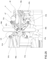
- the lens unloading zone 40 may be a simple finished lens passage zone without stationing, as shown in Figures 5 and 6 , or else it may be a zone for the storage of the finished lenses FL, wherein, for example, a collection vessel V may be arranged, as shown in Figure 25 .
- the lens exit portion 11 of said apparatus 10 for loading and storing raw lenses, the first lens housing seat 200 of said lens cutting system 20, the second lens housing seat 300 of said lens drilling-milling-engraving system 30 and said processed lens unloading zone 40 constitute four operating stations of said machine 1, indicated hereinafter respectively as the first, second, third and fourth stations.
- the aforementioned four stations are arranged in fixed positions. This is particularly advantageous for the lens loading operations which, insofar as they occur in a fixed position, are not influenced by any eventual lens format changes. A lens format change therefore occurs without loss of time due to the realignment of the position of the lenses. In other words the cycle setup is improved.
- the lens transfer apparatus 50 is suitable to pick up one lens at a time from said apparatus 10 for loading and storing at said lens exit portion 11 (first operating station) in order to bring it sequentially:
- the lens transfer apparatus 50 comprises a turret 51 having four lens suction-cup seats 51a,b,c,d for transporting lenses.
- Each of said transport seats 51a,b,c,d is suitable to receive one lens at a time.
- the lens transfer apparatus 50 comprises first motor means 52 suitable to rotate the turret around a turret axis X so as to cyclically bring each transport seat 51a,b,c,d in sequence to the aforementioned four operating stations.
- These four operating stations 11, 200, 300, 40 are arranged on a circumference centered on said turret axis X in angular positions spaced 90° apart from each other.
- said first motor means 52 are controlled by said management and control unit 100, as shown in Figure 1 .
- the operations for picking-up a new raw lens, lens cutting, lens drilling/milling/engraving and finished lens releasing are performed contemporaneously (fully operational) on four different lenses.
- the lens drilling, milling and engraving operations occur during running time with respect to the cutting operations.
- the downtimes for the transferring of a lens from one station to another are concentrated within a single time interval. This therefore avoids summing the various downtimes that are associated with a reduction in production time.
- the machine 1 for processing lenses, preferably in plastic material, according to the invention therefore integrates the lens cutting, drilling and milling operations, thereby increasing operating flexibility with respect to machines of the known art, and at the same time makes it possible to significantly reduce the downtime of transferring a lens from one station to another, so that productivity is less affected.
- the management and control unit 100 is programmed to control said lens transfer apparatus 50, said lens cutting system 20 and said lens drilling-milling-engraving 30 so that when fully operational the machine 1 cyclically repeats the following operating steps:
- machine 1 fully operational refers to the operating situation wherein machine 1 operates with the transport seats all engaged by one lens. In order to become “fully operational” the machine 1 passes through a transient operation state during which the operating cycle has not been completed (beginning with the picking-up of one raw lens; a single transport seat is engaged) with those transport seats that are only partially engaged. The passage from transient operation to fully operational takes place after four incomplete cycles, when all of the transport seats are engaged by lenses.
- the lens transfer apparatus 50 is mounted on guides 53 parallel to said turret axis and comprises second motor means 54 (which in particular may consist of a pneumatic cylinder) suitable to translate said lens transfer apparatus 50 parallel to said turret axis X so as to axially move each transport seat 51a,b,c,d towards or away from the corresponding operating station.
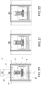
- said second motor means 54 are controlled by said management and control unit 100, as shown in Figures 1 and 20 .
- the turret 51 is moved away from the operating stations before rotating the turret itself by 90° so as to shift the transport seats 51 a,b,c,d from one operating station to another (see Figure 22 ).
- the turret 51 in instead moved towards the operating stations in such a way that those lenses that are transferred by the transport seats may operationally engage the operating stations (see Figure 21 ).
- the second and third operating station the cutting station and the drilling/milling/engraving station
- the axial pressure exerted by the respective transport seats of the turret allow the lenses to be held in a stable manner in the first lens housing seat and in the second lens housing seat.
- the lens transfer apparatus 50 is provided with a pneumatic suction-cup supply circuit 55 comprising four independent arms 55 a,b,c,d in order to independently feed each suction-cup of the transport seats.
- Each arm may be alternatively connected to a vacuum source and a pressure source, in such a way that the lens may be alternately vacuum held on the transport seat or else the lens may be detached from the transport seat generating a jet of pressurized air.
- the jet of air may also be used to keep the transport seat clean. In this way it is also possible to differentiate the intervention times from suction-cup to suction-cup.
- said turret 51 comprises four arms 57 a,b,c,d which extend in length radially from said turret axis X and each carries one of said lens transport seats 51a,b,c,d.
- each of the four arms are adjustable in inclination in relation to a plane that is orthogonal to the turret axis X and in length so as to able to adjust the orientation of the respective transport seat with respect to the first and second lens housing seat to be axially aligned and parallel thereto.
- Such adjustment reduces the risk of damage to the lens.
- the first lens housing seat 200 and the second lens housing seat 300 are both suitable to rotate the lens received thereby respectively around a first lens rotation axis X1 and a second lens rotation axis X2.
- first lens housing seat 200 and the second lens housing seat 300 both comprise:
- the lens transport seats 51a,b,c,d of the turret 51 are mounted rotationally free on the respective arm of the turret 51 around a rotation axis parallel to the turret axis X (for example by means of washers), in such a way that they may support the lenses in the first lens housing seat 200 and in the second lens housing seat 300 (in contact with the lens support) without hindering the rotation thereof.
- the first X1 and the second lens rotation axis X2 are parallel to each other, and in particular horizontally; the rotation axis X is parallel thereto.
- the first articulated arm 211 of the lens cutting system 20 consists of an articulated structure that:
- the first spindle-holder head 210 is rotationally associated with a free end of said structure articulated around a third axis Z3' of said first three rotation axes and in turn defines a first spindle rotation axis Y1 that lies on a plane orthogonal to said third axis Z3.
- the aforementioned three first rotation axes Z1', Z2', Z3' are vertical and the aforementioned first lens rotation axis X1 is horizontal.
- the plane on which there lies said first spindle axis Y1 is horizontal.
- each of said three first rotation axes Z1', Z2', Z3' is defined by a motorized shaft 221, 222, 223, controlled by said management and control unit 100 (as shown in Figure 7 ).
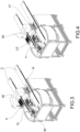
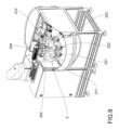
- the management and control unit 100 is programmed in order to adjust the orientation of the first spindle rotation axis Y1 with respect to the first lens housing seat 200 varying the angular position of the first spindle-holder head 210 around the third axis Z3' of said first three rotation axes, as may be seen in comparing figures 8 and 9 .
- regulating the orientation of the first spindle rotation axis Y1 with respect to the first lens housing seat 200 makes it possible to vary the angle of incidence of the tool upon the surface of the lens.
- the machine 1 capable of cutting normal to the surface of the lens in also being able to use unshaped tools as well as creating cutting angles that a shaped tool is unable to make.
- the management and control unit 100 is programmed to perform the cutting operations by generating a relative motion of contact between the lens and the tool supported by the first spindle-holder head 210, by rotating the lens around the first lens rotation axis X1 by means of the first lens housing seat 200 and adjusting the position of the first spindle rotation axis Y1 with respect to the first lens housing seat 200, as a function of a predefined lens cutting program.
- the lens cutting system 20 therefore operates on a total of four rotation axes: three axes Z1', Z2', Z3' given by the articulated structure and a forth axis corresponding to the first rotation axis X1.
- the rotations around each of said four axes are independently controlled by the management and control unit 100 and may be exploited in order to define a relative motion between lens and tool that, through interpolation, reproduces a predefined lens cutting line.
- the first spindle-holder head 210 is single-spindle and is suitable to support one cutting tool at a time.
- the machine 1 comprises a cutting tool storage 80 which is supported by said support structure 2 in a position reachable by said first spindle-holder head 210 by means of said first articulated arm 211.
- the second articulated arm 311 of the lens drilling-milling-engraving system 30 comprises an articulated structure 312 that has three second rotation axes Z1", Z2", Z3" that are parallel to each other.
- the second spindle-holder head 310 is rotationally associated with a free end of said articulated structure 312 around a third axis Z3" of said second rotation axes and defines at least one second spindle rotation axis Y2a,b,c which lies on a plane orthogonal to said third axis Z3".
- Said articulated structure 312 is connected to the support structure 2 of the machine 1 by means of a mechanism 313 suitable to translate said articulated structure 312 orthogonally to the plane in which said at least a second spindle axis Y2a,b,c lies.
- the mechanism 313 is motorized.
- said mechanism 313 consists of an articulated parallelogram connection system (or a pantograph).
- the four sides of the articulated parallelogram are indicated with 313 a,b,c,d in the figures, whilst the four axes of articulation (parallel to each other) are indicated with Y3 a,b,c,d.
- the articulated parallelogram connection system 313 is configured to translate said articulated structure 312 orthogonally to the plane in which said at least one second spindle axis Y2 lies by means of rotations around a first articulated parallelogram axis Y3a whereto the articulated parallelogram connection system 313 is connected to the support structure 2 of the machine 1.
- the opposite sides of the articulated parallelogram are equal one to the other.
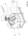
- each of said three second rotation axes Z1", Z2", Z3" and said first articulated parallelogram axis Y3a is defined by a motorized shaft 321, 322, 323, 324, controlled by said management and control unit 100 (as shown in Figure 12 ).
- the aforementioned three second rotation axes Z1", Z2", Z3" are vertical and said second lens rotation axis X2 is horizontal.
- the plane whereupon said at least a second spindle axis Y2a,b,c lies is horizontal, and the first articulated parallelogram axis Y3a is horizontal.
- the articulated parallelogram connection system 313 may be locked in position by means of the braking action exerted by the motor means of the motorized shaft.
- the articulated parallelogram connection system 313 may comprise an auxiliary weight balancing system 314 that is suitable to replace/supplant the motor braking action in the case of a stoppage of machine 1.
- such weight balancing system 314 is constituted by a pneumatic or hydraulic cylinder 315 that connects, by means of two hinges 316a and 316b, the articulated parallelogram connection system 313 to said support structure 2 of the machine 1 in an opposite position with respect to the first articulated parallelogram axis Y3a.
- the second spindle-holder head 310 is multi-spindle and comprises:
- Each of said spindles 341, 342, 343 defines a second spindle rotation axis Y2a,b,c thereof that lies on a plane orthogonally to said third axis Z3".
- the spindles are each provided with independent motorized means (preferably electric).
- the spindles have in common the same motors 351.
- the motor means 351 are connected to the single spindles by means of a transmission system 350 and by a distribution system 352, that in particular may comprise a conical wheel for each spindle.
- the second spindle-holder head 310 is multi-spindle (in particular tri-spindle) it may work directly with multiple tool versions thereby eliminating tool change-over downtimes. This leads to a further increase in productivity.
- management and control unit 100 is programmed to:
- the management and control unit 100 is programmed to perform the lens drilling-milling-engraving operations, by generating a relative motion of contact between the lens and one of the tools supported by the second spindle-holder head 310 by means of rotations, also only partial rotations, of the lens around the second lens rotation axis X2 by means of the second lens housing seat 300 and adjusting the position of the tool as well as the orientation of the second spindle rotation axis Y2a,b,c with respect to the second lens housing seat 300, as a function of a predefined lens drilling-milling-engraving program.
- the lens drilling-milling-engraving system 30 thus operates on a total of five rotation axes: three axes given by the articulated structure, a forth axis corresponding to the first articulated parallelogram axis Y3a and a fifth axis corresponding to the second lens rotation axis X2.
- the rotations around each of said five axes are independently controlled by the management and control unit 100 and may be exploited in order to define a relative motion between lens and tool that, through interpolation, reproduces a predefined lens drilling-milling-engraving path.
- the use of articulated arms with parallel axes makes it possible to reduce the amplitude of the excursions in the movements of the spindle-holder heads. This results in less demand for space and thus greater compactness of the machine itself. By virtue of the compactness of the dimensions the machine 1 may be arranged within smaller spaces and is therefore easier to install.
- the support structure 2 of the machine 1 delimits:
- Said first operating area 2a is confined to a closed chamber 3. In this way the shavings produced by the cutting, drilling, milling, engraving operations are confined to the closed chamber and not dispersed throughout the machine. This facilitates the cleaning and maintenance operations.
- said second operating area 2b is obtained above said closed chamber 3.
- said second operating area 2b and said closed chamber 3 are separated by a partition wall 4 which preferably acts as a support plane for the apparatus 10 for loading and storing raw lenses and the processed lens unloading zone 40.
- the lenses transfer apparatus 50 is arranged between said second operating area 2b and said closed chamber 3.
- a slit 5 is open in said partition wall 4 for the free passage of the turret 51.
- the slit 5 extends in length transversely to said turret axis X which passes on the middle line of said slit.
- the turret 51 is provided with four paddles 56 a,b,c,d, which:
- the presence of the paddles keeps the two operating areas 2a and 2b separate thereby preventing shavings from moving from the first operational area to the second.
- the closed chamber 3 is delimited therebelow by a back wall 7, that has at least one inclined portion 7a serving as a chute for shavings from the lens processing to a portion of the back wall whereinto one or more through holes 8 are cut whereto suction systems D may be connected for automatic shavings removal.
- the cutting tool storage 80 is arranged in said second operating area 2b near a hatch 6 which is obtained on said partition wall 5.
- said storage 80 is temporarily positionable in said first operating area 2a, passing through said hatch 6 by means of a movement mechanism 81 to allow said first spindle-holder head 310 to reach said storage 80 remaining inside said first operating area 2a.
- the movement mechanism 81 is provided with an actuator that is controlled by said management and control unit 100, as shown in Figure 1 .
- said machine 1 comprises at least one robotic arm 60 that is suitable to:
- the machine 1 may be provided with two conveyor belts C whereupon one or more raw lens storages A and one or more processed lens collection storages B may be arranged for the automated handling thereof.
- the machine 1 may comprise a system 70 for creating characters and/or drawings on the lenses by means of lasers or printing systems.
- said system 70 for creating characters and/or drawings is within a zone of said machine 1 not reachable by said turret 41.
- said robotic arm 60 is also suitable to:
- the machine 1 for processing lenses integrates the cutting operations and, when running, the operations for the drilling, engraving and milling of the lenses, thereby increasing the operational flexibility of current machines, significantly reducing the downtime of transferring a lens from one station to another.
- the machine 1 for processing lenses according to the invention makes it possible to perform the operations of loading and unloading lenses independently of the processing operations that are performed on the lenses.
- the machine 1 for processing lenses according to the invention is capable of cutting in a direction that is normal to the surface of the lens (also being able to use non-shaped tools) and at the same time capable of creating cutting angles that a shaped tool cannot achieve.
- the machine 1 for processing lenses according to the invention makes it possible to perform the operations for the drilling, engraving and milling of lenses using angles other than the direction that is normal to the surface of the lens, thereby increasing the operational flexibility thereof, without, however affecting productivity.
- the machine 1 for processing lenses according to the invention may also integrate operations for creating characters and drawings on the lenses, increasing the operational flexibility thereof, without, however affecting productivity.
- the machine 1 for processing lenses according to the invention is mechanically reliable.
- the machine 1 for processing lenses according to the invention is, at the same time, constructively simple to create.
- the machine 1 for processing lenses according to the invention is easy to clean and maintain.
Landscapes
- Engineering & Computer Science (AREA)
- Mechanical Engineering (AREA)
- Health & Medical Sciences (AREA)
- Manufacturing & Machinery (AREA)
- Ophthalmology & Optometry (AREA)
- Physics & Mathematics (AREA)
- Optics & Photonics (AREA)
- Microelectronics & Electronic Packaging (AREA)
- Plasma & Fusion (AREA)
- Grinding And Polishing Of Tertiary Curved Surfaces And Surfaces With Complex Shapes (AREA)
- Milling Processes (AREA)
Applications Claiming Priority (1)
| Application Number | Priority Date | Filing Date | Title |
|---|---|---|---|
| IT102023000001107A IT202300001107A1 (it) | 2023-01-25 | 2023-01-25 | Macchina per la lavorazione di lenti, preferibilmente in materiale plastico |
Publications (1)
| Publication Number | Publication Date |
|---|---|
| EP4406730A1 true EP4406730A1 (de) | 2024-07-31 |
Family
ID=85936982
Family Applications (1)
| Application Number | Title | Priority Date | Filing Date |
|---|---|---|---|
| EP24153447.8A Pending EP4406730A1 (de) | 2023-01-25 | 2024-01-23 | Maschine zur bearbeitung von linsen, vorzugsweise aus kunststoff |
Country Status (3)
| Country | Link |
|---|---|
| US (1) | US20240246185A1 (de) |
| EP (1) | EP4406730A1 (de) |
| IT (1) | IT202300001107A1 (de) |
Families Citing this family (2)
| Publication number | Priority date | Publication date | Assignee | Title |
|---|---|---|---|---|
| DE102019006504A1 (de) * | 2019-09-16 | 2021-03-18 | Satisloh Ag | Optikmaschine für das Behandeln und/oder Bearbeiten von optischen Werkstücken, wie Brillengläsern, sowie Abblockvorrichtung und Abblockverfahren hierfür |
| CN119407549B (zh) * | 2025-01-09 | 2025-04-11 | 江西秦锐智能科技有限公司 | 一种多工位数控机床的铣削加工台 |
Citations (4)
| Publication number | Priority date | Publication date | Assignee | Title |
|---|---|---|---|---|
| US20060260448A1 (en) * | 2005-05-06 | 2006-11-23 | Udo Fiedler | High-performance cutting and turning machine and method for machining particularly spectacle lenses |
| EP3747641A2 (de) * | 2019-06-07 | 2020-12-09 | Schneider GmbH & Co. KG | Verfahren und vorrichtung zur herstellung von optischen linsen |
| US20210170540A1 (en) * | 2018-09-04 | 2021-06-10 | Schneider Gmbh & Co. Kg | Processing system for processing spectacle lenses |
| IT202200012539A1 (it) | 2022-06-14 | 2023-12-14 | Costruzioni Mecc E Tecnologiche S R L | Apparato di caricamento ed accumulo di pezzi semilavorati piastriformi, in particolare lenti |
-
2023
- 2023-01-25 IT IT102023000001107A patent/IT202300001107A1/it unknown
-
2024
- 2024-01-23 EP EP24153447.8A patent/EP4406730A1/de active Pending
- 2024-01-24 US US18/421,800 patent/US20240246185A1/en active Pending
Patent Citations (4)
| Publication number | Priority date | Publication date | Assignee | Title |
|---|---|---|---|---|
| US20060260448A1 (en) * | 2005-05-06 | 2006-11-23 | Udo Fiedler | High-performance cutting and turning machine and method for machining particularly spectacle lenses |
| US20210170540A1 (en) * | 2018-09-04 | 2021-06-10 | Schneider Gmbh & Co. Kg | Processing system for processing spectacle lenses |
| EP3747641A2 (de) * | 2019-06-07 | 2020-12-09 | Schneider GmbH & Co. KG | Verfahren und vorrichtung zur herstellung von optischen linsen |
| IT202200012539A1 (it) | 2022-06-14 | 2023-12-14 | Costruzioni Mecc E Tecnologiche S R L | Apparato di caricamento ed accumulo di pezzi semilavorati piastriformi, in particolare lenti |
Also Published As
| Publication number | Publication date |
|---|---|
| US20240246185A1 (en) | 2024-07-25 |
| IT202300001107A1 (it) | 2024-07-25 |
Similar Documents
| Publication | Publication Date | Title |
|---|---|---|
| EP4406730A1 (de) | Maschine zur bearbeitung von linsen, vorzugsweise aus kunststoff | |
| US5704262A (en) | Multiple-spindle lathe | |
| KR100371763B1 (ko) | 머쉬이닝센터 | |
| US8628071B2 (en) | Device for finish-machining of optically effective surfaces of workpieces, in particular spectacle lenses | |
| KR100941334B1 (ko) | 터릿 툴 및 기계가공 툴 | |
| EP0519466B1 (de) | Zweispindeleinheit mit vertikaler Achse zum Drehen und Nuten von Kolben in eine CNC-Maschine | |
| CN1172448A (zh) | 带有水平主轴的机床 | |
| EP2163334B1 (de) | Maschine mit einer Trommel mit Werkstückspindeln, die in der Längsachse der Trommel bewegbar sind | |
| CN1203139A (zh) | 加工单元 | |
| JP2022020366A (ja) | 工作機械 | |
| JPS6219373A (ja) | 研削盤のためのといし車交換システム | |
| CN112192238A (zh) | 一种镜像运动复合切削的无人终端设备 | |
| EP3851244B1 (de) | Numerisch gesteuertes drehzentrum mit portalstruktur | |
| EP1904269A1 (de) | Feinziehschleifmaschine und -verfahren | |
| US5016334A (en) | Multiple spindle bar machine | |
| CN116803603A (zh) | 刀库装置 | |
| US20230039453A1 (en) | A numerically controlled turning center with double turning axis | |
| CN112059622A (zh) | 一种双主轴车铣中心复合设备 | |
| JP3911441B2 (ja) | ワーク受渡し装置 | |
| KR102530302B1 (ko) | Cnc선반용 소재 적재장치 | |
| KR20180109943A (ko) | 공작 기계 | |
| JPS61241051A (ja) | 円筒研削盤 | |
| KR0174922B1 (ko) | 자동 가공물 교환기 | |
| US4848039A (en) | Method and apparatus for grinding multiple workpieces | |
| US11163295B2 (en) | Continuous machining with robotic table tracking of fixture |
Legal Events
| Date | Code | Title | Description |
|---|---|---|---|
| PUAI | Public reference made under article 153(3) epc to a published international application that has entered the european phase |
Free format text: ORIGINAL CODE: 0009012 |
|
| STAA | Information on the status of an ep patent application or granted ep patent |
Free format text: STATUS: THE APPLICATION HAS BEEN PUBLISHED |
|
| AK | Designated contracting states |
Kind code of ref document: A1 Designated state(s): AL AT BE BG CH CY CZ DE DK EE ES FI FR GB GR HR HU IE IS IT LI LT LU LV MC ME MK MT NL NO PL PT RO RS SE SI SK SM TR |
|
| STAA | Information on the status of an ep patent application or granted ep patent |
Free format text: STATUS: REQUEST FOR EXAMINATION WAS MADE |
|
| 17P | Request for examination filed |
Effective date: 20241202 |
|
| RBV | Designated contracting states (corrected) |
Designated state(s): AL AT BE BG CH CY CZ DE DK EE ES FI FR GB GR HR HU IE IS IT LI LT LU LV MC ME MK MT NL NO PL PT RO RS SE SI SK SM TR |