EP4406493A1 - Ablenkungsdetektionsstruktur und steuerungsverfahren dafür, elektrisches klammergerät und medizinische vorrichtung - Google Patents
Ablenkungsdetektionsstruktur und steuerungsverfahren dafür, elektrisches klammergerät und medizinische vorrichtung Download PDFInfo
- Publication number
- EP4406493A1 EP4406493A1 EP22871620.5A EP22871620A EP4406493A1 EP 4406493 A1 EP4406493 A1 EP 4406493A1 EP 22871620 A EP22871620 A EP 22871620A EP 4406493 A1 EP4406493 A1 EP 4406493A1
- Authority
- EP
- European Patent Office
- Prior art keywords
- deflection
- action
- interface
- component
- motor
- Prior art date
- Legal status (The legal status is an assumption and is not a legal conclusion. Google has not performed a legal analysis and makes no representation as to the accuracy of the status listed.)
- Pending
Links
Images


Classifications
-
- A—HUMAN NECESSITIES
- A61—MEDICAL OR VETERINARY SCIENCE; HYGIENE
- A61B—DIAGNOSIS; SURGERY; IDENTIFICATION
- A61B90/00—Instruments, implements or accessories specially adapted for surgery or diagnosis and not covered by any of the groups A61B1/00 - A61B50/00, e.g. for luxation treatment or for protecting wound edges
- A61B90/06—Measuring instruments not otherwise provided for
-
- A—HUMAN NECESSITIES
- A61—MEDICAL OR VETERINARY SCIENCE; HYGIENE
- A61B—DIAGNOSIS; SURGERY; IDENTIFICATION
- A61B34/00—Computer-aided surgery; Manipulators or robots specially adapted for use in surgery
- A61B34/70—Manipulators specially adapted for use in surgery
- A61B34/74—Manipulators with manual electric input means
-
- A—HUMAN NECESSITIES
- A61—MEDICAL OR VETERINARY SCIENCE; HYGIENE
- A61B—DIAGNOSIS; SURGERY; IDENTIFICATION
- A61B17/00—Surgical instruments, devices or methods
- A61B17/068—Surgical staplers, e.g. containing multiple staples or clamps
- A61B17/072—Surgical staplers, e.g. containing multiple staples or clamps for applying a row of staples in a single action, e.g. the staples being applied simultaneously
- A61B17/07207—Surgical staplers, e.g. containing multiple staples or clamps for applying a row of staples in a single action, e.g. the staples being applied simultaneously the staples being applied sequentially
-
- A—HUMAN NECESSITIES
- A61—MEDICAL OR VETERINARY SCIENCE; HYGIENE
- A61B—DIAGNOSIS; SURGERY; IDENTIFICATION
- A61B17/00—Surgical instruments, devices or methods
- A61B17/32—Surgical cutting instruments
- A61B17/3209—Incision instruments
-
- G—PHYSICS
- G01—MEASURING; TESTING
- G01B—MEASURING LENGTH, THICKNESS OR SIMILAR LINEAR DIMENSIONS; MEASURING ANGLES; MEASURING AREAS; MEASURING IRREGULARITIES OF SURFACES OR CONTOURS
- G01B21/00—Measuring arrangements or details thereof, where the measuring technique is not covered by the other groups of this subclass, unspecified or not relevant
- G01B21/22—Measuring arrangements or details thereof, where the measuring technique is not covered by the other groups of this subclass, unspecified or not relevant for measuring angles or tapers; for testing the alignment of axes
-
- A—HUMAN NECESSITIES
- A61—MEDICAL OR VETERINARY SCIENCE; HYGIENE
- A61B—DIAGNOSIS; SURGERY; IDENTIFICATION
- A61B17/00—Surgical instruments, devices or methods
- A61B2017/00017—Electrical control of surgical instruments
-
- A—HUMAN NECESSITIES
- A61—MEDICAL OR VETERINARY SCIENCE; HYGIENE
- A61B—DIAGNOSIS; SURGERY; IDENTIFICATION
- A61B17/00—Surgical instruments, devices or methods
- A61B17/00234—Surgical instruments, devices or methods for minimally invasive surgery
- A61B2017/00292—Surgical instruments, devices or methods for minimally invasive surgery mounted on or guided by flexible, e.g. catheter-like, means
- A61B2017/003—Steerable
-
- A—HUMAN NECESSITIES
- A61—MEDICAL OR VETERINARY SCIENCE; HYGIENE
- A61B—DIAGNOSIS; SURGERY; IDENTIFICATION
- A61B17/00—Surgical instruments, devices or methods
- A61B2017/00367—Details of actuation of instruments, e.g. relations between pushing buttons, or the like, and activation of the tool, working tip, or the like
- A61B2017/00398—Details of actuation of instruments, e.g. relations between pushing buttons, or the like, and activation of the tool, working tip, or the like using powered actuators, e.g. stepper motors, solenoids
-
- A—HUMAN NECESSITIES
- A61—MEDICAL OR VETERINARY SCIENCE; HYGIENE
- A61B—DIAGNOSIS; SURGERY; IDENTIFICATION
- A61B17/00—Surgical instruments, devices or methods
- A61B17/068—Surgical staplers, e.g. containing multiple staples or clamps
- A61B17/072—Surgical staplers, e.g. containing multiple staples or clamps for applying a row of staples in a single action, e.g. the staples being applied simultaneously
- A61B2017/07214—Stapler heads
- A61B2017/07257—Stapler heads characterised by its anvil
-
- A—HUMAN NECESSITIES
- A61—MEDICAL OR VETERINARY SCIENCE; HYGIENE
- A61B—DIAGNOSIS; SURGERY; IDENTIFICATION
- A61B17/00—Surgical instruments, devices or methods
- A61B17/068—Surgical staplers, e.g. containing multiple staples or clamps
- A61B17/072—Surgical staplers, e.g. containing multiple staples or clamps for applying a row of staples in a single action, e.g. the staples being applied simultaneously
- A61B2017/07214—Stapler heads
- A61B2017/07278—Stapler heads characterised by its sled or its staple holder
-
- A—HUMAN NECESSITIES
- A61—MEDICAL OR VETERINARY SCIENCE; HYGIENE
- A61B—DIAGNOSIS; SURGERY; IDENTIFICATION
- A61B17/00—Surgical instruments, devices or methods
- A61B17/068—Surgical staplers, e.g. containing multiple staples or clamps
- A61B17/072—Surgical staplers, e.g. containing multiple staples or clamps for applying a row of staples in a single action, e.g. the staples being applied simultaneously
- A61B2017/07214—Stapler heads
- A61B2017/07285—Stapler heads characterised by its cutter
-
- A—HUMAN NECESSITIES
- A61—MEDICAL OR VETERINARY SCIENCE; HYGIENE
- A61B—DIAGNOSIS; SURGERY; IDENTIFICATION
- A61B90/00—Instruments, implements or accessories specially adapted for surgery or diagnosis and not covered by any of the groups A61B1/00 - A61B50/00, e.g. for luxation treatment or for protecting wound edges
- A61B90/06—Measuring instruments not otherwise provided for
- A61B2090/064—Measuring instruments not otherwise provided for for measuring force, pressure or mechanical tension
- A61B2090/065—Measuring instruments not otherwise provided for for measuring force, pressure or mechanical tension for measuring contact or contact pressure
-
- A—HUMAN NECESSITIES
- A61—MEDICAL OR VETERINARY SCIENCE; HYGIENE
- A61B—DIAGNOSIS; SURGERY; IDENTIFICATION
- A61B90/00—Instruments, implements or accessories specially adapted for surgery or diagnosis and not covered by any of the groups A61B1/00 - A61B50/00, e.g. for luxation treatment or for protecting wound edges
- A61B90/06—Measuring instruments not otherwise provided for
- A61B2090/067—Measuring instruments not otherwise provided for for measuring angles
Definitions
- the present disclosure relates to a field of medical device technology, and in particular to a deflection detector, a method of controlling a deflection detector, an electric stapler, and a medical device.
- a jaw component at a front end of an existing electric stapler is required to be able to deflect after entering the human body, so that a staple cartridge may contact lesions at different positions and angles to complete a surgery.
- a staple cartridge may contact lesions at different positions and angles to complete a surgery.
- due to a limited operating space and limited field of view in the human body there may be collisions with internal tissues and organs or discontinuous deflection angles during the deflection process, leading to the inability to reach the lesion location.
- the surgery cannot be effectively completed, while in severe cases, it may cause organ damage and expand the surgical scope.
- there is a maximum angle limitation on the deflection of the jaw component at the front end of the existing electric stapler there is a maximum angle limitation on the deflection of the jaw component at the front end of the existing electric stapler.
- An aspect of the present disclosure provides a deflection detector, applied to a detection on a deflection action of an operating end of a medical device, including a driving portion, an interface portion and a detecting portion.
- the driving portion is used to perform a rotation action to provide a driving force for achieving the deflection action of the operating end;
- the interface portion is in transmission connection with the driving portion and used to convert the rotation action of the driving portion into a linear movement action along an axial direction;
- the detecting portion is provided on the interface portion and used to detect a movement position of the linear movement action of the interface portion along the axial direction relative to a supporting portion, so as to complete the detection on the deflection action.
- the deflection detector further includes the supporting portion used to support the deflection detector, wherein the driving portion is provided on the supporting portion.
- the supporting portion includes a supporting frame, a rotating head and a rotating housing.
- the supporting frame is a frame structure with a hollow space and serves as a supporting main body of the supporting portion;
- the rotating head is a cylindrical structure, is provided at an end of the supporting frame facing the operating end, and serves as a contact end between the supporting portion and the interface portion; and the rotating housing covers the rotating head and the interface portion and is used to rotate relative to the supporting frame, wherein an opening of the rotating housing is matched with an outer-ring surface of the cylindrical structure of the rotating head.
- the driving portion includes a switching component and a motor component.
- the switching component is opposite to the rotating housing, is provided on the supporting frame, and serves as a driving switch for the driving portion when the switching component is in contact with the rotating housing; and the motor component is electrically connected to the switching component, provided in an accommodating space of the supporting frame, and used to provide the driving force in response to a driving switch action of the switching component, so as to provide the rotation action to the interface portion.
- the switching component includes a switching element and a circuit board.
- the switching element is arranged opposite to the opening of the rotating housing and serves as a contact element of the driving switch; and the circuit board is provided on a side of the switching element, embedded on the supporting frame, electrically connected to the motor component, and used to generate an electrical signal for controlling a motor rotation direction of the motor component.
- the rotating housing includes a semi-ring convex portion provided on the rotating housing along an outer edge of the opening of the rotating housing and opposite to the switching element, wherein two end portions of the semi-ring convex portion have sloping surfaces, wherein when the rotating housing rotates relative to the supporting frame and the sloping surface of the end portion of the semi-ring convex portion is in contact with the switching element, the switching element triggers an electrical contact on the circuit board to generate the electrical signal for controlling the motor rotation direction of the motor component.
- the motor component includes a motor unit and a gear unit.
- the motor unit has an output motor and is used to control the output motor to rotate according to the electrical signal for the motor rotation direction, so as to provide the driving force; and the gear unit is in transmission connection with the motor unit and used to convert the driving force into the rotation action.
- the interface portion includes an interface seat and a transmitter.
- the interface seat is in transmission connection with a gear unit of the motor component and used to convert the rotation action of the driving portion into the linear movement action along the axial direction; and the transmitter has an end connected to the interface seat and the other end connected to the operating end, wherein the transmitter is used to convert the linear movement action of the interface seat into the deflection action of the operating end.
- the detecting portion includes a thimble component provided in a fixed hole of the interface seat and used to detect the movement position of the linear movement action of the interface portion along the axial direction relative to the supporting portion.
- the thimble component includes a plurality of thimbles, a thimble sleeve, and a fixed sleeve.
- the plurality of thimbles are in contact with electrical contacts of the supporting portion, wherein different detection signals are formed in response to electrical contacts at different positions being detected, and the movement position is fed back using the detection signal;
- the thimble sleeve is sheathed the plurality of thimbles, and used to provide attachment positions for the plurality of thimbles;
- the fixed sleeve is sheathed the thimble sleeve, provided in the fixed hole of the interface seat, matched with the fixed hole, and used to fix the thimble sleeve sheathed the plurality of thimbles in the fixed hole.
- the supporting portion further includes a limiting plate provided on an edge of an end surface of the rotating head facing the interface portion and corresponding to the fixed hole of the interface seat, wherein a rear end electrical contact group, a zero position electrical contact group, and a front end electrical contact group are provided on a surface of the limiting plate facing the interface seat, and movement position detections on a rear end position, a zero position, and a front end position of the interface portion relative to the supporting portion are achieved when the rear end electrical contact group, the zero position electrical contact group, and the front end electrical contact group are respectively in contact with the plurality of thimbles of the thimble component.
- Another aspect of the present disclosure provides a method of controlling the above-described deflection detector, including: providing, by the driving portion of the deflection detector, the driving force for achieving the deflection action of the operating end, in response to a detection instruction; converting, using the interface portion of the deflection detector, the rotation action of the driving portion into the linear movement action along the axial direction; and controlling the detecting portion of the deflection detector to detect the movement position of the linear movement action of the interface portion along the axial direction relative to the supporting portion, so as to complete the detection on the deflection action.
- an electric stapler including the above-described deflection detector and a jaw component
- the above-described deflection detector is used to detect the movement position of the linear movement action of the interface portion along the axial direction relative to the supporting portion
- the jaw component is in transmission connection with the interface portion of the deflection detector and serves as the operating end to perform the deflection action according to the detection on the movement position.
- Another aspect of the present disclosure provides a medical device including the deflection detector described above.
- ordinal numbers such as “first”, “second”, “third”, etc. in the specification and claims for describing the corresponding elements does not imply that the element has any ordinal numbers, nor does it represent the order of one element and another element or the order of the manufacturing method.
- the use of these ordinal numbers is only to enable an element with a certain name to be clearly distinguished from another element with the same name.
- modules in the devices in embodiments may be adaptively changed and provided in one or more devices different from embodiments.
- the modules, units, or components in embodiments may be combined into one module, unit, or component.
- the modules, units, or components in embodiments may be divided into a plurality of sub-modules, sub-units, or sub-components. Except for at least some of such features and/or processes or units that are mutually exclusive, any combination may be used to combine all features disclosed in the specification (including accompanying claims, abstracts, and drawings), as well as all processes or units of any method or device thus disclosed.
- electric staplers in the related art are mainly divided into two types: the semi-automatic stapler and the fully automatic stapler, which provide different solutions for the deflection problem of electric staplers respectively.
- the deflection action may be completed with defects, but there are certain risks during surgery.
- the semi-automatic stapler (which may achieve closing manually, deflecting manually, and firing electrically), as well as some fully automatic staplers without sensors, all use manual methods to deflect the staple cartridge and the seat of the staple cartridge. By equipped with knobs, continuous angle rotation may be achieved. However, when rotating, the front end needs to be pressed against a fixed position, which may be completed with both hands. The operator may easily perform the rotation operation by using a position in a body as the fixed position, which is inconvenient to operate and may cause danger.
- the fully automatic stapler uses a motor to drive the deflection of the staple cartridge and the seat of the staple cartridge, which mostly cannot be operated with one hand, and some cannot achieve continuous angle.
- the existing staplers mostly use mechanical limits when deflecting to the maximum angle limit. When the deflection angle reaches the limit of use, the mechanical structure is used to prevent further deflection. If the doctor continues to exert force or press the motor, the former may damage the limit and damage the instrument, while the latter may cause the motor to be locked-rotor, consume battery power, and result in insufficient cutting energy. If the locked-rotor motor current is too large, it may also cause serious accidents such as heat damage.
- the laparoscopic stapler is a high-precision handheld device with limited instrument space, which means that existing staplers do not have the function of detecting the deflection direction and the deflection direction may only be determined visually by doctors.
- the present disclosure provides a deflection detector, a method of controlling a deflection detector, an electric stapler, and a medical device to add the function of detecting the deflection direction in a narrow precision mechanical space, thereby adding the electronic limit detection on the premise of having mechanical limits.
- the design is stable, reliable, and cost-effective.
- an aspect of the present disclosure provides a deflection detector, applied to a detection on a deflection action of an operating end of a medical device, including a driving portion, an interface portion, and a detecting portion.
- the driving portion is used to perform a rotation action to provide a driving force for achieving the deflection action of the operating end.
- interface portion is in transmission connection with the driving portion and used to convert the rotation action of the driving portion into a linear movement action along an axial direction.
- the detecting portion is provided on the interface portion and used to detect a movement position of the linear movement action of the interface portion along the axial direction relative to a supporting portion, so as to complete the detection on the deflection action.
- the driving portion is a power structure of the deflection detector, which is used to output the driving force.
- the driving portion may perform the rotation action through forms such as motor output, and provide the driving force to the deflection action of the operating end through the output conversion of the rotation action.
- the interface portion is a connection structure between the driving portion and the operating end, achieving a transmission connection with the driving portion.
- the so-called transmission connection refers to that the interface portion may perform a linear movement action along the axial direction relative to the driving portion when the interface portion is connected to the driving portion, achieving the transmission of the driving portion to the interface portion, so that the interface portion drives the operating end to perform the deflection action.
- the interface portion may convert the rotation action provided by the driving portion into the linear movement action along the axial direction through structural limit design.
- the interface portion as an intermediate structure of the transmission connection, may play a corresponding limiting role to limit the distance of the transmission connection, so that the deflection action may not exceed the set deflection angle.
- the detecting portion is located on the main structure of the interface portion and may directly detect the movement position of the interface portion relative to the supporting portion in the linear movement process of the interface portion along the axial direction relative to the supporting portion.
- the linear movement action of the interface portion along the axial direction z may be converted by the operating end to perform the deflection action
- the movement position obtained by the detecting portion may be used to feedback on the execution status of the deflection action, such as a deflection direction, a deflection angle, and the like.
- an electronic limit position detection may be added on the premise of having mechanical limits, so that the operating end (such as the jaw component) may stop deflecting before hitting the mechanical limit portion when performing the deflection operation, thereby effectively preventing the deflection impact.
- the deflection process does not require manual force, the deflection direction is stable which is not limited by the position of the jaw, and continuous angle rotation may be achieved. The deflection direction and angle meet the doctor's expectations, and fully single handed operation may be achieved.
- the deflection detector further includes the supporting portion used to support the deflection detector, and the driving portion is provided on the supporting portion.
- the supporting portion is used to provide the main body support for the deflection detector, so that the driving portion, the interface portion, and the detecting portion may be attached to the supporting portion, thereby improving the structural integration and mechanical precision of the deflection detector and reducing the volume of the deflection detector, which is more conducive to achieving single handed operation by users.
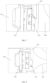
- the supporting portion includes a supporting frame 101, a rotating head 102, and a rotating housing 103.
- the supporting frame 101 is a frame structure with a hollow space and serves as a supporting main body of the supporting portion.
- the rotating head 102 is a cylindrical structure and provided at an end of the supporting frame 101 facing the operating end, and serves as a contact end between the supporting portion and the interface portion.
- the rotating housing 103 covers the rotating head 102 and the interface portion and used to rotate relative to the supporting frame 101, and an opening k of the rotating housing 103 is matched with an outer-ring surface of the cylindrical structure of the rotating head 102.
- the rotating housing 103 is usually a combination of two symmetrical shell structures. FIG. 1 only shows half of the shell structure, which is half of the rotating housing 103.
- the supporting frame 101 is the main structure of the supporting portion, which is a supporting skeleton with a hollow space and a plurality of different setting positions.
- the driving portion, the interface portion, and the detecting portion may be attached to the supporting skeleton and provided at different setting positions to achieve structural integration of the supporting skeleton.
- the rotating head 102 as the end head of the supporting frame 101, is provided to face the interface portion.
- the outer surface of the rotating head 102 is a smooth cylindrical surface (i.e. the outer-ring surface).
- the size of the opening k of the rotating housing 103 may be matched with the size of the cylindrical surface.
- the opening k of the rotating housing 103 and the rear edge of the rotating head 102 facing the supporting frame 101 are cooperated provided.
- the two symmetrical sub-shells of the rotating housing 103 are cooperated with each other to cover the main bodies of the interface portion and the rotating head 102, so that the rotating housing 103 may both protect and isolate the deflection detector.
- the driving portion includes a switching component and a motor component.
- the switching component is opposite to the rotating housing 103, provided on the supporting frame 101, and serves as a driving switch for the driving portion when the switching component is in contact with the rotating housing 103.
- the motor component is electrically connected to the switching component, provided in an accommodating space of the supporting frame 101, and used to provide the driving force in response to a driving switch action of the switching component, so as to provide the rotation action to the interface portion.
- the driving switch of the driving portion is achieved through the switching component.
- the rotating housing 103 may be in contact with the switching component and trigger the driving switch by rotating the rotating housing 103, so that the switching component generates a circuit current signal that controls the motor rotation direction of the motor component via triggering.
- the motor component may drive and rotate the motor in response to the circuit current signal, as well as provide the driving force output to perform the rotation action output. Therefore, the driving portion is mainly used to provide the power for the deflection operation in response to the deflection operation trigger.
- the driving portion serves as the main power source for the deflection detector.
- the switching component includes a switching element 211 and a circuit board 212.
- the switching element 211 is arranged opposite to the opening k of the rotating housing 103 and serves as a contact element of the driving switch.
- the circuit board 212 is provided on a side of the switching element 211, embedded on the supporting frame 101, electrically connected to the motor component, and used to generate an electrical signal for controlling a motor rotation direction of the motor component.
- the switching element 211 is provided on the circuit board 212 through a fixed element.
- the switching element 211 is sheathed in the fixed element, and may enter or exit the fixed element relative to the surface of the fixed element.
- elastic elements such as a spring may be provided in the fixed element, so that when the switching element 211 is compressed by the external force, the switching element 211 may compress the elastic element and enter the fixed element. When the external force is released, the switching element 211 may undergo elastic recovery by the elastic force of the elastic element and exit the fixed element.
- the fixed element may be fixed on the circuit board 212 through methods such as welding.
- the circuit board 212 is electrically connected to the switching element 211.
- the circuit board 212 may generate an electrical signal due to the entry or exit of the switching element 211 from the fixed element, and the electrical signal is transmitted to the motor component of the driving portion, so that the motor component of the driving portion drives and rotates the motor in a specific rotation direction in response to the electrical signal, as well as provides the driving force output to perform the rotation action output.
- the specific size of the circuit board 212 may be only 7mm * 5mm.
- the circuit board 212 is installed on the central skeleton of the supporting frame 101 in a fastening manner, which has a reliable structural design, so that the circuit board 212 transmits the electrical signal through flexible circuits.
- the rotating housing 103 includes a semi-ring convex portion 131 provided on the rotating housing 103 along an outer edge of the opening k of the rotating housing 103 and opposite to the switching element 211, and two end portions of the semi-ring convex portion 131 have sloping surfaces.
- the switching element 211 triggers an electrical contact on the circuit board 212 to generate the electrical signal for controlling the motor rotation direction of the motor component.
- the semi-ring convex portion 131 Since the outer edge of the opening k of the rotating housing 103 is provided with a semi-ring convex structure as a semi-ring convex portion 131, the semi-ring convex portion 131 is protruded on the edge of the opening k and occupies half of the edge of the opening k.
- the semi-ring convex portion 131 may be in contact with the switching element 211 fixed on the circuit board 212 within a specific rotation range, and compress the switching element 211, so that the switching element 211 triggers the circuit board 212 to generate the above-described electrical signal.
- the semi-ring convex portion 131 is not in contact with the switching element 211 within a rotation range of 0° to 180°.
- the switching element 211 may not trigger the circuit board 212 to generate the above-described electrical signal.
- the rotating housing 103 continues to rotate, and within the corresponding rotation range of 180° to 360°, the switching element 211 is in contact with the semi-ring convex portion 131.
- the semi-ring convex portion 131 compresses the switching element 211, so that the switching element 211 triggers the circuit board 212 to generate the above-described electrical signal.
- the motor may be controlled to rotate in a specific direction.
- the above-described electrical signal generated by the contact or detachment between the semi-ring convex portion 131 and the switching element 211 to control the motor rotation direction of the motor component may be used only to define the motor rotation direction, which is a rotation control electrical signal.
- the electrical signal generated by the contact is used to define the clockwise rotation of the motor when it rotates, while the electrical signal generated by the detachment is used to define the counterclockwise rotation of the motor when it rotates.
- the rotation drive of the motor may be specifically achieved through the control circuit of other control buttons, that is, in the case of contact or detachment between the semi-ring convex portion 131 and the switching element 211, the motor may still be in a stationary state without receiving the control driving signal, and may not rotate to output the driving force.
- a further electrical signal may be generated when there is no contact between the switching element 211 and the semi-ring convex portion 131 within the rotation range of 0° to 180° as described above.
- the further electrical signal may be of the same magnitude and opposite polarity as the electrical signal used to control the rotation of the motor of the motor component, so as to define the reverse rotation of the motor of the motor component.
- the electrical signals for different motor rotation directions define a forward rotation or reverse rotation of the motor component, and then the interface portion is driven to perform forward or backward linear movement along the axial direction z relative to the supporting portion when the motor rotates, achieving a change in the deflection direction of the operating end such as the jaw.
- two end surfaces of the semi-ring convex portion 131 facing the switching element 211 are provided as inclined surfaces, so that when the semi-ring convex portion 131 rotates to the position of the switching element 211, the semi-ring convex portion 131 may be in buffered contact with the switching element 211 without collision, avoiding damage to the semi-ring convex portion 131 and the switching element 211.
- the outer surface of the corresponding switching element 211 in contact with the semi-ring convex portion 131 is provided as an arc-shaped outer surface, so that the inclined end surface and the contact plane of the semi-ring convex portion 131 are in contact with and presses the switching element 211 in a tangential direction, thereby better protecting the contact structure of the two and extending the service life of the switch while ensuring the contact effect.
- the machining and assembly tolerances between the switching element 211 and the semi-ring convex portion 131 are included within the range of the switch triggering stroke, ensuring that the switch may be effectively triggered and may not be damaged.
- the motor component includes a motor unit 221 and a gear unit 222.
- the motor unit 221 has an output motor and used to control the output motor to rotate according to the electrical signal for the motor rotation direction, so as to provide the driving force.
- the gear unit 222 is in transmission connection with the motor unit 221 and used to convert the driving force into the rotation action.
- the output motor may output forward or reverse rotation actions according to the electrical signals for different motor rotation directions when controlled to rotate, so as to provide forward or reverse driving force, so that the interface portion performs forward or backward linear movement along the axial direction z relative to the supporting portion when receiving and converting the rotation action provided by the driving force.
- the gear unit 222 and the motor unit 221 are provided on the supporting frame 101.
- the gear unit 222 is in transmission connection with the motor unit 221.
- Such transmission connection refers to that, the output shaft of the motor unit 221 serves as a fixed shaft of the transmission gear of the gear unit 222 to drive the transmission gear to rotate, thereby driving the other gears of the gear unit 222 to rotate, ultimately achieving the rotation of the output shaft 2221 of the gear unit 222.
- the output shaft 2221 of the gear unit 222 is rotated connected to the interface portion by penetrating the rotating head 102 provided on the supporting frame 101, so that when the output shaft 2221 rotates, the interface portion is driven to perform forward or backward linear movement along the axial direction z relative to the supporting portion.
- the interface portion includes an interface seat 301 and a transmitter 302.
- the interface seat 301 is in transmission connection with the gear unit 222 of the motor component and used to convert the rotation action of the driving portion into the linear movement action along the axial direction.
- the transmitter 302 has an end connected to the interface seat 301 and the other end connected to the operating end, and the transmitter is used to convert the linear movement action of the interface seat 301 into the deflection action of the operating end.
- the output shaft 2221 of the gear unit 222 is rotationally connected to the fixed block 311 provided on the interface seat 301 by penetrating the rotating head 102 provided on the supporting frame 101. That is, the output shaft 2221 may rotate relative to the fixed block 311 along the shaft hole in the axial direction z.
- the outer surface of the output shaft 2221 is provided with threads, and the inner surface of the shaft hole of the fixed block 311 has matching threads, resulting in the relative rotation between the output shaft 2221 and the fixed block 311.
- the overall interface seat may perform the forward and backward linear movement along the axial direction z relative to the supporting frame 101.
- the interface seat performs the forward linear movement, expanding the distance between the interface seat 301 and the supporting frame 101.
- the interface seat 301 performs the backward linear movement, reducing the distance between the interface seat 301 and the supporting frame 101, so as to achieve the conversion of the rotational output action of the motor component into the linear forward and backward movement action.
- the interface seat 301 is actively connected to the transmitter 302.
- the transmitter 302 may be connected to the operating end through a deflection rod.
- the transmitter 302 transmits the action of the forward and backward movement to the operating end, so that the operating end converts the action of the forward and backward movement into a forward or reverse deflection action.
- the deflection angle of the deflection action is controlled according to the distance of the forward and backward movement.
- the detecting portion includes a thimble component 401 provided in a fixed hole g of the interface seat 301 and used to detect the movement position of the linear movement action of the interface portion along the axial direction relative to the supporting portion.
- the thimble component 401 includes a plurality of thimbles 411, a thimble sleeve 412, and a fixed sleeve 413.
- the plurality of thimbles 411 are in contact with electrical contacts of the supporting portion, and different detection signals are formed in response to electrical contacts at different positions being detected, and the movement position is fed back using the detection signal.
- the thimble sleeve 412 is sheathed the plurality of thimbles 411, and used to provide attachment positions for the plurality of thimbles 411.
- the fixed sleeve 413 is sheathed the thimble sleeve 412, provided in the fixed hole g of the interface seat 301, matched with the fixed hole g, and used to fix the thimble sleeve 412 sheathed the plurality of thimbles 411 in the fixed hole g.
- a smooth moving surface m is provided on a symmetrical ring surface of the interface seat 301 relative to the fixed block 311.
- the moving surface m is a plane.
- the plane is provided with the fixed hole g at an edge of the interface seat 301 facing the rotating head 102, so as to fix the thimble component 401 through the fixed hole and ensure that the thimble component 401 may perform a more accurate detection response to the distance of the forward and backward linear movement of the interface seat 301.
- the moving surface m may also be used for the rotation limit function of the interface seat 301, preventing the interface seat 301 from rotating with the rotation of the output shaft 2221 and ensuring that the interface seat 301 may generate relative linear movement.
- the heads of the plurality of thimbles 411 of the thimble component 401 may protrude outward relative to the moving surface m.
- the thimble 411 may be a spring thimble.
- the number of thimbles 411 may be at least two, so that the structural stability of the thimble component 411 is improved while ensuring accurate detection, thereby extending the service life of the thimble component.
- the structure of the thimble component 401 is designed to be smaller, more stable and reliable, and have a longer lifespan, through the structure cooperation of the thimble sleeve 412 with the plurality of thimbles 411, as well as the structure cooperation of the fixed sleeve 413 with the thimble sleeve 412 having the plurality of thimbles 411 and the fixed hole g.
- the supporting portion further includes a limiting plate 104 provided on an edge of an end surface of the rotating head 102 facing the interface portion and corresponding to the fixed hole g of the interface seat 301.
- a rear end electrical contact group, a zero position electrical contact group, and a front end electrical contact group are provided on a surface of the limiting plate 104 facing the interface seat 301, and movement position detections on a rear end position, a zero position, and a front end position of the interface portion relative to the supporting portion are achieved when the rear end electrical contact group, the zero position electrical contact group, and the front end electrical contact group are in contact with the plurality of thimbles 411 of the thimble component 401.
- the inner surface of the limiting plate 104 corresponding to the moving surface m of the interface seat 301 may achieve relative movement and rotation limit between the limiting plate 104 and the interface seat 301. That is, after the interface seat 301 is driven by the rotation of the output shaft 2221 as described above, the limiting plate 104 fixed on the end surface of the rotating head 102 may limit the rotation of the interface seat 301 by cooperating with the moving surface m, so that the interface seat 301 may only move in a straight line along the axial direction z, achieving the linear movement of the interface seat 301 relative to the limiting plate 104.
- a zero position electrical contact group is provided at the center position on the inner surface of the limiting plate 104, which has the same number of electrical contacts as the plurality of thimbles 411 of the thimble component 401.
- the zero position electrical contact group may serve as a starting position of the interface seat 301 relative to the limiting plate 104.
- the interface seat 301 moves forward towards the operating end relative to the limiting plate 104, the thimble component 401 leaves the starting position and approaches the front end electrical contact group.
- the front end electrical contact group may be used as the front end limit of the interface seat 301 relative to the limiting plate 104, that is, the interface seat 301 cannot continue to move forward relative to the limiting plate 104, which adds the maximum forward deflection detection for the deflection operation.
- the rear end electrical contact group may be used as the rear end limit of the interface seat 301 relative to the limiting plate 104, that is, the interface seat 301 cannot continue to move backward relative to the limiting plate 104, which adds the maximum reverse deflection detection for the deflection operation.
- the size of the limiting plate 104 may be 4mm * 17mm, extending 16.5mm forward from the bottom of the supporting frame 101.
- the bottom of the interface seat 301 is designed for cooperating the plane m with the inner surface of the limiting plate 104 to perform linear movement and rotation limit.
- the middle of the interface seat 301 may be hollowed out, which may be used to fix structures, such as a pin connection piece and a thimble shim, for outputting the thimble detection signal.
- the electrical contacts of the limiting plate 104 have a certain width, so that the contact between the thimble 411 and the electrical contacts is maintained as an edge contact, thereby ensuring the accuracy of detection during movement and avoiding poor contact situations.
- the left and right displacement deviation for the left and right deflection of the deflection detection contact there is a forward and backward displacement deviation of the thimble 411 on the limiting plate 104, so that the actual contact position between the round head thimble 411 and the edge is not in the center of the limiting plate 104, causing the deflection detection contact to shift left and right (such as 4 mm to the left and 3 mm to the right). Therefore, the above shifting dimensions need to be taken into account to ensure equal travel on both sides.
- the fully single handed operation on the medical device applying the deflection detector may be achieved, with clear steps and prompt information.
- a plurality of deflection buttons with specific distribution designs may be provided on the handle, and when the left hand holds and operates the handle, the operating end deflects to the right when pressing an upper deflection button on the handle; and the operating end deflects to the left when pressing a lower deflection button on the handle; on the contrary, when the right hand holds and operates the handle, the operating end deflects to the left when pressing the upper deflection button on the handle; and the operating end deflects to the right when pressing the lower deflection button on the handle, which achieves single handed hold and control, fully in line with ergonomic design.
- the detecting portion of the present disclosure may actually be expanded to position detections at various angles, achieving various detection functions.
- another aspect of the present disclosure provides a method of controlling the above-described deflection detector, including: steps S901 to S903.
- step S901 in response to a detection instruction, the driving force for achieving the deflection action of the operating end is provided by the driving portion of the deflection detector.
- step S902 the rotation action of the driving portion is converted into the linear movement action along the axial direction using the interface portion of the deflection detector.
- the detecting portion of the deflection detector is controlled to detect the movement position of the linear movement action of the interface portion along the axial direction relative to the supporting portion, so as to complete the detection on the deflection action.
- the detection instruction may be a detection electrical signal generated by the user (such as a surgeon) manually triggering the switch button, for indicating the start of the deflection detection process.
- an embodiment of the present disclosure provides a measurement and control system for implementing the control method.
- the deflection control process of the method of controlling the deflection detector of the new electric stapler is further described in detail as follows.
- the motor By using the motor to control the left or right or up or down deflection of the anvil and the seat of the staple cartridge, and with a function of detecting the angle of the rotating head, the following may be achieved no matter what angle the rotating head is at: when the left hand holds and operates the handle, the jaw deflects to the right when pressing the upper deflection button on the handle; and the jaw deflects to the left when pressing the lower deflection button on the handle; when the right hand holds and operates the handle, the jaw deflects to the left when pressing the upper deflection button on the handle; and the jaw deflects to the right when pressing the lower deflection button on the handle, which is fully in line with ergonomic design.
- the deflection action of the new electric stapler is achieved through two steps. Firstly, the rotating housing 103 is manually rotated so that the anvil and the seat of the staple cartridge move in a circular motion at any angle. Then, the motor component is used to drive the anvil and the seat of staple cartridge to deflect to reach the surgical position.
- the new electric stapler has a function of detecting the rotation position.
- the circuit board 212 for recognizing the rotation direction is fixedly installed on the supporting frame 101.
- the switching element 211 for detecting the rotation direction is provided on the circuit board 212.
- the rotating housing 103 rotates, the rotating housing 103 is not in contact the switching element 211 within the range of 0° to 180°, and there is no signal output from the switching element 211.
- the switching element 211 is triggered by the rotating housing 103 through the inclined surface, and the circuit board 212 is triggered by the switching element 211.
- a trigger signal is output through the circuit board 212 to complete the driving excitation function.
- the motherboard receives the trigger signal to determine the rotation direction of the deflection motor of the motor component.
- the deflection motor drives the fixed block 311 to move forward and backward.
- the rotation of the fixed block 311 drives the transmitter 302 to move forward and backward.
- the transmitter 302 drives the deflection rod to move forward and backward.
- the deflection rod drives the middle deflection rod to move forward and backward.
- the middle deflection rod pulls the seat of the staple cartridge to rotate around the upper and lower fixing plates, completing the deflection action of the jaw component.
- the above-described deflection detector of embodiments of the present disclosure adjusts the function of the left lower deflection button or the left upper deflection button through the motherboard, so as to achieve: when the left hand holds and operates, the jaw deflects to the right when pressing the upper deflection button; and the jaw deflects to the left when pressing the lower deflection button; when the right hand holds and operates, the jaw deflects to the left when pressing the upper deflection button; and the jaw deflects to the right when pressing the lower deflection button, which is fully in line with ergonomic design. It may be seen that the above structure may achieve fully single handed operation, with clear steps and prompt information.
- the device Since the device is safe and reliable, a closed-loop control system is adopts, the position detection is added, the deflection process is decomposed, and different software processes are used, the motor torque output is more reasonable and stable, effectively preventing accidental tissue damage and avoiding the risk of expanding the surgical range caused by clamping too thick tissue.
- an electric stapler including the above-described deflection detector 100 and a jaw component 200.
- the above-described deflection detector 100 is used to detect the movement position of the linear movement action of the interface portion along the axial direction relative to the supporting portion.
- the jaw component 200 is in transmission connection with the interface portion of the deflection detector and serves as the operating end to perform the deflection action according to the detection on the movement position.
- FIGS. 1 to 9 the deflection detector and the control method in embodiments of the present disclosure may be referred to FIGS. 1 to 9 above, which will not be repeated here.
- the deflection detector may be applied to a new type of electric endoscope linear cutting stapler for dissection, resection, and/or establishment of anastomosis, which is mainly suitable for operations of open or minimally invasive general surgery, obstetrics and gynecology, urology, thoracic surgery, and pediatric surgery.
- the deflection detector may be used in cooperation with anastomosis lines or tissue support materials, and may also be used for dissection and resection of liver parenchymal tissue (liver vascular system and biliary structure), pancreas, kidney, and spleen.
- the electric endoscope linear cutting stapler includes the body and component parts, and is a disposable product that may only be used in one surgery. Due to the disposable nature of the electric endoscope linear cutting stapler, cross infection during surgery is avoided.
- Another aspect of the present disclosure provides a medical device, including the above-described deflection detector. Therefore, an electronic limit position detection may be added on the premise of having mechanical limits, so that the jaw component may stop deflecting before hitting the mechanical limit portion when performing the deflection operation, effectively preventing the deflection impact.
- the deflection process does not require manual force, the deflection direction is stable which is not limited by the position of the jaw, and continuous angle rotation may be achieved. The deflection direction and angle meet the doctor's expectations, and fully single handed operation may be achieved.
Landscapes
- Health & Medical Sciences (AREA)
- Surgery (AREA)
- Life Sciences & Earth Sciences (AREA)
- Engineering & Computer Science (AREA)
- General Health & Medical Sciences (AREA)
- Heart & Thoracic Surgery (AREA)
- Medical Informatics (AREA)
- Molecular Biology (AREA)
- Animal Behavior & Ethology (AREA)
- Nuclear Medicine, Radiotherapy & Molecular Imaging (AREA)
- Public Health (AREA)
- Veterinary Medicine (AREA)
- Biomedical Technology (AREA)
- Pathology (AREA)
- Oral & Maxillofacial Surgery (AREA)
- Robotics (AREA)
- Physics & Mathematics (AREA)
- General Physics & Mathematics (AREA)
- Apparatus For Radiation Diagnosis (AREA)
- Mechanical Control Devices (AREA)
- Surgical Instruments (AREA)
Applications Claiming Priority (2)
| Application Number | Priority Date | Filing Date | Title |
|---|---|---|---|
| CN202111146884.8A CN113842181B (zh) | 2021-09-26 | 2021-09-26 | 偏转检测结构及其控制方法,电动吻合器和医疗设备 |
| PCT/CN2022/109114 WO2023045562A1 (zh) | 2021-09-26 | 2022-07-29 | 偏转检测结构及其控制方法、电动吻合器和医疗设备 |
Publications (2)
| Publication Number | Publication Date |
|---|---|
| EP4406493A1 true EP4406493A1 (de) | 2024-07-31 |
| EP4406493A4 EP4406493A4 (de) | 2025-07-23 |
Family
ID=78976889
Family Applications (1)
| Application Number | Title | Priority Date | Filing Date |
|---|---|---|---|
| EP22871620.5A Pending EP4406493A4 (de) | 2021-09-26 | 2022-07-29 | Ablenkungsdetektionsstruktur und steuerungsverfahren dafür, elektrisches klammergerät und medizinische vorrichtung |
Country Status (4)
| Country | Link |
|---|---|
| US (1) | US12324646B2 (de) |
| EP (1) | EP4406493A4 (de) |
| CN (1) | CN113842181B (de) |
| WO (1) | WO2023045562A1 (de) |
Families Citing this family (2)
| Publication number | Priority date | Publication date | Assignee | Title |
|---|---|---|---|---|
| CN113842181B (zh) * | 2021-09-26 | 2023-09-29 | 赛诺微医疗科技(浙江)有限公司 | 偏转检测结构及其控制方法,电动吻合器和医疗设备 |
| CN116058897A (zh) * | 2022-11-23 | 2023-05-05 | 以诺康医疗科技(苏州)有限公司 | 具有双检测功能的智能吻合器及检测方法 |
Family Cites Families (20)
| Publication number | Priority date | Publication date | Assignee | Title |
|---|---|---|---|---|
| JPS5878639A (ja) | 1981-11-04 | 1983-05-12 | オリンパス光学工業株式会社 | 内視鏡 |
| US20090090763A1 (en) * | 2007-10-05 | 2009-04-09 | Tyco Healthcare Group Lp | Powered surgical stapling device |
| US9782130B2 (en) * | 2004-05-28 | 2017-10-10 | St. Jude Medical, Atrial Fibrillation Division, Inc. | Robotic surgical system |
| CN200980692Y (zh) * | 2006-08-08 | 2007-11-28 | 蓝正平 | 自锁皮肤吻合器 |
| US8641663B2 (en) * | 2008-03-27 | 2014-02-04 | St. Jude Medical, Atrial Fibrillation Division, Inc. | Robotic catheter system input device |
| JP5336760B2 (ja) * | 2008-05-01 | 2013-11-06 | オリンパスメディカルシステムズ株式会社 | 内視鏡システム |
| GB201119734D0 (en) * | 2011-11-16 | 2011-12-28 | Gyrus Medical Ltd | Surgical instrument |
| WO2013122792A2 (en) * | 2012-02-14 | 2013-08-22 | Ethicon-Endo Surgery, Inc. | Linear stapler |
| CN104783844B (zh) * | 2015-01-22 | 2017-05-17 | 天津手智医疗科技有限责任公司 | 一种智能化微创手术器械 |
| CN106491211B (zh) * | 2016-09-30 | 2019-02-12 | 江苏风和医疗器材股份有限公司 | 一种吻合器击发力检测装置 |
| US10779825B2 (en) * | 2017-12-15 | 2020-09-22 | Ethicon Llc | Adapters with end effector position sensing and control arrangements for use in connection with electromechanical surgical instruments |
| US11452528B2 (en) * | 2019-04-30 | 2022-09-27 | Cilag Gmbh International | Articulation actuators for a surgical instrument |
| CN211723295U (zh) * | 2019-12-13 | 2020-10-23 | 赛诺微医疗科技(浙江)有限公司 | 吻合器末端执行器、其偏转装置及采用其的吻合器 |
| US11553937B2 (en) * | 2019-12-30 | 2023-01-17 | Biosense Webster (Israel) Ltd. | Deflection mechanism of an ear-nose-throat tool |
| CN111761609B (zh) * | 2020-07-08 | 2022-06-03 | 天津大学 | 基于接触辅助结构的柔性连续体机器人 |
| CN212699005U (zh) * | 2020-08-07 | 2021-03-16 | 山东威瑞外科医用制品有限公司 | 一种电动吻合器 |
| CN111973243B (zh) * | 2020-09-15 | 2022-09-27 | 赛诺微医疗科技(浙江)有限公司 | 一种外科切割缝合器械 |
| CN111904515B (zh) * | 2020-09-15 | 2023-03-28 | 赛诺微医疗科技(浙江)有限公司 | 外科器械及其执行器的位置识别与控制装置及方法 |
| CN112617937B (zh) * | 2020-12-29 | 2022-05-17 | 美科特医疗科技(苏州)有限公司 | 一种吻合器套管组件 |
| CN113842181B (zh) * | 2021-09-26 | 2023-09-29 | 赛诺微医疗科技(浙江)有限公司 | 偏转检测结构及其控制方法,电动吻合器和医疗设备 |
-
2021
- 2021-09-26 CN CN202111146884.8A patent/CN113842181B/zh active Active
-
2022
- 2022-07-29 EP EP22871620.5A patent/EP4406493A4/de active Pending
- 2022-07-29 WO PCT/CN2022/109114 patent/WO2023045562A1/zh not_active Ceased
- 2022-07-29 US US18/695,161 patent/US12324646B2/en active Active
Also Published As
| Publication number | Publication date |
|---|---|
| US12324646B2 (en) | 2025-06-10 |
| US20240390091A1 (en) | 2024-11-28 |
| EP4406493A4 (de) | 2025-07-23 |
| CN113842181A (zh) | 2021-12-28 |
| CN113842181B (zh) | 2023-09-29 |
| WO2023045562A1 (zh) | 2023-03-30 |
Similar Documents
| Publication | Publication Date | Title |
|---|---|---|
| EP4406493A1 (de) | Ablenkungsdetektionsstruktur und steuerungsverfahren dafür, elektrisches klammergerät und medizinische vorrichtung | |
| US12433627B2 (en) | Surgical instrument soft stop | |
| US20230270438A1 (en) | Articulatable surgical instruments with conductive pathways for signal communication | |
| JP2024015267A (ja) | 専用関節運動モータ構成を有する関節運動可能なモータ電動外科用器具 | |
| CN215273148U (zh) | 超声手术刀手柄与超声手术刀 | |
| JP2009233329A (ja) | 超音波処置装置 | |
| JP2007275291A (ja) | 超音波処置装置 | |
| CN206586996U (zh) | 线性切割吻合器 | |
| CN111214266A (zh) | 用于电动吻合器的击发与弯转切换装置及其电动吻合器 | |
| AU2021375720B2 (en) | Ultrasonic scalpel handle, ultrasonic scalpel and ultrasonic scalpel system | |
| CN116807543A (zh) | 一种电动吻合器 | |
| EP3831312B1 (de) | Chirurgisches instrument und lineares klammergerät | |
| CN106344093B (zh) | 线性切割吻合器 | |
| CN218960824U (zh) | 一种具有手动回刀机构的腔镜切割吻合器 | |
| CN206809304U (zh) | 线性切割吻合器 | |
| US20220022867A1 (en) | Powered surgical instrument | |
| CN219720775U (zh) | 一种电动吻合器 | |
| CA3122139C (en) | Circular stapler | |
| CN112690891A (zh) | 一种可实现左右弯转的电外科器械 | |
| CN223746419U (zh) | 腔镜吻合器 | |
| US12426881B2 (en) | Powered actuation assist for an open linear stapling device | |
| CN114831682A (zh) | 电动吻合器 | |
| CN222172180U (zh) | 击发机构及电动吻合器 | |
| CN118267077B (zh) | 集成有超声刀和单极电刀的手术器械 | |
| CN216495514U (zh) | 一种自动触发的超声外科器械 |
Legal Events
| Date | Code | Title | Description |
|---|---|---|---|
| STAA | Information on the status of an ep patent application or granted ep patent |
Free format text: STATUS: THE INTERNATIONAL PUBLICATION HAS BEEN MADE |
|
| PUAI | Public reference made under article 153(3) epc to a published international application that has entered the european phase |
Free format text: ORIGINAL CODE: 0009012 |
|
| STAA | Information on the status of an ep patent application or granted ep patent |
Free format text: STATUS: REQUEST FOR EXAMINATION WAS MADE |
|
| 17P | Request for examination filed |
Effective date: 20240422 |
|
| AK | Designated contracting states |
Kind code of ref document: A1 Designated state(s): AL AT BE BG CH CY CZ DE DK EE ES FI FR GB GR HR HU IE IS IT LI LT LU LV MC MK MT NL NO PL PT RO RS SE SI SK SM TR |
|
| DAV | Request for validation of the european patent (deleted) | ||
| DAX | Request for extension of the european patent (deleted) | ||
| A4 | Supplementary search report drawn up and despatched |
Effective date: 20250623 |
|
| RIC1 | Information provided on ipc code assigned before grant |
Ipc: A61B 17/072 20060101AFI20250616BHEP Ipc: A61B 17/3209 20060101ALI20250616BHEP Ipc: A61B 90/00 20160101ALI20250616BHEP Ipc: G01B 21/22 20060101ALI20250616BHEP Ipc: A61B 17/00 20060101ALN20250616BHEP |