EP4405539B1 - Fliesennivelliervorrichtung - Google Patents
Fliesennivelliervorrichtung Download PDFInfo
- Publication number
- EP4405539B1 EP4405539B1 EP22777717.4A EP22777717A EP4405539B1 EP 4405539 B1 EP4405539 B1 EP 4405539B1 EP 22777717 A EP22777717 A EP 22777717A EP 4405539 B1 EP4405539 B1 EP 4405539B1
- Authority
- EP
- European Patent Office
- Prior art keywords
- rotating member
- pressure body
- external rotating
- fact
- shaped
- Prior art date
- Legal status (The legal status is an assumption and is not a legal conclusion. Google has not performed a legal analysis and makes no representation as to the accuracy of the status listed.)
- Active
Links
Images


Classifications
-
- E—FIXED CONSTRUCTIONS
- E04—BUILDING
- E04F—FINISHING WORK ON BUILDINGS, e.g. STAIRS, FLOORS
- E04F21/00—Implements for finishing work on buildings
- E04F21/0092—Separate provisional spacers used between adjacent floor or wall tiles
-
- E—FIXED CONSTRUCTIONS
- E04—BUILDING
- E04F—FINISHING WORK ON BUILDINGS, e.g. STAIRS, FLOORS
- E04F15/00—Flooring
- E04F15/02—Flooring or floor layers composed of a number of similar elements
- E04F15/02005—Construction of joints, e.g. dividing strips
- E04F15/02022—Construction of joints, e.g. dividing strips with means for aligning the outer surfaces of the flooring elements
-
- E—FIXED CONSTRUCTIONS
- E04—BUILDING
- E04F—FINISHING WORK ON BUILDINGS, e.g. STAIRS, FLOORS
- E04F21/00—Implements for finishing work on buildings
- E04F21/20—Implements for finishing work on buildings for laying flooring
- E04F21/22—Implements for finishing work on buildings for laying flooring of single elements, e.g. flooring cramps ; flexible webs
Definitions
- the invention relates to a tile levelling device used on a surface to level at least two adjacent tiles.
- the said device is of the type comprising a support designed to be positioned between at least two adjacent tiles and which, in addition to fulfilling a spacing function, is also equipped with a base envisaged to be placed under the two tiles and an elongated body or rod, which extends vertically from the base in a perpendicular manner thereto.
- the body has an elongated or stem form and is equipped with gripping means which form a coaxial connection, by means of a thread, with a pressure body.
- the said body is endowed with a lower edge endowed with a flat support surface intended to operate through contact with parts of the upper surfaces of at least two adjacent tiles.
- the task of the said flat support surface which is arranged perpendicular to the central axis of the pressure body, is to perform the levelling, i.e. aligning the upper flat surfaces of the two or more adjacent tiles lying in the same plane when the said support surface is pushed against the upper surfaces of the adjacent tiles, exploiting the counteraction applied by the base to the lower surfaces of the said tiles.
- This operation is performed using the screw connection, whereby the pressure body is screwed onto the thread with which the elongated body or rod is equipped, with the result that the support surface of the pressure body ends up in contact and pushing against the flat upper surfaces of adjacent tiles.
- EP3567183A1 discloses a device according to the preamble of claim 1.
- the main object of the present invention is to further speed up the entire levelling operation which, according to prior art, is strongly conditioned by the lengthy screwing and unscrewing times.
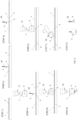
- 1 denotes the individual tiles used to make a floor.
- the tiles 1 are laid on a surface with a layer of glue 2 interposed therebetween.
- each levelling device is used to act between at least two adjacent tiles 1 and comprises a support which is designed to be inserted between at least two adjacent tiles 1 and is endowed with a base 5, which is positioned under the two adjacent tiles and embedded in the layer of glue 2.
- Part of the support is an elongated body or rod 4 which extends orthogonally from the base 5 and is equipped with means for the gripping thereof from the outside, which essentially consist of an external thread 40.
- the external thread 40 is featured and sized so that a pressure body 3 couples therewith in a removable manner by means of a tapped hole 33 with which the said pressure body is endowed.
- the pressure body 3 has a lower edge 30 which is in turn provided with a flat support surface 31 intended to operate in contact with at least part of the upper surfaces of the adjacent tiles 1, either with or without a scratch guard plate interposed therebetween.
- the support surface 31 is arranged perpendicular to the central axis of the pressure body 3, which is overall axially symmetric.
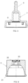
- the pressure body 3 may be coaxially coupled to an external rotating member 7 designed to be driven by an external screwing tool 10 whose task is to generate, on command, the rotation thereof in both directions.
- the pressure body 3 may be coaxially coupled to the external rotating member 7 by means of a coupling achieved by magnetic attraction.
- the external rotating member 7 is, in turn, equipped with a tang 9 for coupling with the external screwing tool 10.
- the pressure body 3 is cylindrical overall and is equipped with protruding ribs 35 on part of the external surface thereof. It is also equipped with an annular insert 32, made of a ferrous or ferromagnetic material, arranged integrally therewith and coaxially on part of the side walls thereof.
- the external rotating member 7 have an axially symmetrical bell shape, shaped to accommodate - perfectly centred therewithin - at least part of the upper portion of the pressure body (3), and comprises, integrally coupled with at least part of the internal surface thereof, at least one insert consisting of a magnet 8 configured in an annular shape.
- the task of the magnet 8 is to provide magnetic attraction to attract the annular insert made of a ferromagnetic material 32 with which the single pressure body 3 is equipped
- the mutual arrangement of the materials used to provide the magnetic attraction between the pressure body 3 and the external rotating member 7 may be swapped and therefore a magnet may be coupled with the pressure body 3 instead of the ferromagnetic material and the external rotating member 7 may be coupled with a ring made of ferromagnetic material or the like instead of the magnet 8.
- the elongated body 4 is positioned in a vertical arrangement, so that the base 5 thereof is inserted into the layer of glue 2 underneath the edge of the said tile. A new tile 1 is then laid alongside the previous one. The lower part of the elongated body 4 keeps the edge of the new tile away from the edge of the tile laid previously.
- the tile layer then acts by preparing the assembly consisting of the pressure body 3 magnetically constrained to an external rotating member 7 and then coupling the tang 9 with a screwing tool 10. Activation of the screwing tool 10 screws the pressure body 3 onto the external thread 40 of the elongated body or rod 4 until the lower supporting surface 31 is forced to operate through contact with the upper surfaces of the two tiles 1.
- the action just described is the result of the pressure applied by the pressure body 3 to the upper surfaces of the tiles 1 through the counteraction applied by the base 5 to the lower surfaces of the said tiles 1.
- the elongated body 4 may be broken - by hammering the pressure body (3 (step 7)) - and detached therefore from the base 5, which remains in position under the adjacent tiles 1.
- Unscrewing can be performed quickly using the same screwing tool 10 (see steps 8 and 9).
- the magnetic attraction exerted between the magnet 8 fixed to the external rotating member 7 and the annular insert 32 made of ferromagnetic material makes the pressure body 3 integral with the said external rotating member 7, thereby ensuring easy manoeuvrability of the assembly which is further increased by the possibility of use thereof in conjunction with a screwing tool.
Landscapes
- Engineering & Computer Science (AREA)
- Architecture (AREA)
- Civil Engineering (AREA)
- Structural Engineering (AREA)
- Finishing Walls (AREA)
- Floor Finish (AREA)
- Devices For Post-Treatments, Processing, Supply, Discharge, And Other Processes (AREA)
- Soil Working Implements (AREA)
Claims (7)
- Vorrichtung zum Höhenausgleich bei Fliesen, die auf einer Ebene verwendet wird, um mindestens nebeneinander befindliche Fliesen auszugleichen, einschließlich:- einer Halterung, die geeignet ist, zwischen mindestens zwei nebeneinander befindlichen Fliesen (1) platziert zu werden, und mit einem Fuß (5) versehen ist, der unter den mindestens zwei Fliesen platziert werden kann; einen länglichen Körper oder Schaft (4), der sich rechtwinklig vom Fuß (5) erstreckt und mit Hilfsmitteln ausgestattet ist, die das Greifen ermöglichen, bestehend aus einem Außengewinde (40);- einem Druck- (3) und Höhenausgleichselement, das geeignet ist, mit Hilfe des länglichen Körpers oder Schaftes (4) lösbar mit der Halterung verbunden zu werden, das über eine Struktur mit einer Unterkante (30) verfügt, die mit einer ebenen Auflagefläche (31) versehen ist, die dazu dient, bei Berührung mindestens einer der Oberseiten von mindestens zwei nebeneinander liegenden Fliesen (1, ) einzuwirken, wobei diese Auflagefläche (31) senkrecht zur Mittelachse des Druckelements (3) angeordnet ist;- Dadurch gekennzeichnet, dass das Druckelement (3) koaxial mit einem externen rotierenden Teil (7) gekoppelt werden kann, das die Funktion hat, auf Befehl eine Drehung in beide Richtungen hervorzurufen.
- Vorrichtung gemäß Patentanspruch 1, die dadurch gekennzeichnet ist, dass das Druckelement (3) mittels einer durch magnetische Anziehung erfolgten Kopplung koaxial an ein externes rotierendes Teil (7) gekoppelt werden kann; dieser externe rotierende Teil (7) ist mit einem Zapfen (9) zur Verbindung mit einem externen Schraubwerkzeug (10) ausgestattet.
- Vorrichtung gemäß Patentanspruch 2, die dadurch gekennzeichnet ist, dass das äußere rotierende Teil (7) die axialsymmetrische Form einer Glocke hat, die so geformt ist, dass sie zumindest einen Teil des oberen Teils des Druckelements (3) zentriert aufnehmen kann und umfasst einen mit ihm fest verbundenen Einsatz, an dem zumindest ein Teil seiner Innenfläche aus einem ringförmig ausgebildeten Magneten (8) besteht.
- Vorrichtung gemäß Patentanspruch 3, die dadurch gekennzeichnet ist, dass das Druckelement (3) insgesamt eine zylindrische Form aufweist und mit einem ringförmigen Einsatz (32) aus ferromagnetischem Material versehen ist, der fest und koaxial zu den Seitenwänden dieser Vorrichtung angeordnet ist.
- Vorrichtung gemäß Patentanspruch 4, die dadurch gekennzeichnet ist, dass das äußere rotierende Teil (7) in Form einer axialsymmetrischen Glocke, das fest mit zumindest einem Teil seiner Innenfläche mit mindestens einen Einsatz bestehend aus einem ringförmig ausgebildeten Magneten (8) verbunden ist; der Magnet (8) erfüllt die Aufgabe, die Funktion der magnetischen Anziehungskraft auf den ringförmigen Einsatz aus eisenhaltigem Material oder magnetischem Eisen (32) auszuüben.
- Vorrichtung gemäß Patentanspruch 3, die dadurch gekennzeichnet ist, dass das Druckelement (3) eine insgesamt zylindrische Form aufweist und aus einem magnetischen Material besteht.
- Vorrichtung gemäß Patentanspruch 6, die dadurch gekennzeichnet ist, dass das äußere rotierende Teil (7) in Form einer axialsymmetrischen Glocke aus eisenhaltigem oder magnetischem Material besteht und die Aufgabe erfüllt, die Funktion der magnetischen Anziehung auf das magnetische Material des Druckelements (3), mit dem es gekoppelt ist, auszuüben; das äußere rotierende Teil (7) weist eine axialsymmetrische Form einer Glocke auf, das so geformt ist, dass es zumindest einen Teil des oberen Teils des Druckelements (3) zentriert aufnehmen kann und umfasst einen fest verbundenen Einsatz an zumindest einem Teil seiner Innenfläche, der aus einem ringförmig ausgebildeten Magneten (8) besteht.
Applications Claiming Priority (2)
| Application Number | Priority Date | Filing Date | Title |
|---|---|---|---|
| IT102021000024488A IT202100024488A1 (it) | 2021-09-23 | 2021-09-23 | Dispositivo livellatore per piastrelle |
| PCT/IB2022/058570 WO2023047242A1 (en) | 2021-09-23 | 2022-09-12 | Tile levelling device |
Publications (2)
| Publication Number | Publication Date |
|---|---|
| EP4405539A1 EP4405539A1 (de) | 2024-07-31 |
| EP4405539B1 true EP4405539B1 (de) | 2025-02-19 |
Family
ID=79018685
Family Applications (1)
| Application Number | Title | Priority Date | Filing Date |
|---|---|---|---|
| EP22777717.4A Active EP4405539B1 (de) | 2021-09-23 | 2022-09-12 | Fliesennivelliervorrichtung |
Country Status (8)
| Country | Link |
|---|---|
| US (1) | US20240401349A1 (de) |
| EP (1) | EP4405539B1 (de) |
| CN (1) | CN118119755A (de) |
| CA (1) | CA3232570A1 (de) |
| ES (1) | ES3031687T3 (de) |
| IT (1) | IT202100024488A1 (de) |
| PL (1) | PL4405539T3 (de) |
| WO (1) | WO2023047242A1 (de) |
Families Citing this family (2)
| Publication number | Priority date | Publication date | Assignee | Title |
|---|---|---|---|---|
| IT202300016470A1 (it) * | 2023-08-02 | 2025-02-02 | Dakota Group S A S Di Zeno Cipriani & C | Dispositivo livellatore-spaziatore per piastrelle lastre o simili |
| EP4644638A1 (de) | 2024-04-30 | 2025-11-05 | 7C Srl | Nivelliervorrichtung zum fliesenverlegen |
Citations (12)
| Publication number | Priority date | Publication date | Assignee | Title |
|---|---|---|---|---|
| DE102011051428A1 (de) * | 2010-08-16 | 2012-02-16 | Fliesenwerkstatt Marton Gmbh | Verlegehilfe für dünnschichtige Großformatplatten als Boden- oder Wandbedeckung |
| EP2549030A2 (de) * | 2011-07-19 | 2013-01-23 | Brunoplast di Eleuteri Bruno | Vorrichtung zum korrekten Verlegen von Bodenfliesen |
| WO2014045381A1 (ja) * | 2012-09-20 | 2014-03-27 | 有限会社オーパーツ | 固定装置及び固定装置を用いた施工方法 |
| EP2966238A1 (de) * | 2014-07-11 | 2016-01-13 | FI.R.P. di Fiorese M. e C. s.n.c. | Positioniersystem für abdeckelemente |
| US9279259B1 (en) * | 2015-05-21 | 2016-03-08 | William P. Russo | Tile lippage removal system |
| US20170044779A1 (en) * | 2015-08-13 | 2017-02-16 | Ching-Tien Teng | Tile Leveler |
| WO2018172802A1 (en) * | 2017-03-22 | 2018-09-27 | Krizmanic Davor | A device for laying and leveling ceramic tiles or any other plate-like materials on a flat surface |
| EP3524751A1 (de) * | 2018-02-12 | 2019-08-14 | Solidor Rubber&Products BVBA | Nivelliersystem |
| EP3533951A1 (de) * | 2018-03-01 | 2019-09-04 | Ghelfi S.r.l. | Knopf zur kopplung mit einem fugenabstandshalter bei verlegung der fliesen auf flächen |
| WO2021071456A1 (en) * | 2019-10-08 | 2021-04-15 | Sevinc Murat | Leveling tool for building coating materials |
| WO2021220232A1 (en) * | 2020-04-30 | 2021-11-04 | Dakota Group S.A.S. Di Zeno Cipriani & C. | Leveler for tiles |
| EP4008852A1 (de) * | 2020-12-04 | 2022-06-08 | Raimondi S.p.A. | Stützvorrichtung zur verlegung von fliesen |
Family Cites Families (2)
| Publication number | Priority date | Publication date | Assignee | Title |
|---|---|---|---|---|
| ITUA20163399A1 (it) | 2016-05-12 | 2017-11-12 | Termoplast S R L | Livellatore per piastrelle |
| IT201800005212A1 (it) * | 2018-05-09 | 2019-11-09 | Dispositivo distanziatore livellante |
-
2021
- 2021-09-23 IT IT102021000024488A patent/IT202100024488A1/it unknown
-
2022
- 2022-09-12 ES ES22777717T patent/ES3031687T3/es active Active
- 2022-09-12 US US18/694,689 patent/US20240401349A1/en active Pending
- 2022-09-12 WO PCT/IB2022/058570 patent/WO2023047242A1/en not_active Ceased
- 2022-09-12 CA CA3232570A patent/CA3232570A1/en active Pending
- 2022-09-12 PL PL22777717.4T patent/PL4405539T3/pl unknown
- 2022-09-12 CN CN202280069042.3A patent/CN118119755A/zh active Pending
- 2022-09-12 EP EP22777717.4A patent/EP4405539B1/de active Active
Patent Citations (12)
| Publication number | Priority date | Publication date | Assignee | Title |
|---|---|---|---|---|
| DE102011051428A1 (de) * | 2010-08-16 | 2012-02-16 | Fliesenwerkstatt Marton Gmbh | Verlegehilfe für dünnschichtige Großformatplatten als Boden- oder Wandbedeckung |
| EP2549030A2 (de) * | 2011-07-19 | 2013-01-23 | Brunoplast di Eleuteri Bruno | Vorrichtung zum korrekten Verlegen von Bodenfliesen |
| WO2014045381A1 (ja) * | 2012-09-20 | 2014-03-27 | 有限会社オーパーツ | 固定装置及び固定装置を用いた施工方法 |
| EP2966238A1 (de) * | 2014-07-11 | 2016-01-13 | FI.R.P. di Fiorese M. e C. s.n.c. | Positioniersystem für abdeckelemente |
| US9279259B1 (en) * | 2015-05-21 | 2016-03-08 | William P. Russo | Tile lippage removal system |
| US20170044779A1 (en) * | 2015-08-13 | 2017-02-16 | Ching-Tien Teng | Tile Leveler |
| WO2018172802A1 (en) * | 2017-03-22 | 2018-09-27 | Krizmanic Davor | A device for laying and leveling ceramic tiles or any other plate-like materials on a flat surface |
| EP3524751A1 (de) * | 2018-02-12 | 2019-08-14 | Solidor Rubber&Products BVBA | Nivelliersystem |
| EP3533951A1 (de) * | 2018-03-01 | 2019-09-04 | Ghelfi S.r.l. | Knopf zur kopplung mit einem fugenabstandshalter bei verlegung der fliesen auf flächen |
| WO2021071456A1 (en) * | 2019-10-08 | 2021-04-15 | Sevinc Murat | Leveling tool for building coating materials |
| WO2021220232A1 (en) * | 2020-04-30 | 2021-11-04 | Dakota Group S.A.S. Di Zeno Cipriani & C. | Leveler for tiles |
| EP4008852A1 (de) * | 2020-12-04 | 2022-06-08 | Raimondi S.p.A. | Stützvorrichtung zur verlegung von fliesen |
Also Published As
| Publication number | Publication date |
|---|---|
| CA3232570A1 (en) | 2023-03-30 |
| PL4405539T3 (pl) | 2025-07-21 |
| ES3031687T3 (en) | 2025-07-10 |
| IT202100024488A1 (it) | 2023-03-23 |
| WO2023047242A1 (en) | 2023-03-30 |
| CN118119755A (zh) | 2024-05-31 |
| US20240401349A1 (en) | 2024-12-05 |
| EP4405539A1 (de) | 2024-07-31 |
Similar Documents
| Publication | Publication Date | Title |
|---|---|---|
| EP4405539B1 (de) | Fliesennivelliervorrichtung | |
| TWI856160B (zh) | 異物移除用套筒轉接頭 | |
| CN100527859C (zh) | 具有差动隔离能力的麦克风支撑吊杆运动控制装置及方法 | |
| CN110029802B (zh) | 用于铺设墙面砖、地砖的调平垫片的旋钮 | |
| WO2023148596A1 (en) | Tile levelling device | |
| SE539897C2 (sv) | Förfarande och verktyg för skruvförband | |
| CN203371460U (zh) | 用于夹持紧固件的夹持装置 | |
| US20060236822A1 (en) | Threaded member driver with retention system | |
| US20170072476A1 (en) | Spring Loading Insert | |
| US9931702B2 (en) | Locking drill bushing | |
| CN209585553U (zh) | 一种瓷砖留缝找平器 | |
| US6530719B1 (en) | Gripping and maneuvering apparatus | |
| GB2540826A (en) | Tile leveler | |
| JP3131101U (ja) | 左官用鏝 | |
| KR101530075B1 (ko) | 변속기용 주축 베어링 탈거장치 | |
| CN218747406U (zh) | 一种强磁套筒 | |
| CN220063452U (zh) | 一种用于勘察的取样装置 | |
| CN216372734U (zh) | 一种便于拆卸钢管套的成型模具 | |
| AU2024318198A1 (en) | A levelling and spacing device for tiles, slabs or the like | |
| CN213626540U (zh) | 一种瓷砖找平器 | |
| GB2072783A (en) | Fixing device | |
| JP7322906B2 (ja) | パイプ保持具 | |
| KR20180104407A (ko) | 건축용 고정너트 | |
| CN210650507U (zh) | 一种管路接头安装工装 | |
| EP3698922A1 (de) | Schraubaufsatz |
Legal Events
| Date | Code | Title | Description |
|---|---|---|---|
| STAA | Information on the status of an ep patent application or granted ep patent |
Free format text: STATUS: UNKNOWN |
|
| STAA | Information on the status of an ep patent application or granted ep patent |
Free format text: STATUS: THE INTERNATIONAL PUBLICATION HAS BEEN MADE |
|
| PUAI | Public reference made under article 153(3) epc to a published international application that has entered the european phase |
Free format text: ORIGINAL CODE: 0009012 |
|
| STAA | Information on the status of an ep patent application or granted ep patent |
Free format text: STATUS: REQUEST FOR EXAMINATION WAS MADE |
|
| 17P | Request for examination filed |
Effective date: 20240329 |
|
| AK | Designated contracting states |
Kind code of ref document: A1 Designated state(s): AL AT BE BG CH CY CZ DE DK EE ES FI FR GB GR HR HU IE IS IT LI LT LU LV MC MK MT NL NO PL PT RO RS SE SI SK SM TR |
|
| DAV | Request for validation of the european patent (deleted) | ||
| DAX | Request for extension of the european patent (deleted) | ||
| GRAP | Despatch of communication of intention to grant a patent |
Free format text: ORIGINAL CODE: EPIDOSNIGR1 |
|
| STAA | Information on the status of an ep patent application or granted ep patent |
Free format text: STATUS: GRANT OF PATENT IS INTENDED |
|
| INTG | Intention to grant announced |
Effective date: 20240925 |
|
| GRAS | Grant fee paid |
Free format text: ORIGINAL CODE: EPIDOSNIGR3 |
|
| GRAA | (expected) grant |
Free format text: ORIGINAL CODE: 0009210 |
|
| STAA | Information on the status of an ep patent application or granted ep patent |
Free format text: STATUS: THE PATENT HAS BEEN GRANTED |
|
| AK | Designated contracting states |
Kind code of ref document: B1 Designated state(s): AL AT BE BG CH CY CZ DE DK EE ES FI FR GB GR HR HU IE IS IT LI LT LU LV MC MK MT NL NO PL PT RO RS SE SI SK SM TR |
|
| REG | Reference to a national code |
Ref country code: GB Ref legal event code: FG4D |
|
| REG | Reference to a national code |
Ref country code: CH Ref legal event code: EP |
|
| REG | Reference to a national code |
Ref country code: IE Ref legal event code: FG4D |
|
| REG | Reference to a national code |
Ref country code: DE Ref legal event code: R096 Ref document number: 602022010925 Country of ref document: DE |
|
| REG | Reference to a national code |
Ref country code: NL Ref legal event code: MP Effective date: 20250219 |
|
| PG25 | Lapsed in a contracting state [announced via postgrant information from national office to epo] |
Ref country code: RS Free format text: LAPSE BECAUSE OF FAILURE TO SUBMIT A TRANSLATION OF THE DESCRIPTION OR TO PAY THE FEE WITHIN THE PRESCRIBED TIME-LIMIT Effective date: 20250519 |
|
| PG25 | Lapsed in a contracting state [announced via postgrant information from national office to epo] |
Ref country code: FI Free format text: LAPSE BECAUSE OF FAILURE TO SUBMIT A TRANSLATION OF THE DESCRIPTION OR TO PAY THE FEE WITHIN THE PRESCRIBED TIME-LIMIT Effective date: 20250219 |
|
| REG | Reference to a national code |
Ref country code: ES Ref legal event code: FG2A Ref document number: 3031687 Country of ref document: ES Kind code of ref document: T3 Effective date: 20250710 Ref country code: LT Ref legal event code: MG9D |
|
| PG25 | Lapsed in a contracting state [announced via postgrant information from national office to epo] |
Ref country code: IS Free format text: LAPSE BECAUSE OF FAILURE TO SUBMIT A TRANSLATION OF THE DESCRIPTION OR TO PAY THE FEE WITHIN THE PRESCRIBED TIME-LIMIT Effective date: 20250619 Ref country code: NO Free format text: LAPSE BECAUSE OF FAILURE TO SUBMIT A TRANSLATION OF THE DESCRIPTION OR TO PAY THE FEE WITHIN THE PRESCRIBED TIME-LIMIT Effective date: 20250519 |
|
| PG25 | Lapsed in a contracting state [announced via postgrant information from national office to epo] |
Ref country code: NL Free format text: LAPSE BECAUSE OF FAILURE TO SUBMIT A TRANSLATION OF THE DESCRIPTION OR TO PAY THE FEE WITHIN THE PRESCRIBED TIME-LIMIT Effective date: 20250219 |
|
| PG25 | Lapsed in a contracting state [announced via postgrant information from national office to epo] |
Ref country code: HR Free format text: LAPSE BECAUSE OF FAILURE TO SUBMIT A TRANSLATION OF THE DESCRIPTION OR TO PAY THE FEE WITHIN THE PRESCRIBED TIME-LIMIT Effective date: 20250219 |
|
| PG25 | Lapsed in a contracting state [announced via postgrant information from national office to epo] |
Ref country code: LV Free format text: LAPSE BECAUSE OF FAILURE TO SUBMIT A TRANSLATION OF THE DESCRIPTION OR TO PAY THE FEE WITHIN THE PRESCRIBED TIME-LIMIT Effective date: 20250219 Ref country code: PT Free format text: LAPSE BECAUSE OF FAILURE TO SUBMIT A TRANSLATION OF THE DESCRIPTION OR TO PAY THE FEE WITHIN THE PRESCRIBED TIME-LIMIT Effective date: 20250620 |
|
| PG25 | Lapsed in a contracting state [announced via postgrant information from national office to epo] |
Ref country code: BG Free format text: LAPSE BECAUSE OF FAILURE TO SUBMIT A TRANSLATION OF THE DESCRIPTION OR TO PAY THE FEE WITHIN THE PRESCRIBED TIME-LIMIT Effective date: 20250219 Ref country code: GR Free format text: LAPSE BECAUSE OF FAILURE TO SUBMIT A TRANSLATION OF THE DESCRIPTION OR TO PAY THE FEE WITHIN THE PRESCRIBED TIME-LIMIT Effective date: 20250520 |
|
| PG25 | Lapsed in a contracting state [announced via postgrant information from national office to epo] |
Ref country code: SE Free format text: LAPSE BECAUSE OF FAILURE TO SUBMIT A TRANSLATION OF THE DESCRIPTION OR TO PAY THE FEE WITHIN THE PRESCRIBED TIME-LIMIT Effective date: 20250219 |
|
| PG25 | Lapsed in a contracting state [announced via postgrant information from national office to epo] |
Ref country code: SM Free format text: LAPSE BECAUSE OF FAILURE TO SUBMIT A TRANSLATION OF THE DESCRIPTION OR TO PAY THE FEE WITHIN THE PRESCRIBED TIME-LIMIT Effective date: 20250219 |
|
| PG25 | Lapsed in a contracting state [announced via postgrant information from national office to epo] |
Ref country code: DK Free format text: LAPSE BECAUSE OF FAILURE TO SUBMIT A TRANSLATION OF THE DESCRIPTION OR TO PAY THE FEE WITHIN THE PRESCRIBED TIME-LIMIT Effective date: 20250219 |
|
| PGFP | Annual fee paid to national office [announced via postgrant information from national office to epo] |
Ref country code: DE Payment date: 20250926 Year of fee payment: 4 |
|
| PGFP | Annual fee paid to national office [announced via postgrant information from national office to epo] |
Ref country code: PL Payment date: 20250822 Year of fee payment: 4 Ref country code: TR Payment date: 20250822 Year of fee payment: 4 |
|
| PGFP | Annual fee paid to national office [announced via postgrant information from national office to epo] |
Ref country code: AT Payment date: 20251020 Year of fee payment: 4 Ref country code: FR Payment date: 20250925 Year of fee payment: 4 |
|
| PG25 | Lapsed in a contracting state [announced via postgrant information from national office to epo] |
Ref country code: EE Free format text: LAPSE BECAUSE OF FAILURE TO SUBMIT A TRANSLATION OF THE DESCRIPTION OR TO PAY THE FEE WITHIN THE PRESCRIBED TIME-LIMIT Effective date: 20250219 Ref country code: CZ Free format text: LAPSE BECAUSE OF FAILURE TO SUBMIT A TRANSLATION OF THE DESCRIPTION OR TO PAY THE FEE WITHIN THE PRESCRIBED TIME-LIMIT Effective date: 20250219 |
|
| PG25 | Lapsed in a contracting state [announced via postgrant information from national office to epo] |
Ref country code: RO Free format text: LAPSE BECAUSE OF FAILURE TO SUBMIT A TRANSLATION OF THE DESCRIPTION OR TO PAY THE FEE WITHIN THE PRESCRIBED TIME-LIMIT Effective date: 20250219 |
|
| PG25 | Lapsed in a contracting state [announced via postgrant information from national office to epo] |
Ref country code: SK Free format text: LAPSE BECAUSE OF FAILURE TO SUBMIT A TRANSLATION OF THE DESCRIPTION OR TO PAY THE FEE WITHIN THE PRESCRIBED TIME-LIMIT Effective date: 20250219 |
|
| REG | Reference to a national code |
Ref country code: DE Ref legal event code: R097 Ref document number: 602022010925 Country of ref document: DE |
|
| PLBE | No opposition filed within time limit |
Free format text: ORIGINAL CODE: 0009261 |
|
| STAA | Information on the status of an ep patent application or granted ep patent |
Free format text: STATUS: NO OPPOSITION FILED WITHIN TIME LIMIT |
|
| PGFP | Annual fee paid to national office [announced via postgrant information from national office to epo] |
Ref country code: IT Payment date: 20250930 Year of fee payment: 4 |
|
| 26N | No opposition filed |
Effective date: 20251120 |
|
| PGFP | Annual fee paid to national office [announced via postgrant information from national office to epo] |
Ref country code: ES Payment date: 20251008 Year of fee payment: 4 |