EP4404825B1 - Anordnung zur vorbereitung eines sensors für eine körperüberwachungsvorrichtung - Google Patents
Anordnung zur vorbereitung eines sensors für eine körperüberwachungsvorrichtung Download PDFInfo
- Publication number
- EP4404825B1 EP4404825B1 EP22792845.4A EP22792845A EP4404825B1 EP 4404825 B1 EP4404825 B1 EP 4404825B1 EP 22792845 A EP22792845 A EP 22792845A EP 4404825 B1 EP4404825 B1 EP 4404825B1
- Authority
- EP
- European Patent Office
- Prior art keywords
- sensor
- spacer
- needle
- membrane
- pouch
- Prior art date
- Legal status (The legal status is an assumption and is not a legal conclusion. Google has not performed a legal analysis and makes no representation as to the accuracy of the status listed.)
- Active
Links
Images




Classifications
-
- A—HUMAN NECESSITIES
- A61—MEDICAL OR VETERINARY SCIENCE; HYGIENE
- A61B—DIAGNOSIS; SURGERY; IDENTIFICATION
- A61B5/00—Measuring for diagnostic purposes; Identification of persons
- A61B5/68—Arrangements of detecting, measuring or recording means, e.g. sensors, in relation to patient
- A61B5/6801—Arrangements of detecting, measuring or recording means, e.g. sensors, in relation to patient specially adapted to be attached to or worn on the body surface
- A61B5/6802—Sensor mounted on worn items
- A61B5/681—Wristwatch-type devices
-
- A—HUMAN NECESSITIES
- A61—MEDICAL OR VETERINARY SCIENCE; HYGIENE
- A61B—DIAGNOSIS; SURGERY; IDENTIFICATION
- A61B5/00—Measuring for diagnostic purposes; Identification of persons
- A61B5/145—Measuring characteristics of blood in vivo, e.g. gas concentration or pH-value ; Measuring characteristics of body fluids or tissues, e.g. interstitial fluid or cerebral tissue
- A61B5/14507—Measuring characteristics of blood in vivo, e.g. gas concentration or pH-value ; Measuring characteristics of body fluids or tissues, e.g. interstitial fluid or cerebral tissue specially adapted for measuring characteristics of body fluids other than blood
- A61B5/1451—Measuring characteristics of blood in vivo, e.g. gas concentration or pH-value ; Measuring characteristics of body fluids or tissues, e.g. interstitial fluid or cerebral tissue specially adapted for measuring characteristics of body fluids other than blood for interstitial fluid
-
- A—HUMAN NECESSITIES
- A61—MEDICAL OR VETERINARY SCIENCE; HYGIENE
- A61B—DIAGNOSIS; SURGERY; IDENTIFICATION
- A61B5/00—Measuring for diagnostic purposes; Identification of persons
- A61B5/145—Measuring characteristics of blood in vivo, e.g. gas concentration or pH-value ; Measuring characteristics of body fluids or tissues, e.g. interstitial fluid or cerebral tissue
- A61B5/14532—Measuring characteristics of blood in vivo, e.g. gas concentration or pH-value ; Measuring characteristics of body fluids or tissues, e.g. interstitial fluid or cerebral tissue for measuring glucose, e.g. by tissue impedance measurement
-
- A—HUMAN NECESSITIES
- A61—MEDICAL OR VETERINARY SCIENCE; HYGIENE
- A61B—DIAGNOSIS; SURGERY; IDENTIFICATION
- A61B5/00—Measuring for diagnostic purposes; Identification of persons
- A61B5/145—Measuring characteristics of blood in vivo, e.g. gas concentration or pH-value ; Measuring characteristics of body fluids or tissues, e.g. interstitial fluid or cerebral tissue
- A61B5/1495—Calibrating or testing of in-vivo probes
-
- A—HUMAN NECESSITIES
- A61—MEDICAL OR VETERINARY SCIENCE; HYGIENE
- A61B—DIAGNOSIS; SURGERY; IDENTIFICATION
- A61B2560/00—Constructional details of operational features of apparatus; Accessories for medical measuring apparatus
- A61B2560/02—Operational features
- A61B2560/0223—Operational features of calibration, e.g. protocols for calibrating sensors
-
- A—HUMAN NECESSITIES
- A61—MEDICAL OR VETERINARY SCIENCE; HYGIENE
- A61B—DIAGNOSIS; SURGERY; IDENTIFICATION
- A61B2562/00—Details of sensors; Constructional details of sensor housings or probes; Accessories for sensors
- A61B2562/24—Hygienic packaging for medical sensors; Maintaining apparatus for sensor hygiene
- A61B2562/242—Packaging, i.e. for packaging the sensor or apparatus before use
Definitions
- the invention relates to wearable devices used in body monitoring systems, for example for recording and monitoring biochemical parameters of the human body.
- the invention relates in particular to an assembly for preparing a sensor comprising a capsule of a device for monitoring a body analyte, the capsule comprising a needle sensor(s) configured to provide a measurement of the concentration of body analyte, and a patch on which the sensor is mounted, the assembly making it possible to prepare and optionally protect the sensor.
- a concentration level of a bodily analyte in a body fluid such as blood plasma or the interstitial fluid of body cells, can be recorded.
- monitoring a patient's diabetes requires accurate daily recording of the patient's blood sugar levels.
- One solution for monitoring diabetes is to perform a puncture, for example at the tip of the finger, to collect a drop of blood, then to take a daily measurement of blood sugar in the drop of blood thus obtained.
- CGM systems CGM systems
- Continuous Glucose Monitoring CGM systems
- CGM systems measure blood glucose levels in the interstitial fluid between skin cells at regular intervals. Blood glucose interstitial fluid is very close to blood plasma glucose. Measurements at the interstitial fluid level allow simple and minimally invasive monitoring of patients' blood glucose levels; these measurements can be carried out using needle sensors, transcutaneously, or non-invasively, such as by iontophoresis or implantable with measurement by chemo-fluorescence.
- the international application published under number WO 2018/104647 describes a body monitoring system, which can be used in particular for monitoring blood sugar levels.
- This monitoring system includes an electronic watch that can be attached to the wrist using a strap.
- the watch has a case, into which is inserted a removable interchangeable capsule containing a micro-needle sensor.
- the sensor is automatically controlled by the electronics of the case, to perform a transcutaneous measurement.
- the blood sugar measurement by the sensor is an electrochemical measurement.
- the body monitoring system described in the aforementioned document has the significant advantage of providing a self-contained calibration measurement by measuring a reference concentration of a body analyte in the user.
- the deterioration in the measurement performance of the needle sensor is explained by a drift in the electrochemical measurement over time. This drift may be due to an unsuitable ambient temperature in the storage areas of the removable capsules containing the needle sensors. In particular, excessively high temperatures are harmful to the integrity of the measuring system.
- a first known method to overcome this drift is a "factory" calibration carried out on the scale of an entire batch of needle sensors, at the end of the production of the batch.
- An alphanumeric code is then written on a packaging of the removable capsule containing the sensor, or is integrated into an electronic memory of the sensor.
- the ready-to-wear device has a chart in which each alphanumeric code is associated with a reference value. When the capsule is inserted into the ready-to-wear device, the alphanumeric code is read and the calibration can be carried out.
- a second known calibration method sometimes used in combination with the first, consists of calibration measurements (manual punctures) performed regularly by the user while wearing the wearable device.
- the calibration measurements are performed manually by the user, for example daily or weekly.
- the user may be required to enter a capillary blood glucose value on the wearable device.
- the objective is to eliminate the need for daily manual punctures and to move to at least weekly manual punctures, or even to eliminate the need for manual punctures.
- the user of the body monitoring device is not responsible for the proper calibration of said sensor during the life cycle of the monitoring system. It is desired to avoid the need to regularly puncture the finger to perform daily calibration of the sensor.
- the desired solution must remain very simple to use, in order to ensure a pleasant user experience.
- the invention relates to an assembly comprising a capsule of a device for monitoring a bodily analyte, the capsule comprising a sensor configured to provide a measurement of bodily analyte concentration, the sensor comprising a sensor surface and at least one needle attached to the sensor on the sensor surface, the capsule further comprising a patch supporting the sensor, the patch at least partially covering the sensor surface, a portion of the patch defining an opening in which the needles of the sensor are arranged, the assembly being characterized in that it comprises: at least one first compressible spacer, having a first face facing the patch and a second face opposite the first face, a pierceable pocket arranged at a distance and facing the needle, the assembly being such that when the needle is subjected to a thrust in the direction of the pocket it pierces the pocket, the spacer being compressed, the needle returning opposite and at a distance from the pocket in the absence of any thrust, the spacer being decompressed.
- the invention is advantageously supplemented by the following characteristics, taken alone or in any of their technically possible combinations.
- the assembly comprises a rigid membrane attached to the second face of the spacer and extending away from and opposite the needle, said membrane being configured to close the opening in order to protect the needle.
- the rigid membrane is formed from an elastic or semi-elastic material.
- the membrane can be pierced by the needle, the pocket being arranged below the membrane, the assembly being configured so that when the needle is subjected to a thrust in the direction of the membrane it pierces, in addition to the pocket, the membrane and returns completely into the opening opposite and at a distance from the membrane in the absence of a thrust.
- the spacer in the compressed or uncompressed position has a thickness greater than or equal to 0.1 millimeters and less than or equal to 2 millimeters.
- the spacer comprises at least a first spacer portion and a second spacer portion opposite the first portion, the first portion and the second portion preferably being disjointed.
- the patch includes a peelable film between the adhesive layer of the patch and the spacer, the first side of the spacer being fixedly adhered to the peelable film, the peelable film being configured to allow the peelable film, the spacer, and optionally the membrane to be peeled from an outer layer of the patch.
- the assembly comprises a receptacle, the sensor being movable relative to the receptacle between a first position in which the needle is at a distance from and in front of the pocket, the spacer then being uncompressed, and a second position in which the pocket is pierced by the needle and in which the needle is in contact with a volume of the pocket, the spacer then being compressed.
- the assembly includes at least a first bearing element located opposite the spacer, the first bearing element being configured to facilitate compression of the spacer and piercing of the pocket by the needle.
- the assembly includes at least a second support element located opposite the pocket, the second support element being configured to facilitate piercing of the pocket.
- the volume of the preparation bag includes a calibration solution having a glucose concentration equal to a reference value greater than or equal to two millimoles of glucose per liter and less than or equal to 20 millimoles of glucose per liter.
- the preparation bag volume includes a wetting solution configured to wet active elements of the needle.
- the assembly comprises support means mounted on the receptacle, the support means being configured to move the sensor relative to the receptacle from the first position to the second position, the support element then acting as a counter-support.
- the set allows you to pre-wet the needles and calibrate the sensor.
- the membrane protects the needles in a sterile environment as long as it is not pierced before use. This protects the needles from possible impacts, dust, etc. that may occur during handling of the capsule once the needles are wet.
- the following description relates to the preparation of a needle sensor integrated into an electronic watch.
- the sensor is designed to provide a measurement of glucose concentration in the interstitial fluid of a wearer.
- the electronic watch together with the sensor, constitutes a body monitoring device.
- body monitoring is meant the verification of biochemical constants of the wearer of the monitoring system, typically the concentration of the wearer's interstitial fluid in a protein, a hormone, a biomarker, in oxygen, in nutrients, etc.
- concentration of the wearer's interstitial fluid in a protein typically the concentration of the wearer's interstitial fluid in a protein, a hormone, a biomarker, in oxygen, in nutrients, etc.
- other physical quantities can be monitored by the monitoring system, such as for example the concentration of lactate, hydration, etc.
- the biochemical constant to be monitored is, for example, the glucose (or blood sugar) concentration in the interstitial fluid of the skin.
- the blood sugar in the interstitial fluid is considered representative of the blood sugar in the blood plasma.
- the sensor preparation kit described below can be used, with the same advantages, to prepare a sensor intended to measure another biochemical parameter.
- the sensor needle or needles could be intended to be inserted into a body fluid other than the interstitial fluid, for example into the blood.
- the wearable device is, throughout the description below, an electronic watch configured to display information to its wearer.
- the sensor preparation assembly described below can be used, with the same advantages, in association with any other type of wearable device: bracelet, tracker, electronic patch, electronic radio reader, etc.
- FIG. 1 illustrates a body monitoring device 1 comprising a housing 2, a sensor 3 and an adhesive patch 4.
- the sensor 3 is in this case a needle sensor intended to provide a measurement of electric current within the interstitial liquid of the wearer of the device 1.
- Needles 5 are advantageously arranged on an internal face 31 of the sensor 3. This internal face 31 is intended to be placed on the wearer's skin.
- the sensor 3 is assembled to the adhesive patch 4 together constituting a capsule.
- the sensor 3 can also be removable with respect to the patch 4.
- Such a capsule is advantageously mounted removably with the housing 2.
- the capsule and therefore the sensor 3 preferably engages in a cavity 21 of the housing 2 located on its face intended to be in contact with the skin.
- the sensor 3 comprises an external face 32 opposite the internal face 31.
- the housing 2 and the capsule may have complementary shapes, which limits the effort required for the correct insertion of the capsule against the housing 2.
- the patch 4 comprises an adhesive layer, or is itself formed from an adhesive material.
- the patch therefore allows the capsule to be attached to the wearer's skin, and helps keep the needles 5 in the interstitial fluid.
- the patch 4 has, for example, an annular shape, and covers the capsule.
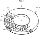
- the sensor 3 illustrated here is circular in shape with a central orifice 33 but it can take other shapes: rectangular, oblong, ellipsoidal with or without a central orifice.
- the central orifice 33 makes it possible to correctly position the sensor 3 in the cavity 21 of the housing which includes a central positioning stud (not shown).
- the sensor 3 therefore includes elements which make it possible to collect the liquid or to bring the signals detected by each microneedle to the box 2 for processing (not described here).
- Box 2 houses several elements for analyzing or extracting interstitial fluid.
- interstitial fluid For this purpose, please refer to the document WO 2019/141743 in the name of the applicant which describes in detail the measurement and detection of a physical quantity from microneedles in contact with a bodily fluid which may or may not be sampled.
- the watch may include a light indicator such as a diode, which may be used to signal the end of a sensor preparation operation.
- a light indicator such as a diode
- a microneedle is understood to mean a needle having a low height, preferably between 10 ⁇ m and 1000 ⁇ m, preferably between 0.3 mm and 0.8 mm.
- the height of the microneedles is low enough to avoid contact with a mechanical pain nerve of the wearer when the device is worn.
- Microneedles 5 are used to measure or collect body fluid.
- each needle 5 includes an internal cavity located at the rear of the tip, and the chemical or biochemical material capable of reacting with the analyte is located in this internal cavity.
- the senor 3 may comprise cavities located behind the needles 5, and/or inside the needles 5.
- one or more needles 5 may comprise an open channel.
- the cavities comprise the chemical or biochemical material capable of reacting with the analyte.
- the needles 5 are then capable of bringing the body fluid up to said cavities.
- Sensor 3 shown on the Figure 2 comprises, in addition to the needles 5, a substrate 311 provided with a plurality of metal tracks 312, a working conductivity electrode 313, a reference conductivity electrode 314.
- a voltage is generated between several needles. At least a portion of the needles 5 of the sensor 3 are at least partially immersed in the interstitial fluid. The chemical or biochemical material present on the surface of the needles 5 reacts with the glucose in the interstitial fluid.
- Sensor 3 thus provides an electrical current measurement, representative of the glucose concentration in the interstitial fluid.
- the central opening 33 is here circular in shape.
- the sensor 3 thus has, in this example, a generally annular shape.
- the senor 3 comprises a memory, configured among other things to record recalibration information.
- the recalibration information can then be recorded in the sensor 3 after transmission by a processing unit integrated into the watch 10, during a calibration process of the sensor 30.
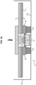
- FIGS. 3a , 3b illustrate an assembly comprising a capsule 10 and a pocket 40 according to a first embodiment presented according to a first position and a second position.
- the Figures 4a , 4b illustrate an assembly comprising a capsule 10 and a pocket 40 according to a second embodiment presented according to a first position and a second position.
- the capsule 10 comprises, in addition to the sensor 3, the patch 4 to which the sensor 3 is attached, the patch 4 covering at least in part the surface of the sensor 3.
- a part, for example a central part of the patch 4 defines an opening 12 in which the needles 5 of the sensor 3 are arranged.
- a surface of the sensor 5 is considered here to be the internal surface 31 of the sensor 5 which is directed towards the skin of the wearer.
- patch 4 can be above sensor 3.
- the opening 12 preferably has, in a diametrical direction, a minimum dimension, greater than or equal to 2 millimeters, preferably greater than or equal to 5 millimeters.
- the opening 12 therefore defines a free space in which the needles 5 are arranged.
- the opening 12 in which the needles are positioned therefore advantageously constitutes a cavity which makes it possible to protect the needles 5, in particular if they are to be handled with a view to installing the sensor 3 in the housing 2.
- the opening 12 is advantageously closed in its lower part by a rigid membrane 7a, 7b which can be pierced. We will come back to this.
- the lower part of the opening 12 is the one which is open.
- the membrane 7a, 7b makes it possible to close the open part of the opening 12 and therefore makes it possible to protect the needles 5 in the enclosure formed by the opening 12 and the membrane 7a, 7b.
- a membrane is understood to mean a rigid layer of material(s) which has a thin thickness greater than or equal to 0.05 mm and less than or equal to 0.50 mm.
- the rigid membrane 7a, 7b is formed from a layer of elastic or semi-elastic material.
- the membrane is made from a mesh of fine threads, an average thickness of the mesh preferably being greater than or equal to 0.05 millimeters and less than or equal to 0.50 mm.
- the membrane is made of rubber or artificial skin or metal or paper. Of course, other materials or combinations of materials are possible.
- At least one compressible spacer 9 having a first face 91 and a second face 92 opposite the first face 91 is attached to the patch 4 at the level of the opening 12.
- a pierceable pocket 40 is arranged at a distance from and opposite the needle(s) 5.
- the spacer 9 is configured to decompress once the thrust F is released, so that the needle 4 returns to a position at a distance from the pocket in the opening 12.
- the spacer 9 is therefore sized and configured in particular to come to bear on a first support element 212 opposite and to compress on this first support element 212.
- This first support element 212 acts as a counter-support for the spacer 9.
- the spacer 9 has an average thickness in the compressed or uncompressed position which is greater than or equal to 0.1 millimeters and is less than or equal to 2 millimeters.
- the thickness of the spacer 9 is chosen according to the height of the needles 5 and the thickness of the patch 4.
- the spacer 9 is made of an elastic or semi-elastic material and is for example a foam having elastic properties. It can also be for example rubber or a spring blade.
- the spacer 9 comprises at least a first spacer part 9a and a second spacer part 9b, the spacer 9 being formed of several parts.
- the first part 9a and the second part 9b are disjointed.
- the first part and the second part are in one piece.
- the spacer when the spacer is made up of disjointed parts, these may be 3, 4 or even more in number.
- the spacer surrounds the needles 5 at the level of the opening 12 as is visible on the Figures 3a , 3b , 4a , 4b .
- the thrust F required to pierce the pocket 40 is greater than or equal to 10 Newtons and less than or equal to 50 Newtons, preferably equal to 10 Newtons. Knowing that 10 Newtons corresponds to 1 kg of support, this corresponds to what an elderly person or a child can easily do. In other words, this covers a large number of users.
- the pocket 40 and spacer 9 assembly are therefore configured in this way.
- the patch 5 comprises different layers of adhesive 8 for fixing the sensor 3 to the outer layer 41 of the patch 4.
- Layers of adhesive also make it possible to fix the spacer 9 to a peelable film 11 and to fix the membrane 7a, 7b to the spacer 9 on its other face 92.
- the idea here is to be able to simply detach by removing the peelable film 11 from the outer layer 41 of the patch 4, the one that will remain after the installation of the sensor 3, the spacer 9 and the membrane 7a, 7b.
- peelable material is understood to mean a surface coating that can be detached dry and without breaking.
- a receptacle 21 houses the above elements and notably comprises a receiving surface 210 on which the support element 212 is arranged opposite the spacer 9 in order to facilitate its compression.
- a support element 212 takes the form of a boss projecting from the receiving surface 210 of the receptacle 21, the boss 212 being placed opposite the spacer 9. In the case where there are several spacers, as many bosses as there are spacers are provided.
- the receiving surface 210 is in the lower part 21a of the receptacle 21.
- An upper part 21b of the receptacle forms a cover and is removed to be able to position the capsule in the housing 2.
- the receptacle 21 comprises all the elements described above and constitutes a sterile storage enclosure for the capsule in order to prepare the sensor 3.
- the receptacle 21 is generally parallelepipedal in shape and takes the form of a box inside which the sensor 3, the patch 4 and the pocket 40 are placed.
- the receptacle 21 can be a charging dock, etc.
- the membrane 7a, 7b therefore protects the needles of the sensor 3 against contamination and vibrations while the sensor 3 is on the patch 4, and allows in combination with the preparation bag to calibrate or pre-wet the needles when the sensor is pushed towards the bag.
- the senor 3 is movable relative to the receptacle 21 between a first position in which the needle 5 is at a distance from and facing the membrane 7a, 7b and the pocket 40, the spacer 9 then being uncompressed, and a second position in which the membrane 7a, 7b and the pocket 40 are pierced by the needle 5 and in which the needle 5 is in contact with a volume of the preparation pocket 40, the spacer 9 then being compressed.
- the assembly comprises support means mounted on the receptacle 21, the support means being configured to move the sensor 2 relative to the receptacle 21 from the first position to the second position, the boss 212 acting as a counter-support for the spacer 9.
- the support means are the cover 21b of the receptacle 21 or the housing 2, the sensor 3 then being assembled to the housing 2.
- Bag 40 (or preparation bag) comprises a volume of a sensor preparation solution.
- the preparation solution is a calibration solution, having a volume concentration of a body analyte equal to a predetermined reference value.
- the bodily analyte to be analyzed is glucose
- the measurement provided by sensor 3 is representative of blood sugar
- the solution contained in the bag 40 here has a precisely known glucose concentration.
- This concentration is advantageously between 2 millimoles of glucose per liter and 20 millimoles of glucose per liter, more preferably between 6 millimoles of glucose per liter and 10 millimoles of glucose per liter.
- the preparation solution contained in the pocket 40 may be a pre-wetting solution, i.e. a solution that reproduces the chemical nature of the body fluid into which the sensor 3 is intended to be inserted (namely the interstitial fluid here).
- Pre-wetting consists of moistening a portion of the chemical or biochemical materials (such as active enzymatic elements) that enable the electrochemical measurement, contained for example on the upper layers of the needles 32. These chemical elements typically comprise active enzymatic elements.
- An advantage of performing pre-wetting of the sensor 3, during a preparation of the sensor 3, is to accelerate the convergence of subsequent measurements of the sensor in the body fluid.
- the sensor 3 thus quickly reaches an operational state.
- the preparation solution is produced here in the form of a gel.
- the preparation of the sensor 3 can also include a combination of pre-wetting and pre-calibration, the entire invention being able to allow both.
- the user takes hold of the capsule 10 which includes the sensor 3 and the patch 4 and also the membrane 7a.
- the capsule is therefore at this moment in the open air.
- the needles 5 are protected by the membrane 7a.
- the assembly according to this second embodiment includes all the elements of the first embodiment with the difference that the pocket 40 is here arranged on the membrane 7b.
- This membrane 7b is not intended to be pierced by the needles so that only the rigidity property is sought in order to support the pocket 40.
- pocket 40 can be pierced by needles 5.
- At least one second support element 213 is arranged below the pocket 40. As illustrated, on the Figure 4a , these are two bosses 213 projecting from the receiving surface 210. These second support elements serve to facilitate the piercing of the pocket 40 by the needles since in operation, the membrane and the pocket will come to bear on these support elements, the spacer 9 bearing as on the first support elements 212 as described previously.
- FIG. 4b illustrates the assembly according to the second embodiment with the pocket 40 pierced by the needles 5, the membrane 7 is positioned on the support elements below, and the spacer 9 is compressed on the first support elements 212.
- the calibration of the needles 5 can be carried out as described previously, the assembly returning to the position of the Figure 4a at the end of the operation.
Landscapes
- Health & Medical Sciences (AREA)
- Life Sciences & Earth Sciences (AREA)
- Physics & Mathematics (AREA)
- Heart & Thoracic Surgery (AREA)
- Molecular Biology (AREA)
- Pathology (AREA)
- Engineering & Computer Science (AREA)
- Biomedical Technology (AREA)
- Veterinary Medicine (AREA)
- Medical Informatics (AREA)
- Biophysics (AREA)
- Surgery (AREA)
- Animal Behavior & Ethology (AREA)
- General Health & Medical Sciences (AREA)
- Public Health (AREA)
- Optics & Photonics (AREA)
- Emergency Medicine (AREA)
- Measurement Of The Respiration, Hearing Ability, Form, And Blood Characteristics Of Living Organisms (AREA)
Claims (10)
- Anordnung, umfassend eine Kapsel (10) einer tragbaren Vorrichtung (1) zur Überwachung eines Körperanalyten, wobei die Kapsel (10) einen Sensor (3) umfasst, der ausgelegt ist, um eine Messung der Konzentration des Körperanalyten bereitzustellen, wobei der Sensor (3) eine Oberfläche (31) des Sensors (3) und mindestens eine an dem Sensor (3) an der Oberfläche (31) des Sensors (3) befestigte Nadel (5) umfasst,wobei die Kapsel (10) ferner ein den Sensor (3) tragendes Patch (4) umfasst, wobei das Patch (4) die Oberfläche (31) des Sensors (3) mindestens teilweise bedeckt, wobei ein Teil des Patchs (4) einen Durchbruch (12) definiert, in dem die Nadeln (5) des Sensors (3) angeordnet sind,wobei die Anordnung dadurch gekennzeichnet ist, dass sie umfasst:- mindestens einen ersten komprimierbaren Abstandshalter (9), der eine erste Fläche (91) gegenüber dem Patch (4) und eine zweite Fläche (92) gegenüber der ersten Fläche (91) aufweist,- einen Behälter (21), der eine Empfangsoberfläche (210) aufweist;- einen durchstechbaren Beutel (40), der auf der Empfangsoberfläche (210) beabstandet und gegenüber der Nadel (5) angeordnet ist, wobei die Anordnung derart ist, dass, wenn die Nadel (5) einen Schub (F) in Richtung des Beutels (40) erfährt, sie den Beutel (40) durchsticht, wobei der Abstandshalter (9) komprimiert wird, die Nadel (5) in Abwesenheit eines Schubs (F) gegenüber und beabstandet zum Beutel (40) zurückkehrt, wobei der Abstandshalter (9) dekomprimiert wird, wobei der Sensor (3) in Bezug auf den Behälter (21) zwischen einer ersten Position, in der sich die Nadel (5) in einem Abstand und gegenüber dem Beutel (40) befindet, wobei der Abstandshalter (9) dann nicht komprimiert ist, und einer zweiten Position, in der der Beutel (40) von der Nadel (5) durchstochen wird und in der die Nadel (5) mit einem Volumen des Beutels (40) in Kontakt ist, wobei der Abstandshalter (9) dann komprimiert ist, beweglich ist, wobei der Beutel (40) ein Volumen einer Zubereitungslösung des Sensors (3) umfasst.
- Anordnung nach Anspruch 1, umfassend eine feste Membran (7a, 7b), die an der zweiten Fläche (91) des Abstandshalters befestigt ist und sich beabstandet und gegenüber der Nadel (5) erstreckt, wobei die Membran (7a, 7b) ausgelegt ist, um den Durchbruch (12) zu verschließen, um die Nadel (5) zu schützen.
- Anordnung nach Anspruch 2, wobei die feste Membran (7a, 7b) aus einem elastischen oder halbelastischen Material besteht.
- Anordnung nach einem der vorhergehenden Ansprüche, wobei die Membran (7a) von der Nadel (5) durchstechbar ist, wobei der Beutel (40) unterhalb der Membran (7a) angeordnet ist, wobei die Anordnung ausgelegt ist, damit, wenn die Nadel (5) einen Schub (F) in Richtung der Membran (7a) erfährt, sie außer dem Beutel (40) die Membran (7a) durchstößt und vollständig in den Durchbruch (12) gegenüber und beabstandet von der Membran (7a) zurückkehrt, wenn kein Schub (F) vorhanden ist.
- Anordnung nach einem der Ansprüche 1 bis 3, wobei der Beutel (40) in dem Durchbruch (12) angeordnet ist und auf einer Oberfläche (7b1) der Membran (7b) aufliegt, die in den Durchbruch (12) mündet.
- Anordnung nach einem der Ansprüche 1 bis 5, wobei der Abstandshalter (9) in komprimierter oder nicht komprimierter Position eine Dicke von größer oder gleich 0,1 Millimeter und kleiner oder gleich 2 Millimeter aufweist.
- Anordnung nach einem der Ansprüche 1 bis 6, wobei der Abstandshalter (9) mindestens einen ersten Abstandshalterteil (9a) und einen zweiten Abstandshalterteil (9b) umfasst, der dem ersten Teil (9a) gegenüberliegt, wobei der erste Teil (9a) und der zweite Teil (9b) vorzugsweise unzusammenhängend sind.
- Anordnung nach einem der Ansprüche 1 bis 7 oder der Ansprüche 2 bis 7, wobei das Patch (4) eine abziehbare Folie (11) zwischen einer Klebeschicht (8) des Patchs (4) und dem Abstandshalter (9) umfasst, wobei die erste Fläche (91) des Abstandshalters (9) fest auf der abziehbaren Folie (11) klebt, wobei die abziehbare Folie (11) ausgelegt ist, um das Lösen der abziehbaren Folie (11), des Abstandshalters (9) und gegebenenfalls der Membran von einer Außenschicht (41) des Patchs (4) zu ermöglichen.
- Anordnung nach einem der Ansprüche 1 bis 8, umfassend mindestens ein erstes Stützelement (212), das sich gegenüber dem Abstandshalter (9) befindet, wobei das erste Stützelement ausgelegt ist, um das Komprimieren des Abstandshalters (9) und das Durchstechen des Beutels (40) mittels der Nadel (5) zu erleichtern.
- Anordnung nach einem der Ansprüche 1 bis 8, umfassend mindestens ein zweites Stützelement (210, 213), das sich gegenüber dem Beutel (40) befindet, wobei das zweite Stützelement ausgelegt ist, um das Durchstechen des Beutels (40) zu erleichtern.
Applications Claiming Priority (2)
| Application Number | Priority Date | Filing Date | Title |
|---|---|---|---|
| FR2109966A FR3127114A1 (fr) | 2021-09-22 | 2021-09-22 | Ensemble de préparation d’un capteur d’un dispositif de surveillance corporelle |
| PCT/FR2022/051784 WO2023047058A1 (fr) | 2021-09-22 | 2022-09-22 | Ensemble de préparation d'un capteur d'un dispositif de surveillance corporelle |
Publications (2)
| Publication Number | Publication Date |
|---|---|
| EP4404825A1 EP4404825A1 (de) | 2024-07-31 |
| EP4404825B1 true EP4404825B1 (de) | 2025-07-02 |
Family
ID=79831506
Family Applications (1)
| Application Number | Title | Priority Date | Filing Date |
|---|---|---|---|
| EP22792845.4A Active EP4404825B1 (de) | 2021-09-22 | 2022-09-22 | Anordnung zur vorbereitung eines sensors für eine körperüberwachungsvorrichtung |
Country Status (3)
| Country | Link |
|---|---|
| EP (1) | EP4404825B1 (de) |
| FR (1) | FR3127114A1 (de) |
| WO (1) | WO2023047058A1 (de) |
Families Citing this family (1)
| Publication number | Priority date | Publication date | Assignee | Title |
|---|---|---|---|---|
| FR3165725A1 (fr) * | 2024-08-23 | 2026-02-27 | Metyos | Kit de détection et/ou de mesure d’un analyte et/ou d’un paramètre physiologique dans un fluide biologique |
Family Cites Families (5)
| Publication number | Priority date | Publication date | Assignee | Title |
|---|---|---|---|---|
| US7524464B2 (en) * | 2003-09-26 | 2009-04-28 | Ahn Chong H | Smart disposable plastic lab-on-a-chip for point-of-care testing |
| US20090099427A1 (en) * | 2007-10-12 | 2009-04-16 | Arkal Medical, Inc. | Microneedle array with diverse needle configurations |
| FR3059886B1 (fr) | 2016-12-09 | 2021-04-09 | Pk Paris | Dispositif de surveillance corporelle |
| FR3076703B1 (fr) | 2018-01-16 | 2024-12-06 | Pk Paris | Systeme de surveillance corporelle avec adhesif |
| FR3084578B1 (fr) | 2018-08-03 | 2024-01-12 | Pkvitality | Gestion enfoncement de microaiguilles |
-
2021
- 2021-09-22 FR FR2109966A patent/FR3127114A1/fr active Pending
-
2022
- 2022-09-22 EP EP22792845.4A patent/EP4404825B1/de active Active
- 2022-09-22 WO PCT/FR2022/051784 patent/WO2023047058A1/fr not_active Ceased
Also Published As
| Publication number | Publication date |
|---|---|
| FR3127114A1 (fr) | 2023-03-24 |
| WO2023047058A1 (fr) | 2023-03-30 |
| EP4404825A1 (de) | 2024-07-31 |
Similar Documents
| Publication | Publication Date | Title |
|---|---|---|
| EP3829437B1 (de) | Mikronadeleindringungsmanagement | |
| FR3076703A1 (fr) | Systeme de surveillance corporelle avec adhesif | |
| EP3829438B1 (de) | Beidseitig steifes klebepflaster | |
| EP3829436B1 (de) | Multipositionskapsel | |
| WO2018104647A1 (fr) | Dispositif de surveillance corporelle | |
| EP3772331A1 (de) | Körperüberwachungssystem mit einer mikronadel | |
| WO2021209727A1 (fr) | Préparation d'un capteur à aiguille d'un système de surveillance corporelle | |
| EP3740118B1 (de) | System zur körperüberwachung durch elektrophorese | |
| WO2020025818A1 (fr) | Ratio métal/surface de microaiguille | |
| WO2023047058A1 (fr) | Ensemble de préparation d'un capteur d'un dispositif de surveillance corporelle | |
| EP4009864B1 (de) | Körperüberwachungssystem mit einer mikronadel | |
| EP4132357A1 (de) | Analytmessvorrichtung mit einem klebepflaster | |
| EP4186421B1 (de) | Verfahren zur herstellung eines elementaren moduls eines mikronadelsensors | |
| EP4099902B1 (de) | Gerät mit heftpflaster zur messung eines analyts | |
| FR3138320A1 (fr) | Procédé de fabrication d’une micro-aiguille et en particulier métallisation de la pointe d’une microaiguille | |
| EP4395642A1 (de) | Körperüberwachungsvorrichtung mit verbesserten kontakten | |
| WO2022214770A1 (fr) | Dispositif de surveillance corporelle comprenant des contacts électriques améliorés | |
| WO2021009376A1 (fr) | Systeme de surveillance corporelle avec adhesif | |
| FR3120779A1 (fr) | Capteur pour dispositif de surveillance corporelle limitant les irritations | |
| FR3098702A1 (fr) | Systeme de surveillance corporelle avec adhesif | |
| FR3138998A1 (fr) | Correction de la mesure d’une concentration d’un analyte | |
| FR3132835A1 (fr) | Capteur à microaiguilles comprenant une base, au moins un module élémentaire de support de microaiguille |
Legal Events
| Date | Code | Title | Description |
|---|---|---|---|
| STAA | Information on the status of an ep patent application or granted ep patent |
Free format text: STATUS: UNKNOWN |
|
| STAA | Information on the status of an ep patent application or granted ep patent |
Free format text: STATUS: THE INTERNATIONAL PUBLICATION HAS BEEN MADE |
|
| PUAI | Public reference made under article 153(3) epc to a published international application that has entered the european phase |
Free format text: ORIGINAL CODE: 0009012 |
|
| STAA | Information on the status of an ep patent application or granted ep patent |
Free format text: STATUS: REQUEST FOR EXAMINATION WAS MADE |
|
| 17P | Request for examination filed |
Effective date: 20240327 |
|
| AK | Designated contracting states |
Kind code of ref document: A1 Designated state(s): AL AT BE BG CH CY CZ DE DK EE ES FI FR GB GR HR HU IE IS IT LI LT LU LV MC MK MT NL NO PL PT RO RS SE SI SK SM TR |
|
| DAV | Request for validation of the european patent (deleted) | ||
| DAX | Request for extension of the european patent (deleted) | ||
| GRAP | Despatch of communication of intention to grant a patent |
Free format text: ORIGINAL CODE: EPIDOSNIGR1 |
|
| STAA | Information on the status of an ep patent application or granted ep patent |
Free format text: STATUS: GRANT OF PATENT IS INTENDED |
|
| INTG | Intention to grant announced |
Effective date: 20250213 |
|
| RIN1 | Information on inventor provided before grant (corrected) |
Inventor name: PIERART, LUC |
|
| GRAS | Grant fee paid |
Free format text: ORIGINAL CODE: EPIDOSNIGR3 |
|
| GRAA | (expected) grant |
Free format text: ORIGINAL CODE: 0009210 |
|
| STAA | Information on the status of an ep patent application or granted ep patent |
Free format text: STATUS: THE PATENT HAS BEEN GRANTED |
|
| AK | Designated contracting states |
Kind code of ref document: B1 Designated state(s): AL AT BE BG CH CY CZ DE DK EE ES FI FR GB GR HR HU IE IS IT LI LT LU LV MC MK MT NL NO PL PT RO RS SE SI SK SM TR |
|
| REG | Reference to a national code |
Ref country code: GB Ref legal event code: FG4D Free format text: NOT ENGLISH |
|
| REG | Reference to a national code |
Ref country code: CH Ref legal event code: EP |
|
| REG | Reference to a national code |
Ref country code: DE Ref legal event code: R096 Ref document number: 602022017041 Country of ref document: DE |
|
| REG | Reference to a national code |
Ref country code: IE Ref legal event code: FG4D Free format text: LANGUAGE OF EP DOCUMENT: FRENCH |
|
| REG | Reference to a national code |
Ref country code: CH Ref legal event code: U11 Free format text: ST27 STATUS EVENT CODE: U-0-0-U10-U11 (AS PROVIDED BY THE NATIONAL OFFICE) Effective date: 20251001 |
|
| PGFP | Annual fee paid to national office [announced via postgrant information from national office to epo] |
Ref country code: DE Payment date: 20250916 Year of fee payment: 4 |
|
| PGFP | Annual fee paid to national office [announced via postgrant information from national office to epo] |
Ref country code: FR Payment date: 20250812 Year of fee payment: 4 Ref country code: AT Payment date: 20251020 Year of fee payment: 4 |
|
| REG | Reference to a national code |
Ref country code: CH Ref legal event code: R17 Free format text: ST27 STATUS EVENT CODE: U-0-0-R10-R17 (AS PROVIDED BY THE NATIONAL OFFICE) Effective date: 20251024 |
|
| REG | Reference to a national code |
Ref country code: NL Ref legal event code: MP Effective date: 20250702 |
|
| RAP4 | Party data changed (patent owner data changed or rights of a patent transferred) |
Owner name: WIZP AS |
|
| PG25 | Lapsed in a contracting state [announced via postgrant information from national office to epo] |
Ref country code: PT Free format text: LAPSE BECAUSE OF FAILURE TO SUBMIT A TRANSLATION OF THE DESCRIPTION OR TO PAY THE FEE WITHIN THE PRESCRIBED TIME-LIMIT Effective date: 20251103 |
|
| PG25 | Lapsed in a contracting state [announced via postgrant information from national office to epo] |
Ref country code: NL Free format text: LAPSE BECAUSE OF FAILURE TO SUBMIT A TRANSLATION OF THE DESCRIPTION OR TO PAY THE FEE WITHIN THE PRESCRIBED TIME-LIMIT Effective date: 20250702 |
|
| REG | Reference to a national code |
Ref country code: AT Ref legal event code: MK05 Ref document number: 1808281 Country of ref document: AT Kind code of ref document: T Effective date: 20250702 |
|
| PG25 | Lapsed in a contracting state [announced via postgrant information from national office to epo] |
Ref country code: IS Free format text: LAPSE BECAUSE OF FAILURE TO SUBMIT A TRANSLATION OF THE DESCRIPTION OR TO PAY THE FEE WITHIN THE PRESCRIBED TIME-LIMIT Effective date: 20251102 |
|
| PG25 | Lapsed in a contracting state [announced via postgrant information from national office to epo] |
Ref country code: NO Free format text: LAPSE BECAUSE OF FAILURE TO SUBMIT A TRANSLATION OF THE DESCRIPTION OR TO PAY THE FEE WITHIN THE PRESCRIBED TIME-LIMIT Effective date: 20251002 |
|
| REG | Reference to a national code |
Ref country code: LT Ref legal event code: MG9D |
|
| PG25 | Lapsed in a contracting state [announced via postgrant information from national office to epo] |
Ref country code: AT Free format text: LAPSE BECAUSE OF FAILURE TO SUBMIT A TRANSLATION OF THE DESCRIPTION OR TO PAY THE FEE WITHIN THE PRESCRIBED TIME-LIMIT Effective date: 20250702 |
|
| PG25 | Lapsed in a contracting state [announced via postgrant information from national office to epo] |
Ref country code: FI Free format text: LAPSE BECAUSE OF FAILURE TO SUBMIT A TRANSLATION OF THE DESCRIPTION OR TO PAY THE FEE WITHIN THE PRESCRIBED TIME-LIMIT Effective date: 20250702 |
|
| PG25 | Lapsed in a contracting state [announced via postgrant information from national office to epo] |
Ref country code: HR Free format text: LAPSE BECAUSE OF FAILURE TO SUBMIT A TRANSLATION OF THE DESCRIPTION OR TO PAY THE FEE WITHIN THE PRESCRIBED TIME-LIMIT Effective date: 20250702 |
|
| PG25 | Lapsed in a contracting state [announced via postgrant information from national office to epo] |
Ref country code: GR Free format text: LAPSE BECAUSE OF FAILURE TO SUBMIT A TRANSLATION OF THE DESCRIPTION OR TO PAY THE FEE WITHIN THE PRESCRIBED TIME-LIMIT Effective date: 20251003 |
|
| PGFP | Annual fee paid to national office [announced via postgrant information from national office to epo] |
Ref country code: CH Payment date: 20251001 Year of fee payment: 4 |
|
| PG25 | Lapsed in a contracting state [announced via postgrant information from national office to epo] |
Ref country code: SE Free format text: LAPSE BECAUSE OF FAILURE TO SUBMIT A TRANSLATION OF THE DESCRIPTION OR TO PAY THE FEE WITHIN THE PRESCRIBED TIME-LIMIT Effective date: 20250702 Ref country code: CZ Free format text: LAPSE BECAUSE OF FAILURE TO SUBMIT A TRANSLATION OF THE DESCRIPTION OR TO PAY THE FEE WITHIN THE PRESCRIBED TIME-LIMIT Effective date: 20250702 |
|
| PG25 | Lapsed in a contracting state [announced via postgrant information from national office to epo] |
Ref country code: LV Free format text: LAPSE BECAUSE OF FAILURE TO SUBMIT A TRANSLATION OF THE DESCRIPTION OR TO PAY THE FEE WITHIN THE PRESCRIBED TIME-LIMIT Effective date: 20250702 |
|
| PG25 | Lapsed in a contracting state [announced via postgrant information from national office to epo] |
Ref country code: PL Free format text: LAPSE BECAUSE OF FAILURE TO SUBMIT A TRANSLATION OF THE DESCRIPTION OR TO PAY THE FEE WITHIN THE PRESCRIBED TIME-LIMIT Effective date: 20250702 Ref country code: BG Free format text: LAPSE BECAUSE OF FAILURE TO SUBMIT A TRANSLATION OF THE DESCRIPTION OR TO PAY THE FEE WITHIN THE PRESCRIBED TIME-LIMIT Effective date: 20250702 |
|
| PG25 | Lapsed in a contracting state [announced via postgrant information from national office to epo] |
Ref country code: RS Free format text: LAPSE BECAUSE OF FAILURE TO SUBMIT A TRANSLATION OF THE DESCRIPTION OR TO PAY THE FEE WITHIN THE PRESCRIBED TIME-LIMIT Effective date: 20251002 |
|
| PG25 | Lapsed in a contracting state [announced via postgrant information from national office to epo] |
Ref country code: ES Free format text: LAPSE BECAUSE OF FAILURE TO SUBMIT A TRANSLATION OF THE DESCRIPTION OR TO PAY THE FEE WITHIN THE PRESCRIBED TIME-LIMIT Effective date: 20250702 |
|
| PG25 | Lapsed in a contracting state [announced via postgrant information from national office to epo] |
Ref country code: RO Free format text: LAPSE BECAUSE OF FAILURE TO SUBMIT A TRANSLATION OF THE DESCRIPTION OR TO PAY THE FEE WITHIN THE PRESCRIBED TIME-LIMIT Effective date: 20250702 |
|
| PG25 | Lapsed in a contracting state [announced via postgrant information from national office to epo] |
Ref country code: SM Free format text: LAPSE BECAUSE OF FAILURE TO SUBMIT A TRANSLATION OF THE DESCRIPTION OR TO PAY THE FEE WITHIN THE PRESCRIBED TIME-LIMIT Effective date: 20250702 |
|
| PG25 | Lapsed in a contracting state [announced via postgrant information from national office to epo] |
Ref country code: DK Free format text: LAPSE BECAUSE OF FAILURE TO SUBMIT A TRANSLATION OF THE DESCRIPTION OR TO PAY THE FEE WITHIN THE PRESCRIBED TIME-LIMIT Effective date: 20250702 |
|
| PG25 | Lapsed in a contracting state [announced via postgrant information from national office to epo] |
Ref country code: IT Free format text: LAPSE BECAUSE OF FAILURE TO SUBMIT A TRANSLATION OF THE DESCRIPTION OR TO PAY THE FEE WITHIN THE PRESCRIBED TIME-LIMIT Effective date: 20250702 |
|
| REG | Reference to a national code |
Ref country code: CH Ref legal event code: R17 Free format text: ST27 STATUS EVENT CODE: U-0-0-R10-R17 (AS PROVIDED BY THE NATIONAL OFFICE) Effective date: 20260417 |
|
| PG25 | Lapsed in a contracting state [announced via postgrant information from national office to epo] |
Ref country code: SK Free format text: LAPSE BECAUSE OF FAILURE TO SUBMIT A TRANSLATION OF THE DESCRIPTION OR TO PAY THE FEE WITHIN THE PRESCRIBED TIME-LIMIT Effective date: 20250702 Ref country code: EE Free format text: LAPSE BECAUSE OF FAILURE TO SUBMIT A TRANSLATION OF THE DESCRIPTION OR TO PAY THE FEE WITHIN THE PRESCRIBED TIME-LIMIT Effective date: 20250702 |
|
| PLBE | No opposition filed within time limit |
Free format text: ORIGINAL CODE: 0009261 |
|
| STAA | Information on the status of an ep patent application or granted ep patent |
Free format text: STATUS: NO OPPOSITION FILED WITHIN TIME LIMIT |