EP4404440A2 - Générateur électromagnétique de balourd pour dispositif de compactage de sol - Google Patents
Générateur électromagnétique de balourd pour dispositif de compactage de sol Download PDFInfo
- Publication number
- EP4404440A2 EP4404440A2 EP24180789.0A EP24180789A EP4404440A2 EP 4404440 A2 EP4404440 A2 EP 4404440A2 EP 24180789 A EP24180789 A EP 24180789A EP 4404440 A2 EP4404440 A2 EP 4404440A2
- Authority
- EP
- European Patent Office
- Prior art keywords
- rotor
- mass
- soil compaction
- compaction device
- unbalance
- Prior art date
- Legal status (The legal status is an assumption and is not a legal conclusion. Google has not performed a legal analysis and makes no representation as to the accuracy of the status listed.)
- Pending
Links
Images


Classifications
-
- E—FIXED CONSTRUCTIONS
- E01—CONSTRUCTION OF ROADS, RAILWAYS, OR BRIDGES
- E01C—CONSTRUCTION OF, OR SURFACES FOR, ROADS, SPORTS GROUNDS, OR THE LIKE; MACHINES OR AUXILIARY TOOLS FOR CONSTRUCTION OR REPAIR
- E01C19/00—Machines, tools or auxiliary devices for preparing or distributing paving materials, for working the placed materials, or for forming, consolidating, or finishing the paving
- E01C19/22—Machines, tools or auxiliary devices for preparing or distributing paving materials, for working the placed materials, or for forming, consolidating, or finishing the paving for consolidating or finishing laid-down unset materials
- E01C19/23—Rollers therefor; Such rollers usable also for compacting soil
- E01C19/28—Vibrated rollers or rollers subjected to impacts, e.g. hammering blows
- E01C19/286—Vibration or impact-imparting means; Arrangement, mounting or adjustment thereof; Construction or mounting of the rolling elements, transmission or drive thereto, e.g. to vibrator mounted inside the roll
-
- E—FIXED CONSTRUCTIONS
- E01—CONSTRUCTION OF ROADS, RAILWAYS, OR BRIDGES
- E01C—CONSTRUCTION OF, OR SURFACES FOR, ROADS, SPORTS GROUNDS, OR THE LIKE; MACHINES OR AUXILIARY TOOLS FOR CONSTRUCTION OR REPAIR
- E01C19/00—Machines, tools or auxiliary devices for preparing or distributing paving materials, for working the placed materials, or for forming, consolidating, or finishing the paving
- E01C19/22—Machines, tools or auxiliary devices for preparing or distributing paving materials, for working the placed materials, or for forming, consolidating, or finishing the paving for consolidating or finishing laid-down unset materials
- E01C19/30—Tamping or vibrating apparatus other than rollers ; Devices for ramming individual paving elements
- E01C19/34—Power-driven rammers or tampers, e.g. air-hammer impacted shoes for ramming stone-sett paving; Hand-actuated ramming or tamping machines, e.g. tampers with manually hoisted dropping weight
- E01C19/38—Power-driven rammers or tampers, e.g. air-hammer impacted shoes for ramming stone-sett paving; Hand-actuated ramming or tamping machines, e.g. tampers with manually hoisted dropping weight with means specifically for generating vibrations, e.g. vibrating plate compactors, immersion vibrators
-
- H—ELECTRICITY
- H02—GENERATION; CONVERSION OR DISTRIBUTION OF ELECTRIC POWER
- H02K—DYNAMO-ELECTRIC MACHINES
- H02K7/00—Arrangements for handling mechanical energy structurally associated with dynamo-electric machines, e.g. structural association with mechanical driving motors or auxiliary dynamo-electric machines
- H02K7/06—Means for converting reciprocating motion into rotary motion or vice versa
- H02K7/061—Means for converting reciprocating motion into rotary motion or vice versa using rotary unbalanced masses
- H02K7/063—Means for converting reciprocating motion into rotary motion or vice versa using rotary unbalanced masses integrally combined with motor parts, e.g. motors with eccentric rotors
Definitions
- the invention relates to a soil compaction device with an unbalance exciter.
- Such soil compaction devices are often also referred to as vibrating plates or vibrating plates. They usually have an upper mass and a lower mass that can be moved relative to the upper mass. Such vibrating plates are usually driven by an internal combustion engine, which is then added to the upper mass. A ground contact plate is provided on the lower mass, with which the soil underneath can be compacted.
- the ground contact plate is subjected to an unbalance force and thus a vibration by an unbalance exciter in order to achieve the desired soil compaction.
- the unbalance exciter and the ground contact plate are thus counted as the sub-mass.
- a vibration decoupling device for example a spring device with the aid of rubber buffers, is provided between the upper mass and the lower mass so that the strong vibrations generated on the lower mass are transmitted to the upper side only to the smallest possible extent.
- the unbalance exciter often has one or more unbalance shafts that carry an unbalance mass in order to achieve the desired vibration effect when the unbalance shafts or unbalance masses rotate.
- the drive energy of the drive motor is transmitted in a suitable manner.
- a belt drive can be provided between the combustion engine on the top and the unbalance exciter on the bottom mass.
- a hydraulic system is often used to transmit the drive energy.
- Fig.1 shows an example of a vibrating plate known from the prior art serving as a soil compaction device.
- the vibration plate has an upper mass 1 and a lower mass 2 that is movable relative to the upper mass 1.
- the lower mass 2 is coupled to the upper mass 1 via rubber buffers 3 that serve as a vibration decoupling device.
- the upper mass 1 has a support frame 4 on which, in the example shown, an internal combustion engine 5 is held, which is also assigned to the upper mass 1.
- the internal combustion engine 5 is enclosed by a protective frame 6.
- the base mass 2 has a ground contact plate 7, with the help of which the soil underneath can be compacted.
- a vibration exciter or unbalance exciter 8 which also belongs to the base mass 2, is arranged on the upper side of the ground contact plate.
- the unbalance exciter 8 has at least one, but often also two or more unbalance shafts, which are driven in rotation by the combustion engine 5. Due to the unbalance masses carried by the unbalance shafts, strong centrifugal forces arise, which lead to corresponding vibrations of the ground contact plate 7 and thus of the entire base mass 2. These vibrations are desired and serve to effectively compact the soil.
- a V-belt drive is generally provided between the combustion engine 5 and the unbalance exciter 8 and thus between the upper mass 1 and the lower mass 2.
- the combustion engine 5 drives a hydraulic pump so that a hydraulic fluid can be placed under high pressure.
- a hydraulic motor is then provided on the unbalance exciter 8, which is operated with the hydraulic pressure in order to set the unbalance shafts in the unbalance exciter 8 in rotation.
- a guide drawbar 9 is also attached to the upper mass 2 or the support frame 4.
- a throttle lever 10 is provided on the guide drawbar 9 to influence the engine speed of the combustion engine.
- a control handle 11 is arranged at the upper end of the guide drawbar 9, via which the relative rotational position of the unbalance shafts in the unbalance exciter 8, in particular their phase position to one another, can be adjusted in a known manner. In this way, forward and backward travel of the vibration plate can be achieved in a known manner.
- Vibration plates are also known in the prior art in which the electric motor is mounted directly on the base mass 2, namely in particular on the ground contact plate 7 near the unbalance exciter 8, in order to drive the one or more unbalance shafts in the unbalance exciter 8.
- the electric motor If the electric motor is installed on the base of the vibrating plate, the electric motor and the unbalance exciter (vibration exciter) perform different tasks.
- the electric motor generates the torque to drive the unbalances, while the rotating unbalances of the unbalance exciter generate the forces required to move the vibrating plate.
- the invention is based on the object of specifying a soil compaction device driven by an electric motor, which has a simplified and more compact design compared to the prior art.
- An unbalance exciter for a soil compaction device comprising an electric motor which has a rotor and a stator which at least partially encloses the rotor, wherein the rotor has an unbalance mass which can be moved at least partially past an inner side of the stator during rotation of the rotor.
- the rotor is therefore not only designed as a component of the electric motor, but also serves as an unbalanced shaft that carries the unbalanced mass in order to generate the desired vibration forces when the motor is operating.
- the rotor can thus serve as the drive shaft of the electric motor and as an unbalanced mass at the same time. Accordingly, the rotor can also be referred to as an "unbalanced rotor".
- the stator can be designed as a magnetic exciter of the rotor.
- an unbalance exciter is specified that has a particularly compact design, since the drive motor and unbalance exciter components are no longer provided separately from one another, but are formed as a single unit.
- the unbalanced mass can be moved at least partially past the inside of the stator when the rotor rotates. This means that at least part of the unbalanced mass is not axially offset from the stator, but rather is axially at the same height as the stator. This part of the unbalanced mass belonging to the rotor thus moves through the space enclosed by the stator.
- a further part of the unbalanced mass can also be arranged axially offset from the stator, i.e. outside the space enclosed by the stator.
- a significant part of the unbalanced mass is integrated into the electric motor, i.e. enclosed by the stator.
- the rotor can have an additional mass as an unbalanced mass over part of its circumference, to which no counter mass is provided opposite the axis of rotation of the rotor to compensate for the unbalanced mass.
- the principle of the unbalanced mass is that it creates a mass imbalance for the rotor. Only then can the desired unbalance be achieved when the rotor rotates, which is necessary to generate the vibrations.
- the additional mass on the rotor that causes the unbalance mass can be at least 5% of the total mass of the rotor. Only if this additional mass is significant, i.e. at least 5% of the total mass of the rotor, can the desired unbalance force and thus vibration effect be achieved during operation. In variants, even larger unbalance masses can be used as a basis, for example at least 10% or at least 15% of the total mass of the rotor.
- the rotor can have several rotor poles distributed around the circumference, whereby the stator can have several stator poles distributed over a circular arc in order to Interaction with the rotor poles to realize an electromotive function. It is not necessary at this point to go into the details of the construction of electric motors that are known per se and suitable for the present application (for example reluctance motors, in particular switched reluctance motors, synchronous motors, asynchronous motors) in detail, since they are widely known.
- control devices may be required to implement the electromotor function.
- the unbalanced mass can be designed as a mass that extends over part of the circumference of the rotor, with at least one rotor pole also being formed in the circumferential region of the rotor in which the unbalanced mass is provided. This means that the unbalanced mass has the rotor poles necessary to achieve the electromotive function on the circumference.
- mass elements can be provided on or between some of these rotor poles in order to form the unbalanced mass on the rotor in this way.
- At least one rotor pole can also be formed in the peripheral area of the rotor in which no unbalanced mass is provided.
- the structure of the rotor corresponds to a "classic" rotor, which does not carry any additional unbalanced mass in this area.
- the rotor can be made in one piece from a soft magnetic material.
- This soft magnetic material can in particular be iron, which also advantageously has a high density in order to cause a strong vibration effect through the unbalanced mass when the rotor is operating.
- the rotor can also be assembled from different components, so that the "poles" and "unbalanced mass” components can be made from different materials.
- the unbalanced masses can be designed in the form of steel bodies, for example, which are attached in a suitable manner, for example by screw connections, to the actual rotor, which has the poles.
- a steel body can also have the unbalanced masses as a base, with the poles made of soft magnetic material being attached in a suitable manner to the steel body and supported by it.
- the poles can also be made from an electrical sheet, for example.
- the stator can be cylindrical, i.e. completely surround the rotor on the circumference.
- the stator is then basically designed in the form of a hollow cylinder.
- the stator can only surround the rotor via a circular segment on the circumference.
- the stator is designed as a partial stator, for example as a hollow cylinder segment. In cross-section, the stator then basically has the shape of a circular segment.
- the stator can extend over a suitable angle on the circumference of the rotor, for example over an angle of up to 180°. An angle range of 90 to 270° is also possible.
- stator For the electric motor to operate, it is therefore not absolutely necessary for the stator to completely enclose the rotor around its circumference. It may be sufficient for the electromagnetic fields generated by the stator to be generated only over a partial circumference.
- the stator poles can be distributed over the inner circumference of the stator.
- the electric motor is designed as a reluctance motor.
- the reluctance motor has proven to be particularly advantageous due to its principle.
- the torque in the rotor is generated exclusively by the reluctance force, so that the motor is neither equipped with permanent magnets nor has electrical windings.
- This principle also eliminates any kind of wear-prone slip rings and brushes.
- the rotor has distinct poles and is made of a highly permeable, soft magnetic material such as electrical steel.
- the reluctance motor has a low torque density compared to permanent magnet excited machines such as the synchronous motor is not a problem for the application in an unbalance exciter. There, the unbalanced mass only has to be brought to the desired speed and kept there. After the unbalance exciter has started up, the nominal torque of the reluctance motor is sufficient to maintain the speed.
- a frequency converter is usually used to control the reluctance motor, which also enables the motor to be started directly.
- the described unbalance exciter can be used particularly advantageously in a soil compaction device.
- the soil compaction device has an upper mass and a lower mass that can be moved relative to the upper mass and has a ground contact plate for soil compaction.
- a vibration decoupling device can be arranged between the upper mass and the lower mass in order to prevent the vibrations of the lower mass from being transmitted to the upper mass or to only transmit them to a small extent.
- An unbalance exciter in the manner described above is arranged on the lower mass in order to apply an unbalance force to the ground contact plate.
- Such a soil compaction device can in particular be a vibrating plate or a vibrating plate with which soil can be effectively compacted or stones can be vibrated into the soil.
- the soil compaction device can be designed as a hand-held soil compaction device, in which case a guide device, for example a drawbar, is preferably attached to the top, via which the operator can guide the soil compaction device.
- a guide device for example a drawbar
- the soil compaction device can also be remotely controlled, in which case no guide drawbar is required.
- the unbalance or vibration forces generated by the unbalance exciter can be used to achieve a driving movement (forwards, backwards) and also a steering movement (left turn, right turn) of the soil compaction device.
- the base mass can have at least two unbalance exciters, which can be controlled independently of one another by a control device. It is also possible for an unbalance exciter to contain several electric motors with rotors and unbalance masses assigned to them, the rotation of which can each be controlled individually. In this way, it is possible for each of the unbalance exciters or each of the unbalance rotors to generate a different unbalance force in order to steer the soil compaction device.
- control device can be designed to enable electrical control of the electric motors in the unbalance exciters.
- control device can be used to bring about different rotational positions of the respective rotors in the unbalance exciters.
- the rotational position is understood to be the respective angular position of the unbalanced mass assigned to a rotor, i.e. in particular the center of gravity of the unbalanced mass.
- the unbalance exciter can be arranged on the top of the ground contact plate. This enables a particularly effective introduction of the vibrations generated by the unbalance exciter into the ground contact plate in order to achieve effective soil compaction.
- the ground contact plate can have a recess on its upper side, wherein the rotor of the unbalance exciter can be positioned on the ground contact plate in such a way that it protrudes at least partially into the recess.
- a recess can also be understood as a gap between two or more reinforcing ribs.
- Such ribs are often provided on the top of ground contact plates, whereby the ground contact plates are usually manufactured as cast parts or welded constructions.
- the unbalance exciter can be arranged on the top of the ground contact plate in such a way that part of the rotor (the lower part of the horizontally positioned rotor) can protrude into the corresponding recess or the space between the reinforcing ribs. In this way, the rotor can be at least partially sunk into the ground contact plate so that the overall height can be significantly reduced. The rotor is moved as close as possible to the underside of the ground contact plate.
- a wall thickness between a bottom of the recess and a bottom of the ground contact plate can be in a range of 10 mm to 30 mm, e.g. approx. 20 mm. This makes it possible to position the rotor very low and keep the overall height low.
- the distance between the surface of a virtual cylinder that surrounds the rotor and the underside of the ground contact plate can be in a range of 10 mm to 80 mm, e.g. between 30 mm and 40 mm, e.g. around 35 mm.
- the virtual cylinder thus surrounds the rotor or the space used by the rotor during rotation.
- the distance between the surface of this virtual cylinder should be as small as possible in order to keep the installation height low and to effectively introduce the vibrations into the ground contact plate.
- the ground contact plate can form part of a housing of the unbalance exciter.
- the ground contact plate can form the lower part of the housing, while an upper part of the housing can be attached to the top of the ground contact plate in the manner of a cover. Accordingly, no separate housing component is required on the underside of the exciter, so that construction effort, material and manufacturing costs can be saved.
- ground contact plate itself can be part of the housing of the unbalance exciter (here in particular the lower part of the housing), it is also possible to move the position of the rotor as downwards as possible.
- a vibration plate according to the invention thus differs from the one in Fig.1
- the vibration plate shown is characterized primarily by the fact that an electric motor drive is provided and that the electric motor drive and the unbalance exciter comprise an integrated, common structural unit.
- Fig.2 shows a basic schematic cross-section through an unbalance exciter 20 according to the invention, which is also designed as an electric motor.
- the unbalance exciter 20 has a rotor 21 and a stator 22.
- the stator 22 does not completely enclose the rotor 21 in a sleeve-like manner over 360° on the circumference. Rather, the stator 22 is designed as a partial stator in the form of a semi-cylindrical sleeve and only extends over an angle of 180°.
- stator poles 23 (in the example shown, a total of eight rotor poles) are formed on the circumference of the rotor 21.
- stator poles 24 (in the example shown, a total of six stator poles) are distributed on the (half) circumference of the stator.
- the stator poles 24 are in Fig.2 numbered 1 to 6.
- the spaces between the rotor poles 23 in the lower area are filled by additional masses 25 that are integrally connected to the rotor poles 23 (in the example shown, a total of four masses 25), which together form an unbalanced mass.
- additional masses 25 that are integrally connected to the rotor poles 23 (in the example shown, a total of four masses 25), which together form an unbalanced mass.
- no counter masses are assigned to these mass elements 25, such as Fig.2
- the rotor 21 in the upper half of the picture Fig.2 the spaces between the rotor poles 23 are left free.
- the rotor 21 Accordingly, due to the asymmetrical mass distribution during rotation, the rotor 21 generates a considerable unbalance force, which can advantageously be introduced directly into the ground contact plate 7 of the vibration plate and serve to compact the soil.
- the imbalance exciter 20 shown and the electric motor implemented by it are advantageously designed as a reluctance motor.
- the electric motor can be designed as a switched reluctance motor.
- the stator poles 24 are switched through one after the other, namely in the pole combinations 4-1, 5-2, 6-3.
- a control device (not shown) is provided, which can have, among other things, a frequency converter.
- the rotor 21 is thus designed both as the drive shaft of the motor and as the unbalance shaft.
- the stator 22 serves as the magnetic exciter of the rotor 21. In this way, a very compact design of the unbalance exciter 20 is possible, in which costs, weight and construction volume can be kept within defined limits.
- the electric motor implemented by the unbalance exciter 20 can use the physical properties of a reluctance motor, in which the rotor torque is generated by the reluctance force.
- the active part of the machine is not equipped with magnets, nor are there any electrical windings, short-circuit bars or similar on the rotor 21, as would be usual with induction motors. There are also no slip rings and brushes that are susceptible to wear.
- the pronounced rotor poles 23 of the rotor 21 can consist of a soft magnetic material with high permeability, as is also used in electric motors.
- the rotor 21 can be made entirely in one piece from the soft magnetic material.
- the rotor 21 can also be assembled from several components.
- the commutation of the rotor 21 takes place via the electrically excited stator poles 24, which interact with the rotor poles 23.
- the operating principle in this case is that of a synchronous machine with a frequency converter individually assigned to the unbalance.
- stator 22 makes it possible to assemble the stator 22 from partial segments, whereby - as already explained - it is not necessary to design the stator 22 as a cylinder, as is the case with classic electric motors.
- the only decisive factor for the function of the machine is that a rotation of the rotor 21 can be generated by switching the stator coils (stator poles 24).
- the rotor position by arranging and/or controlling the magnetically active poles 23, 24 of the stator 22 and rotor 21. If several unbalance rotors are provided in the unbalance exciter 20, the positions of the various unbalance rotors (rotors 21) can be adjusted relative to one another, which allows the vibration plate to be controlled in its direction of movement without additional components (such as a hydraulic or mechanical unbalance adjustment).
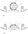
- Fig.3 shows an example of a soil compaction device with a ground contact plate 7 and an unbalance exciter 20 mounted on it.
- the unbalance exciter 20 has the rotor 21, which is rotatably mounted in the stator 22.
- the stator 22 is accommodated in an exciter housing 12, which is fastened to the top of the ground contact plate 7.
- the distance between the axis of rotation of the rotor 21 and the underside of the ground contact plate 7 is relatively large.
- Fig.4 shows a variant in which this distance is significantly smaller.
- stator 22 is only half-shell-shaped, so that it surrounds the rotor 21 only over a circular segment on the circumference, similar to Fig.2
- the stator 22 extends over an angle of approximately 180 degrees.
- a recess 13 is also provided, into which the rotor 21 projects. In this way, the rotor 21 can be brought very close to the underside of the ground contact plate 7, which is effective for compaction.
- Fig.5 in a schematic detail enlargement of Fig.4 that the rotor 21 can be surrounded on its outer circumference by an imaginary virtual cylinder 14, the outer surface of which has a distance A to the underside of the ground contact plate 7.
- This distance can be very small and lie in a range from 10 mm to 80 mm, eg at approx. 35 mm.
- the exciter housing 12 is designed in half and forms the upper half, which is attached to the ground contact plate 7.
- the lower half of the exciter housing 12 is missing. Its function is taken over directly by the ground contact plate 7 itself or the recess 13.
- the exciter housing 12 encloses the stator 22, which is also only half formed.
Landscapes
- Engineering & Computer Science (AREA)
- Architecture (AREA)
- Civil Engineering (AREA)
- Structural Engineering (AREA)
- Power Engineering (AREA)
- Apparatuses For Generation Of Mechanical Vibrations (AREA)
Applications Claiming Priority (2)
| Application Number | Priority Date | Filing Date | Title |
|---|---|---|---|
| DE102020100842.2A DE102020100842A1 (de) | 2020-01-15 | 2020-01-15 | Elektromagnetischer Unwuchterreger für Bodenverdichtungsvorrichtung |
| EP21151631.5A EP3851583B1 (fr) | 2020-01-15 | 2021-01-14 | Excitateur électromagnétique à balourds pour le dispositif de compactage du sol |
Related Parent Applications (2)
| Application Number | Title | Priority Date | Filing Date |
|---|---|---|---|
| EP21151631.5A Division EP3851583B1 (fr) | 2020-01-15 | 2021-01-14 | Excitateur électromagnétique à balourds pour le dispositif de compactage du sol |
| EP21151631.5A Division-Into EP3851583B1 (fr) | 2020-01-15 | 2021-01-14 | Excitateur électromagnétique à balourds pour le dispositif de compactage du sol |
Publications (2)
| Publication Number | Publication Date |
|---|---|
| EP4404440A2 true EP4404440A2 (fr) | 2024-07-24 |
| EP4404440A3 EP4404440A3 (fr) | 2024-10-23 |
Family
ID=74184489
Family Applications (2)
| Application Number | Title | Priority Date | Filing Date |
|---|---|---|---|
| EP24180789.0A Pending EP4404440A3 (fr) | 2020-01-15 | 2021-01-14 | Générateur électromagnétique de balourd pour dispositif de compactage de sol |
| EP21151631.5A Active EP3851583B1 (fr) | 2020-01-15 | 2021-01-14 | Excitateur électromagnétique à balourds pour le dispositif de compactage du sol |
Family Applications After (1)
| Application Number | Title | Priority Date | Filing Date |
|---|---|---|---|
| EP21151631.5A Active EP3851583B1 (fr) | 2020-01-15 | 2021-01-14 | Excitateur électromagnétique à balourds pour le dispositif de compactage du sol |
Country Status (2)
| Country | Link |
|---|---|
| EP (2) | EP4404440A3 (fr) |
| DE (1) | DE102020100842A1 (fr) |
Families Citing this family (2)
| Publication number | Priority date | Publication date | Assignee | Title |
|---|---|---|---|---|
| WO2022011004A1 (fr) | 2020-07-07 | 2022-01-13 | Milwaukee Electric Tool Corporation | Compacteur à plaque |
| DE102022109299A1 (de) | 2022-04-14 | 2023-10-19 | Wacker Neuson Produktion GmbH & Co. KG | Unwuchterreger für Bodenverdichtungsvorrichtungen |
Family Cites Families (6)
| Publication number | Priority date | Publication date | Assignee | Title |
|---|---|---|---|---|
| DE923017C (de) * | 1952-01-03 | 1955-01-31 | Vitus Fahrlaender | Durch einen Elektromotor angetriebener mechanischer Schwingungserreger |
| DE2163019C3 (de) * | 1971-12-18 | 1974-06-20 | Wacker-Werke Kg, 8000 Muenchen | Elektrisch angetriebener Unwuchtvibrator |
| DE2407721B2 (de) * | 1974-02-18 | 1976-11-11 | Wacker-Werke KG, 8000 München | Elektrisch angetriebener unwuchtvibrator |
| US6025668A (en) * | 1995-12-08 | 2000-02-15 | Dana Corporation | Variable reluctance motor having bifurcated stator poles |
| US6698974B2 (en) * | 2001-12-11 | 2004-03-02 | Caterpillar Inc | System for electrically powering and vibrating a compacting roller |
| SE538758C2 (sv) * | 2015-02-06 | 2016-11-08 | Dynapac Compaction Equipment Ab | Vibrationsanordning för kompakteringsmaskin |
-
2020
- 2020-01-15 DE DE102020100842.2A patent/DE102020100842A1/de active Pending
-
2021
- 2021-01-14 EP EP24180789.0A patent/EP4404440A3/fr active Pending
- 2021-01-14 EP EP21151631.5A patent/EP3851583B1/fr active Active
Also Published As
| Publication number | Publication date |
|---|---|
| EP4404440A3 (fr) | 2024-10-23 |
| EP3851583A1 (fr) | 2021-07-21 |
| EP3851583B1 (fr) | 2024-12-04 |
| DE102020100842A1 (de) | 2021-07-15 |
Similar Documents
| Publication | Publication Date | Title |
|---|---|---|
| DE112016000636B4 (de) | Schwingungsvorrichtung für Vibrationsverdichter | |
| EP3456879B1 (fr) | Dispositif de compactage du sol | |
| EP2257415B1 (fr) | Dispositif de fabrication de parpaings en béton à vibrations harmoniques par excitation du moule et procédé de mise en forme et compactage de mélanges de béton | |
| EP3862487B1 (fr) | Plaque vibrante pourvue d'entraînement électrique | |
| EP3851583B1 (fr) | Excitateur électromagnétique à balourds pour le dispositif de compactage du sol | |
| EP1687887A1 (fr) | Moteur electrique pour petit appareil electrique | |
| EP1893354A1 (fr) | Plaque de vibration a arbres a balourd a position angulaire | |
| EP1534439B1 (fr) | Oscillateur destine a des engins de compactage du sol | |
| WO2000061344A1 (fr) | Dispositif pour creer des vibrations internes, a amplitude d'oscillation variable | |
| DE102022127864B4 (de) | Schwingungserzeuger | |
| DE102019124415A1 (de) | Unwuchtsystem mit reduzierter rotationsträgheit für vibrationsverdichter | |
| EP2938442A1 (fr) | Generateur de vibrations pour dispositifs de compactage du sol dirigeables | |
| EP4180579B1 (fr) | Dispositif de compactage du sol à entraînement électrique | |
| EP1212148A1 (fr) | Generateurs de vibrations pour appareils de compactage du sol | |
| EP2938441A1 (fr) | Générateur de vibrations pour dispositifs de compactage du sol | |
| AT523723B1 (de) | Getriebemotor | |
| EP4265847A1 (fr) | Générateur de balourd pour dispositifs de compactage du sol | |
| EP1214988B1 (fr) | Dispositif pour la fabrication des tubes moulés à partir d'un matériau compactable | |
| EP3057209A1 (fr) | Système d'entraînement sous forme d'un moteur à couple | |
| EP0730792A1 (fr) | Vibrateur a balourd entraine par un moteur | |
| DE3611219A1 (de) | Ruettelantrieb | |
| WO2023094384A2 (fr) | Dispositif à balourd et appareil de vibrofonçage | |
| DE102020102950A1 (de) | Außenrüttler mit verstellbarem Kraftvektor | |
| DE1106102B (de) | Vibrator, insbesondere Tauchvibrator | |
| EP4632149A1 (fr) | Dispositif de compactage du sol avec excitateur de balourd commandé par un moteur électrique |
Legal Events
| Date | Code | Title | Description |
|---|---|---|---|
| PUAI | Public reference made under article 153(3) epc to a published international application that has entered the european phase |
Free format text: ORIGINAL CODE: 0009012 |
|
| STAA | Information on the status of an ep patent application or granted ep patent |
Free format text: STATUS: THE APPLICATION HAS BEEN PUBLISHED |
|
| AC | Divisional application: reference to earlier application |
Ref document number: 3851583 Country of ref document: EP Kind code of ref document: P |
|
| AK | Designated contracting states |
Kind code of ref document: A2 Designated state(s): AL AT BE BG CH CY CZ DE DK EE ES FI FR GB GR HR HU IE IS IT LI LT LU LV MC MK MT NL NO PL PT RO RS SE SI SK SM TR |
|
| REG | Reference to a national code |
Ref country code: DE Ref legal event code: R079 Free format text: PREVIOUS MAIN CLASS: H02K0007060000 Ipc: E01C0019280000 |
|
| PUAL | Search report despatched |
Free format text: ORIGINAL CODE: 0009013 |
|
| AK | Designated contracting states |
Kind code of ref document: A3 Designated state(s): AL AT BE BG CH CY CZ DE DK EE ES FI FR GB GR HR HU IE IS IT LI LT LU LV MC MK MT NL NO PL PT RO RS SE SI SK SM TR |
|
| RIC1 | Information provided on ipc code assigned before grant |
Ipc: H02K 7/06 20060101ALI20240913BHEP Ipc: E01C 19/38 20060101ALI20240913BHEP Ipc: E01C 19/28 20060101AFI20240913BHEP |
|
| STAA | Information on the status of an ep patent application or granted ep patent |
Free format text: STATUS: REQUEST FOR EXAMINATION WAS MADE |
|
| 17P | Request for examination filed |
Effective date: 20250423 |