EP4404342A1 - Batterie, elektrische vorrichtung und batteriemontageverfahren - Google Patents
Batterie, elektrische vorrichtung und batteriemontageverfahren Download PDFInfo
- Publication number
- EP4404342A1 EP4404342A1 EP21969379.3A EP21969379A EP4404342A1 EP 4404342 A1 EP4404342 A1 EP 4404342A1 EP 21969379 A EP21969379 A EP 21969379A EP 4404342 A1 EP4404342 A1 EP 4404342A1
- Authority
- EP
- European Patent Office
- Prior art keywords
- trough
- shaped member
- battery
- accommodation
- shaped
- Prior art date
- Legal status (The legal status is an assumption and is not a legal conclusion. Google has not performed a legal analysis and makes no representation as to the accuracy of the status listed.)
- Granted
Links
Images


Classifications
-
- H—ELECTRICITY
- H01—ELECTRIC ELEMENTS
- H01M—PROCESSES OR MEANS, e.g. BATTERIES, FOR THE DIRECT CONVERSION OF CHEMICAL ENERGY INTO ELECTRICAL ENERGY
- H01M50/00—Constructional details or processes of manufacture of the non-active parts of electrochemical cells other than fuel cells, e.g. hybrid cells
- H01M50/50—Current conducting connections for cells or batteries
- H01M50/502—Interconnectors for connecting terminals of adjacent batteries; Interconnectors for connecting cells outside a battery casing
- H01M50/503—Interconnectors for connecting terminals of adjacent batteries; Interconnectors for connecting cells outside a battery casing characterised by the shape of the interconnectors
-
- H—ELECTRICITY
- H01—ELECTRIC ELEMENTS
- H01M—PROCESSES OR MEANS, e.g. BATTERIES, FOR THE DIRECT CONVERSION OF CHEMICAL ENERGY INTO ELECTRICAL ENERGY
- H01M50/00—Constructional details or processes of manufacture of the non-active parts of electrochemical cells other than fuel cells, e.g. hybrid cells
- H01M50/20—Mountings; Secondary casings or frames; Racks, modules or packs; Suspension devices; Shock absorbers; Transport or carrying devices; Holders
- H01M50/204—Racks, modules or packs for multiple batteries or multiple cells
- H01M50/207—Racks, modules or packs for multiple batteries or multiple cells characterised by their shape
-
- H—ELECTRICITY
- H01—ELECTRIC ELEMENTS
- H01M—PROCESSES OR MEANS, e.g. BATTERIES, FOR THE DIRECT CONVERSION OF CHEMICAL ENERGY INTO ELECTRICAL ENERGY
- H01M50/00—Constructional details or processes of manufacture of the non-active parts of electrochemical cells other than fuel cells, e.g. hybrid cells
- H01M50/20—Mountings; Secondary casings or frames; Racks, modules or packs; Suspension devices; Shock absorbers; Transport or carrying devices; Holders
- H01M50/218—Mountings; Secondary casings or frames; Racks, modules or packs; Suspension devices; Shock absorbers; Transport or carrying devices; Holders characterised by the material
- H01M50/22—Mountings; Secondary casings or frames; Racks, modules or packs; Suspension devices; Shock absorbers; Transport or carrying devices; Holders characterised by the material of the casings or racks
-
- H—ELECTRICITY
- H01—ELECTRIC ELEMENTS
- H01M—PROCESSES OR MEANS, e.g. BATTERIES, FOR THE DIRECT CONVERSION OF CHEMICAL ENERGY INTO ELECTRICAL ENERGY
- H01M50/00—Constructional details or processes of manufacture of the non-active parts of electrochemical cells other than fuel cells, e.g. hybrid cells
- H01M50/20—Mountings; Secondary casings or frames; Racks, modules or packs; Suspension devices; Shock absorbers; Transport or carrying devices; Holders
- H01M50/249—Mountings; Secondary casings or frames; Racks, modules or packs; Suspension devices; Shock absorbers; Transport or carrying devices; Holders specially adapted for aircraft or vehicles, e.g. cars or trains
-
- H—ELECTRICITY
- H01—ELECTRIC ELEMENTS
- H01M—PROCESSES OR MEANS, e.g. BATTERIES, FOR THE DIRECT CONVERSION OF CHEMICAL ENERGY INTO ELECTRICAL ENERGY
- H01M50/00—Constructional details or processes of manufacture of the non-active parts of electrochemical cells other than fuel cells, e.g. hybrid cells
- H01M50/20—Mountings; Secondary casings or frames; Racks, modules or packs; Suspension devices; Shock absorbers; Transport or carrying devices; Holders
- H01M50/262—Mountings; Secondary casings or frames; Racks, modules or packs; Suspension devices; Shock absorbers; Transport or carrying devices; Holders with fastening means, e.g. locks
- H01M50/264—Mountings; Secondary casings or frames; Racks, modules or packs; Suspension devices; Shock absorbers; Transport or carrying devices; Holders with fastening means, e.g. locks for cells or batteries, e.g. straps, tie rods or peripheral frames
-
- H—ELECTRICITY
- H01—ELECTRIC ELEMENTS
- H01M—PROCESSES OR MEANS, e.g. BATTERIES, FOR THE DIRECT CONVERSION OF CHEMICAL ENERGY INTO ELECTRICAL ENERGY
- H01M50/00—Constructional details or processes of manufacture of the non-active parts of electrochemical cells other than fuel cells, e.g. hybrid cells
- H01M50/20—Mountings; Secondary casings or frames; Racks, modules or packs; Suspension devices; Shock absorbers; Transport or carrying devices; Holders
- H01M50/298—Mountings; Secondary casings or frames; Racks, modules or packs; Suspension devices; Shock absorbers; Transport or carrying devices; Holders characterised by the wiring of battery packs
-
- H—ELECTRICITY
- H01—ELECTRIC ELEMENTS
- H01M—PROCESSES OR MEANS, e.g. BATTERIES, FOR THE DIRECT CONVERSION OF CHEMICAL ENERGY INTO ELECTRICAL ENERGY
- H01M50/00—Constructional details or processes of manufacture of the non-active parts of electrochemical cells other than fuel cells, e.g. hybrid cells
- H01M50/50—Current conducting connections for cells or batteries
- H01M50/502—Interconnectors for connecting terminals of adjacent batteries; Interconnectors for connecting cells outside a battery casing
- H01M50/507—Interconnectors for connecting terminals of adjacent batteries; Interconnectors for connecting cells outside a battery casing comprising an arrangement of two or more busbars within a container structure, e.g. busbar modules
-
- H—ELECTRICITY
- H01—ELECTRIC ELEMENTS
- H01M—PROCESSES OR MEANS, e.g. BATTERIES, FOR THE DIRECT CONVERSION OF CHEMICAL ENERGY INTO ELECTRICAL ENERGY
- H01M50/00—Constructional details or processes of manufacture of the non-active parts of electrochemical cells other than fuel cells, e.g. hybrid cells
- H01M50/50—Current conducting connections for cells or batteries
- H01M50/572—Means for preventing undesired use or discharge
- H01M50/584—Means for preventing undesired use or discharge for preventing incorrect connections inside or outside the batteries
- H01M50/588—Means for preventing undesired use or discharge for preventing incorrect connections inside or outside the batteries outside the batteries, e.g. incorrect connections of terminals or busbars
-
- H—ELECTRICITY
- H01—ELECTRIC ELEMENTS
- H01M—PROCESSES OR MEANS, e.g. BATTERIES, FOR THE DIRECT CONVERSION OF CHEMICAL ENERGY INTO ELECTRICAL ENERGY
- H01M2220/00—Batteries for particular applications
- H01M2220/20—Batteries in motive systems, e.g. vehicle, ship, plane
-
- H—ELECTRICITY
- H01—ELECTRIC ELEMENTS
- H01M—PROCESSES OR MEANS, e.g. BATTERIES, FOR THE DIRECT CONVERSION OF CHEMICAL ENERGY INTO ELECTRICAL ENERGY
- H01M50/00—Constructional details or processes of manufacture of the non-active parts of electrochemical cells other than fuel cells, e.g. hybrid cells
- H01M50/20—Mountings; Secondary casings or frames; Racks, modules or packs; Suspension devices; Shock absorbers; Transport or carrying devices; Holders
- H01M50/204—Racks, modules or packs for multiple batteries or multiple cells
- H01M50/207—Racks, modules or packs for multiple batteries or multiple cells characterised by their shape
- H01M50/209—Racks, modules or packs for multiple batteries or multiple cells characterised by their shape adapted for prismatic or rectangular cells
-
- H—ELECTRICITY
- H01—ELECTRIC ELEMENTS
- H01M—PROCESSES OR MEANS, e.g. BATTERIES, FOR THE DIRECT CONVERSION OF CHEMICAL ENERGY INTO ELECTRICAL ENERGY
- H01M50/00—Constructional details or processes of manufacture of the non-active parts of electrochemical cells other than fuel cells, e.g. hybrid cells
- H01M50/20—Mountings; Secondary casings or frames; Racks, modules or packs; Suspension devices; Shock absorbers; Transport or carrying devices; Holders
- H01M50/271—Lids or covers for the racks or secondary casings
-
- Y—GENERAL TAGGING OF NEW TECHNOLOGICAL DEVELOPMENTS; GENERAL TAGGING OF CROSS-SECTIONAL TECHNOLOGIES SPANNING OVER SEVERAL SECTIONS OF THE IPC; TECHNICAL SUBJECTS COVERED BY FORMER USPC CROSS-REFERENCE ART COLLECTIONS [XRACs] AND DIGESTS
- Y02—TECHNOLOGIES OR APPLICATIONS FOR MITIGATION OR ADAPTATION AGAINST CLIMATE CHANGE
- Y02E—REDUCTION OF GREENHOUSE GAS [GHG] EMISSIONS, RELATED TO ENERGY GENERATION, TRANSMISSION OR DISTRIBUTION
- Y02E60/00—Enabling technologies; Technologies with a potential or indirect contribution to GHG emissions mitigation
- Y02E60/10—Energy storage using batteries
Definitions
- This application relates to the field of battery technologies, and in particular, to a battery, an electric apparatus including the battery, and a battery assembling method.
- one of objectives of this application is to provide a battery in which an electrical connection member can be reliably fastened to prevent fracture of the electrical connection member in the battery due to fatigue and in turn improve reliability during use, and to provide an electric apparatus including the battery and a battery assembling method.
- Another objective of this application is to provide a battery in which space occupied by the battery box and the like can be reduced to further improve energy density of the battery, and to provide an electric apparatus including the battery and a battery assembling method.
- the strap-shaped member is disposed fixedly relative to the plurality of battery cells, a portion of the trough-shaped member is located between the strap-shaped member and the battery cells, and the strap-shaped member is accommodated in the first accommodation trough of the trough-shaped member, the trough-shaped member is fixedly installed on the strap-shaped member. Because the electrical connection member is accommodated in the second accommodation trough of the trough-shaped member, the electrical connection member also has relatively fixed position, reliably fastening the electrical connection member. Because the electrical connection member is reliably fastened, adverse effects such as fracture of the electrical connection member in the battery due to fatigue are avoided, thereby improving reliability of the battery during use.
- the electrical connection member is reliably fastened through the trough-shaped member fastened to the strap-shaped member, and therefore, a short electric box with a shorter side wall can be used for the battery, which can reduce space occupied by the battery box and the like, so that as many battery cells as possible can be arranged in limited battery installation space, thereby improving energy density of the battery.
- the trough-shaped member can be easily constructed into an integrally formed structure. Because the trough bottom plate of the first accommodation trough for accommodating the strap-shaped member is located between the strap-shaped member and the battery cells, the trough-shaped member is firmly fastened to the strap-shaped member through a simple structure. Because the trough bottom plate of the second accommodation trough for accommodating the electrical connection member is located between the electrical connection member and the battery cells, the electrical connection member can be reliably isolated from the battery cell, thereby reliably protecting the electrical connection member.
- the first accommodation trough, the second accommodation trough, and the third accommodation trough each are strip-shaped, and the first accommodation trough is disposed parallel to at least one of the second accommodation trough and the third accommodation trough; and the first accommodation trough is disposed abutting on the second accommodation trough, or the first accommodation trough is disposed abutting on the third accommodation trough.
- the first, second, and third accommodation troughs each are strip-shaped, and therefore are particularly suitable for accommodating the strap-shaped member, the electrical connection member, and the wire harness in a strip shape.
- relative positions of the trough-shaped member, the strap-shaped member, the electrical connection member, and the wire harness are fixed in a long range via the strip-shaped trough structures, and therefore, fastening force can be ensured in the long range, which can reliably avoid swinging or shaking of the electrical connection member, the wire harness, and the like.
- the foregoing designed trough-shaped member is particularly suitable for a case in which extension directions of the strap-shaped member, the electrical connection member, and the wire harness in the battery are substantially parallel.
- first accommodation trough may be disposed abutting on the second accommodation trough, or may be disposed abutting on the third accommodation trough. Therefore, even if layout of the electrical connection member and the wire harness around the battery cells changes, the electrical connection member and the wire harness can be fastened via the trough-shaped members with different structures.
- the first accommodation trough is disposed on an edge side of the trough-shaped member at one end.
- the end portion of the trough-shaped member in the extension direction of the first accommodation trough has an escape portion, meaning the first accommodation trough is shorter than the second accommodation trough in the extension direction, when the trough-shaped member is being installed relative to the strap-shaped member, one end edge of the trough-shaped member can easily exceed the strap-shaped member through the gap between the strap-shaped member and the battery cell, and interference between the end portion in the extension direction of the first accommodation trough and the strap-shaped member is less likely to occur.
- the escape portion is formed only at the end portion of the first accommodation trough, fastening and maintaining effects of the trough-shaped member on the electrical connection member can be ensured to the maximum extent.
- the trough-shaped member has L-shaped trough side walls with an L-shaped cross section and T-shaped trough side walls with a T-shaped cross section; and the cover plate has engaging portions engaged with the L-shaped trough side walls of the trough-shaped member, and fitting troughs fitted with the T-shaped trough side walls.
- the L-shaped trough side wall and the T-shaped trough side wall extend along an extension direction of the trough-shaped member, and the L-shaped trough side wall is disposed on an end edge of the trough-shaped member.
- the cover plate can slide relative to the trough-shaped member in its extension direction when the fitting troughs of the cover plate are fitted with these side walls, so that the cover plate can be easily installed at a designated position from an end of the trough-shaped member in the extension direction.
- the cover plate has rivet holes and is fastened to a bracket on a side with the trough-shaped member via rivets.
- the cover plate can also be fastened to the bracket on the side with the trough-shaped member via the rivets, the cover plate can be reliably positioned relative to the trough-shaped member, thereby avoiding an undesirable case in which the cover plate freely slides on the trough-shaped member due to vibration or the like.
- a material of at least one of the trough-shaped member and the cover plate is an insulating material.
- the electrical connection member, the wire harnesses, and the like can be insulated from a surrounding metal member and the like, so that the electrical connection member, the wire harnesses, and the like can be reliably isolated and protected.
- the electrical connection member is a high-voltage connection member.
- the high-voltage connection member mainly used to transmit electric energy of the battery can be reliably fastened and protected, which improves reliability of the key components of the battery during use and even the entire battery.
- the plurality of battery cells are an odd number of battery cells, and the high-voltage connection member electrically connects the battery cells with an electric box; or the plurality of battery cells form an odd number of battery modules, and the high-voltage connection member electrically connects the battery modules with the electric box.
- the trough-shaped member in this application is particularly suitable for maintaining and fastening such high-voltage connection member, which can avoid fracture of the high-voltage connection member due to fatigue caused when the high-voltage connection member is more prone to great vibration if the high-voltage connection member is long.
- a second aspect of this application provides an electric apparatus, including the battery in any one of implementations of the first aspect.
- the strap-shaped member is disposed fixedly relative to the plurality of battery cells, a portion of the trough-shaped member is located between the strap-shaped member and the battery cells, and the strap-shaped member is accommodated in the first accommodation trough of the trough-shaped member, the trough-shaped member is fixedly installed on the strap-shaped member. Because the electrical connection member is accommodated in the second accommodation trough of the trough-shaped member, the electrical connection member also has relatively fixed position, reliably fastening the electrical connection member. Because the electrical connection member is reliably fastened, adverse effects such as fracture of the electrical connection member in the battery due to fatigue are avoided, thereby improving reliability of the battery during use.
- the trough-shaped member further includes a third accommodation trough
- the assembling method further includes a step of installing a wire harness by accommodating the wire harness in the third accommodation trough.
- the assembling method further includes the following step: installing a cover plate relative to the trough-shaped member and fastening the cover plate relative to the trough-shaped member.
- the cover plate covers the trough-shaped member, so that the strap-shaped member, the electrical connection member, the wire harness, and the like can be reliably held in their respective accommodation troughs, thereby preventing the trough-shaped member from falling off the strap-shaped member and preventing the electrical connection member, the wire harness, or the like from falling off the trough-shaped member.
- the cover plate is fastened relative to the trough-shaped member, an undesirable case in which the cover plate freely slides on the trough-shaped member due to vibration or the like can be avoided.
- the installing a cover plate relative to the trough-shaped member and fastening the cover plate relative to the trough-shaped member includes: engaging fitting troughs of the cover plate with L-shaped trough side walls and T-shaped trough side walls of the trough-shaped member; sliding the cover plate to a designated position relative to the trough-shaped member under guidance of the L-shaped trough side walls and the T-shaped trough side walls; and fastening the cover plate to the bracket on the side with the trough-shaped member via rivets.
- the L-shaped trough side walls and the T-shaped trough side walls of the trough-shaped member are fitted with the corresponding fitting troughs on the cover plate, so that the cover plate can be installed on the trough-shaped member and the cover plate is uneasy to fall off the trough-shaped member.
- the cover plate can slide relatively on the trough-shaped member under guidance of the L-shaped trough side walls and the T-shaped trough side walls, the cover plate can be easily installed at a designated position from an end of the trough-shaped member in the extension direction.
- the cover plate can be reliably fastened to the bracket on the side with the trough-shaped member via rivets.
- the electrical connection member in the battery can be reliably fastened and maintained, so that fracture of the electrical connection member in the battery due to fatigue can be avoided, and reliability of the battery during use can be further improved. Certainly, reliability of the electric apparatus including the battery during use is correspondingly improved, and maintenance costs are reduced.
- space occupied by the battery box and the like can be reduced, thereby improving energy density of the battery.
- use efficiency, design freedom and the like of space around the battery in the electric apparatus including the battery are improved, and the number of times of replacing or charging the battery in the electric apparatus is reduced, and use costs are reduced.
- the terms “mount”, “connect”, “join”, and “fasten” should be understood in their general senses. For example, they may refer to a fixed connection, a detachable connection, or an integral connection, may refer to a mechanical connection or an electrical connection, and may refer to a direct connection, an indirect connection via an intermediate medium, an internal communication between two elements, or an interaction between two elements. Persons of ordinary skill in the art can understand specific meanings of these terms in this application as appropriate to specific situations.
- a first feature being “on” or “under” a second feature may mean that the first and second features are in direct contact, or the first and second features are in indirect contact via an intermediate medium.
- the first feature is “above”, “over”, or “on” the second feature may mean that the first feature is directly above or obliquely above the second feature or simply mean that the first feature has a higher level than the second feature.
- the first feature being “under”, “below”, or “beneath” the second feature may mean that the first feature is directly beneath or obliquely beneath the second feature, or simply mean that the first feature is horizontally lower than the second feature.
- a high-voltage connection member is an important component in a traction battery system, and has a function of transmitting battery energy. Based on grouping of the battery cells, there may also be a high-voltage connection member with greater length.
- the high-voltage connection member is typically fastened by additionally disposing a fastening bracket in the box, but the fastening bracket occupies much space in the electric box, which causes a problem of low grouping efficiency of the battery cells in the case of a constant overall volume of the battery.
- the tall electric box itself also occupies much space, which hinders improvement of overall energy density of the battery.
- the battery can use a short electric box (for example, the box does not exceed 1/3 height of the battery cell). Because the short electric box occupies less area, the grouping efficiency of the battery cells is improved, and the overall energy density of the battery is improved.
- the short electric box As the electric box becomes shorter, it is impossible to dispose a fastening bracket to fasten the high-voltage connection member like the tall electric box. If the high-voltage connection member and the like are not fastened, there is a problem of fracture due to fatigue caused when the high-pressure connection member is subjected to high-strength loads such as vibration. Therefore, how to fasten and maintain the electrical connection members including the high-voltage connection member without reducing the grouping efficiency of the battery cells and the overall energy density of the battery has become an urgent technical problem to be resolved.
- the inventors of this application have skillfully designed a structure for reliably fastening and maintaining the electrical connection members including the high-voltage connection member by using a strap-shaped member (for example, a steel strap) in the battery instead of using an electric box of the battery, thereby resolving, via a simple structure, the problem of fracture of the high-pressure connection member and the like due to fatigue without reducing the grouping efficiency of the battery cells and the overall energy density of the battery.
- a strap-shaped member for example, a steel strap
- the batteries involved in this application can be any batteries such as battery modules and battery packs, or primary batteries and secondary batteries.
- the secondary batteries include nickel-hydride batteries, nickel-cadmium batteries, lead-acid (or lead storage) batteries, lithium-ion batteries, sodium-ion batteries, polymer batteries, and the like.
- the batteries are applicable to various electric devices using batteries, for example, mobile phones, portable devices, notebook computers, electric bicycles, electric toys, electric tools, electric vehicles, ships, and spacecraft.
- the spacecraft includes planes, rockets, space shuttles, spaceships, and the like.
- the batteries are configured to provide electric energy for the foregoing electric devices.
- FIG. 1 is a schematic structural diagram of a vehicle 1 involved in an embodiment of this application.
- the vehicle 1 may be an oil-fueled vehicle, a gas-powered vehicle, or a new energy vehicle.
- the new energy vehicle may be a battery electric vehicle, a hybrid electric vehicle, an extended-range electric vehicle, or the like.
- the vehicle 1 is mounted with a battery 10, where the battery 10 may be disposed at the bottom, front, or rear of the vehicle 1.
- the battery 10 may be configured to supply power to the vehicle 1.
- the battery 10 may be used as an operational power supply for the vehicle 1.
- the vehicle 1 may further include a controller 11 and a motor 12, where the controller 11 is configured to control the battery 10 to supply power to the motor 12, for example, to satisfy power needs of start, navigation, and driving of the vehicle 1.
- the battery 10 can be used as not only the operational power supply for the vehicle 1 but also a driving power supply for the vehicle 1, replacing or partially replacing fossil fuel or natural gas to provide driving traction for the vehicle 1.
- the battery 10 may include a plurality of battery cells 100.
- a battery cell 100 is a smallest element constituting a battery module or a battery pack.
- the plurality of battery cells 100 can be connected in series and/or in parallel through an electrode terminal for various application scenarios.
- the battery involved in this application may include a battery module or a battery pack.
- the plurality of battery cells 100 may be connected in series, parallel, or series-parallel, and being connected in series-parallel means a combination of series and parallel connections.
- the plurality of battery cells 100 may directly form a battery 10 in the embodiments of this application, or may first form battery modules, and then the battery modules form the battery.
- FIG. 2 schematically shows a connection structure of a battery cell according to an embodiment of this application.
- a plurality of battery cells 100a, 100b, and 100c are connected in series by connecting positive electrodes to negative electrodes, and the positive electrodes and the negative electrodes of the battery group connected in series are respectively connected to a positive electrode terminal and a negative electrode terminal of an electric box connector 110.
- the number of battery cells 100 connected in series is not particularly limited, and FIG. 2 and FIG. 3 show an example in which an odd number (for example, 3) of battery cells 100 are connected.
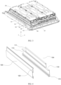
- FIG. 3 schematically shows a structure of a battery according to an embodiment of this application.
- the battery 10 may include a box 107 and at least one battery cell 100 accommodated in the box 107.
- the box 107 primarily serves the purpose of accommodating and holding the battery cell 100.
- the box 107 may be of a simple three-dimensional structure such as a rectangular structure or a cylindrical structure or a spherical structure, or may be of a complex three-dimensional structure formed by combining simple three-dimensional structures such as a rectangular structure or a cylindrical structure or a spherical structure. This is not limited in the embodiments of this application.
- FIG. 3 exemplarily shows a rectangular short box 107.
- the box 107 may be made of an alloy material such as an aluminum alloy or an iron alloy, a polymer material such as polycarbonate or polyisocyanurate foam, or a composite material produced from materials such as glass fiber and epoxy resin. This is not limited in the embodiments of this application either.
- the battery cell 100 may be a lithium-ion battery, a sodium-ion battery, a magnesium-ion battery, or the like. This is not limited in the embodiments of this application.
- the battery cell 100 may be cylindrical, flat, rectangular, or of other shapes, and this is not limited in the embodiments of this application either.
- the battery cells 100 are typically categorized into three types by packaging method: columnar battery cell, prismatic battery cell, and pouch battery cell, and this is not limited in the embodiments of this application either.
- Columnar battery cells can also be divided into cylindrical battery cells, polygonal prismatic battery cells, and the like based on a cross-sectional shape of a columnar surface.
- the battery cell 100 in this embodiment of this application typically includes an end cover, a housing, and a cell assembly.
- the end cover refers to a component that covers an opening of the housing to isolate an internal environment of the battery cell 100 from an external environment.
- a shape of the end cover may fit with that of the housing, so that the end cover can match the housing.
- the end cover may be made of a material with specified hardness and strength (for example, aluminum alloy), so that the end cover is less likely to deform when subjected to extrusion and collision, allowing the battery cell 100 to have higher structural strength and enhanced safety performance.
- the end cover may be provided with functional components such as an electrode terminal.
- the electrode terminal may be configured to be electrically connected to the cell assembly for outputting or inputting electric energy of the battery cell 100.
- the end cover may also be made of various materials, such as copper, iron, aluminum, stainless steel, aluminum alloy, or plastic, which are not particularly limited in the embodiments of this application.
- an insulator may also be disposed at an inner side of the end cover.
- the insulator can be configured to isolate electrical connection components in the housing from the end cover, reducing a risk of short circuit.
- the insulator may be made of plastic, rubber, or the like.
- the housing is an assembly configured to cooperate with the end cover to form an internal environment of the battery cell 100, where the formed internal environment can be used to accommodate the cell assembly, an electrolyte (not shown in the figure), and other components.
- the housing and the end cover may be independent components, an opening may be provided in the housing, and the end cover covers the opening to form the internal environment of the battery cell.
- the end cover and the housing may also be integrated.
- the end cover and the housing may form a shared connection surface before other components are disposed inside the housing, and then the end cover covers the housing when inside of the housing needs to be enclosed.
- the housing may be of various shapes and sizes, such as a rectangular shape, a cylindrical shape, and a hexagonal prism shape.
- the shape of the housing may be determined based on a specific shape and size of a cell assembly.
- the housing may be made of various materials, such as copper, iron, aluminum, stainless steel, aluminum alloy, and plastic, which are not particularly limited in the embodiments of this application.
- the cell assembly is a component in which electrochemical reactions take place in the battery cell 100.
- the cell assembly is mainly formed by winding or stacking a positive electrode plate and a negative electrode plate, and a separator is generally disposed between the positive electrode plate and the negative electrode plate.
- the parts with an active material on the positive electrode plate and the negative electrode plate constitute a body portion of the cell assembly, and the parts without active material on the positive electrode plate and the negative electrode plate respectively constitute tabs (not shown in the figure).
- a positive tab and a negative tab may both be located at one end of the body portion or be located at two ends of the body portion respectively.
- a positive electrode active substance and a negative electrode active substance react with an electrolyte, and the tabs are connected to the electrode terminals to form a current loop.
- FIG. 3 schematically shows a structure of a battery according to an embodiment of this application.
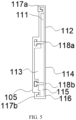
- FIG. 4 is a three-dimensional exploded view of a trough-shaped member and a cover plate in a battery according to an embodiment of this application.
- FIG. 5 is a schematic cross-sectional diagram of a structure of a trough-shaped member and a cover plate in a battery in an assembled state according to an embodiment of this application.
- FIG. 6 is a schematic exploded view of the trough-shaped member and the cover plate shown in FIG. 5 .
- the battery in this embodiment of this application includes a plurality of battery cells 100, a strap-shaped member 101 disposed fixedly relative to the plurality of battery cells 100, an electrical connection member 102 located adjacent to the strap-shaped member 101, and a trough-shaped member 104. As shown in FIG. 4 to FIG.
- the trough-shaped member 104 integrally has at least a first accommodation trough 111 (or a first accommodation trough 311 mentioned below) and a second accommodation trough 113 (or a second accommodation trough 313 mentioned below), where the strap-shaped member 101 is accommodated in the first accommodation trough 111 (or the first accommodation trough 311 mentioned below), the electrical connection member 102 is accommodated in the second accommodation trough 113 (or the second accommodation trough 313 mentioned below), and a portion of the trough-shaped member is located between the strap-shaped member 101 and the battery cells 100.
- a direction X in FIG. 3 is set as an arrangement direction of the plurality of battery cells 100; a direction Y is set as an extension direction of the strap-shaped member 101; and a direction Z is set as a height direction of the battery cell 100.
- the direction Z may also be referred to as a vertical direction.
- the strap-shaped member 101 may be a strap-shaped member that wraps around the plurality of battery cells 100 (hereinafter also referred to as a "battery cell assembly") to bundle these battery cells 100 into a group. These battery cells 100 are bundled via the strap-shaped member 101, so that the battery cell assembly can be bundled and fastened.
- the bundling of the battery cell assembly via the strap-shaped member 101 is implemented through the strap-shaped member 101 and a connector connecting ends of the strap-shaped member 101.
- a bundling position of the strap-shaped member 101 on the battery cell assembly is not particularly limited as long as the battery cell assembly can be reliably bundled.
- at least one strap-shaped member 101 is disposed at approximately a center of the battery cell 100 in the height direction or at a higher position, which is conducive to firm and reliable bundling of the battery cell assembly.
- one strap-shaped member 101 may be arranged in the height direction of the battery cell 100, or two or more strap-shaped members may be arranged side by side. In FIG. 3 , a case in which two strap-shaped members 101 are arranged side by side at intervals in the height direction of the battery cell 100 is used as an example for description.
- the strap-shaped member 101 may be a metal strap, for example, a steel strap.
- the strap-shaped member 101 can have some elasticity and flexibility, which can allow the battery cell 100 to expand to some extent during use.
- the strap-shaped member 101 can further be partially detached from the battery cell assembly to form a gap under action of external pulling force when being bundled on the battery cell assembly, to allow a portion of the trough-shaped member 104 to pass (details are described below).
- a degree of bundling tightness of the strap-shaped member 101 relative to the battery cell assembly can be adjusted as required.
- the electrical connection member 102 can be used for at least one of electrical connection between the battery cells 100, electrical connection between the battery cell 100 and an electric box connector 110, and electrical connection between the battery cell 100 and another electrical component.
- the electrical connection member 102 may be a relative high-voltage electrical connection member or low-voltage electrical connection member in the battery.
- the electrical connection member 102 is, for example, the high-voltage electrical connection member (also referred to as a "high-voltage bar").
- the high-voltage electrical connection member usually refers to a connection member that is primarily used for transmitting electrical energy of the battery.
- the electrical connection member 102 is made of a material with specified conductivity, and is usually made of a metal material such as aluminum or copper.
- the electrical connection member 102 is disposed near the strap-shaped member 101, for example, below the strap-shaped member 101, and the electrical connection member 102 is disposed substantially parallel to the strap-shaped member 101.
- Persons skilled in the art should know that such configuration is only one of the ways to achieve the objective of the present invention, and relative positions of the electrical connection member 102 and the strap-shaped member 101 are not limited to the manner shown in FIG. 3 .
- the trough-shaped member 104 is, for example, an integrally formed member.
- the trough-shaped member 104 can also be divided into two or three sections in its extension direction (direction Y in FIG. 3 ), but in consideration of installation convenience, reduction in the number of parts and the like, an integrally formed structure is preferred.
- the trough-shaped member 104 integrally has at least a first accommodation trough 111 (or a first accommodation trough 311 mentioned below) and a second accommodation trough 113 (or a second accommodation trough 313 mentioned below).
- the first accommodation trough is disposed abutting on the second accommodation trough in parallel in the height direction of the battery (direction Z in FIG. 3 ).
- the strap-shaped member 101 is accommodated in the first accommodation trough 111 (or the first accommodation trough 311 mentioned below), the electrical connection member 102 is accommodated in the second accommodation trough 113 (or the second accommodation trough 313 mentioned below).
- a relationship between the strap-shaped member 101, the electrical connection member 102, and dimensions of inner walls of the first and second accommodation troughs only needs to satisfy that the strap-shaped member 101 and the electrical connection member 102 can be accommodated in their respective accommodation troughs and are little spaced or substantially not spaced from the inner walls of the troughs. If the space is too large, on the one hand, a volume of the trough-shaped member 104 is large, which affects the grouping efficiency of the battery. On the other hand, it is possible that reliable fastening cannot be implemented, and adverse effects such as fracture due to fatigue or noise occur due to vibration or the like.
- the trough-shaped member 104 When the trough-shaped member 104 has been installed on the strap-shaped member 101, a portion of the trough-shaped member 104 is located between the strap-shaped member 101 and the battery cell assembly. In other words, the trough-shaped member 104 is hung on the strap-shaped member 101 via the first accommodation trough 111 (or the first accommodation trough 311 mentioned below), and is also subjected to bundling force of the strap-shaped member 101, so that the trough-shaped member 104 can be reliably installed on the strap-shaped member 101 and is uneasy to fall off.
- the strap-shaped member 101 is disposed fixedly relative to the plurality of battery cells (battery cell assembly), a portion of the trough-shaped member 104 is located between the strap-shaped member 101 and the battery cells (battery cell assembly), and the strap-shaped member 101 is accommodated in the first accommodation trough 111 (or 311) of the trough-shaped member 104, the trough-shaped member 104 is fixedly installed on the strap-shaped member 101.
- the electrical connection member 102 is accommodated in the second accommodation trough 113 (or 313) of the trough-shaped member 104, the electrical connection member 102 also has relatively fixed position, reliably fastening the electrical connection member 102. Because the electrical connection member 102 is reliably fastened, adverse effects such as fracture of the electrical connection member 102 in the battery due to fatigue are avoided, thereby improving reliability of the battery during use.
- the electrical connection member 102 is reliably fastened through the trough-shaped member 104 fastened to the strap-shaped member 101, and therefore, a short electric box with a shorter side wall can be used for the battery, which can reduce space occupied by the battery box and the like, so that as many battery cells as possible can be arranged in limited battery installation space, thereby improving energy density of the battery.
- a trough bottom plate 112 of the first accommodation trough 111 (or 311) is integrally connected with a trough bottom plate 114 (or 314) of the second accommodation trough 113 (or 313); the trough bottom plate 112 of the first accommodation trough 111 (or 311) is located between the strap-shaped member 101 and the battery cells 100; and the trough bottom plate 114 (or 314) of the second accommodation trough 113 (or 313) is located between the electrical connection member 102 and the battery cells 100.
- the accommodation trough can be composed of a trough bottom plate and trough side walls disposed upright relative to the trough bottom plate. Adjacent accommodation troughs can have integrally connected trough bottom plates, and share a trough side wall.
- the trough bottom plate 112 of the first accommodation trough 111 is integrally connected with a trough bottom plate 114 of the second accommodation trough 113, and therefore, the side wall (L-shaped trough side wall) 117a, a side wall (T-shaped trough side wall) 118a, and the trough bottom plate 112 of the first accommodation trough enclose accommodation space of the first accommodation trough 111.
- the side wall (T-shaped trough side wall) 118a, the side wall (T-shaped trough side wall) 118b, and the trough bottom plate 114 of the second accommodation trough 113 enclose accommodation space of the second accommodation trough 113.
- the trough bottom plate 112 of the first accommodation trough 311 is integrally connected with a trough bottom plate 314 of the second accommodation trough 313, and therefore, the side wall (L-shaped trough side wall) 117a, a side wall (T-shaped trough side wall) 118a, and the trough bottom plate 112 of the first accommodation trough enclose accommodation space of the first accommodation trough 311.
- the side wall (T-shaped trough side wall) 118b, the side wall (L-shaped trough side wall) 117b, and the trough bottom plate 314 of the second accommodation trough 313 enclose accommodation space of the second accommodation trough 313.
- the trough-shaped member 104 can be easily constructed into an integrally formed structure. Because the trough bottom plate 112 of the first accommodation trough 111 for accommodating the strap-shaped member 101 is located between the strap-shaped member and the battery cells, the trough-shaped member 104 is firmly fastened to the strap-shaped member 101 through a simple structure. Because the trough bottom plate 114 (314) of the second accommodation trough 113 (313) for accommodating the electrical connection member 102 is located between the electrical connection member 102 and the battery cells 100, the electrical connection member 102 can be reliably isolated from the battery cells 100, thereby reliably protecting the electrical connection member 102.
- the battery further includes a wire harness 103; the trough-shaped member 104 further integrally has a third accommodation trough 115 (315), and the wire harness 103 is accommodated in the third accommodation trough 115 (or 315); and the trough bottom plate 112 of the first accommodation trough, the trough bottom plate 114 (314) of the second accommodation trough, and a trough bottom plate 116 (316) of the third accommodation trough are integrally connected in a coplanar manner.
- the wire harness 103 may include a heating wire used for a thermal management system of the battery, a sampling wire used for the battery, and the like, and generally belongs to a low-voltage electrical connection member compared with the foregoing high-voltage electrical connection member.
- the wire harness 103 may include one or more wires.
- the third accommodation trough 115 (or 315) of the trough-shaped member 104 is configured to accommodate the wire harness 103.
- a positional relationship between the wire harness 103 and the third accommodation trough 115 (315) only needs to satisfy that the wire harness 103 can be accommodated in the accommodation trough, and is not particularly limited. But it is preferable to make the space between the wire harness 103 and the inner wall of the accommodation trough smaller in consideration of positioning of the wire harness 103 and miniaturization of the trough-shaped member 104.
- the side wall (T-shaped trough side wall) 118b, the side wall (L-shaped trough side wall) 117b, and the trough bottom plate 116 of the third accommodation trough enclose accommodation space of the third accommodation trough 115.
- the side wall (T-shaped trough side wall) 118a, the side wall (T-shaped trough side wall) 118b, and the trough bottom plate 316 of the third accommodation trough enclose accommodation space of the third accommodation trough 315.
- the trough bottom plate 112 of the first accommodation trough, the trough bottom plate 114 (314) of the second accommodation trough, and a trough bottom plate 116 (316) of the third accommodation trough are integrally connected in a coplanar manner.
- coplanar means that trough bottom plates of the three accommodation troughs are in the same plane.
- the trough-shaped member 104 can also fasten the electrical connection member and the wire harness.
- the trough-shaped member 104 further integrally has the third accommodation trough 115 (or 315) for accommodating the wire harness, the wire harness 103 can also be fastened without increasing the number of parts, which can ensure that the electrical connection member 102 around the battery, the wire harness 103, and the like are trimly arranged at designated positions. Because the trough bottom plates of the first, second, and third accommodation troughs are integrally connected in the coplanar manner, the integrally formed trough-shaped member has a simple structure, and the entire bottom surface of the trough-shaped member 104 can be attached to the battery cell in a surface contact method during installation, which improves installation stability.
- the first accommodation trough 111 (or 311), the second accommodation trough 113 (or 313), and the third accommodation trough 115 (or 315) each are strip-shaped, and the first accommodation trough 111 (or 311) is disposed parallel to at least one of the second accommodation trough 113 (or 313) and the third accommodation trough 115 (or 315); and the first accommodation trough 111 (or 311) is disposed abutting on the second accommodation trough 113 (or 313), or the first accommodation trough 111 (or 311) is disposed abutting on the third accommodation trough 115 (or 315).
- the first accommodation trough 111 (or 311)
- the second accommodation trough 113 (or 313)
- the third accommodation trough 115 (or 315) each form strip-shaped structures extending in the direction Y shown in FIG. 3 , or any two or all three of the accommodation troughs may alternatively be disposed in parallel.
- the first, second, and third accommodation troughs each are strip-shaped, and therefore are particularly suitable for accommodating the strap-shaped member 101, the electrical connection member 102, and the wire harness 103 in a strip shape.
- relative positions of the trough-shaped member 104, the strap-shaped member 101, the electrical connection member 102, and the wire harness 103 are fixed in a long range via the strip-shaped trough structures, and therefore, fastening force can be ensured in the long range, which can reliably avoid swinging or shaking of the electrical connection member 102, the wire harness 103, and the like.
- the foregoing designed trough-shaped member 104 is particularly suitable for a case in which extension directions of the strap-shaped member 101, the electrical connection member 102, and the wire harness 103 in the battery are substantially parallel.
- the first accommodation trough 111 may be disposed abutting on the second accommodation trough 113, or as shown in FIG. 8 , the first accommodation trough 311 may be disposed abutting on the third accommodation trough 315. Therefore, even if layout of the electrical connection member 102 and the wire harness 103 around the battery cells changes, the electrical connection member 102 and the wire harness 103 can be fastened via the trough-shaped members 104 with different structures.
- the first accommodation trough 111 (or 311) is disposed on an edge side of the trough-shaped member 104 at one end.
- the first accommodation trough 111 (or 311) is disposed on an edge side of the trough-shaped member 104 at one end.
- the first accommodation trough 11 is provided on the upper end edge of the trough-shaped member 104. In this way, to install the trough-shaped member 104 on the strap-shaped member 101, it is only necessary to insert one end edge of the trough-shaped member 104 (for example, the L-shaped trough side wall in FIG.
- a side wall (for example, the L-shaped trough side wall 117a in FIG. 3 ) on an edge side at one end that needs to exceed the strap-shaped member 101 can be made lower than the other side walls, which can reduce a distance between the strap-shaped member 101 and the battery cell assembly, and can reduce deformation of the strap-shaped member 101.
- the side wall on the edge side at one end lower, as long as the side wall can pass through the gap between the strap-shaped member 101 and the battery cell assembly.
- the first accommodation trough 111 (or 311) for accommodating the strap-shaped member 101 is located on an edge side of the trough-shaped member 104 at one end, to install the trough-shaped member 104 relative to the strap-shaped member 101, it is only necessary to let one end of the trough-shaped member 104 exceed the strap-shaped member through the gap between the strap-shaped member 101 and the battery cell 100, to clamp the trough-shaped member 104 (the first accommodation trough of the trough-shaped member) into the strap-shaped member 101, thereby facilitating installation.
- one or both end portions of the trough-shaped member 104 in an extension direction have an escape portion 119, and the escape portion 119 is formed by recessing the first accommodation trough 111 (or 311) relative to the second accommodation trough 113 (or 313) in the extension direction.
- the first accommodation trough 111 is shorter than the second accommodation trough 113, and therefore, notches are formed at two end portions of the first accommodation trough 111 in the extension direction, and the notch forms the escape portion 119.
- the end edge of the trough-shaped member 104 on the side of the first accommodation trough 111 is inserted into the gap between the strap-shaped member 101 and the battery cell assembly as mentioned above, interference and the like between two ends of the first accommodation trough 111 and the strap-shaped member 101 can be avoided during installation of the trough-shaped member 104 onto the strap-shaped member 101, thereby facilitating installation.
- the escape portions 119 are formed at both ends in the extension direction of the first accommodation trough 111, but the escape portion 119 may alternatively be formed at only one of the two ends.
- escape portion 119 is formed only at the end portion of the first accommodation trough 111 (or 311), without making the entire trough-shaped member 104 shorter, fastening and maintaining effects of the trough-shaped member 104 on the electrical connection member 102 can be ensured to the maximum extent.
- the battery further includes a cover plate 105 (or 205 or 305) covering the trough-shaped member 104.
- the cover plate can be a flat plate.
- the cover plate may be step-shaped. Specifically, a portion of the cover plate covering the first accommodation trough 111 (or 311) is closer to the trough bottom plate of the trough-shaped member 104 than a portion not covering the first accommodation trough 111 (or 311).
- the cover plate 105 (or 205 or 305) is installed on the trough-shaped member 104 by engaging an edge of the cover plate 105 with the side wall of the trough-shaped member 104.
- the cover plate covers the trough-shaped member, so that the strap-shaped member 104, the electrical connection member 102, the wire harness 103, and the like can be reliably held in their respective accommodation troughs, thereby preventing the trough-shaped member 104 from falling off the strap-shaped member 101 and preventing the electrical connection member 102, the wire harness 103, or the like from falling off the trough-shaped member 104.
- the trough-shaped member 104 has L-shaped trough side walls 117a and 117b (or 217a and 217b) with an L-shaped cross section and T-shaped trough side walls 118a and 118b with a T-shaped cross section; and the cover plate 105 (or 205 or 305) has engaging portions 121a and 121b (or 221a and 221b) engaged with the L-shaped trough side walls 117a and 117b (or 217a and 217b) of the trough-shaped member 104, and fitting troughs 123a and 123b fitted with the T-shaped trough side walls 118a and 118b.
- the L-shaped trough side walls 117a and 117b (or 217a and 217b) and the T-shaped trough side walls 118a and 118b of the trough-shaped member 104 are fitted with the corresponding engaging portions 121a and 121b (or 221a and 221b) and the fitting troughs 123a and 123b on the cover plate 105 (or 205 or 305), so that the cover plate 105 (or 205 or 305) can be installed on the trough-shaped member 104 and the cover plate is uneasy to fall off the trough-shaped member.
- the trough-shaped member 104 has L-shaped trough side walls 117 and 117b with a substantially L-shaped cross section at upper and lower end edges.
- the L-shaped trough side walls 117a and 117b have one end connected to the upper and lower end edges of the trough bottom plate of the trough-shaped member, and have another end forming L-shaped engaging space at a position closer to an inner side than the end edge, so that substantially concave first engaging portions 121a and 121b of the cover plate 105 that are formed at the end edge are located in the engaging space, and are engaged with the L-shaped trough side walls 117a and 117b, thereby installing the cover plate 105 onto the trough-shaped member 104.
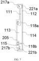
- the L-shaped trough side walls and the engaging portion can also be appropriately deformed, and a deformation example is described below with reference to FIG. 7 .
- the formed L-shaped trough side walls 217a and 217b of the trough-shaped member 104 in FIG. 7 are taller than the L-shaped trough side walls 117a and 117b in FIG. 5 , FIG. 6 , and FIG. 8 .
- the first engaging portions 221a and 221b of the cover plate 205 that are formed at the end edge are also substantially concave, but are thicker than the first engaging portions 121a and 121b in FIG. 5 , FIG. 6 , and FIG. 8 .
- the L-shaped trough side walls 217a and 217b are engaged with the first engaging portions 221a and 221b, so that the cover plate 205 is installed on the trough-shaped member 104.
- the engaging structure of the L-shaped trough side walls 217a and 217b and the first engaging portions 221a and 221b in the deformation example because the first engaging portions 221a and 221b are thicker, strength of the end edge of the cover plate 205 is higher.
- the T-shaped trough side wall of the trough-shaped member and the fitting trough of the cover plate are described in detail.
- the first accommodation trough 111 and the second accommodation trough 113 of the trough-shaped member 104 are separated by the T-shaped trough side wall 118a
- the second accommodation trough 113 and the third accommodation trough 115 are separated by the T-shaped trough side walls 118b.
- FIG. 5 to FIG. 7 the first accommodation trough 111 and the second accommodation trough 113 of the trough-shaped member 104 are separated by the T-shaped trough side wall 118a
- the second accommodation trough 113 and the third accommodation trough 115 are separated by the T-shaped trough side walls 118b.
- the first accommodation trough 311 and third accommodation trough 315 of the trough-shaped member 104 are separated by the T-shaped trough side wall 118a, and the third accommodation trough 315 and the second accommodation trough 313 are separated by the T-shaped trough side walls 118b.
- the T-shaped trough side wall means that a cross section of the side wall is substantially T-shaped.
- the first fitting trough 123a and the second fitting trough 123b are formed on the cover plates 105, 205, and 305, and each of the first fitting trough 123a and the second fitting trough 123b has trough space whose cross section is substantially T-shaped.
- the cover plate is installed on the trough-shaped member, the T-shaped trough side walls 118a and 118b on the side with the trough-shaped member are respectively inserted into the first fitting trough 123a and the second fitting trough 123b, so that movement of the cover plate and the trough-shaped member in the vertical direction and the horizontal direction (detachment direction of the cover plate and the trough-shaped member) is restricted.
- the L-shaped trough side wall and the T-shaped trough side wall extend along an extension direction of the trough-shaped member 104, and the L-shaped trough side wall is disposed on an end edge of the trough-shaped member.
- the cover plate 105 (or 205 or 305) can slide relative to the trough-shaped member 104 in its extension direction when the engaging portions 121a and 121b (or 221a and 221b) and the fitting troughs 123a and 123b of the cover plate are fitted with these side walls, so that the cover plate 105 (or 205 or 305) can be easily slid from an end of the trough-shaped member 104 in its extension direction to a designated position without falling off.
- the cover plate 105 (or 205 or 305) has rivet holes 120 and is fastened to a bracket 108 on a side with the trough-shaped member 104 via rivets (not shown in the figure).
- one rivet hole 120 is provided at each of two ends of the cover plate 105 (or 205 or 305) in the extension direction, and the cover plate is fastened to the bracket 108 on the side with the trough-shaped member 104 via the rivets or the like.
- positions and the number of rivet holes are not limited to those in the foregoing examples, and can be set based on an actual need.
- a plastic rivet can be used as the rivet.
- the cover plate 105 (or 205 or 305) can also be fastened to the bracket on the side with the trough-shaped member 104 via the rivets, the cover plate 105 (or 205 or 305) can be reliably positioned relative to the trough-shaped member 104, thereby avoiding an undesirable case in which the cover plate 105 (or 205 or 305) freely slides on the trough-shaped member 104 due to vibration or the like. That is, the cover plate 105 (or 205 or 305) is positioned relative to the trough-shaped member 104 in all the X-axis direction, the Y-axis direction, and the Z-axis direction.
- a material of at least one of the trough-shaped member 104 and the cover plate 105 is an insulating material.
- the trough-shaped member 102 and the cover plate 105 may be made of plastic, for example, may be formed by extrusion molding.
- the electrical connection member, the wire harnesses, and the like can be insulated from a surrounding metal member and the like, so that the electrical connection member, the wire harnesses, and the like can be reliably isolated and protected.
- the electrical connection member 102 is a high-voltage connection member.
- the high-voltage connection member mainly used to transmit electric energy of the battery can be reliably fastened and protected, which improves reliability of the key components of the battery during use and even the entire battery.
- the plurality of battery cells are an odd number of battery cells, and the high-voltage connection member electrically connects the battery cells with an electric box; or the plurality of battery cells form an odd number of battery modules, and the high-voltage connection member electrically connects the battery modules with the electric box.
- FIG. 2 shows battery cells 100a, 100b, and 100c.
- Positive and negative electrodes of the battery cell 100a and the battery cell 100b are connected, and positive and negative electrodes of the battery cell 100b and the battery cell 100c are connected.
- the negative electrode of the battery cell 100a is connected to a negative electrode of the electric box connector 110 through a high-voltage connection member, and the positive electrode of the battery cell 100c is connected to the positive electrode of the electric box connector 110 through a high-voltage connection member. It can be seen from FIG.
- the high-voltage connection member between the negative electrode of the battery cell 100a and the negative electrode of the electric box connector 110 is a long high-voltage connection member.
- the long high-voltage connection member can be the electric connector 102 in FIG. 3 .
- the trough-shaped member in this application is particularly suitable for maintaining and fastening such high-voltage connection member, which can avoid fracture of the high-voltage connection member due to fatigue caused when the high-voltage connection member is more prone to great vibration if the high-voltage connection member is long.
- FIG. 1 shows a vehicle as an example of an electric apparatus in this application.
- a third aspect of this application provides a battery assembling method.
- the assembling method includes the following steps: providing a plurality of battery cells 100, where a strap-shaped member 101 is disposed fixedly relative to the plurality of battery cells 100 (step S100); disposing a trough-shaped member 104 relative to the strap-shaped member 101 and arranging a portion of the trough-shaped member 104 between the strap-shaped member 101 and the battery cells 100, where the trough-shaped member 104 integrally has at least a first accommodation trough 111 (or 311) and a second accommodation trough 113 (or 313), and the strap-shaped member 101 is accommodated in the first accommodation trough 111 (or 311) (step S200); and installing an electrical connection member 102 by accommodating the electrical connection member 102 in the second accommodation trough 113 (or 313) (step S300).
- the strap-shaped member 101 is disposed fixedly relative to the plurality of battery cells 100, a portion of the trough-shaped member 104 is located between the strap-shaped member 101 and the battery cells 100, and the strap-shaped member 101 is accommodated in the first accommodation trough 111 (or 311) of the trough-shaped member, the trough-shaped member 104 is fixedly installed on the strap-shaped member 101.
- the electrical connection member 102 is accommodated in the second accommodation trough 113 (or 313) of the trough-shaped member, the electrical connection member 102 also has relatively fixed position, reliably fastening the electrical connection member 102. Because the electrical connection member 102 is reliably fastened, adverse effects such as fracture of the electrical connection member 102 in the battery due to fatigue are avoided, thereby improving reliability of the battery during use.
- the electrical connection member is reliably fastened through the trough-shaped member fastened to the strap-shaped member, and therefore, a short electric box with a shorter side wall can be used for the battery, which can reduce space occupied by the battery box and the like, so that as many battery cells as possible can be arranged in limited battery installation space, thereby improving energy density of the battery.
- the trough-shaped member 104 further includes a third accommodation trough 115 (or 315), and as shown in FIG. 10 , the assembling method further includes a step of installing a wire harness 103 by accommodating the wire harness 103 in the third accommodation trough 115 (or 315) (step S400).
- the wire harness 103 is accommodated in the third accommodation trough 115 (or 315) of the trough-shaped member, the wire harness can also be fastened and maintained without increasing the number of parts. Therefore, it can be ensured that the electrical connection member 102 around the battery, the wire harness 103, and the like are trimly arranged at designated positions.
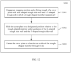
- the assembling method further includes the following step: installing a cover plate 105 (or 205 or 305) relative to the trough-shaped member 104 and fastening the cover plate 105 (or 205 or 305) relative to the trough-shaped member 104 (step S500).
- the cover plate 105 (or 205 or 305) covers the trough-shaped member 104, so that the strap-shaped member 101, the electrical connection member 102, the wire harness 103, and the like can be reliably held in their respective accommodation troughs, thereby preventing the trough-shaped member 104 from falling off the strap-shaped member 101 and preventing the electrical connection member 102, the wire harness 103, or the like from falling off the trough-shaped member 104.
- the cover plate 105 (or 205 or 305) is fastened relative to the trough-shaped member 104, an undesirable case in which the cover plate freely slides on the trough-shaped member due to vibration or the like can be avoided.
- the installing a cover plate relative to the trough-shaped member and fastening the cover plate relative to the trough-shaped member includes: engaging the engaging portions 121a and 121b (or 221a and 221b) and fitting troughs 123a and 123b of the cover plate 105 (or 205 or 305) with L-shaped trough side walls 117a and 117b (or 217a and 217b) and T-shaped trough side walls 118a and 118b of the trough-shaped member 104 (step S501) respectively; sliding the cover plate 105 (or 205 or 305) to a designated position relative to the trough-shaped member 104 under guidance of the L-shaped trough side walls 117a and 117b (or 217a and 217b) and the T-shaped trough side walls 118a and 118b (step S502); and fastening the cover plate 105 (or 205 or
- the L-shaped trough side walls 117a and 117b (or 217a and 217b) and the T-shaped trough side walls 118a and 118b of the trough-shaped member 104 are fitted with the corresponding engaging portions 121a and 121b (or 221a and 221b) and the fitting troughs 123a and 123b on the cover plate 105 (or 205 or 305), so that the cover plate 105 (or 205 or 305) can be installed on the trough-shaped member 104 and the cover plate 105 (or 205 or 305) is uneasy to fall off the trough-shaped member 104.
- the cover plate 105 (or 205 or 305) can slide relatively on the trough-shaped member 104 under guidance of the L-shaped trough side walls 117a and 117b (or 217a and 217b) and the T-shaped trough side walls 118a and 118b, the cover plate can be easily installed at a designated position from an end of the trough-shaped member 104 in the extension direction.
- the electrical connection member in the battery can be reliably fastened and maintained, so that fracture of the electrical connection member in the battery due to fatigue can be avoided, and reliability of the battery during use can be further improved. Certainly, reliability of the electric apparatus including the battery during use is correspondingly improved, and maintenance costs are reduced.
- space occupied by the battery box and the like can be reduced, thereby improving energy density of the battery.
- use efficiency, design freedom and the like of space around the battery in the electric apparatus including the battery are improved, and the number of times of replacing or charging the battery in the electric apparatus is reduced, and use costs are reduced.
- this embodiment provides an extrusion-molded trough-shaped member 104 and an extrusion-molded cover plate 105.
- the trough-shaped member 104 includes a first accommodation trough 111 for accommodating a steel strap, a second accommodation trough 113 for accommodating the electrical connection member 102, and a third accommodation trough 115 for accommodating the wire harnesses that are arranged vertically side by side.
- the trough-shaped member 104 is fastened to the strap-shaped member 101 made of the steel strap, thereby respectively fastening the electrical connection member (for example, the high-voltage connection member) 102 and the wire harness 103 to the strap-shaped member 101 that bundles the plurality of battery cells 100.
- the first accommodation trough 111, the second accommodation trough 113, and the third accommodation trough 115 are structures arranged vertically side by side, and are respectively configured to accommodate the strap-shaped member 101 made of the steel strap, the electrical connection member 102, and the wire harness 103.
- Length of the second accommodation trough 113 and the third accommodation trough 115 is equivalent to length of the electrical connection member 102 on an inner side (side of the electrical connection member 102 that faces the battery cell 100), to fasten the trough-shaped member 104 along the length direction of the electrical connection member 102 and avoid movement and detachment of the trough-shaped member 104.
- the first accommodation trough 111 is shorter than the second accommodation trough 113, so that the trough-shaped member 104 can pass through the inner side of the strap-shaped member 101 (side of the strap-shaped member 101 that faces the battery cell 100), and clamp the strap-shaped member 101.
- L-shaped anti-detachment structures are designed at upper and lower end edges of the cover plate 105, that is, the first engaging portion 121a and the second engaging portion 121b.
- T-shaped anti-detachment structures are designed in the middle, that is, the first fitting trough 123a and the second fitting trough 123b.
- the cover plate 105 is correspondingly fitted with the upright side walls of the trough-shaped member 104 through the first engaging portion 121a, the second engaging portion 121b, the first fitting trough 123a, and the second fitting trough 123b, to form a strap-shaped member accommodation cavity, an electrical connection member accommodation cavity, and a wire harness accommodation cavity that are isolated from each other shown in FIG. 5 .
- the cover plate 105 is further provided with rivet holes 120, and the rivet holes 120 fit holes (not shown) in the bracket 108 of the battery to prevent the cover plate 105 from moving and falling off along the length direction.
- the formed L-shaped trough side walls 217a and 217b are taller than the L-shaped trough side walls 117a and 117b in FIG. 5 , FIG. 6 , and FIG. 8 .
- the first engaging portions 221a and 221b of the cover plate 205 that are formed at the end edge are also substantially concave, but are thicker than the first engaging portions 121a and 121b in FIG. 5 , FIG. 6 , and FIG. 8 .
- the L-shaped trough side walls 217a and 217b are engaged with the first engaging portions 221a and 221b, so that the cover plate 205 is installed on the trough-shaped member 104.
- positions of the second accommodation trough 112 and the third accommodation trough 113 are changed, so that the third accommodation trough 113 is located between the first accommodation trough 111 and the second accommodation trough 112.
Landscapes
- Chemical & Material Sciences (AREA)
- Chemical Kinetics & Catalysis (AREA)
- Electrochemistry (AREA)
- General Chemical & Material Sciences (AREA)
- Engineering & Computer Science (AREA)
- Aviation & Aerospace Engineering (AREA)
- Battery Mounting, Suspending (AREA)
Applications Claiming Priority (1)
| Application Number | Priority Date | Filing Date | Title |
|---|---|---|---|
| PCT/CN2021/142226 WO2023123001A1 (zh) | 2021-12-28 | 2021-12-28 | 电池、用电装置及电池的组装方法 |
Publications (3)
| Publication Number | Publication Date |
|---|---|
| EP4404342A1 true EP4404342A1 (de) | 2024-07-24 |
| EP4404342A4 EP4404342A4 (de) | 2025-01-01 |
| EP4404342B1 EP4404342B1 (de) | 2026-03-18 |
Family
ID=86996985
Family Applications (1)
| Application Number | Title | Priority Date | Filing Date |
|---|---|---|---|
| EP21969379.3A Active EP4404342B1 (de) | 2021-12-28 | 2021-12-28 | Batterie, elektrische vorrichtung und batteriemontageverfahren |
Country Status (4)
| Country | Link |
|---|---|
| US (1) | US20240266666A1 (de) |
| EP (1) | EP4404342B1 (de) |
| CN (1) | CN116982203A (de) |
| WO (1) | WO2023123001A1 (de) |
Families Citing this family (1)
| Publication number | Priority date | Publication date | Assignee | Title |
|---|---|---|---|---|
| CN117199679A (zh) * | 2023-09-07 | 2023-12-08 | 欣旺达动力科技股份有限公司 | 一种电池包 |
Family Cites Families (6)
| Publication number | Priority date | Publication date | Assignee | Title |
|---|---|---|---|---|
| JP2011175743A (ja) * | 2010-02-23 | 2011-09-08 | Sanyo Electric Co Ltd | 電源装置及びこれを備える車両 |
| KR102079780B1 (ko) * | 2016-09-02 | 2020-02-20 | 주식회사 엘지화학 | 배터리 모듈용 스트랩, 이를 포함하는 배터리 모듈 및 스트랩 압착용 지그 |
| CN106450090B (zh) * | 2016-11-22 | 2020-04-07 | 湖南三迅新能源科技有限公司 | 动力电池模组 |
| DE102017216782A1 (de) * | 2017-09-22 | 2019-03-28 | Volkswagen Aktiengesellschaft | Batteriemodulgehäuse für ein Fahrzeug |
| CN108649149A (zh) * | 2018-05-16 | 2018-10-12 | 多氟多(焦作)新能源科技有限公司 | 电池盖板与极耳的连接结构及电池装配方法 |
| DE102018119051A1 (de) * | 2018-08-06 | 2020-02-06 | Webasto SE | Batteriegehäuse, Batteriesystem und Montageverfahren für ein Batteriesystem |
-
2021
- 2021-12-28 WO PCT/CN2021/142226 patent/WO2023123001A1/zh not_active Ceased
- 2021-12-28 EP EP21969379.3A patent/EP4404342B1/de active Active
- 2021-12-28 CN CN202180095636.7A patent/CN116982203A/zh active Pending
-
2024
- 2024-04-16 US US18/636,514 patent/US20240266666A1/en active Pending
Also Published As
| Publication number | Publication date |
|---|---|
| CN116982203A (zh) | 2023-10-31 |
| US20240266666A1 (en) | 2024-08-08 |
| WO2023123001A1 (zh) | 2023-07-06 |
| EP4404342A4 (de) | 2025-01-01 |
| EP4404342B1 (de) | 2026-03-18 |
Similar Documents
| Publication | Publication Date | Title |
|---|---|---|
| EP2388845B1 (de) | Batteriepack | |
| EP3671905A1 (de) | Batteriemodul mit einfacherer montage und einem sammelschienenrahmen | |
| US20240304918A1 (en) | Box of battery, battery, electrical apparatus, and manufacturing device for batteries | |
| US12183908B2 (en) | Battery, power consumption device, and method and device for producing battery | |
| EP4333172A1 (de) | Batteriezelle, batterie, elektrische vorrichtung sowie verfahren und vorrichtung zur herstellung der batteriezelle | |
| EP4681950A2 (de) | Batteriepack und fahrzeug damit | |
| CN101803068A (zh) | 用于二次电池的模块 | |
| EP3154108A1 (de) | Batteriemodul und batteriepack damit | |
| CN101647135A (zh) | 组装和保持蓄能电池的装置 | |
| US11862817B2 (en) | Energy storage apparatus | |
| KR20190064839A (ko) | 전장 어셈블리 및 상기 전장 어셈블리를 포함하는 배터리 팩 | |
| US20240266666A1 (en) | Battery, electric apparatus, and battery assembling method | |
| US20230361356A1 (en) | Battery unit, and battery, power consuming device and preparation apparatus associated therewith | |
| CN217114627U (zh) | 电池和用电装置 | |
| US20250070357A1 (en) | Battery and electrical device | |
| US12025677B2 (en) | Battery, electric apparatus, and method for preparing battery | |
| EP4456285A1 (de) | Logische zelle, sekundärbatteriemodul und sekundärbatteriepack damit | |
| EP4507083A1 (de) | Batteriezelle und herstellungsverfahren dafür sowie batterie und elektrische vorrichtung | |
| WO2023130387A1 (zh) | 电池、用电装置及电池的制造方法 | |
| CN220710582U (zh) | 采集装置、电池和用电装置 | |
| CN223414220U (zh) | 一种电池管理系统、电池系统和用电装置 | |
| CN223993372U (zh) | 电池装置及用电装置 | |
| CN120261897B (zh) | 电池装置、用电装置及储能装置 | |
| CN223871626U (zh) | 电池装置及用电装置 | |
| CN219626804U (zh) | 电池组件及用电装置 |
Legal Events
| Date | Code | Title | Description |
|---|---|---|---|
| STAA | Information on the status of an ep patent application or granted ep patent |
Free format text: STATUS: THE INTERNATIONAL PUBLICATION HAS BEEN MADE |
|
| PUAI | Public reference made under article 153(3) epc to a published international application that has entered the european phase |
Free format text: ORIGINAL CODE: 0009012 |
|
| STAA | Information on the status of an ep patent application or granted ep patent |
Free format text: STATUS: REQUEST FOR EXAMINATION WAS MADE |
|
| 17P | Request for examination filed |
Effective date: 20240417 |
|
| AK | Designated contracting states |
Kind code of ref document: A1 Designated state(s): AL AT BE BG CH CY CZ DE DK EE ES FI FR GB GR HR HU IE IS IT LI LT LU LV MC MK MT NL NO PL PT RO RS SE SI SK SM TR |
|
| RAP1 | Party data changed (applicant data changed or rights of an application transferred) |
Owner name: CONTEMPORARY AMPEREX TECHNOLOGY(HONG KONG) LIMITED |
|
| A4 | Supplementary search report drawn up and despatched |
Effective date: 20241129 |
|
| RIC1 | Information provided on ipc code assigned before grant |
Ipc: H01M 50/20 20210101AFI20241125BHEP |
|
| DAV | Request for validation of the european patent (deleted) | ||
| DAX | Request for extension of the european patent (deleted) | ||
| GRAP | Despatch of communication of intention to grant a patent |
Free format text: ORIGINAL CODE: EPIDOSNIGR1 |
|
| STAA | Information on the status of an ep patent application or granted ep patent |
Free format text: STATUS: GRANT OF PATENT IS INTENDED |
|
| INTG | Intention to grant announced |
Effective date: 20251022 |
|
| GRAS | Grant fee paid |
Free format text: ORIGINAL CODE: EPIDOSNIGR3 |
|
| GRAA | (expected) grant |
Free format text: ORIGINAL CODE: 0009210 |
|
| STAA | Information on the status of an ep patent application or granted ep patent |
Free format text: STATUS: THE PATENT HAS BEEN GRANTED |
|
| AK | Designated contracting states |
Kind code of ref document: B1 Designated state(s): AL AT BE BG CH CY CZ DE DK EE ES FI FR GB GR HR HU IE IS IT LI LT LU LV MC MK MT NL NO PL PT RO RS SE SI SK SM TR |
|
| REG | Reference to a national code |
Ref country code: CH Ref legal event code: F10 Free format text: ST27 STATUS EVENT CODE: U-0-0-F10-F00 (AS PROVIDED BY THE NATIONAL OFFICE) Effective date: 20260318 Ref country code: GB Ref legal event code: FG4D |