EP4403729A1 - System zum zusammenklappen und aufklappen von hangars - Google Patents
System zum zusammenklappen und aufklappen von hangars Download PDFInfo
- Publication number
- EP4403729A1 EP4403729A1 EP22869470.9A EP22869470A EP4403729A1 EP 4403729 A1 EP4403729 A1 EP 4403729A1 EP 22869470 A EP22869470 A EP 22869470A EP 4403729 A1 EP4403729 A1 EP 4403729A1
- Authority
- EP
- European Patent Office
- Prior art keywords
- hangars
- folding
- unfolding
- arched
- hangar
- Prior art date
- Legal status (The legal status is an assumption and is not a legal conclusion. Google has not performed a legal analysis and makes no representation as to the accuracy of the status listed.)
- Pending
Links
- 239000004411 aluminium Substances 0.000 claims description 6
- XAGFODPZIPBFFR-UHFFFAOYSA-N aluminium Chemical compound [Al] XAGFODPZIPBFFR-UHFFFAOYSA-N 0.000 claims description 6
- 229910052782 aluminium Inorganic materials 0.000 claims description 6
- 230000005540 biological transmission Effects 0.000 claims description 6
- 210000003456 pulmonary alveoli Anatomy 0.000 claims description 2
- 238000010276 construction Methods 0.000 description 12
- 229910000831 Steel Inorganic materials 0.000 description 5
- 239000010959 steel Substances 0.000 description 5
- 238000003860 storage Methods 0.000 description 5
- 208000018747 cerebellar ataxia with neuropathy and bilateral vestibular areflexia syndrome Diseases 0.000 description 4
- 238000009826 distribution Methods 0.000 description 4
- 239000012528 membrane Substances 0.000 description 3
- 239000002184 metal Substances 0.000 description 3
- 229910052751 metal Inorganic materials 0.000 description 3
- 238000000034 method Methods 0.000 description 3
- 230000003247 decreasing effect Effects 0.000 description 2
- 238000009434 installation Methods 0.000 description 2
- 238000012423 maintenance Methods 0.000 description 2
- 239000000463 material Substances 0.000 description 2
- 239000004215 Carbon black (E152) Substances 0.000 description 1
- 238000009825 accumulation Methods 0.000 description 1
- 238000004378 air conditioning Methods 0.000 description 1
- 239000000956 alloy Substances 0.000 description 1
- 229910045601 alloy Inorganic materials 0.000 description 1
- AZDRQVAHHNSJOQ-UHFFFAOYSA-N alumane Chemical group [AlH3] AZDRQVAHHNSJOQ-UHFFFAOYSA-N 0.000 description 1
- 238000009435 building construction Methods 0.000 description 1
- 239000002131 composite material Substances 0.000 description 1
- 238000005260 corrosion Methods 0.000 description 1
- 230000007797 corrosion Effects 0.000 description 1
- 230000005611 electricity Effects 0.000 description 1
- 238000005516 engineering process Methods 0.000 description 1
- 238000000605 extraction Methods 0.000 description 1
- 238000001125 extrusion Methods 0.000 description 1
- 239000004744 fabric Substances 0.000 description 1
- 229930195733 hydrocarbon Natural products 0.000 description 1
- 150000002430 hydrocarbons Chemical class 0.000 description 1
- 238000009413 insulation Methods 0.000 description 1
- 238000004519 manufacturing process Methods 0.000 description 1
- 230000007246 mechanism Effects 0.000 description 1
- 239000007769 metal material Substances 0.000 description 1
- 238000009428 plumbing Methods 0.000 description 1
- 238000000746 purification Methods 0.000 description 1
- 230000001932 seasonal effect Effects 0.000 description 1
- 238000000926 separation method Methods 0.000 description 1
- XLYOFNOQVPJJNP-UHFFFAOYSA-N water Substances O XLYOFNOQVPJJNP-UHFFFAOYSA-N 0.000 description 1
- 238000003466 welding Methods 0.000 description 1
Images

Classifications
-
- E—FIXED CONSTRUCTIONS
- E04—BUILDING
- E04H—BUILDINGS OR LIKE STRUCTURES FOR PARTICULAR PURPOSES; SWIMMING OR SPLASH BATHS OR POOLS; MASTS; FENCING; TENTS OR CANOPIES, IN GENERAL
- E04H15/00—Tents or canopies, in general
- E04H15/32—Parts, components, construction details, accessories, interior equipment, specially adapted for tents, e.g. guy-line equipment, skirts, thresholds
- E04H15/34—Supporting means, e.g. frames
- E04H15/36—Supporting means, e.g. frames arch-shaped type
- E04H15/38—Supporting means, e.g. frames arch-shaped type expansible, e.g. extensible in a fan type manner
-
- E—FIXED CONSTRUCTIONS
- E04—BUILDING
- E04B—GENERAL BUILDING CONSTRUCTIONS; WALLS, e.g. PARTITIONS; ROOFS; FLOORS; CEILINGS; INSULATION OR OTHER PROTECTION OF BUILDINGS
- E04B7/00—Roofs; Roof construction with regard to insulation
- E04B7/16—Roof structures with movable roof parts
- E04B7/163—Roof structures with movable roof parts characterised by a pivoting movement of the movable roof parts
-
- E—FIXED CONSTRUCTIONS
- E04—BUILDING
- E04H—BUILDINGS OR LIKE STRUCTURES FOR PARTICULAR PURPOSES; SWIMMING OR SPLASH BATHS OR POOLS; MASTS; FENCING; TENTS OR CANOPIES, IN GENERAL
- E04H6/00—Buildings for parking cars, rolling-stock, aircraft, vessels or like vehicles, e.g. garages
- E04H6/44—Buildings for parking cars, rolling-stock, aircraft, vessels or like vehicles, e.g. garages for storing aircraft
Definitions
- the present invention relates to a system for folding and unfolding hangars, especially suitable for parking and storing vehicles of all types, especially aerial vehicles, said hangar being configured to fold and unfold, automatically and/or manually, in either a position closed, in which there is generated an inner space covered by one or more canvas elements, or membranes, and arched structures, or an open position, wherein the hangar can be completely stowed and concealed, leaving the vehicle exposed to the outside.
- the present invention belongs to the technical field of construction, and more specifically to building constructions especially suitable for the storage of vehicles of all types, as well as the storage of other elements, by means of retractable articulated structures.
- Hangars are buildings specially used to store vehicles capable of navigating through the air, such as airplanes, helicopters or drones, under cover, for the purpose of protecting them from inclement weather, as well as carrying out in said vehicles, under suitable working conditions, the maintenance checks necessary for their use, these checks being very common in these means of transport.
- the main difference with industrial warehouses is that there are no intermediate pillars inside the building and the door opens to almost the entire available width to allow the aircraft, as well as the necessary machinery to perform maintenance, to enter and circulate therein.
- the design parameter that is usually taken to determine the dimensions of the hangar is usually the span of the vehicles to be stored, such as the distance between the tips of the wings in the case of airplanes, or the diameter of the rotor, in the case of helicopters.
- Hangar doors are also usually based on the same design parameters, since they must allow the introduction and extraction of the vehicle inside the hangar without the need to assemble and disassemble any of its parts.
- these doors are usually sliding and comprise several leaves that allow them to be rolled up or stored when they are stowed.
- the most common hangars on the market are metal steel constructions, based on a full web portal frame metal structure, with vertical walls and a roof made of sheet metal, which is sometimes bent and with an internal thermal and acoustic insulating filling.
- hangars In addition to fixed constructions, there are also removable hangars on the market, which can be erected and disassembled, depending on the needs, in short periods of time, and can be reassembled in different locations. These hangars are usually constructed with an aluminium structure with design profiles made by extrusion and using composite panels finished with steel sheet and assembled as tongue and groove joints, as enclosures.
- retractable hangars One of the constructions of this type that allows greater use of space are those known as retractable hangars. These hangars can fold part of their structure to take up less space, but with the exception that the problem of height is not solved, since a part of it always protrudes above ground level, with the problems that this entails when the vehicle to be stored is moved.
- hangars The operation of these hangars is usually based on a telescopic configuration of their walls and roof, so that when these parts are retracted or stowed, they can occupy less space but always keeping a part of the building (the largest) on the outside.
- the present invention consists of a novel system for folding and unfolding folding and retractable hangars which covers a need that until now only had partial solutions.
- the invention consists of a system for folding and unfolding hangars that comprises at least two flat and concentric arched structures, a canvas element connected to the two arched structures and two hinged, articulated joints, each connected to an end part of each arched structure.
- arched structures are, preferably, internally rigid, that is, they cannot be articulated or deformed internally, modifying their shape and/or size, but are articulated externally, in their connections with the hinged, articulated joints that they comprise in their two end parts of said structures. In this way, and preferably, the shape and size of these structures remain constant during their articulation, but not their orientation with respect to the joints or the base surface of the hangar.
- Each of these arched structures comprises at least one extruded profile, that is, they are manufactured from one or more profiles, so that, when joined together, they comprise a substantially flat and arched shape.
- arched structure is flat means that said profile or profiles are included in virtually a single plane, and the fact that they are concentric means that the centre of each arch is the same, or substantially the same, for all the structures included in the hangar.
- the canvas element can be any membrane or flexible element, made of any material suitable to act as a roof of a hangar, being sufficiently strong and resistant to outdoor weather conditions, maintaining the flexibility and lightness that allows its folding.
- At least one articulated joint which is connected to an end part of each arched structure of the hangar, is connected to rotational means, wherein said rotational means may comprise one or more motors, a system of pulleys, cables, etc.
- the articulated joints and the rotational means are configured to rotate the arched structures, positioning, through said rotation, the hangar in either a closed position, in which the arched structures are unfolded and each of them inclined at a different angle with respect to a base surface of the hangar, and the canvas element is extended and tightened; or an open position, in which the arched structures are folded, stowed towards the same side with respect to the articulated joint, and the canvas element is folded.
- a hangar In the closed position, a hangar is thereby created or constructed, and in the open position, the surface of said hangar is exposed to the outside so that it can be used as storage for elements or vehicles of any type, or as a free surface for landing and take-off.
- the arched structures are at different angles of rotation, so that the canvas that connects them will be tight, and the set of arched structures with said canvas can form a volume that can be partially or completely closed, allowing to protect the vehicle from inclemency.
- said structures as well as the canvas element or element comprised in the hangar can be concealed in a perimeter cavity or trench, under the base surface of said hangar, leaving said surface completely uncovered, where it can be used as a take-off and/or landing base, without there being nearby elements that could affect said operations.
- the alternative of raising the surface of the approach and take-off or storage area enough to be able to install a frame with a cavity where the structure is folded and stowed, where at least 80 cm above ground level is necessary to conceal said structure can be considered. That is, preferably, the hangar should be able to be completely concealed and stowed so that the base surface can be used as a take-off and landing surface.
- the rotational means comprise a steel pin in the form of a shaft with respect to which the arched structures rotate.
- the canvas element when the hangar is in the open position, the canvas element will remain stowed, rolled or collapsed, stowed in the described cavity or trenches, directly on the ground, or on supports of a small height, leaving said canvas loosely folded.
- this set will preferably be located with an approximate semicircle shape, occupying a small height, so that it is not an obstacle for manoeuvres to be carried out in the proximity thereof. All the elements in this set can be secured by connecting them to the ground to prevent any unwanted movement.
- This embodiment leads to a system for the construction of a hangar capable of folding and unfolding in a retractable manner, in a short time, and can be installed in the same space as a take-off and/or landing base, and it can be installed on airport platforms such as hangars for small aircraft and large drones.
- the system comprises three arched structures joined by their respective end parts to the two hinged, articulated joints; and two canvas elements each connected to two contiguous arched structures; wherein with the hangar in the closed position, with the arched structures inclined at a different angle with respect to the articulated joint, the two canvas elements are tightened and extended between each of these arched structures; therefore, the maximum separation size between the structures are determined by the width of the canvas element.
- all hangar structures can be of equal size, and remain stacked when stowed or folded, with very similar angles to the base surface.
- the decreasing size can be both the opening of the arch of each structure, as well as the width or thickness of each structure, with the smallest ones being able to fit into the inner spaces of the largest ones.
- the system comprises two canvas extensions each connected to an arched structure and connectable to a ground support.
- the end parts of each arched structure, joined by the articulated joints comprise an end connector to couple the rotational shaft.
- the hinged joint is connected to a foundation or footing of the base surface of the hangar. In this way, the arched structures as well as the canvases of the hangar support all their weight on said foundations.
- the arched structures comprised in the hangar each comprises different amplitude sizes, that is, radius of curvature, and wherein said arched structures are configured to fit with each other when said hangar is positioned in the position open.
- the rotational means comprise a motorised transmission system.
- said system will have a closed cable circuit in each of the articulated joints, connected to the end parts of the structures, which must work synchronously to rotate said structures.
- the cable is fastened at one point to the outer arch, and in this joint the force that must drive the arches in both directions will be transmitted.
- the cable will also pass through a pulley or similar device joined to the motor, which will provide the necessary drive, and through an arm provided with a pulley at its end to generate suitable deviation of the cable at the beginning of the opening or closing movements.
- the circuit may also include a tension pulley or a similar device to limit the range of tensile loads on the cable and to absorb variations in the length of the circuit in different positions.
- the transmission system is controllable by means of a remote control device.
- Said transmission system may also be operable manually while at the same time by means of remote control, or only manually in an alternative embodiment.
- the mechanisms for folding and unfolding the hangar by means of remote control can be activated through a radio signal, even from an aircraft, and without the intervention of ground personnel.
- the arched structures are polygonal, and each comprises a set of straight extruded profiles joined at the ends of said extruded profiles.
- arched structure is polygonal means that said structure is located in a portion of the plane limited by straight lines, wherein said straight lines are straight profiles joined at their ends, with small inclinations, forming an arch-shaped structure.
- the extruded profiles are joined together at the ends by means of inner connectors.
- These connectors can be made of aluminium, steel or another material with similar structural strength characteristics.
- the profiles and connectors are connected using rigid joints such as screwed or welded joints.
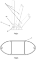
- the extruded profiles comprise a cross-section with an oval outer perimeter and at least one inner alveolus. This profile is constant along its entire length and is specially designed to withstand the loads to which the arched structures are subjected when the hangar is in the closed position, as well as during the process of rotating said structures.
- This oval profile can have a different size depending on the load to be supported, such as 500 by 200 mm, for the largest and smallest diameters, respectively, with sheet thicknesses between 5 to 8 mm, comprising up to three longitudinal cavities therein inside.
- said profile comprises two lateral alveoli and a central rectangular prismatic cavity.
- the profile design guarantees a simple, clean and aesthetically pleasing outer surface, helping to reduce the accumulation of dirt and rainwater and the corrosion they generate.
- the extruded profiles of each structure comprise at least one housing for fastening the canvas element. These housings can fasten the canvas elements without using additional elements.
- the extruded profiles are made of structural aluminium which, together with the special oval design of said profiles, make it suitable for the described use due to the structural strength and lightness it presents.
- the base surface of the hangar is configured to be covered by the canvas elements and comprises a heliport.
- said heliport can have an approximate diameter of about 20 metres, which allows the landing and take-off of an aircraft with sufficient space.
- each canvas element is configured to roll up into an arched structure.
- the canvas is automatically stowed on the arched structure to which it is connected, preventing the folds of said canvas from affecting the storage and fitting of the structures.
- the described system makes it possible to install hangars in places where there is a space problem and a hangar with existing technologies cannot be installed by performing the function of hangar and heliport alternately in the same space.
- the invention consists of a system for folding and unfolding folding and retractable hangars (1), the enclosure of which mainly comprises three flat and concentric arched structures (2) connected by means of two canvas elements (3), wherein said arched structures (2) are connected, through each of their two ends, to two articulated joints (5), respectively, and wherein two of these arched structures (2) are attached to two canvas extensions (7).
- These three flat arched structures (2) comprise a shape similar to that of a semicircle, the three structures (2) being concentric and of different diameters, so that one of these structures (2), the one located in the outermost part of Figure 1 , has a diameter slightly larger than the one located in an intermediate position, and this intermediate one being slightly larger than the one located on the inside.
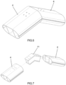
- Each arched structure (2) comprises a plurality of straight extruded profiles (4) made of structural aluminium, joined at their ends by means of inner connectors (11), as can be seen in Figures 6 and 7 , so that the shape of said structures (2) fits an arched polygonal shape, as can be seen in Figures 1 to 3 .
- the extruded profiles (4) comprise a slightly oval-shaped constant section, as can be seen in the section thereof shown in Figure 5 , which includes two lateral alveoli and a central rectangular prismatic cavity. These profiles also comprise two housings at the ends of the largest diameter of the oval, configured to fit with or connect to the canvas elements (3) and/or canvas extensions (7).
- each of the arched structures (2) comprise an extruded profile (4) connected to an articulated joint (5) by means of an end connector (10), wherein said articulated joint (5) is connected to rotational means (6).
- the joints between the extruded profiles (4) by means of the connectors (10, 11) are made by means of threaded joints, such as screws or bolts, although they can also be made using other rigid joints, such as rivets or welding.
- all the arched structures (2) have the same number of extruded profiles (4), which are arranged with a small gap between them, from the largest structure to the smallest one.
- the two articulated joints (5) are hinged, that is, they allow the rotation of the arched structures (2) only with respect to an axis, which is embodied in the form of a pin, located in said joints (5).
- the axes of the two articulated joints (5) are aligned but, if necessary, the arched structures (2) may not have an exact semicircle shape, and the ends of said structures (2) may be at different heights, depending on the geometry of the terrain and architectural needs, so articulated joints (5) may be deviated but always remain parallel.
- the arched structure (2) of larger diameter is connected to the one that comprises an intermediate diameter by means of a canvas element (3), and this intermediate structure (2) is also connected to the arched structure (2) of smaller diameter by means of another canvas element (3).
- the arched structures (2) of larger and smaller diameter are also each connected on a side opposite the connection with the canvas element (3), to a canvas extension (7) which can be connected to a ground support (8) to form a closed environment or building.
- the canvas elements (3) and the canvas extensions (7) have a shape similar to that of a spherical wedge, or a section, as can be seen in Figures 2 and 3 , and are flexible elements, such as membranes or fabrics that are specially designed to act as building enclosures. That is, they have high structural strength and wear resistance, a long useful life, and an insulation capacity as well as impermeability suitable for use as an enclosure, without losing these capacities due to folding.
- This arrangement of the arched structures (2) connected to the articulated joints (5), and the canvas elements (3) as well as the canvas extensions (7), allows the hangar (1) to function as a canopy, being able to be completely open, as shown in Figure 1 , with the arched structures (2) being folded, stowed and aligned, in an offset manner on the base surface (9).
- said arched structures (2) as well as the canvases (3, 7) can be concealed in a perimeter ditch or buried cavity, or on the side, off the runway, remaining fitted and secured, allowing the base surface (9) of the hangar (1) to be used as a take-off and/or landing surface, such as a heliport.
- the hangar (1) can be closed, as shown in Figure 3 , by rotating the arched structures (2) with respect to the articulated joints (5), extending and tightening the canvas elements (3) and the canvas extensions (7), and connecting said canvas extensions (7) to the ground support (8), generating a completely closed space or construction.
- the articulated joints (5) are connected to rotational means (6) that comprise a motorised transmission system, which in turn comprises a system of pulleys and cables connected to the arched structures (2) and one or more motors to provide the torque necessary to rotate said structures (2).
- rotational means (6) comprise a motorised transmission system, which in turn comprises a system of pulleys and cables connected to the arched structures (2) and one or more motors to provide the torque necessary to rotate said structures (2).
- the system is made up of a light structure, suitable to facilitate the folding and unfolding of its components due to the reduced weight of the aluminium and the canvas, and so that its assembly on elevated heliports or on platforms is not an impediment, since it can be concealed or covered under said heliport when it is open so as not to interfere with landings and take-offs of the aircraft parked therein.
- the system allows the hangar (1), in a closed state, with the arched structures (2) unfolded, to have an almost hemispherical shape, with an approximate diameter of 20 m and an approximate height of 10 m, sufficient to park aircraft.
- the hangar (1) When the hangar (1) is open, with its structures (2) folded, it may be completely embedded below the grade of the base surface (9), not being perceptible to the eye and, therefore, without affecting the use of said base surface (9) as a heliport.
- the definitive articulated construction is novel and covers a need that until now only had partial solutions, since there are no aircraft hangars on the market that allow them to be folded and unfolded quickly after landing and take-off, allowing a hangar to be installed in the same space as a heliport.
- the hangar (1) may have lighting systems, such as lights for night landing, or in low visibility conditions, lighting projectors/reflectors, elevated perimeter lights or guidance lighting systems for flight path alignment.
- lighting systems such as lights for night landing, or in low visibility conditions, lighting projectors/reflectors, elevated perimeter lights or guidance lighting systems for flight path alignment.
- it may also comprise painted signage, such as the heliport name, preferred approach and take-off direction signs, touchdown point signs and/or maximum allowable mass signs.
- the defined hangar (1) is compatible with fire protection installations to comply with the applicable regulations, which can be materialised through nozzles integrated in the base surface (9), or by means of monitors installed on the perimeter of said surface (9).
- the hangar (1) is also compatible with sanitation installations, with collection and purification systems for any hydrocarbon water that may exist, in such a way as to avoid producing any polluting discharges in the terrain where it is located.
- the electrical supply can be carried out through the distribution grid, although, if said connection is not possible, a secondary electrical supply system can be provided both to prevent failures in the primary grid, and in the even that there is no electrical distribution grid.
Landscapes
- Engineering & Computer Science (AREA)
- Architecture (AREA)
- Civil Engineering (AREA)
- Structural Engineering (AREA)
- Physics & Mathematics (AREA)
- Electromagnetism (AREA)
- Tents Or Canopies (AREA)
Applications Claiming Priority (2)
| Application Number | Priority Date | Filing Date | Title |
|---|---|---|---|
| ES202130862A ES2936384B2 (es) | 2021-09-16 | 2021-09-16 | Sistema de plegado y desplegado de hangares |
| PCT/ES2022/070533 WO2023041820A1 (es) | 2021-09-16 | 2022-08-11 | Sistema de plegado y desplegado de hangares |
Publications (2)
| Publication Number | Publication Date |
|---|---|
| EP4403729A1 true EP4403729A1 (de) | 2024-07-24 |
| EP4403729A4 EP4403729A4 (de) | 2025-01-01 |
Family
ID=85513789
Family Applications (1)
| Application Number | Title | Priority Date | Filing Date |
|---|---|---|---|
| EP22869470.9A Pending EP4403729A4 (de) | 2021-09-16 | 2022-08-11 | System zum zusammenklappen und aufklappen von hangars |
Country Status (3)
| Country | Link |
|---|---|
| EP (1) | EP4403729A4 (de) |
| ES (1) | ES2936384B2 (de) |
| WO (1) | WO2023041820A1 (de) |
Family Cites Families (11)
| Publication number | Priority date | Publication date | Assignee | Title |
|---|---|---|---|---|
| US3149703A (en) * | 1964-09-22 | De felice | ||
| GB521976A (en) * | 1938-11-30 | 1940-06-05 | Nicholas Straussler | Improvements in or relating to frames for collapsible structures for hangars and thelike |
| GB752911A (en) * | 1954-03-05 | 1956-07-18 | Lea Bridge Ind Ltd | Improvements in or relating to aircraft hangars and like shelters |
| FR2438716A1 (fr) * | 1978-10-09 | 1980-05-09 | Sprung Philip | Structure de construction |
| US4583331A (en) * | 1983-12-27 | 1986-04-22 | Clamshell Partners Ltd. | Frame supported structure with tensioned fabric panels |
| FR2594157B1 (fr) * | 1986-02-07 | 1991-03-15 | Sodeteg | Radome pliant. |
| CH670859A5 (de) * | 1986-08-25 | 1989-07-14 | Technikus J Felber Fa | |
| US5085240A (en) * | 1991-05-24 | 1992-02-04 | Littledeer Tomislav F | Shelter structure |
| GB0027343D0 (en) * | 2000-11-09 | 2000-12-27 | Mactaggart Scott | Aircraft protection |
| KR101023418B1 (ko) * | 2010-08-04 | 2011-03-25 | (주)에스피이엔씨 | 위장망 설치 장치 |
| US11142906B2 (en) * | 2018-07-06 | 2021-10-12 | Creative Tent International, Llc | Semi-permanent relocatable structure system |
-
2021
- 2021-09-16 ES ES202130862A patent/ES2936384B2/es active Active
-
2022
- 2022-08-11 EP EP22869470.9A patent/EP4403729A4/de active Pending
- 2022-08-11 WO PCT/ES2022/070533 patent/WO2023041820A1/es not_active Ceased
Also Published As
| Publication number | Publication date |
|---|---|
| EP4403729A4 (de) | 2025-01-01 |
| WO2023041820A1 (es) | 2023-03-23 |
| ES2936384A1 (es) | 2023-03-16 |
| ES2936384B2 (es) | 2024-03-07 |
Similar Documents
| Publication | Publication Date | Title |
|---|---|---|
| US11063553B2 (en) | Solar carports, solar-tracking carports, and methods | |
| US12294332B2 (en) | Solar carports, solar-tracking carports, and methods | |
| US8286391B2 (en) | Portable building | |
| US9222250B2 (en) | Folding building | |
| EP3818312B1 (de) | Sonnenfolgende carports | |
| AU697073B2 (en) | A cable-stay retractable skylight roof for stadium or arena or other structure and method of construction of same | |
| US20040261953A1 (en) | Sail shaped awnings | |
| US3699731A (en) | Modular building structure | |
| US9410312B2 (en) | Deployable portable shelter | |
| US7475514B2 (en) | Building structure folding and unfolding under the effect of the weight of the same and along vertical joint axes | |
| US4542759A (en) | Portable shelter | |
| WO2008093081A2 (en) | Modular car park deck | |
| US3461626A (en) | Hinged,collapsible,structural cover | |
| EP4403729A1 (de) | System zum zusammenklappen und aufklappen von hangars | |
| US3940892A (en) | Self-erecting aircraft structure | |
| US6044593A (en) | Free hanging canopy | |
| US4204372A (en) | Retractable roof | |
| US6202364B1 (en) | Prefabricated self-supporting building structure | |
| CN110566025B (zh) | 一种无人机停机库 | |
| CN2083602U (zh) | 可移动全预组折叠式房屋 | |
| RU2632831C1 (ru) | Модульный складной каркас здания | |
| CN118958481A (zh) | 一种医院空中连廊结构及其施工方法 | |
| RU68044U1 (ru) | Складное укрытие (варианты) | |
| CH642130A5 (en) | Process for forming a dome-shaped spatial roof and reticular structure for effecting said process | |
| SU1114750A1 (ru) | Складной блок сооружени |
Legal Events
| Date | Code | Title | Description |
|---|---|---|---|
| STAA | Information on the status of an ep patent application or granted ep patent |
Free format text: STATUS: THE INTERNATIONAL PUBLICATION HAS BEEN MADE |
|
| PUAI | Public reference made under article 153(3) epc to a published international application that has entered the european phase |
Free format text: ORIGINAL CODE: 0009012 |
|
| STAA | Information on the status of an ep patent application or granted ep patent |
Free format text: STATUS: REQUEST FOR EXAMINATION WAS MADE |
|
| 17P | Request for examination filed |
Effective date: 20240325 |
|
| AK | Designated contracting states |
Kind code of ref document: A1 Designated state(s): AL AT BE BG CH CY CZ DE DK EE ES FI FR GB GR HR HU IE IS IT LI LT LU LV MC MK MT NL NO PL PT RO RS SE SI SK SM TR |
|
| DAV | Request for validation of the european patent (deleted) | ||
| DAX | Request for extension of the european patent (deleted) | ||
| A4 | Supplementary search report drawn up and despatched |
Effective date: 20241202 |
|
| RIC1 | Information provided on ipc code assigned before grant |
Ipc: E04B 7/16 20060101ALI20241126BHEP Ipc: E04H 6/44 20060101ALI20241126BHEP Ipc: E04H 15/38 20060101AFI20241126BHEP |