EP4403725B1 - Saugroboter mit doppelauslassspirale zur schwimmbeckenreinigung - Google Patents
Saugroboter mit doppelauslassspirale zur schwimmbeckenreinigung Download PDFInfo
- Publication number
- EP4403725B1 EP4403725B1 EP23215995.4A EP23215995A EP4403725B1 EP 4403725 B1 EP4403725 B1 EP 4403725B1 EP 23215995 A EP23215995 A EP 23215995A EP 4403725 B1 EP4403725 B1 EP 4403725B1
- Authority
- EP
- European Patent Office
- Prior art keywords
- volute
- vacuum robot
- robot
- valve
- water
- Prior art date
- Legal status (The legal status is an assumption and is not a legal conclusion. Google has not performed a legal analysis and makes no representation as to the accuracy of the status listed.)
- Active
Links
Images


Classifications
-
- E—FIXED CONSTRUCTIONS
- E04—BUILDING
- E04H—BUILDINGS OR LIKE STRUCTURES FOR PARTICULAR PURPOSES; SWIMMING OR SPLASH BATHS OR POOLS; MASTS; FENCING; TENTS OR CANOPIES, IN GENERAL
- E04H4/00—Swimming or splash baths or pools
- E04H4/14—Parts, details or accessories not otherwise provided for
- E04H4/16—Parts, details or accessories not otherwise provided for specially adapted for cleaning
- E04H4/1654—Self-propelled cleaners
- E04H4/1663—Self-propelled cleaners the propulsion resulting from an intermittent interruption of the waterflow through the cleaner
-
- B—PERFORMING OPERATIONS; TRANSPORTING
- B60—VEHICLES IN GENERAL
- B60L—PROPULSION OF ELECTRICALLY-PROPELLED VEHICLES; SUPPLYING ELECTRIC POWER FOR AUXILIARY EQUIPMENT OF ELECTRICALLY-PROPELLED VEHICLES; ELECTRODYNAMIC BRAKE SYSTEMS FOR VEHICLES IN GENERAL; MAGNETIC SUSPENSION OR LEVITATION FOR VEHICLES; MONITORING OPERATING VARIABLES OF ELECTRICALLY-PROPELLED VEHICLES; ELECTRIC SAFETY DEVICES FOR ELECTRICALLY-PROPELLED VEHICLES
- B60L50/00—Electric propulsion with power supplied within the vehicle
- B60L50/50—Electric propulsion with power supplied within the vehicle using propulsion power supplied by batteries or fuel cells
- B60L50/60—Electric propulsion with power supplied within the vehicle using propulsion power supplied by batteries or fuel cells using power supplied by batteries
- B60L50/66—Arrangements of batteries
-
- B—PERFORMING OPERATIONS; TRANSPORTING
- B60—VEHICLES IN GENERAL
- B60L—PROPULSION OF ELECTRICALLY-PROPELLED VEHICLES; SUPPLYING ELECTRIC POWER FOR AUXILIARY EQUIPMENT OF ELECTRICALLY-PROPELLED VEHICLES; ELECTRODYNAMIC BRAKE SYSTEMS FOR VEHICLES IN GENERAL; MAGNETIC SUSPENSION OR LEVITATION FOR VEHICLES; MONITORING OPERATING VARIABLES OF ELECTRICALLY-PROPELLED VEHICLES; ELECTRIC SAFETY DEVICES FOR ELECTRICALLY-PROPELLED VEHICLES
- B60L2200/00—Type of vehicles
- B60L2200/32—Waterborne vessels
Definitions
- the present invention belongs to the field of swimming pool cleaning vacuum robots, in particular propulsion water jet vacuum robots, and relates more particularly to a vacuum robot comprising a double outlet volute allowing automatic reversal of the direction of movement.
- these robot vacuums move using wheels or tracks and are equipped with means of suction and filtration of debris and particles suspended in the water, and possibly cleaning means such as fixed or rotating brushes to unclog the walls and bottom of the pool.
- cleaning means such as fixed or rotating brushes to unclog the walls and bottom of the pool.
- robots of this type reverse their direction of movement when encountering an obstacle and move in a different direction between the outward and return movements (zigzag).
- Many means of obstacle detection and reversal of direction of movement are known.
- Some robots such as the one described in the document CN114687593 , use two separate motors, one motor for each direction of travel.
- the present invention aims to overcome all or part of the drawbacks of the prior art set out above by proposing a system with a fixed volute with double outlet, each outlet being provided with a valve.
- This very simple mechanical system insensitive to wear and blockage by debris which would not be stopped by the filter (filter torn or forgotten by the user) is therefore reliable and has a reduced manufacturing cost compared to known systems using rotating parts.
- the present invention relates to a submersible vacuum robot for cleaning artificial pools, in particular a swimming pool, comprising: a main body comprising a debris container; a filter; a volute with two discharge outlets; a suction and propulsion system producing a circulation of water in the volute and a propulsive water jet; and electrical supply means.
- This vacuum robot is remarkable in that the volute is fixed and comprises a valve at each of said outlets having an open position and a closed position, the positions of said valves alternating automatically in function of the direction of water circulation in the volute so as to reverse the direction of the propulsive water jet, and therefore the direction of movement of the robot.
- the suction and propulsion system comprises an electric motor and a centrifugal turbine coupled to the motor, the rotation of said turbine in one direction producing a circulation of water in the volute in the same direction.
- the turbine can have blades that can be oriented depending on its direction of rotation.
- each valve has a position opposite that of the other valve when the suction and propulsion system is in operation, and a default open position when said system is stopped.
- each valve is subjected to an elastic restoring force which tends to maintain it in its open position.
- the valves are monostable, with the open position as the rest position.
- the restoring force is provided by a torsion spring, placed in a hinge, or by flexibility of the valve itself.
- the suction and propulsion system is configured to reverse the direction of water circulation in the volute when the robot comes to a stop against an obstacle.
- the robot includes, for example, a stop sensor to control the reversal of the direction of water circulation in the volute.
- the electrical power supply means comprise an electric battery placed in a sealed compartment to give the robot an autonomous character.
- the robot further comprises trajectory deviation means such as a deflector of the propulsive water jet, so that the robot does not follow the same trajectory on the outward and return journeys.
- trajectory deviation means such as a deflector of the propulsive water jet
- double position volute or simply “double volute” designates a volute having two opposite outlets.
- the two outlets of a double volute can be diametrically opposed as in the example which will be described.
- THE figures 1 to 5 represent the different views of a submersible vacuum robot 100 with double volute, comprising a main body 10 consisting of a debris container 11 and a cover 12, a suction and propulsion system placed in said body and allowing the suction of water from the pool before its filtration and its discharge in the form of a propulsive water jet, and a volute 20 called double because it has two outlets 21a and 21b discharging, one at a time, the water sucked in according to the direction of movement of the robot.
- the vacuum robot 100 further comprises a filter placed in the debris bin 11, electrical power supply means such as an electric battery, a switch 50, and movement means, in particular drive wheels 41, swivel casters 42 and rollers 43.
- the main body 10, according to the illustrated embodiment, has a compact shape for better stability and a substantially hexagonal outline to better interact with obstacles and reach the corners of the pool.
- a substantially hexagonal outline to better interact with obstacles and reach the corners of the pool.
- other shapes and dimensions remain possible.
- the main body 10 is made of two separable parts which are the debris bin 11 and the cover 12. These two parts are assembled in a reversible manner and locked by closing means 13, in particular lever clasps as in the example illustrated. This allows rapid access to the interior of the main body 10 in order to empty and clean the debris bin 11, or to carry out maintenance on the robot.
- the debris container 11 defines an interior volume for collecting the debris sucked up and retained by the filter, and comprises one or more suction inlets 111 visible on the Figure 5 .
- the suction mouths 111 are preferably offset and have reduced sections to increase the suction speed and, therefore, the depression at the inlet of the suction duct, for more efficient suction.
- the cover 12 further comprises gripping means 122 arranged on one side and the other of the robot 100 and allowing the user to open said cover or simply to lift the robot.
- the gripping means 122 are produced in an arcuate structure partially covering the cover 12.
- the suction and propulsion system corresponds to an electrohydraulic power unit and typically comprises an electric motor and a centrifugal turbine coupled thereto, with a one- or multi-stage reduction mechanism in between.
- the turbine is placed in the volute 20 to form the suction pump. Indeed, the rotation of the centrifugal turbine, driven by the motor, produces a suction of the water and its discharge at high speed, through one of the outlets 21a or 21b of the volute.
- Outlets 21a and 21b are nozzles discharging the sucked water in the form of a water jet to propel the robot by reaction in the opposite direction to the direction of the water jet.
- FIG. 6 partially represents the vacuum robot 100 with the waterproof compartment removed, revealing the volute 20 and its two outlets 21a and 21b.
- the suction and propulsion system comprises an electric motor 31, placed partially under the hood 12, and a centrifugal turbine 32, with four or five blades for example, placed in the center of the volute 20.
- the suction and propulsion system also comprises, between the motor 31 and the turbine 32, reduction gears not shown, of which only the first gear mounted on the motor shaft is visible.
- the electric motor 31, and therefore the turbine 32 can rotate in both directions and thus allow the volute 20 to reverse the direction of movement of the robot 100 thanks to two valves 22a and 22b mounted respectively at the outlets 21a and 21b.
- each valve 22 has two positions: an open position clearing the passage of the corresponding outlet 21; and a closed position blocking said outlet.
- the positions of a valve alternate with the positions of the other flap during operation of the robot 100 and impose its direction of movement on the latter. In other words, when one flap is open, the other is closed and vice versa.
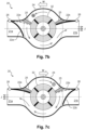
- FIG. 7a represents the volute 20 when the robot is at rest, that is to say when the turbine 32, and therefore the robot, is stationary.
- the valves 22a and 22b both occupy an open position, which is their default position, and therefore leave the outlets 21a and 21b clear.
- each valve 22 is pressed either directly against an adjacent wall 24 of the volute 20, as is the case of the valve 22b on the Figure 6 , either against a stop 25 as shown in the Figures 7a to 7c
- This open position is maintained elastically thanks to a restoring force in the absence of pressure exerted by the water.
- the capets 22 can either be articulated via an elastic means (torsion spring), or have structural elasticity (flexibility).
- each valve 22 is articulated on a hinge comprising a torsion spring 23 which tends to return the valve to its open position.
- the valves 22 are preferably rigid, but can perfectly be semi-rigid, or even flexible.
- valves 22 are flexible and can deform between the open position and the closed position.
- the valves are not articulated, but embedded at their attachment points 26.
- valves 22 are sized to switch from the open position to the closed position under the effect of the pressure of the water ejected by the turbine 32 in this direction, and from the closed position to the open position under the effect of the return force.
- FIG. 7b represents the volute 20 when the robot moves in the direction indicated by the arrow M (to the left of the figure). This direction of movement is due to the rotation of the turbine 32 in the positive direction, indicated by the symbol + on the Figure 7b , allowing a circulation of the water sucked in the same direction to be generated, which closes the valve 22a (left valve in the figure) while keeping the opposite valve 22a open, thus creating a jet of water J unidirectional through outlet 21b which remains open. The water thus ejected creates a propulsive force in the opposite direction according to the principle of action and reaction.
- Figure 7c represents the volute 20 when the robot moves in the opposite direction to the first and indicated by the arrow M (to the right of the figure).
- the turbine 32 rotates in the negative direction, indicated by the symbol - on the Figure 7c , and generates a circulation of the sucked water in the same direction, thus closing the valve 22b (right valve in the figure) and leaving open the opposite valve 22a and therefore the corresponding outlet 21a.
- the resulting water jet J comes out through this outlet 21a and propels the robot in the opposite direction.
- each valve 22 has a sufficient surface area on which the orthoradial pressure of the water is exerted when said valve is in the open position.
- this surface corresponds to a bent end 221 of the valve 22, while in the embodiment of the Figures 7a to 7b , this surface is accessible through a window 251 provided in the stops 25 as shown in section A - A of the Figure 7a .
- the vacuum robot 100 can then move bidirectionally to avoid obstacles, reversing its direction of movement when it encounters an obstacle, thanks to the reversal of the direction of rotation of the turbine 32 and more fundamentally of the direction of rotation of the drive shaft of the motor 31.
- the reversal of the direction of rotation of the motor 31 occurs when the robot 100 is immobilized against an obstacle such as a swimming pool wall.
- the robot 100 is equipped for this purpose with a sensor making it possible to detect the stopping of the robot 100.
- a sensor may be an inertial, gyroscopic, Hall effect, hydrodynamic sensor, or any other type suitable for the present application.
- the command to reverse the direction of rotation of motor 31, based on information from the robot stop sensor, is controlled by the robot's electronic card.
- the robot 100 may include means using one or more steerable wheels, an articulated axle or deflectors to deflect the propulsive water jet at a greater or lesser angle.
- the robot can optionally have fixed or rotating brushes to improve cleaning efficiency, especially when the bottom is dirty.
- the robot vacuum cleaner may be powered by mains electricity via an electric cable, have an integrated water treatment diffuser, have a motor located outside the main body to increase the volume of the debris compartment, etc.
Landscapes
- Engineering & Computer Science (AREA)
- Architecture (AREA)
- Civil Engineering (AREA)
- Structural Engineering (AREA)
- Sustainable Energy (AREA)
- Sustainable Development (AREA)
- Life Sciences & Earth Sciences (AREA)
- Power Engineering (AREA)
- Transportation (AREA)
- Mechanical Engineering (AREA)
- Cleaning In General (AREA)
- Electric Vacuum Cleaner (AREA)
- Electric Suction Cleaners (AREA)
- Structures Of Non-Positive Displacement Pumps (AREA)
- Nozzles For Electric Vacuum Cleaners (AREA)
Claims (10)
- Tauchsaugroboter (100) zur Reinigung von künstlichen Becken, umfassend: einen Hauptkörper (10), der einen Schmutzbehälter (11) umfasst; einen Filter; eine Spirale (20) mit zwei Auslassöffnungen (21a, 21b); ein Saug- und Antriebssystem (31, 32), das eine Wasserzirkulation in der Spirale und einen Treibwasserstrahl erzeugt; und elektrische Versorgungsmittel, wobei die Spirale feststehend ist und an jedem der Auslässe eine Klappe (22a, 22b) mit einer offenen und einer geschlossenen Stellung aufweist, dadurch gekennzeichnet, dass sich die Stellungen der Klappen in Abhängigkeit von der Richtung des Wasserflusses in der Spirale automatisch abwechseln, so dass die Richtung des Treibwasserstrahls umgekehrt wird.
- Saugroboter nach Anspruch 1, wobei das Saug- und Antriebssystem (31, 32) einen Elektromotor (31) und eine mit dem Motor gekoppelte Zentrifugalturbine (32) umfasst, wobei die Drehung der Turbine in eine Richtung eine Wasserzirkulation in der Spirale (20) in derselben Richtung erzeugt.
- Saugroboter nach Anspruch 2, wobei die Turbine (32) entsprechend ihrer Drehrichtung schwenkbare Schaufeln aufweist.
- Saugroboter nach einem der vorhergehenden Ansprüche, wobei jede Klappe (22a, 22b) eine gegenüberliegende Stellung zur anderen Klappe aufweist, wenn das Saug- und Antriebssystem (31, 32) in Betrieb ist, und eine standardmäßig geöffnete Stellung, wenn das System ausgeschaltet ist.
- Saugroboter nach einem der vorhergehenden Ansprüche, wobei jede Klappe (22a, 22b) einer elastischen Rückstellkraft ausgesetzt ist, die dazu tendiert, sie in ihrer geöffneten Position zu halten.
- Saugroboter nach Anspruch 5, wobei die Rückstellkraft durch eine Torsionsfeder (23) oder durch eine Flexibilität der Klappe (22a, 22b) gewährleistet ist.
- Saugroboter nach einem der vorhergehenden Ansprüche, wobei das Saug- und Antriebssystem (31, 32) so eingerichtet ist, dass es die Richtung des Wasserflusses in der Spirale (20) umkehrt, wenn der Roboter gegen ein Hindernis stoppt.
- Saugroboter nach Anspruch 7, mit einem Stoppsensor zum Steuern der Umkehrung der Richtung des Wasserflusses in der Spirale (20).
- Saugroboter nach einem der vorhergehenden Ansprüche, wobei die Stromversorgungsmittel eine elektrische Batterie umfassen, die in einem dichten Fach (121) platziert ist.
- Saugroboter nach einem der vorhergehenden Ansprüche, ferner mit Wegumlenkmitteln wie einer Ablenkvorrichtung für den Treibwasserstrahl.
Applications Claiming Priority (1)
| Application Number | Priority Date | Filing Date | Title |
|---|---|---|---|
| FR2300511A FR3145176B1 (fr) | 2023-01-19 | 2023-01-19 | Robot aspirateur à volute double sortie pour le nettoyage de piscines |
Publications (3)
| Publication Number | Publication Date |
|---|---|
| EP4403725A1 EP4403725A1 (de) | 2024-07-24 |
| EP4403725B1 true EP4403725B1 (de) | 2025-05-21 |
| EP4403725C0 EP4403725C0 (de) | 2025-05-21 |
Family
ID=85726900
Family Applications (1)
| Application Number | Title | Priority Date | Filing Date |
|---|---|---|---|
| EP23215995.4A Active EP4403725B1 (de) | 2023-01-19 | 2023-12-12 | Saugroboter mit doppelauslassspirale zur schwimmbeckenreinigung |
Country Status (4)
| Country | Link |
|---|---|
| US (1) | US20240247513A1 (de) |
| EP (1) | EP4403725B1 (de) |
| CN (1) | CN118361139A (de) |
| FR (1) | FR3145176B1 (de) |
Families Citing this family (1)
| Publication number | Priority date | Publication date | Assignee | Title |
|---|---|---|---|---|
| US20260103910A1 (en) * | 2024-10-16 | 2026-04-16 | Zodiac Pool Care Europe | Jet cleaner for swimming pools and spas |
Family Cites Families (9)
| Publication number | Priority date | Publication date | Assignee | Title |
|---|---|---|---|---|
| US6412133B1 (en) * | 1999-01-25 | 2002-07-02 | Aqua Products, Inc. | Water jet reversing propulsion and directional controls for automated swimming pool cleaners |
| FR2896005B1 (fr) * | 2006-01-11 | 2008-04-04 | Max Roumagnac | Robot nettoyeur de piscine |
| FR3041982B1 (fr) * | 2015-10-05 | 2017-11-24 | Max Roumagnac | Robot de nettoyage de piscine autonome |
| CN112641378B (zh) | 2019-10-11 | 2023-10-24 | 宁波市普世达泳池用品有限公司 | 水池清洁电动机器人 |
| CN213049697U (zh) * | 2020-08-14 | 2021-04-27 | 宁波市普世达泳池用品有限公司 | 水池清洁电动机器人 |
| CN112591067B (zh) | 2020-12-17 | 2022-05-10 | 淮安普乐菲智能科技有限公司 | 一种可控双向喷射推进器 |
| CN112623173B (zh) | 2020-12-17 | 2022-01-14 | 淮安普乐菲智能科技有限公司 | 一种可控双向换向机构 |
| CN114687593B (zh) | 2022-04-28 | 2025-05-27 | 浙江阔创科技有限公司 | 一种泳池吸污机及其控制方法 |
| CN114837476A (zh) | 2022-05-13 | 2022-08-02 | 浙江斯普智能科技股份有限公司 | 一种水下清洁机器人 |
-
2023
- 2023-01-19 FR FR2300511A patent/FR3145176B1/fr active Active
- 2023-12-12 EP EP23215995.4A patent/EP4403725B1/de active Active
- 2023-12-18 US US18/543,844 patent/US20240247513A1/en active Pending
- 2023-12-20 CN CN202311763465.8A patent/CN118361139A/zh active Pending
Also Published As
| Publication number | Publication date |
|---|---|
| US20240247513A1 (en) | 2024-07-25 |
| FR3145176A1 (fr) | 2024-07-26 |
| EP4403725A1 (de) | 2024-07-24 |
| EP4403725C0 (de) | 2025-05-21 |
| CN118361139A (zh) | 2024-07-19 |
| FR3145176B1 (fr) | 2025-01-17 |
Similar Documents
| Publication | Publication Date | Title |
|---|---|---|
| EP2513393B1 (de) | Reinigungsgerät für eine unterwasseroberfläche mit rotation beim hochziehen | |
| CA2709851C (fr) | Appareil nettoyeur de surface immergee a dispositif de filtrage demontable | |
| EP2513392B1 (de) | Reinigungsgerät für eine unterwasseroberfläche mit einem einzigen elektrisch- reversiblen antrieb- und pumpenmotor | |
| EP2235291B1 (de) | Vorrichtung zur reinigung einer untergetauchten fläche mit leichtem ablass | |
| EP2235297B1 (de) | Vorrichtung zur reinigung einer untergetauchten fläche mit einem abtrennbaren schmutzkreislauf | |
| EP2235295B1 (de) | Vorrichtung zur reinigung einer untergetauchten fläche und mit einem pumpmotor ausserhalb des hydraulischen systems | |
| EP2235298B1 (de) | Vorrichtung zur reinigung einer untergetauchten fläche mit wirbelfiltration | |
| EP2235296B1 (de) | Vorrichtung zur reinigung einer untergetauchten fläche mit abgewinkeltem filtrationssystem | |
| EP2240653B1 (de) | Vorrichtung zur reinigung einer untergetauchten fläche mit einer bürstenvorrichtung, die durch glieder zum antrieb der vorrichtung auf der untergetauchten fläche angetrieben wird | |
| EP2255049B1 (de) | Reinigungsvorrichtung für eine unterwasseroberfläche mit protuberanz zur zuflussbeschleunigung | |
| EP2235294B1 (de) | Vorrichtung zur reinigung einer untergetauchten fläche mit einem einlasskanal mit nicht gleichförmigem querschnitt | |
| WO2011073594A1 (fr) | Appareil nettoyeur de surface immergée à giration par au moins un organe roulant non moteur décalé latéralement | |
| FR2954378A1 (fr) | Appareil nettoyeur de surface immergee a cabrage hydraulique | |
| FR2934630A1 (fr) | Appareil roulant nettoyeur de surface immergee a flux d'entrainement orientable. | |
| EP3712358B1 (de) | Autonomer roboter mit alternierender absaugung für die reinigung von schwimmbädern | |
| EP4403725B1 (de) | Saugroboter mit doppelauslassspirale zur schwimmbeckenreinigung | |
| FR3154424A3 (fr) | Robot électrique pour le nettoyage de piscines |
Legal Events
| Date | Code | Title | Description |
|---|---|---|---|
| PUAI | Public reference made under article 153(3) epc to a published international application that has entered the european phase |
Free format text: ORIGINAL CODE: 0009012 |
|
| STAA | Information on the status of an ep patent application or granted ep patent |
Free format text: STATUS: THE APPLICATION HAS BEEN PUBLISHED |
|
| AK | Designated contracting states |
Kind code of ref document: A1 Designated state(s): AL AT BE BG CH CY CZ DE DK EE ES FI FR GB GR HR HU IE IS IT LI LT LU LV MC ME MK MT NL NO PL PT RO RS SE SI SK SM TR |
|
| STAA | Information on the status of an ep patent application or granted ep patent |
Free format text: STATUS: REQUEST FOR EXAMINATION WAS MADE |
|
| 17P | Request for examination filed |
Effective date: 20241219 |
|
| GRAP | Despatch of communication of intention to grant a patent |
Free format text: ORIGINAL CODE: EPIDOSNIGR1 |
|
| STAA | Information on the status of an ep patent application or granted ep patent |
Free format text: STATUS: GRANT OF PATENT IS INTENDED |
|
| INTG | Intention to grant announced |
Effective date: 20250305 |
|
| GRAS | Grant fee paid |
Free format text: ORIGINAL CODE: EPIDOSNIGR3 |
|
| GRAA | (expected) grant |
Free format text: ORIGINAL CODE: 0009210 |
|
| STAA | Information on the status of an ep patent application or granted ep patent |
Free format text: STATUS: THE PATENT HAS BEEN GRANTED |
|
| AK | Designated contracting states |
Kind code of ref document: B1 Designated state(s): AL AT BE BG CH CY CZ DE DK EE ES FI FR GB GR HR HU IE IS IT LI LT LU LV MC ME MK MT NL NO PL PT RO RS SE SI SK SM TR |
|
| REG | Reference to a national code |
Ref country code: GB Ref legal event code: FG4D Free format text: NOT ENGLISH |
|
| REG | Reference to a national code |
Ref country code: CH Ref legal event code: EP |
|
| REG | Reference to a national code |
Ref country code: DE Ref legal event code: R096 Ref document number: 602023003611 Country of ref document: DE |
|
| REG | Reference to a national code |
Ref country code: IE Ref legal event code: FG4D Free format text: LANGUAGE OF EP DOCUMENT: FRENCH |
|
| U01 | Request for unitary effect filed |
Effective date: 20250605 |
|
| U07 | Unitary effect registered |
Designated state(s): AT BE BG DE DK EE FI FR IT LT LU LV MT NL PT RO SE SI Effective date: 20250613 |
|
| PG25 | Lapsed in a contracting state [announced via postgrant information from national office to epo] |
Ref country code: ES Free format text: LAPSE BECAUSE OF FAILURE TO SUBMIT A TRANSLATION OF THE DESCRIPTION OR TO PAY THE FEE WITHIN THE PRESCRIBED TIME-LIMIT Effective date: 20250521 |
|
| PG25 | Lapsed in a contracting state [announced via postgrant information from national office to epo] |
Ref country code: NO Free format text: LAPSE BECAUSE OF FAILURE TO SUBMIT A TRANSLATION OF THE DESCRIPTION OR TO PAY THE FEE WITHIN THE PRESCRIBED TIME-LIMIT Effective date: 20250821 Ref country code: GR Free format text: LAPSE BECAUSE OF FAILURE TO SUBMIT A TRANSLATION OF THE DESCRIPTION OR TO PAY THE FEE WITHIN THE PRESCRIBED TIME-LIMIT Effective date: 20250822 |
|
| PG25 | Lapsed in a contracting state [announced via postgrant information from national office to epo] |
Ref country code: PL Free format text: LAPSE BECAUSE OF FAILURE TO SUBMIT A TRANSLATION OF THE DESCRIPTION OR TO PAY THE FEE WITHIN THE PRESCRIBED TIME-LIMIT Effective date: 20250521 |
|
| PG25 | Lapsed in a contracting state [announced via postgrant information from national office to epo] |
Ref country code: HR Free format text: LAPSE BECAUSE OF FAILURE TO SUBMIT A TRANSLATION OF THE DESCRIPTION OR TO PAY THE FEE WITHIN THE PRESCRIBED TIME-LIMIT Effective date: 20250521 |
|
| PG25 | Lapsed in a contracting state [announced via postgrant information from national office to epo] |
Ref country code: RS Free format text: LAPSE BECAUSE OF FAILURE TO SUBMIT A TRANSLATION OF THE DESCRIPTION OR TO PAY THE FEE WITHIN THE PRESCRIBED TIME-LIMIT Effective date: 20250821 |
|
| PG25 | Lapsed in a contracting state [announced via postgrant information from national office to epo] |
Ref country code: IS Free format text: LAPSE BECAUSE OF FAILURE TO SUBMIT A TRANSLATION OF THE DESCRIPTION OR TO PAY THE FEE WITHIN THE PRESCRIBED TIME-LIMIT Effective date: 20250921 |
|
| U1N | Appointed representative for the unitary patent procedure changed after the registration of the unitary effect |
Representative=s name: SANTARELLI; FR |
|
| PG25 | Lapsed in a contracting state [announced via postgrant information from national office to epo] |
Ref country code: SM Free format text: LAPSE BECAUSE OF FAILURE TO SUBMIT A TRANSLATION OF THE DESCRIPTION OR TO PAY THE FEE WITHIN THE PRESCRIBED TIME-LIMIT Effective date: 20250521 |
|
| PG25 | Lapsed in a contracting state [announced via postgrant information from national office to epo] |
Ref country code: CZ Free format text: LAPSE BECAUSE OF FAILURE TO SUBMIT A TRANSLATION OF THE DESCRIPTION OR TO PAY THE FEE WITHIN THE PRESCRIBED TIME-LIMIT Effective date: 20250521 |
|
| PG25 | Lapsed in a contracting state [announced via postgrant information from national office to epo] |
Ref country code: SK Free format text: LAPSE BECAUSE OF FAILURE TO SUBMIT A TRANSLATION OF THE DESCRIPTION OR TO PAY THE FEE WITHIN THE PRESCRIBED TIME-LIMIT Effective date: 20250521 |
|
| U20 | Renewal fee for the european patent with unitary effect paid |
Year of fee payment: 3 Effective date: 20251223 |
|
| PLBE | No opposition filed within time limit |
Free format text: ORIGINAL CODE: 0009261 |
|
| STAA | Information on the status of an ep patent application or granted ep patent |
Free format text: STATUS: NO OPPOSITION FILED WITHIN TIME LIMIT |
|
| REG | Reference to a national code |
Ref country code: CH Ref legal event code: L10 Free format text: ST27 STATUS EVENT CODE: U-0-0-L10-L00 (AS PROVIDED BY THE NATIONAL OFFICE) Effective date: 20260402 |
|
| 26N | No opposition filed |
Effective date: 20260224 |