EP4403720A1 - Wärmeaktivierbare vorrichtung zur verwendung in einem wandverkleidungssystem - Google Patents
Wärmeaktivierbare vorrichtung zur verwendung in einem wandverkleidungssystem Download PDFInfo
- Publication number
- EP4403720A1 EP4403720A1 EP23152677.3A EP23152677A EP4403720A1 EP 4403720 A1 EP4403720 A1 EP 4403720A1 EP 23152677 A EP23152677 A EP 23152677A EP 4403720 A1 EP4403720 A1 EP 4403720A1
- Authority
- EP
- European Patent Office
- Prior art keywords
- arrangement
- wall panel
- panel arrangement
- wall
- actuable device
- Prior art date
- Legal status (The legal status is an assumption and is not a legal conclusion. Google has not performed a legal analysis and makes no representation as to the accuracy of the status listed.)
- Pending
Links
Images

Classifications
-
- E—FIXED CONSTRUCTIONS
- E04—BUILDING
- E04F—FINISHING WORK ON BUILDINGS, e.g. STAIRS, FLOORS
- E04F13/00—Coverings or linings, e.g. for walls or ceilings
- E04F13/07—Coverings or linings, e.g. for walls or ceilings composed of covering or lining elements; Sub-structures therefor; Fastening means therefor
- E04F13/08—Coverings or linings, e.g. for walls or ceilings composed of covering or lining elements; Sub-structures therefor; Fastening means therefor composed of a plurality of similar covering or lining elements
- E04F13/0801—Separate fastening elements
- E04F13/0803—Separate fastening elements with load-supporting elongated furring elements between wall and covering elements
- E04F13/081—Separate fastening elements with load-supporting elongated furring elements between wall and covering elements with additional fastening elements between furring elements and covering elements
- E04F13/0816—Separate fastening elements with load-supporting elongated furring elements between wall and covering elements with additional fastening elements between furring elements and covering elements the additional fastening elements extending into the back side of the covering elements
-
- E—FIXED CONSTRUCTIONS
- E04—BUILDING
- E04F—FINISHING WORK ON BUILDINGS, e.g. STAIRS, FLOORS
- E04F13/00—Coverings or linings, e.g. for walls or ceilings
- E04F13/007—Outer coverings for walls with ventilating means
-
- E—FIXED CONSTRUCTIONS
- E04—BUILDING
- E04F—FINISHING WORK ON BUILDINGS, e.g. STAIRS, FLOORS
- E04F13/00—Coverings or linings, e.g. for walls or ceilings
- E04F13/07—Coverings or linings, e.g. for walls or ceilings composed of covering or lining elements; Sub-structures therefor; Fastening means therefor
- E04F13/08—Coverings or linings, e.g. for walls or ceilings composed of covering or lining elements; Sub-structures therefor; Fastening means therefor composed of a plurality of similar covering or lining elements
- E04F13/0801—Separate fastening elements
- E04F13/0803—Separate fastening elements with load-supporting elongated furring elements between wall and covering elements
- E04F13/081—Separate fastening elements with load-supporting elongated furring elements between wall and covering elements with additional fastening elements between furring elements and covering elements
- E04F13/0812—Separate fastening elements with load-supporting elongated furring elements between wall and covering elements with additional fastening elements between furring elements and covering elements fixed by means of spring action
-
- E—FIXED CONSTRUCTIONS
- E04—BUILDING
- E04F—FINISHING WORK ON BUILDINGS, e.g. STAIRS, FLOORS
- E04F13/00—Coverings or linings, e.g. for walls or ceilings
- E04F13/07—Coverings or linings, e.g. for walls or ceilings composed of covering or lining elements; Sub-structures therefor; Fastening means therefor
- E04F13/08—Coverings or linings, e.g. for walls or ceilings composed of covering or lining elements; Sub-structures therefor; Fastening means therefor composed of a plurality of similar covering or lining elements
- E04F13/0801—Separate fastening elements
- E04F13/0832—Separate fastening elements without load-supporting elongated furring elements between wall and covering elements
- E04F13/0833—Separate fastening elements without load-supporting elongated furring elements between wall and covering elements not adjustable
-
- E—FIXED CONSTRUCTIONS
- E04—BUILDING
- E04F—FINISHING WORK ON BUILDINGS, e.g. STAIRS, FLOORS
- E04F13/00—Coverings or linings, e.g. for walls or ceilings
- E04F13/07—Coverings or linings, e.g. for walls or ceilings composed of covering or lining elements; Sub-structures therefor; Fastening means therefor
- E04F13/08—Coverings or linings, e.g. for walls or ceilings composed of covering or lining elements; Sub-structures therefor; Fastening means therefor composed of a plurality of similar covering or lining elements
- E04F13/0889—Coverings or linings, e.g. for walls or ceilings composed of covering or lining elements; Sub-structures therefor; Fastening means therefor composed of a plurality of similar covering or lining elements characterised by the joints between neighbouring elements, e.g. with joint fillings or with tongue and groove connections
- E04F13/0894—Coverings or linings, e.g. for walls or ceilings composed of covering or lining elements; Sub-structures therefor; Fastening means therefor composed of a plurality of similar covering or lining elements characterised by the joints between neighbouring elements, e.g. with joint fillings or with tongue and groove connections with tongue and groove connections
-
- E—FIXED CONSTRUCTIONS
- E04—BUILDING
- E04F—FINISHING WORK ON BUILDINGS, e.g. STAIRS, FLOORS
- E04F2201/00—Joining sheets or plates or panels
- E04F2201/05—Separate connectors or inserts, e.g. pegs, pins, keys or strips
- E04F2201/0523—Separate tongues; Interlocking keys, e.g. joining mouldings of circular, square or rectangular shape
-
- E—FIXED CONSTRUCTIONS
- E04—BUILDING
- E04F—FINISHING WORK ON BUILDINGS, e.g. STAIRS, FLOORS
- E04F2290/00—Specially adapted covering, lining or flooring elements not otherwise provided for
- E04F2290/04—Specially adapted covering, lining or flooring elements not otherwise provided for for insulation or surface protection, e.g. against noise, impact or fire
- E04F2290/045—Specially adapted covering, lining or flooring elements not otherwise provided for for insulation or surface protection, e.g. against noise, impact or fire against fire
- E04F2290/047—Specially adapted covering, lining or flooring elements not otherwise provided for for insulation or surface protection, e.g. against noise, impact or fire against fire with a bottom layer for fire insulation
Definitions
- the invention relates to a heat actuable device configured to be applied in a wall cladding system.
- the invention also relates to a wall cladding system arranged on a background support.
- a wall cladding system is useful to cover a wall such as the exterior wall of a building and normally comprises a plurality of wall panels arranged on the wall in a closely adjoining fashion so as to form a façade.
- An important function of the wall cladding system is a decorative function.
- the wall cladding system can also be functional to achieve further beneficial effects such as insulation and waterproofing.
- a specific type of wall panel is a fiber cement panel.
- Fiber cement is a mineral composite with outstanding physical and aesthetic properties.
- Fiber cement panels are commonly used to create a ventilated façade, which is a kind of two stage construction, namely an inner structure with a protective outer skin, wherein said outer skin is constituted by the wall panels. The skin protects the inner structure against the elements.
- the key features of a ventilated façade are an outer skin of wall panels, an air gap or cavity, and an insulated backing wall that controls air leakage.
- the wall panels shield the backing wall from the weather.
- the air gap and airtight backing wall combine to limit the effects of possible water penetration between the wall panels. The fact is that at the position of the air gap, the moisture can be evaporated and/or drained away safely.
- the air gap and airtight backing wall provide a secondary line of defense against the elements.
- Drained and ventilated facades are provided with openings at the top and bottom of the wall. Said openings provide both ventilation and an effective drainage route. This combination allows air to circulate and to dry the cavity between the inner and outer skins.
- a well-known method of arranging wall panels such as fiber cement panels on a wall comprises steps of applying a layer of insulation material to the wall, creating a rail frame on the assembly of the wall and the insulation material by attaching rail elements to said assembly, at appropriate positions on said assembly, and attaching the wall panels to the rail frame.
- the latter may involve driving fasteners such as rivets through the wall panels and into the rail frame, from the front of the wall panels, in which case visible fixing of the wall panels is obtained.
- visible fixing of wall panels is another existing possibility, and various ways of realizing such fixing are known in the art, such as putting screws or hooks or the like into the wall panels at the back side of the wall panels, or using clips with hooks which are configured to engage on the wall panels at an edge position on the wall panels.
- a structure such as a building with a wall cladding system
- a façade comprising wall panels on a structure.
- An important issue in this respect is the issue of fire safety. It appears in practice that when a fire breaks out in a building, especially a high building such as an apartment building, the presence of a façade can be a contributing factor in the spreading of the fire. In the first place, there is the so-called leap frog effect, which means that the fire easily moves from one wall panel to the next in an upward direction.
- spalling a phenomenon known as spalling can occur, which means that wall panels explode due to direct flame impact, as a result of internal pressure build-up caused by an inability to evacuate steam that originates from physically and chemically bound water in the material of the wall panels. Needless to say that exploding wall panels and material falling down cause great danger for people who are close to a building that is on fire, such as people running from the building and fire fighters.
- a heat actuable device configured to be applied in a wall cladding system, comprising:
- the wall panel arrangement of the heat actuable device is kept fixed in the normal cladding position as a default.
- the coupling arrangement is actuated to release the wall panel arrangement.
- the coupling arrangement is designed so as to be capable of allowing a range of positions of the wall panel arrangement relative to the background support including the normal cladding position and at least one other position.
- the wall panel arrangement is enabled to move from the normal cladding position to another position.
- the background support can be a wall covered with insulation material.
- the invention covers numerous other types of background support.
- the background support can be a wall of a building with or without add-ons such as insulation material, support bars or a pre-wall. If insulation material is present on the wall, indeed, this may be in any suitable form, such as in the form of an element, a panel or a foam layer.
- the wall panel arrangement and the coupling arrangement can be of any suitable design.
- the wall panel arrangement includes a wall panel.
- the fireproof sheet may be a metal sheet, for example.
- a wall panel can be of any appropriate type, shape and size.
- a practical example of the type of the wall panel is a fiber cement panel.
- a practical example of the shape of the wall panel is a planar shape with a rectangular periphery.
- a practical example of the size of the wall panel is a size in the order of one or two meters.
- a practical example of a thickness of the wall panel is a thickness in a range of 8 to 16 mm, such as a thickness of 10 mm.
- the wall panel arrangement includes a fireproof sheet.
- the wall panel arrangement also includes a wall panel, it is advantageous if the fireproof sheet is located at a back side of the wall panel.
- the coupling arrangement comprises a hinging arrangement configured to allow the wall panel arrangement to hinge about a hinge axis.
- the coupling arrangement is configured to allow one or more positions of the wall panel arrangement tilted from the normal cladding position, besides the normal cladding position.
- an option is feasible according to which the hinging arrangement is attached to the wall panel arrangement at an area of the wall panel arrangement which is on a portion of the wall panel arrangement which in view of a functional position and orientation of the heat actuable device in the wall cladding system is a lower half.
- the hinging arrangement is attached to the wall panel arrangement at an area of the wall panel arrangement which is adjacent to an edge of the wall panel arrangement which in view of a functional position and orientation of the heat actuable device in the wall cladding system is a bottom edge.
- the wall panel arrangement when the wall panel arrangement is released, the wall panel arrangement can easily hinge from the normal cladding position to a tilted position under the influence of gravity and air flow, assuming that the orientation of the wall panel arrangement in the normal cladding position is a substantially vertical orientation. That does not alter the fact that the use of a biasing mechanism for biasing the wall panel arrangement away from the normal cladding position is also covered by the invention.
- Possible alternatives to the hinging arrangement include an extendable arrangement such as a telescopic arrangement.
- the normal cladding position of the wall panel arrangement is a position in which the wall panel arrangement is substantially parallel to the background support, while another position in the range of positions allowed by the coupling arrangement is a position in which the wall panel arrangement is substantially perpendicular to the background support.
- the background support includes an upright wall
- putting the wall panel arrangement to a substantially horizontal orientation may help to a significant extent to hinder fire from spreading in an upward direction.
- the coupling arrangement can be of any suitable design.
- Practical examples of an element that may be part of the coupling arrangement are a fire-meltable element, an element of material that evaporates under the influence of high temperatures, a bimetallic element, and double-sided adhesive tape.
- the coupling arrangement comprises a first arrangement for the functionality of allowing the range of positions of the wall panel arrangement relative to the background support and a separate, second arrangement for fixing the wall panel arrangement in the normal cladding position, wherein the second arrangement is configured to couple the wall panel arrangement to the background support so that the background support serves as a basis on which the wall panel arrangement is fixed under normal circumstances.
- the coupling between the second arrangement and the background support may be of an indirect character.
- an embodiment of the second arrangement is feasible in which the second arrangement engages on a stationary wall panel device in the wall cladding system. Further, it is feasible that the second arrangement is configured to engage on the wall panel arrangement, and to do so at a suitable position, such as at the position of an edge of the wall panel arrangement.
- the second arrangement is configured to engage on the wall panel arrangement at the position of an edge of the wall panel arrangement on the basis of a tongue-groove configuration in which one of the second arrangement and the edge of the wall panel arrangement is provided with a tongue and the other of the second arrangement and the edge of the wall panel arrangement is provided with a groove.
- the invention also relates to a wall cladding system arranged on a background support, comprising a heat actuable device as defined and described here before, wherein the wall panel arrangement of the heat actuable device is coupled to the background support through the coupling arrangement of the heat actuable device and fixed in the normal cladding position relative to the background support by the coupling arrangement, and wherein the wall panel arrangement extends at a distance from the background support, with a space being present between the wall panel arrangement and the background support.
- the space as mentioned can be of such size that a ventilated façade is realized by means of the wall cladding system.
- the background support may be the wall of a building. Assuming that a window is present in the background support, it is advantageous if the heat actuable device is located directly above the window. In the case of a fire, windows are known to break so that flames reach up at the position of windows. If the wall panel arrangement of the heat actuable device is put to a position which is suitable for achieving a hindering effect on the flames, as suggested earlier, this may help in retarding the spread of the fire, in which case a position of the heat actuable device right above a window is a strategic position.
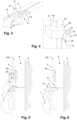
- Figure 1 diagrammatically show a front view of a wall cladding system 100 according to the invention, which is arranged on an exterior wall of a building.
- a door 1 and three windows 2 are present in the exterior wall.
- the wall cladding system 100 covers the entire area of the exterior wall outside of the door 1 and the windows 2, while at a position directly above each of the door 1 and the windows 2, a heat actuable device 3 according to the invention is present in the wall cladding system 100.
- the wall cladding system 100 comprises a number of stationary wall panel devices 4.
- Figures 2 , 3 and 4 illustrate a number of interesting aspects and options of the heat actuable device 3 according to the invention.
- the heat actuable device 3 is designed to have the normal appearance of a wall panel device of the wall cladding system 100 under normal circumstances, and to change to another state in a case of fire, in such a way that a fire retarding effect is obtained.
- the general set-up of the heat actuable device 3 is that the heat actuable device 3 comprises two basic arrangements, namely a wall panel arrangement 10 and a coupling arrangement 20.
- the wall panel arrangement 10 comprises a wall panel 11 such as a fiber cement panel. Further, as illustrated in figures 3 and 4 , it is possible that the wall panel arrangement 10 comprises a fireproof sheet such as a metal sheet 12, wherein the metal sheet 12 is located at a back side of the wall panel 11, i.e. at a side of the wall panel 11 facing the wall 5 of the building, the wall 5 constituting the background support of the heat actuable device 3.
- a fireproof sheet such as a metal sheet 12
- the metal sheet 12 is located at a back side of the wall panel 11, i.e. at a side of the wall panel 11 facing the wall 5 of the building, the wall 5 constituting the background support of the heat actuable device 3.
- the coupling arrangement 20 comprising a hinging arrangement 21 configured to allow the wall panel arrangement 10 to hinge about a hinge axis A.
- the hinging arrangement 21 comprises a hinging element 22 including two arms 23, 24 which are rotatable relative to each other about the hinge axis A.
- Another element of the coupling element 20 is an elongated coupling element 25.
- One arm 23 of the hinging element 22 is connected to a free end of the coupling element 25 and another arm 24 of the hinging element 22 is connected to the wall panel arrangement 10, as can best be seen in figure 2.
- Figure 2 also serves to illustrate that in the present example, the hinging arrangement 21 is attached to the wall panel arrangement 10 at an area of the wall panel arrangement 10 which is adjacent to a bottom edge 13 of the wall panel arrangement 10.
- the elongated coupling element 25 has a function in defining a distance between the back side of the wall panel arrangement 10 and the wall 5, so that a space 6 is present between the wall panel arrangement 10 and the wall 5, which space 6 is suitable to enable ventilation behind the wall panel arrangement 10.
- the coupling arrangement 20 comprises at least two combinations of a hinging element 22 and a coupling element 25, and if those at least two combinations are located at a distance from each other as seen in a width direction of the wall panel arrangement 10, i.e. a horizontal direction in the present example.
- the coupling arrangement 20 further comprises a holding arrangement 26 which has a function in holding the wall panel arrangement 10 in a normal cladding position relative to the wall 5, which in the present example is a position in which the wall panel arrangement 10 is substantially parallel to the wall 5, i.e. a position in which the wall panel arrangement 10 has a substantially vertical orientation.
- the holding arrangement 26 can come in many forms, including the form as shown, which is a form in which the holding arrangement 26 comprises a block-like element 27 made of a type of material that melts when subjected to high temperatures.
- the block-like element 27 is designed so as to engage on a substructure batten 5a arranged on the wall 5 on the one hand, and to engage on the wall panel arrangement 10 on the other hand.
- the block-like element 27 is provided with a tongue 28, and a top edge 14 of the wall panel arrangement 10 is provided with a groove 15 in which the tongue 28 fits.
- FIGS 5 and 6 provide an illustration of what happens with the heat actuable device 3 in the event of a fire.
- the heat actuable device 3 comes under the influence of flames 7 and the temperatures rise rapidly, the block-like element 27 melts, as a result of which the coupling of the wall panel arrangement 10 to the wall 5 at the position of the top edge 14 of the wall panel arrangement 10 is lost at a certain point.
- the wall panel arrangement 10 will then be in an unstable condition in which the wall panel arrangement 10 is inclined to hinge about the hinge axis A of the hinging element 22 and will actually do so under the influence of gravity and air flow.
- the wall panel arrangement 10 tilts from the substantially vertical orientation associated with the normal cladding position as shown in figure 5 to a substantially horizontal orientation as shown in figure 6 .
- a number of fire retarding effects are obtained, including an effect of hindering an upward movement of the flames 7 at the outside, an effect of hindering a chimney effect in the ventilation space 6, and an effect of enabling escape of smoke and heat from the ventilation space 6.
- a feasible alternative to the use of a meltable element 27 involves the use of an element such as double-sided adhesive tape at the position of which adhesion is lost under the influence of high temperatures.
- the coupling arrangement 20 comprises an arrangement 21 that is of a hinging character.
- a coupling arrangement 20 which is of the type comprising an arrangement that can be made to significantly extend under the influence of high temperatures associated with a fire is also feasible, in which case the distance between the wall panel arrangement 10 and the wall 5 is increased in the event of a fire so that an interruption of the wall cladding system 100 is realized.
- the arrangement that can be made to extend may be actually realized on the basis of a bimetallic element that assumes a significantly different shape under the influence of high temperatures.
- the coupling arrangement 20 comprises an arrangement that is of a hinging character, it is not essential that the wall panel arrangement 10 is enabled to hinge over an angle of about 90°. Other angles between the normal cladding position and the heat actuated position of the wall panel arrangement 10 are possible in the context of the invention.
- an advantageous option in respect of the wall panel arrangement 10 is an option according to which all of the panels and/or sheets included in the wall panel arrangement 10 are of fireproof quality.
- a heat actuable device 3 configured to be applied in a wall cladding system 100
- device 3 comprises a wall panel arrangement 10 and a coupling arrangement 20, wherein the coupling arrangement 20 is configured to allow a normal cladding position of the wall panel arrangement 10 relative to a background support 5, 5a and at least one other position, and also to keep the wall panel arrangement 10 fixed in the normal cladding position under normal circumstances and to release the wall panel arrangement 10 to move to another possible position under the influence of high temperatures associated with a fire as a way of hindering fire spreading.
Landscapes
- Engineering & Computer Science (AREA)
- Architecture (AREA)
- Civil Engineering (AREA)
- Structural Engineering (AREA)
- Building Environments (AREA)
Priority Applications (3)
| Application Number | Priority Date | Filing Date | Title |
|---|---|---|---|
| EP23152677.3A EP4403720A1 (de) | 2023-01-20 | 2023-01-20 | Wärmeaktivierbare vorrichtung zur verwendung in einem wandverkleidungssystem |
| EP24701224.8A EP4652335A1 (de) | 2023-01-20 | 2024-01-22 | Wandverkleidungssystem mit einem wärmeaktivierbaren mechanismus zur verhinderung der ausbreitung von feuer |
| PCT/EP2024/051405 WO2024153821A1 (en) | 2023-01-20 | 2024-01-22 | Wall cladding system comprising a heat-actuable mechanism for hindering spread of fire |
Applications Claiming Priority (1)
| Application Number | Priority Date | Filing Date | Title |
|---|---|---|---|
| EP23152677.3A EP4403720A1 (de) | 2023-01-20 | 2023-01-20 | Wärmeaktivierbare vorrichtung zur verwendung in einem wandverkleidungssystem |
Publications (1)
| Publication Number | Publication Date |
|---|---|
| EP4403720A1 true EP4403720A1 (de) | 2024-07-24 |
Family
ID=85018037
Family Applications (2)
| Application Number | Title | Priority Date | Filing Date |
|---|---|---|---|
| EP23152677.3A Pending EP4403720A1 (de) | 2023-01-20 | 2023-01-20 | Wärmeaktivierbare vorrichtung zur verwendung in einem wandverkleidungssystem |
| EP24701224.8A Pending EP4652335A1 (de) | 2023-01-20 | 2024-01-22 | Wandverkleidungssystem mit einem wärmeaktivierbaren mechanismus zur verhinderung der ausbreitung von feuer |
Family Applications After (1)
| Application Number | Title | Priority Date | Filing Date |
|---|---|---|---|
| EP24701224.8A Pending EP4652335A1 (de) | 2023-01-20 | 2024-01-22 | Wandverkleidungssystem mit einem wärmeaktivierbaren mechanismus zur verhinderung der ausbreitung von feuer |
Country Status (2)
| Country | Link |
|---|---|
| EP (2) | EP4403720A1 (de) |
| WO (1) | WO2024153821A1 (de) |
Citations (3)
| Publication number | Priority date | Publication date | Assignee | Title |
|---|---|---|---|---|
| US3968841A (en) * | 1975-06-04 | 1976-07-13 | Canadian Patents And Development Limited | Flame deflecting device for mounting on a building exterior |
| EP1092837A2 (de) * | 1999-10-11 | 2001-04-18 | Liederer + Partner GmbH | Brandschutzvorrichtung für Tunnels |
| CN110173081A (zh) * | 2019-06-27 | 2019-08-27 | 中民筑友房屋科技集团有限公司 | 一种装配式干法精装体系 |
Family Cites Families (1)
| Publication number | Priority date | Publication date | Assignee | Title |
|---|---|---|---|---|
| AU2020268212B2 (en) * | 2019-05-08 | 2025-08-14 | Benjamin Hughes-Brown | A fire barrier assembly and method of use thereof |
-
2023
- 2023-01-20 EP EP23152677.3A patent/EP4403720A1/de active Pending
-
2024
- 2024-01-22 EP EP24701224.8A patent/EP4652335A1/de active Pending
- 2024-01-22 WO PCT/EP2024/051405 patent/WO2024153821A1/en not_active Ceased
Patent Citations (3)
| Publication number | Priority date | Publication date | Assignee | Title |
|---|---|---|---|---|
| US3968841A (en) * | 1975-06-04 | 1976-07-13 | Canadian Patents And Development Limited | Flame deflecting device for mounting on a building exterior |
| EP1092837A2 (de) * | 1999-10-11 | 2001-04-18 | Liederer + Partner GmbH | Brandschutzvorrichtung für Tunnels |
| CN110173081A (zh) * | 2019-06-27 | 2019-08-27 | 中民筑友房屋科技集团有限公司 | 一种装配式干法精装体系 |
Also Published As
| Publication number | Publication date |
|---|---|
| EP4652335A1 (de) | 2025-11-26 |
| WO2024153821A1 (en) | 2024-07-25 |
Similar Documents
| Publication | Publication Date | Title |
|---|---|---|
| JP5504143B2 (ja) | サッシ | |
| US20070204540A1 (en) | Means and method for fireproof sealing between the peripheral edge of individual floors of a building and the exterior wall structure thereof | |
| JP5566325B2 (ja) | サッシ | |
| JP6240546B2 (ja) | サッシ窓用の換気装置及びサッシ窓 | |
| JP5463113B2 (ja) | 軒先構造 | |
| JP5595889B2 (ja) | サッシ | |
| KR101995447B1 (ko) | 알루미늄 박판층과 유리섬유 망층을 이용하여 무기질 평탄층이 고도의 일체성을 가지는 건축용 조립식 복합 외장구조체 | |
| EP1025320B1 (de) | Feuerbeständige dachkonstruktion | |
| US3968841A (en) | Flame deflecting device for mounting on a building exterior | |
| CN102947532B (zh) | 具有一个或两个门扉的防火门 | |
| GB2296263A (en) | Firebreak for building overcladding | |
| NO348154B1 (en) | A ventilated façade cladding system and a method of constructing a cavity fire compartment | |
| JP2012127182A (ja) | サッシ | |
| KR20190109869A (ko) | 화재 확산 방지를 위한 방화 구조 | |
| WO2019096882A1 (en) | Fire proof exterior cladding panel | |
| EP4347971B1 (de) | Ein system für hinterlüftete fassadenverkleidungen | |
| WO2024153821A1 (en) | Wall cladding system comprising a heat-actuable mechanism for hindering spread of fire | |
| JP5566326B2 (ja) | サッシ | |
| CN209413771U (zh) | 一种钢质隔热防火门 | |
| JP3146130B2 (ja) | 軒先通気防火構造 | |
| WO2025157816A1 (en) | Wall cladding system comprising wall panel arrangements and a fire-hindering body | |
| KR100695686B1 (ko) | 건축물 외벽에 설치되는 방화판 | |
| JP5736222B2 (ja) | サッシ | |
| EP3739140B1 (de) | Brandschutzwandstruktur-anordnung zum trennen benachbarter räume | |
| JP3456752B2 (ja) | 小屋裏または軒裏の防火界壁 |
Legal Events
| Date | Code | Title | Description |
|---|---|---|---|
| PUAI | Public reference made under article 153(3) epc to a published international application that has entered the european phase |
Free format text: ORIGINAL CODE: 0009012 |
|
| STAA | Information on the status of an ep patent application or granted ep patent |
Free format text: STATUS: THE APPLICATION HAS BEEN PUBLISHED |
|
| AK | Designated contracting states |
Kind code of ref document: A1 Designated state(s): AL AT BE BG CH CY CZ DE DK EE ES FI FR GB GR HR HU IE IS IT LI LT LU LV MC ME MK MT NL NO PL PT RO RS SE SI SK SM TR |
|
| STAA | Information on the status of an ep patent application or granted ep patent |
Free format text: STATUS: REQUEST FOR EXAMINATION WAS MADE |
|
| 17P | Request for examination filed |
Effective date: 20250124 |